Study on Flow Field and Rotor Safety Characteristics of MSPs Based on Flow Thermo-Coupling


1
Hubei Key Laboratory of Hydroelectric Machinery Design & Maintenance, China Three Gorges University, Yichang 443002, China
2
National Research Center of Pumps, Jiangsu University, Zhenjiang 212013, China
*
Authors to whom correspondence should be addressed.
Processes 2019, 7(10), 711; https://doi.org/10.3390/pr7100711
Submission received: 17 September 2019
/
Revised: 26 September 2019
/
Accepted: 29 September 2019
/
Published: 8 October 2019
(This article belongs to the Section Chemical Processes and Systems)
Abstract
:In order to obtain the structural intensity under the operation conditions of MSP (molten salt pump), the rotor component of MSP is taken as the research object. In this paper, the influence of material properties change on the structural performance of MSP at different temperatures is analyzed. The stress distribution and strain distribution of MSP rotor components under different loads are investigated, and the intensity calculation of MSP rotor system is carried out to explore whether it meets the intensity requirements under high temperature operation, which lays a foundation for the high temperature test of MSP. The results show that the maximum deformation position of the blade working face appears at the outer edge of the impeller. When the fluid-structure coupling is applied, the blade strain law and the strain law during thermo-coupling are similar. The effect of the temperature field on the degree of blade deformation is not significant, provided that other factors remain the same. The position where the impeller equivalent stress is the largest is mainly concentrated in the area where the blade is in contact with the front and rear cover plates at the outlet of the impeller. Different degrees of stress concentration occur in the area where the blade is in contact with the impeller hub. The distribution law of the equivalent stress on the surface of the impeller cover plate is that the equivalent stress value changes periodically along the circumferential direction of the impeller, and the number of change cycles is equal to the number of impeller blades. This study can provide a reference for the structural design of MSPs.
1. Introduction
MSP (molten salt pump) is a key equipment in many chemical processes. It is used for the transportation of high-temperature nitrate, fluoride salt, and ion-exchange membrane caustic soda. It is also widely used in industrial aluminum production, salt production, alkali production, and urea. With the continuous advancement of technology, high-temperature molten salt has also been promoted and applied in new photovoltaic thermal storage power stations and nuclear energy fields [1,2,3]. Because the temperature of the medium used for industrial MSP is usually between 400~460 °C [4], its operation stability and reliability are high, so it is of great significance to analyze the structural intensity of MSP.
In the field of fluid mechanics, the fluid-structure coupling under normal temperature conditions was initially studied to analyze the influence of fluid-structure coupling on the flow field distribution and solid structure in fluid machinery. Shouqi Y. et al. [5] took the spiral centrifugal pump as the research object, and compared the flow law inside the pump when there is fluid-structure coupling and no fluid-structure coupling. It was found that the fluid-structure coupling enhances the pressure fluctuation at the pump inlet and increases the flow asymmetry in the impeller. Qilei W et al. [6] used the fluid-structure coupling method to analyze the multi-stage centrifugal pump, and found that the stress, strain, and deformation on the impeller showed an increasing trend with time. However, with the deepening of research, more and more scholars have begun to notice the influence of temperature field on the fluid and solid domains, and use thermo-coupling and fluid-structure coupling to study the structural intensity of fluid mechanical structures and their components. Pita CM [7], Pironkov P [8], and Takizawa K [9] wrote the corresponding procedures in their papers to study the deformation and stress distribution of two-dimensional circular tubes and flat plates under high temperature fluids by means of flow thermo-coupling. Senn SM et al. [10] predicted the interaction of fluid and structure in a turbocharger. Ricet T [11] used numerical simulation of the blade flutter problem under the high flow condition of the extremely long rotating blade of steam turbine, and analyzed the cause of unstable aero dynamics. Fanyu K et al. [12,13] used thermo-mechanical coupling and flow thermo-coupling to analyze the stress and strain of the pump body and the impeller, and obtained the deformation and stress distribution of the solid structure, and checked the structural intensity of the pump. Liang D et al. [14] used unidirectional fluid-structure coupling to analyze the structural stress distribution characteristics of the pump under normal temperature and high temperature and high pressure conditions. Based on the constant flow field, Fulei Y et al. [15] analyzed the deformation and stress distribution of rotor blades by flow thermo-coupling and checked the blade strength.
At present, because of the generalized variational principle of the fluid-structure coupling system and the theory of the finite element format, the direct coupling method under the same coupled coordinate system cannot deal with the fluid-structure coupling problems in complex practical engineering.
In summary, because high-temperature molten salt is denser than ordinary clean water, internal flow is more complicated than ordinary clean water pump. Moreover, it operates in a high temperature environment, and the rotor component is greatly deformed by the pressure inside the pump and the high temperature at a high temperature. Therefore, the influence of temperature and flow field needs to be considered in the structural performance analysis of the MSP. In the field of MSP, the research on the internal flow and hydraulic performance of MSP is rarely involved, and the stress and strain analysis of the rotor component of MSP under high temperature conditions is rarely involved. However, with the practical engineering problems, the research on the internal heat-solid coupling in the field of MSP has become more and more urgent.
This paper mainly analyzes the influence of material properties change on the structural performance of MSP at different temperatures, and investigates the stress distribution and strain distribution of MSP rotor components under different loads. The intensity calculation of MSP rotor system is carried out to find out whether it meets the intensity requirements under high temperature operation, which lays a foundation for the high temperature test of MSP.
In the introduction, the paper points out the lack of research on the stress and strain analysis of MSP rotor components under high temperature conditions. The flow-thermal coupling solution strategy is used in the research method. The effects of material properties on the structural properties of MSP under high temperature conditions are investigated. The strain distribution and stress distribution of MSP rotating system under different loads are studied.
2. Research Methods
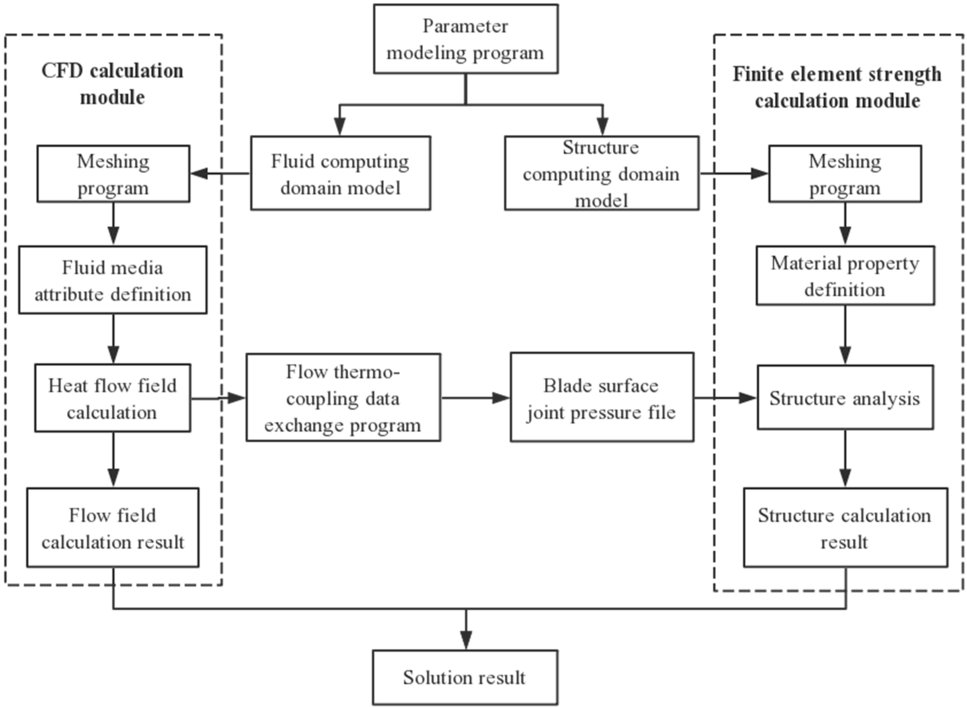
Based on the commercial software ANSYS Workbench, the MSP rotor components are taken as the research object. The hydrodynamic load, centrifugal force load, and the temperature load of the MSP are comprehensively considered to establish the dynamic model under the action of heat, flow, and solid coupling. Thermal-structure coupling, fluid-structure coupling, and flow thermo-coupling were carried out under three temperature conditions. At the same time, the iterative coupling solution strategy is selected, and the fluid domain and the solid domain are separately solved in their respective coordinate systems. Through the coupling interface for bidirectional data transmission, the solution of the high-temperature pump end-flow excitation fluid-structure coupling system is realized. The effects of material properties change on the structural performance of MSP at different temperatures were studied. The stress distribution and strain distribution of MSP rotor components under different loads were investigated. The flow heat-solid coupling calculation method flow chart used in this paper is shown in Figure 1.
As shown in Figure 1, the fluid computing domain model and the structure computing domain model of the pump are established in the parameter modeling program and input into the CFD calculation module and the finite element structure calculation module. The fluid calculation model calculates the heat flow field after meshing. In the finite element structure calculation module, after the structure is meshed, it is necessary to define the material properties of the material, and load the calculated blade surface pressure file in the CFD onto the structure for coupling calculation. When the coupling accuracy reaches a certain requirement, the CFD calculation module and the finite element strength calculation module respectively output the flow field calculation structure file and the finite element strength calculation result. Finally, a comprehensive analysis of the above two documents is presented.
2.1. Calculation Model
The design parameters of the molten salt pump (MSP) model used in this paper are shown in Table 1 below.
The model impeller is a closed impeller, the pump shaft adopts a cantilever structure, and there are two bearing installation positions on one side of the impeller. The loose bearing is mounted in bearings near the impeller, and fixed bearings is mounted on bearings that are remote from the impeller. Using space-guided blades, the structure is a vertical long-axis pump, as shown in Figure 2.
In order to accurately describe the true flow of the fluid, the entire flow region is used as a numerical simulation region. The inlet and outlet of the pump is exteded to reduce the influence of flow instability on the simulation results and improve the accuracy of numerical simulation. The entire calculation area includes the section, the impeller, the vane diffuser, and the outlet section. The combined water body of the entire flow-through component is shown in Figure 3.
2.2. Meshing and Grid Correlation Analysis
The fluid computing domain is meshed by using ICEM CFD. In order to ensure the accuracy and accuracy of the calculation results, the impeller and the space guide vane are unstructured mesh, the structure mesh is divided into the inlet and outlet sections. Partially encrypt some water bodies (such as the interface) to ensure that all mesh quality is above 0.3.
In order to accurately describe the true flow of the fluid, the entire flow region is used as a numerical simulation region. Under the premise of reducing the influence of flow instability on the simulation results, the accuracy of numerical simulation is improved, and the inlet and outlet of the pump are appropriately extended. That is, an extension of four times the diameter of the pipe is added to the impeller inlet and the vane diffuser outlet respectively. The entire calculation area includes the inlet section, the impeller, the vane diffuser, and the outlet section. Figure 4 is a meshing diagram of the assembly.
The grid is divided into six sets of different grids, and the grid independence check is performed with the efficiency deviation prediction of different schemes within 1%. Figure 5 shows the relationship between the hydraulic efficiency of the MSP and the number of grids.
It can be seen from Figure 5 that when the number of meshes exceeds 1.65 million, the hydraulic efficiency of the calculation model remains basically unchanged. It can be considered that the number of grids at this time has little effect on the accuracy and the accuracy of the simulation calculation. Therefore, based on the comprehensive consideration of computational economics, the final grid scheme is: the inlet section, the impeller, the space-guided blade, and the outlet section have grid numbers of 61,259, 1,253,692, 256,931, and 82,694, respectively.
3. Numerical Calculation
3.1. Fluid Domain Calculation Settings
The three-dimensional unsteady Reynolds time-averaged Navier–Stokes equation was solved using the commercial software ANSYS CFX 14.5. The total pressure and flow direction under the static coordinate system of the inlet are important boundary conditions, which are estimated from the relevant data measured by the test. The outlet boundary condition is set to mass flow, measured and calculated by the flow meter.
Because the molten salt medium is a high viscosity fluid medium under high temperature conditions, and the SST k-ω turbulence model is more suitable for high viscosity fluid calculation. Therefore, the SST k-ω turbulence model selected in the steady calculation is used. The SIMPLE algorithm is used to couple pressure and velocity. The interface is set by the frozen rotor and the steady state calculation is used as the initial condition for the unsteady calculation. In the unsteady calculation, the turbulence model uses the SST (shear stress transfer) model with an initial turbulence intensity factor of 5%.
The choice of the discrete format of the convection term has an impact on the reliability, accuracy, and convergence of the calculation, and is a mutually constrained relationship. Usually, the blend factor can be chosen to be 0.75. However, according to the calculation model of this paper, the calculation stability can be obtained with the parameter of 1.0, and the spatial dispersion of precision is the second-order precision. The time is discretely selected in the second-order backward Euler format.
The coupling surface between the rotating area and the stationary area adopts a “transient rotor-static model.” The main function is to capture the interaction between the transient rotor and the stator during relative motion. The wall is set to a sliding wall condition. The reference pressure of all calculation areas is set to 0 Pa, and the pressure value obtained by CFX is the absolute pressure value. Since the boundary conditions of the import and export of this calculation are completely set according to the test value, the working condition at the time of calculation is consistent with the test condition.
The calculation of CFX software uses a unique implicit Euler time-discrete method, and the calculation result is numerically stable, and there is no particular limitation on the selection of the time step. The time step of the transient calculation is determined based on the angle of rotation of each step of the impeller. The impeller rotates one step at a time, that is, one impeller rotation period includes 120 time steps. Taking into account the frequency domain range of dynamic and static interference results, the calculation accuracy can fully satisfy the capture of unstable components of dynamic and static interference. Therefore, for a nominal speed of n = 1490 rpm, the time step is 3.4 × 10⁻⁴ s. In addition, the iterative convergence criterion in each time step is that the maximum residual is 10−4 in each time step and the maximum iteration step is set to 10.
Selecting the material at the corresponding temperature and the properties of the medium for simulations at different temperatures, the calculation conditions are different operating conditions at three temperature states of 300 °C, 400 °C, and 500 °C operating temperature: 0.4 Qd, 1.0 Qd, and 1.3 Qd.
3.2. Structure Domain Calculation Settings
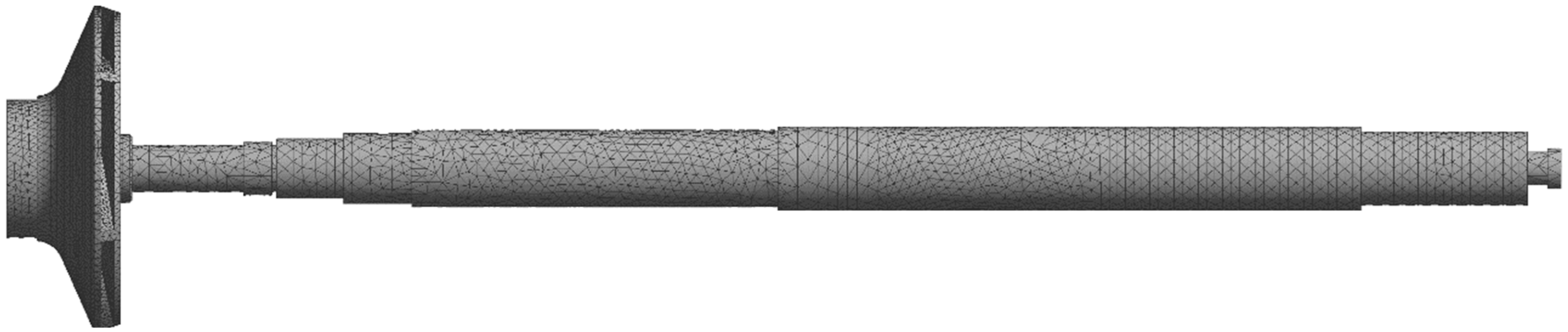
In order to obtain a finite element mesh with good orthogonality, the solid model uses a Hex hexahedral mesh-based finite element mesh. The tool for generating the mesh is ANSYS Structure Mesher, and the mesh is automatically encrypted at some key positions. Figure 6 shows the finite element mesh of the rotor system model. The grid-independent verification verifies the number of the solid-domain grids 122,252.
Because the working medium is high-temperature molten salt, in order to make the rotating parts have better mechanical properties and high temperature resistance, the materials of the impeller and the pump shaft are all made of 316 L duplex stainless steel, which is the basic condition for structural finite element analysis.
The physical properties of water and molten salt at different temperatures are shown in Table 2.
The physical properties of 316 L at different temperatures are shown in Table 3.
In order to ensure the accuracy of the calculation results, cylindrical support is applied to the pump shaft bearing (A, B in Figure 7), and the gravity load is applied as a whole (E in Figure 7). In addition, in order to load the fluid force onto the structure, the shaft end is fixedly constrained. Since the rotor structure is not only subjected to the reaction force of the fluid to it, but also subjected to the centrifugal force of rotation, it is necessary to apply a centrifugal force load (1450 r/min) to the rotating member (C in Figure 7). A friction-free constraint (D in Figure 7) is added to the shoulder of the bearing inner ring to limit the displacement in the direction of gravity. The application of the load is shown in Figure 7.
In order to accurately transfer the load, all the coupling faces need to be accurately matched in the setting process. In this paper, five sets of coupling faces are set up, including the impeller blade surface, the inner and outer surfaces of the front cover, and the inner and outer surfaces of the rear cover.
4. Numerical Calculation Results and Analysis
In order to analyze the flow law of the MSP and determine the stress distribution, two coordinate systems are established. One is a stationary coordinate system (x, y) for determining the position of the blade, and the other is a rotating coordinate system (ξ, ψ) for determining the position of the circumference. The angle between the ψ axis of the rotating coordinate system and the y axis of the stationary coordinate system is the angle of rotation of the impeller, and the counterclockwise direction is positive. The stationary coordinate system is used to solve the volute area in CFX. The rotating coordinate system is used to solve the impeller flow field and impeller structure in ANSYS. The purpose of this calculation is to ensure that the impeller flow field grid can communicate with the finite element mesh in real time.
4.1. Comparison of Test Results
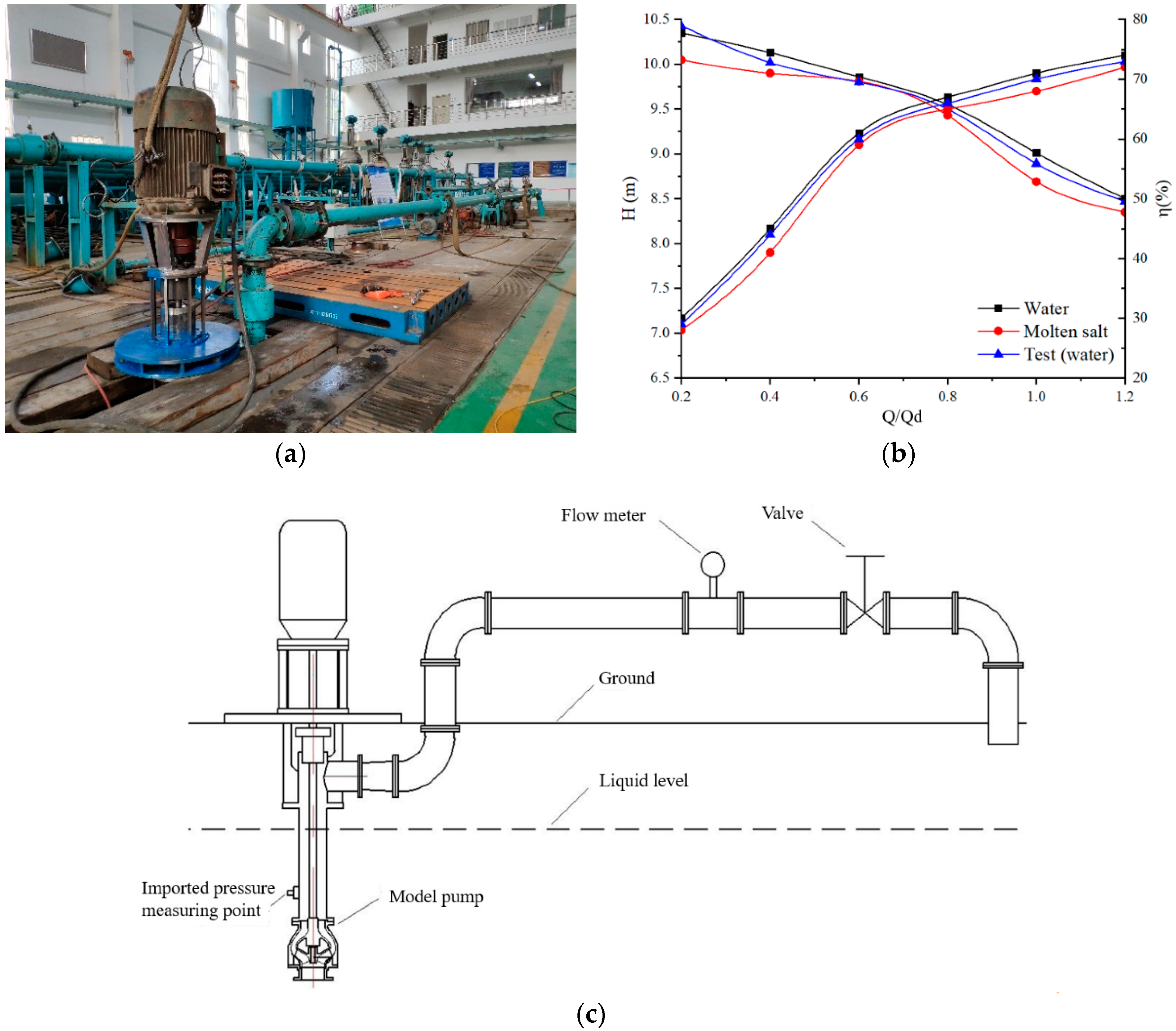
In order to verify the reliability of the numerical calculation, the external performance test of the model pump with normal temperature water is carried out. Figure 8a is the picture scene of experiment, and Figure 8b is the comparison of simulation results and experiment results, and Figure 8c is the test schematic. It can be seen from the Figure 8 that the trend of the numerical simulation results and the test results are basically the same. In the 0.2 Qd ~1.2 Qd flow range, the relative deviations of the head and efficiency are within 5% and 3%, respectively. At 1.0 Qd, the relative errors of the efficiency and head values are 2.85% and 3.45%, respectively. This shows that the numerical simulation method of this paper has good accuracy and calculation accuracy, and can be used for numerical simulation of internal flow of MSP.
It can be seen from Figure 8b that when the pump calculates the water and the molten salt medium separately, the pump is gradually operated from a small flow condition (0.2 Qd) to a large flow condition (1.2 Qd). The corresponding heads accounted for 22.99% and 21.06% of the design head, respectively. It can be seen that the external characteristic curve of the pump is relatively stable, and there is no obvious hump or other situation.
In addition, the efficiency when using water as a medium is slightly higher than that when using molten salt as a medium, and as the pump gradually changes from a small flow condition to a large flow condition, the efficiency difference between the two gradually decreases. The head with water as the medium is always higher than the head with molten salt as the medium. At the design working point, the difference between the two heads is the smallest. From the small flow condition point to the design flow point, the head difference gradually decreases. From the design point to the large flow condition point, the head difference gradually increases. The reason for this phenomenon is that on the one hand, the flow pre-spin and the secondary flow of the two media are different under small flow conditions. On the other hand, the loss during transport is different because of the different viscosity of the medium.
4.2. Internal Flow Analysis
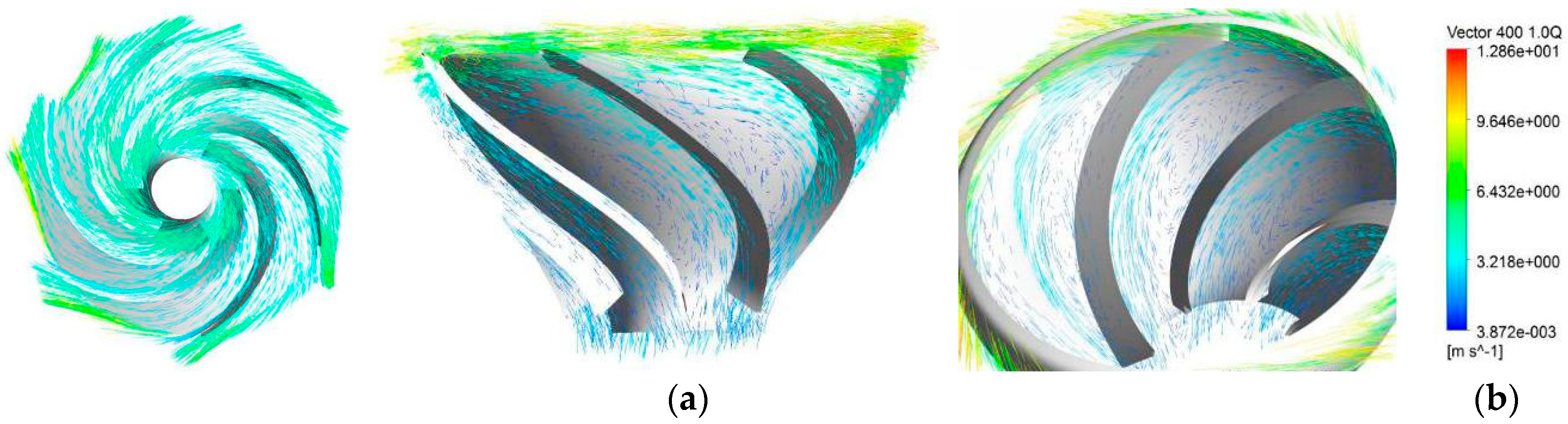
Figure 9 is a velocity vector diagram of the design under the condition that the medium is 400 °C. It can be seen from Figure 9a that the internal velocity distribution of the impeller is symmetrically distributed along the blade. Because of the narrow flow path of the impeller, the position of the blade inlet near the front cover plate is relatively high, indicating that the blade impact is large, which will cause impact loss and reduce efficiency; however, the velocity distribution in the entire impeller flow passage is relatively uniform.
It can be seen from Figure 9b that the fluid flows uniformly along the space guide vanes, but because of the long space of the space guide vanes, there is a slight vortex and reflow phenomenon in the flow passage, and the speed trend is basically consistent with the trend of the streamline diagram. The vanes can convert high fluid kinetic energy into lower pressure energy, which reduces the energy lost by high-speed rotation to a certain extent. Furthermore, it can be seen from Figure 9b that the area behind the middle section of the back side of the vane has a slight partial vortex because of the influence of the vane outlet fluid and the back side flow. The occurrence of these vortices will cause the fluid flow state to be disordered to a certain extent. This is described in the literature [16,17]: a large range of vortices appear in the internal flow of the vane diffuser and are concentrated in the back of the vane diffuser. When the pump is operated in non-design conditions, the distribution of the internal flow field will be greatly deteriorated and the performance of the pump will be affected.
When the operating condition of the pump changes, the flow of the fluid medium into the water outlet pipe through the rectification of the vane is complicated. Therefore, the pressure fluctuation wave of the monitoring point in the outlet pipe is different under different operating flow conditions. In order to more clearly observe the pressure fluctuations of the monitoring points in the outlet pipe during different operating flow conditions, the pressure pulsation time domain diagrams of the four operating conditions are respectively made, as shown in Figure 10.
It can be seen from Figure 10 that when the pump operation condition is gradually increased from the small flow operating point (0.4 Qd) to the large flow operating point (1.2 Qd), the pressure wave amplitude shows a trend of increasing first and then decreasing (design the flow point as the boundary line). As the operating conditions increase, the pressure pulsation time domain diagram gradually changes. At 0.4 Qd, six peaks and six troughs appear in the regularity of the pressure wave, and the phenomenon of secondary peaks and secondary troughs near each peak and trough is not obvious.
When the running flow increases to 0.8 Qd, the secondary peak and the second wave valley value increase gradually with the increase of time in the 0.5 T~1 T time period, which is approximately equal to the peak value. When the pump is running at the design flow operating point, as shown in Figure 10c, the pressure value always fluctuates regularly around an equilibrium value throughout the operating cycle, but there are no obvious peaks and troughs. When the pump is running at a high flow operating point (1.2 Qd), the pressure pulsation wave still fluctuates near the equilibrium position, and the values of the secondary peak and the secondary trough have fully developed to equal the peak and trough values. Therefore, 12 peaks and 12 troughs can be seen throughout the cycle.
4.3. Deformation Analysis
Figure 11 and Figure 12 show the blade working face and back deformation cloud diagram when the impeller is fluid-structure coupling. It can be seen from Figure 11 and Figure 12 that as the operating point increases, the maximum value of the blade deformation gradually increases, but the minimum value of the deformation is defined by the design flow point, which tends to decrease first and then increase. The blade working surface and the back deformation law are similar in each flow condition point. Taking the design flow condition point as an example, the area where the blade working surface is deformed is located in the middle section of the blade and extends to the outlet of the impeller. The area where the back surface of the blade is obviously deformed extends from the outlet at the back of the blade to about 1/3 from the outlet of the blade. The degree of deformation increases with the increase of the radius. The closer to the outlet, the more severe the deformation. In general, the area of deformation of the working surface is much larger than that of the back side.
Because of the large pressure difference between the suction side and the pressure surface of the impeller, the deformation of the blade is caused. By analyzing the pressure cloud map of the blade surface, the pressure of the suction surface of the blade shows a significant increasing trend from the inlet edge to the outlet edge, especially in the vicinity of the inlet side of the suction side of the blade. The pressure change on the pressure surface is not so obvious, so the maximum deformation of the structure generally occurs at the impeller inlet rim.
Table 4 below shows the relevant data of impeller working surface and back surface thermal deformation under different working conditions of impeller thermo-coupling.
Figure 13 below shows the deformation cloud diagram under different flow conditions when the model pump operating temperature is 500 °C. The left side is the blade working face and the right side is the blade back side.
In Table 4, it can be found that the degree of thermal deformation of the blade changes with the temperature of the fluid medium, and the thermal deformation amount of the back surface of the impeller blade is similar to that of the working surface. Figure 13 below shows the deformation cloud diagram under different flow conditions when the model pump operating temperature is 500 °C. The upper side is the blade working face and the lower side is the blade back side.
It can be seen from Figure 13 that when the temperature field is the same, during the process of running flow rate from small flow (0.4 Qd) to large flow (1.3 Qd), the deformation position and deformation law of the blade are almost the same as the thermo-coupling law. The maximum deformation of the blade occurs near the impeller inlet and the front cover. The minimum value of blade deformation is at the position where the blade is in contact with the rear cover. On the same circumference, the deformation near the front cover region is more pronounced than the shape near the rear cover region, and the degree of deformation of the blade as a whole gradually decreases from the hub to the rim. Under the same working conditions, as the temperature increases, the maximum deformation value observed on the impeller increases first and then decreases.
Under the action of flow thermo-coupling, the cause of the impeller deformation degree increases first and then decreases with increasing temperature as follows.
(1) The physical properties of fluid media do not have a stable law with temperature changes. At the same time, the irregularity of m deformation degree may be related to the internal flow result caused by the different physical properties of the fluid medium.
(2) The strength of the impeller material is very different from that at room temperature at high temperatures, and the deformation mechanism of the material itself increases under high temperature conditions.
(3) The corrosive effect of the fluid medium on the material increases with the increase of temperature, which also affects the mechanical properties of the material itself.
From the above analysis of the deformation of the blade, it is known that the influence of the temperature field on the degree of deformation of the blade is not significant under the condition that other factors are ensured.
4.4. Intensity Analysis
The medium transported by MSP is high temperature nitrate. The thermal load is generally considered from two aspects: on the one hand, the high temperature causes the heated component to fail; on the other hand, the excessive temperature gradient causes the heat-receiving component to generate a large thermal effect, thereby causing thermal fatigue or even damage. In this paper, the intensity of the impeller is obtained by analyzing the equivalent stress of the impeller at different operating temperatures.
The equivalent stress distribution obtained by fluid-structure coupling of the rotating parts of the model pump under different working conditions at 500 °C operating temperature is shown in Figure 14.
By comparison, it is found that the maximum equivalent stress appears in the impeller outlet under different working conditions (the position where the rear cover and the back of the blade meet). This is due to the large pressure at the outlet of the impeller, the small thickness at the outlet of the blade, and the stress concentration at the intersection of the blade and the cover. It can be seen from Figure 14 that as the operating flow point gradually increases, the maximum equivalent stress of the impeller gradually decreases. Compared with the maximum equivalent stress value of the designed flow operating point, the maximum equivalent stress value of the low flow condition (0.4 Qd) is increased by 5.06%, and the maximum equivalent stress value of the large flow condition (1.3 Qd) is increased by 6.24%.
The following is a correlation analysis of the stress of the blade during flow thermo-coupling at an operating temperature of 500 °C, as shown in Table 5.
It can be seen from Table 4 that the stress value of the blade working surface is higher than the stress value of the back surface of the blade, and the stress values of the impeller working surface and the back surface tend to decrease linearly under different working conditions.
Referring to Figure 14, it can be found that the maximum area of the impeller equivalent stress at 500 °C is mainly concentrated in the area where the blade and the front and rear cover are in contact at the impeller outlet, and reaches a maximum at 0.4 Qd, as shown in Figure 15.
It can be seen from Figure 15 that the maximum equivalent stress of the impeller is 45.024 MPa. When the intensity check is performed, the safety factor of 316 L is taken as nb = 2 at 500 °C, and the yield stress of 316 L stainless steel is σb = σs = 94.45 MPa. Therefore, at 500 °C, the numerical simulation, the calculated impeller safety factor is 2.137. Therefore, the impeller intensity meets the intensity requirement at 500 °C.
The above results show that the region with the largest equivalent stress of the impeller is mainly concentrated in the area where the blade is in contact with the front and rear cover plates at the outlet of the impeller. Mainly because of the discontinuity of the structure of the region and its sharp structural features, the stress cannot be released by elastic deformation, which tends to cause stress concentration at the near fulcrum of the blade. Through the above analysis, the distribution law of the equivalent stress on the surface of the impeller cover plate can be obtained, that is, the equivalent stress value changes periodically along the circumferential direction of the impeller, and the number of change cycles is equal to the number of impeller blades.
5. Discussion
In actual engineering, the safety of the impeller is deformed because of the high temperature of the fluid medium, and the sealing surface is deformed, which seriously affects the operational reliability of the pump. The most intuitive manifestation of the rotating system under load is that the structure is deformed. As the main component of the rotating system, the impeller blade is directly represented by the stress distribution under the load. This indicates that the stress distribution of the MSP rotating system under different loads is explored, and the strain distribution law is extremely important. At the same time, in order to ensure the operational reliability of the impeller, the strength needs to be checked.
Some scholars have fluid-solid coupling to the centrifugal pump, and found that the impeller deformation increases with the increase of the radius. In this paper, the hydraulic performance test of the model pump prototype is carried out, and the corresponding numerical simulation results are compared with the test results. At the same time, the model pump is subjected to unidirectional fluid-solid coupling numerical simulation calculation. When the interaction between fluid domain, solid domain, and temperature field is analyzed, the stress distribution and strain distribution of MSP rotating system under different loads are investigated. The results show that on the same circumference, the deformation near the front cover region is more obvious than the change near the rear cover region, and the degree of deformation of the blade as a whole gradually decreases from the hub to the rim. Under the same flow conditions, the maximum value of impeller blade deformation is not significantly different with the temperature of the fluid medium. The stress value of the blade working face is higher than the stress value of the back surface of the blade. The region with large stress value appears in the middle of the blade working face near the outlet, but the stress contact between the blade and the impeller hub occurs to different extents. The distribution law of the equivalent stress on the surface of the impeller cover plate is that the equivalent stress value changes periodically along the circumferential direction of the impeller, and the number of change cycles is equal to the number of impeller blades.
6. Summary
(1) When the water is used as the medium, the efficiency of the pump is slightly higher than that when the molten salt is used as the medium, and as the pump gradually changes from the small flow condition to the large flow condition, the efficiency difference between the two gradually decreases.
(2) When the flow field conditions are the same, the deformation degree of the blade under the action of fluid-solid heat and thermo-coupling is not much different, which is about 40 times of the shape variable calculated by the fluid-structure coupling. By analyzing the deformation of the blade, it is known that the influence of the temperature field on the degree of deformation of the blade is not significant under the condition that other factors are ensured.
(3) The maximum deformation of the blade occurs near the impeller inlet and the front cover. The minimum deformation of the blade is where the blade contacts the rear cover. On the same circumference, the deformation near the area of the front cover is more obvious than the change of the shape near the area of the rear cover. The degree of deformation of the blade is gradually reduced from the hub to the rim as a whole, and the area where the blade working surface is deformed is larger than the area where the back surface is deformed. In addition, under the same flow conditions, the maximum value of impeller blade deformation is not significantly different with the temperature of the fluid medium.
(4) The position of the impeller equivalent stress is mainly concentrated in the area where the blade and the front and rear cover are in contact at the outlet of the impeller. The distribution law of the equivalent stress on the surface of the impeller cover plate is that the equivalent stress value changes periodically along the circumferential direction of the impeller, and the number of change cycles is equal to the number of impeller blades.
Author Contributions
Y.C. the writing and revision of the paper; Y.C. and Y.L.: experiments and simulations; R.Z. and Z.G.: ideas and fund support of the paper; J.K.: experimental and simulated data processing.
Funding
National Key Research and Development Project (2018YFB0606105); “Supported by the Open Research Fund of Key Laboratory of ministry (provincial), (Sanxia University)” (2017KJX14); National Natural Science Foundation of China (51379091); A science and technology program funded by Natural Science Foundation of Jiangsu Province (BK20130516); National Youth Natural Science Foundation of China (51509112); Key R & D programs of Jiangsu Province of China (BE2015129 & BE2016160); Prospective joint research project of Jiangsu Province (BY2016072-02); The China Postdoctoral Science Foundation Funded Project (2019M651734); National Youth Natural Science Foundation of China (51906085).
Conflicts of Interest
The authors declare no conflict of interest.
Nomenclature
| Q | Volume flow rate, m3/h | p | Medium density, kg/m3 |
| Qd | Limited volume flow rate, m3/h | T | Temperature, °C |
| H | Head of the pump, m | E | Elastic modulus, GPa |
| Hd | Limited head of the pump, m | σs | Yield intensity, MPa |
| n | rotational speed, rpm/ | µ | Dynamic viscosity, Pa∙s |
| Z | Number of impellers | C | Specific heat capacity, J/kg/K |
| Z1 | Number of vane diffuser | K | Thermal conductivity, W/m/K |
| η | Effectiveness, % | σb | Tensile strength, MPa |
| Cp | Pressure coefficient | nb | Safety factor |
| t | Time, s |
References
- Xing, S. 10 MW Solar Thermal Power Tower System Dynamic Simulation Model. Master’s Thesis, North China Electric Power University, Beijing, China, 2014. [Google Scholar]
- Yuting, W.; Nan, R.; Chongfang, M.; Bin, L. Independent thermal storage power station with molten salt: Technology and evaluation. Energy Storage Sci. Technol. 2014, 3, 191–196. [Google Scholar]
- Chao, G. Theoretical and Experimental Research on Multifunctional Solar Photovoltaic Photothermal Collector. Ph.D. Thesis, University of Science and Technology of China, Hefei, China, 2015. [Google Scholar]
- Tao, Z.; Xiaohua, L.; Kang, Z.; Yi, J. Application Analysis of Temperature and Humidity Independent Control Air Conditioning System. Build. Sci. 2010, 26, 146–150. [Google Scholar]
- Yuan, S.; Xu, Y.; Zhang, J.; Pei, J.; Zhou, J. Numerical Analysis for Effect of Fluid-structure Interaction on Flow Field in Screw Centrifugal Pump. Trans. Chin. Soc. Agric. Mach. 2013, 44, 38–47. [Google Scholar]
- Qilei, W.; Guodong, C. Characteristic and Experimental of Fluid-structure Interaction of Multistage Pump Rotor. Fluid Mach. 2015, 7, 10–15. [Google Scholar]
- Pita, C.M.; Felicelli, S.D. Fluid-solid interaction problems with thermal convection using the immersed element-free Galerkin method. Int. J. Numer. Methods Fluids 2010, 62, 1–23. [Google Scholar] [CrossRef]
- Pironkov, P. Numerical Simulation of Thermal Fluid-Structure Interaction. Ph.D. Thesis, Technische Universität, Darmstadt, Germany, 2010. [Google Scholar]
- Takizawa, K.; Tezduyar, T.E. Multiscale space-time fluid-structure interaction techniques. Comput. Mech. 2011, 48, 247–267. [Google Scholar] [CrossRef]
- Senn, S.M.; Seiler, M.; Schaefer, O. Blade Excitation in Pulse-Charged Mixed-Flow Turbocharger Turbines. J. Turbomach. 2011, 133, 021012. [Google Scholar] [CrossRef]
- Rice, T.; Bell, D.; Singh, G. Identification of the Stability Margin Between Safe Operation and the Onset of Blade Flutter. In Proceedings of the ASME Turbo Expo 2007: Power for Land, Sea, and Air, Montreal, QC, Canada, 14–17 May 2007; pp. 637–648. [Google Scholar] [CrossRef]
- Fanyu, K.; Ting, W.; Wenting, W.; Shuiqing, Z. Finite element analysis of high temperature pump impeller stress based on fluid-structure coupling. J. Jiangsu Univ. (Nat. Sci. Ed.) 2012, 33, 269–273. [Google Scholar]
- Kong, F.; Jiang, W.; Wang, W.; Shen, X.; et al. Cavitation performance analysis for cryogenic high-speed canned pump based on coupled flow-heat. J. Huazhong Univ. Sci. Technol. (Nat. Sci. Ed.) 2012, 40, 24–28. [Google Scholar]
- Dong, L.; Bai, Y.; Liu, H.; Liu, Y. Effect of high temperature and pressure on structural intensity of metallurgical hot water ci rculating pump. J. Huazhong Univ. Sci. Technol. (Nat. Sci. Ed.) 2015, 43, 28–31. [Google Scholar]
- Fulei, Y.; Guobao, L.; Zongwei, Z.; Guoqiang, L. Numerical Calculation of Turbo-blade Based on Thermal-fluid-structure Interaction Method. Syst. Simul. Technol. 2014, 10, 339–345. [Google Scholar]
- Zhang, N.; Liu, X.; Gao, B.; Xia, B. DDES analysis of the unsteady wake flow and its evolution of a centrifugal pump. Renew. Energy 2019, 141, 570–582. [Google Scholar] [CrossRef]
- Zhang, N.; Liu, X.; Gao, B.; Xia, B. Effects of modifying the blade trailing edge profile on unsteady pressure pulsations and flow structures in a centrifugal pump. Int. J. Heat Fluid Flow 2019, 75, 227–238. [Google Scholar] [CrossRef]
Figure 1.
Flow chart of flow thermo-coupling solution strategy.

Figure 2.
Hydraulic components structure of the MSP; 1. inlet; 2. impeller; 3. elastic collar; 4. guide bearing; 5. vane diffuser.
Figure 2.
Hydraulic components structure of the MSP; 1. inlet; 2. impeller; 3. elastic collar; 4. guide bearing; 5. vane diffuser.

Figure 3.
Combination body of MSP at high temperature.

Figure 4.
Mesh of assembly.

Figure 5.
Grid independence verification.

Figure 6.
The mesh of the solid domain.

Figure 7.
Constrained arrangement of rotor components.

Figure 8.
External characteristics of experiment results and simulation results. (a) Picture scene of experiment. (b) Comparison of simulation results and experiment results. (c) Test schematic.
Figure 8.
External characteristics of experiment results and simulation results. (a) Picture scene of experiment. (b) Comparison of simulation results and experiment results. (c) Test schematic.

Figure 9.
Speed vector at 400 °C design conditions. (a) Impeller speed vector. (b) Vane diffuser speed vector.
Figure 9.
Speed vector at 400 °C design conditions. (a) Impeller speed vector. (b) Vane diffuser speed vector.

Figure 10.
Pressure pulsation time domain in outlet pipe in different operating conditions. (a) 0.4 Qd. (b) 0.8 Qd. (c) 1.0 Qd. (d) 1.2 Qd.
Figure 10.
Pressure pulsation time domain in outlet pipe in different operating conditions. (a) 0.4 Qd. (b) 0.8 Qd. (c) 1.0 Qd. (d) 1.2 Qd.


Figure 11.
Deformation cloud diagram of the impeller working face, mm. (a) 0.4 Qd. (b) 1.0 Qd. (c) 1.3 Qd.
Figure 11.
Deformation cloud diagram of the impeller working face, mm. (a) 0.4 Qd. (b) 1.0 Qd. (c) 1.3 Qd.

Figure 12.
Deformation of fluid-structure interaction in blade, mm. (a) 0.4 Qd. (b) 1.0 Qd. (c) 1.3 Qd.
Figure 12.
Deformation of fluid-structure interaction in blade, mm. (a) 0.4 Qd. (b) 1.0 Qd. (c) 1.3 Qd.

Figure 13.
Deformation of fluid-heat-structure interaction in blade at 500 °C, mm. (a) 0.4 Qd. (b) 1.0 Qd. (c) 1.3 Qd.
Figure 13.
Deformation of fluid-heat-structure interaction in blade at 500 °C, mm. (a) 0.4 Qd. (b) 1.0 Qd. (c) 1.3 Qd.

Figure 14.
Equivalent stress distribution cloud diagram of fluid-structure coupling of impeller under different working conditions, Pa. (a) 0.4 Qd. (b) 1.0 Qd. (c) 1.3 Qd.
Figure 14.
Equivalent stress distribution cloud diagram of fluid-structure coupling of impeller under different working conditions, Pa. (a) 0.4 Qd. (b) 1.0 Qd. (c) 1.3 Qd.

Figure 15.
Maximum stress point diagram of impeller under 0.4 Qd working condition.


Table 1.
Model pump design parameters.
| Qd (m3/h) | Hd (m) | N (rpm) | Z | Z1 |
|---|---|---|---|---|
| 20.2 | 8 | 1450 | 6 | 7 |
Table 2.
Physical property parameters of water and molten salt at different temperatures.
| Molten Salt | Water | |||
|---|---|---|---|---|
| T (°C) | 300 | 400 | 500 | 25 |
| p (kg/m3) | 1899.2 | 1835.6 | 1772 | 996.95 |
| C (J/kg/K) | 1494.6 | 1511.8 | 1529 | 4179 |
| μ (Pa∙s) | 3.2632 e−3 | 1.7764 e−3 | 1.314 e−3 | 90.285 e−5 |
| K (W/m/K) | 0.5 | 0.519 | 0.538 | 0.6083 |
Table 3.
Physical properties of 316 L in different temperature.
| T (°C) | p (kg/m3) | E (GPa) | σs (MPa) |
|---|---|---|---|
| 25 | 7890 | 195 | 480 |
| 300 | 1899.2 | 175.75 | 111 |
| 400 | 1835.6 | 168.5 | 101.3 |
| 500 | 1772 | 159.4 | 94.45 |
Table 4.
Data related to blade working surface and back surface thermal deformation under different working conditions.
Table 4.
Data related to blade working surface and back surface thermal deformation under different working conditions.
| Blade Working Surface | Blade Back Surface | |||
|---|---|---|---|---|
| Minimum/mm | Maximum/mm | Minimum/mm | Maximum/mm | |
| 300 °C | 0.70847 | 0.79084 | 0.70847 | 0.80569 |
| 400 °C | 0.96332 | 1.0753 | 0.96332 | 1.0955 |
| 500 °C | 1.2181 | 1.3598 | 1.2181 | 1.3853 |
Table 5.
Corresponding stress data of blade when impeller fluid-solid heat coupling at 500 °C.
| Blade Working Surface | Blade Back Surface | |||
|---|---|---|---|---|
| Minimum/MPa | Maximum/MPa | Minimum/MPa | Maximum/MPa | |
| 0.4 Q | 0.41073 | 45.024 | 0.218 | 12.469 |
| 1.0 Q | 0.39462 | 42.408 | 0.21834 | 11.81 |
| 1.3 Q | 0.36134 | 40.026 | 0.2256 | 11.18 |
© 2019 by the authors. Licensee MDPI, Basel, Switzerland. This article is an open access article distributed under the terms and conditions of the Creative Commons Attribution (CC BY) license (http://creativecommons.org/licenses/by/4.0/).
Share and Cite
MDPI and ACS Style
Chen, Y.; Zhu, R.; Lu, Y.; Gao, Z.; Kang, J. Study on Flow Field and Rotor Safety Characteristics of MSPs Based on Flow Thermo-Coupling. Processes 2019, 7, 711. https://doi.org/10.3390/pr7100711
AMA Style
Chen Y, Zhu R, Lu Y, Gao Z, Kang J. Study on Flow Field and Rotor Safety Characteristics of MSPs Based on Flow Thermo-Coupling. Processes. 2019; 7(10):711. https://doi.org/10.3390/pr7100711
Chicago/Turabian StyleChen, Yiming, Rongsheng Zhu, Yonggang Lu, Zhenjun Gao, and Junjun Kang. 2019. "Study on Flow Field and Rotor Safety Characteristics of MSPs Based on Flow Thermo-Coupling" Processes 7, no. 10: 711. https://doi.org/10.3390/pr7100711
Note that from the first issue of 2016, this journal uses article numbers instead of page numbers. See further details here.