Logic Operators on Delta-Sigma Bit-Streams


Institut für Regelungstechnik, Technische Universität Braunschweig, 38106 Braunschweig, Germany
†
Current address: Hans-Sommer-Str. 66, 38106 Braunschweig, Germany.
Math. Comput. Appl. 2018, 23(1), 4; https://doi.org/10.3390/mca23010004
Submission received: 12 December 2017
/
Revised: 11 January 2018
/
Accepted: 15 January 2018
/
Published: 17 January 2018
(This article belongs to the Section Engineering)
Abstract
:The fundamental logic operations NOT, OR, AND, and XOR processing bit-streams of -modulators are discussed herein. The resulting bit-streams are evaluated on the basis of their mean values and their standard deviations. Mathematical expressions are presented for their mean values; i.e., the logic function XOR results in the negative multiplication of two bipolar bit-streams, and the logic function AND results in the multiplication of two unipolar bit-streams. As the results are valid for bit-streams with independent high-frequency components, the normed cross-product is utilized for evaluation of the independence of the high-frequency components. In order to achieve a high independence between the input bit-streams, representing the same value, the quantization noise is affected. Multiple strategies are examined and -modulators with different designs are chosen as the best-suited solution. The operations are evaluated on a testbench.
1. Introduction
Operations in the delta sigma domain are a broad field of research. Previous publications have utilized complex networks and operations to achieve the desired mathematical operations. The first approaches were made in the 80’s based on logic chips [1,2]. Further mathematical operations were introduced by the publications [3,4]. The described operations are linear or use long filters with more than 100 elements. As the bit-streams are usually binary signals, an investigation of the fundamental logic operations brings up mathematical operations without the need for filtering. The mathematical functions describing the averaged output of the fundamental logic operations NOT, OR, AND, and XOR will be presented in this publication. As these logic operations are dependent of the actual values of the input bit-streams, the high-frequency signal components are investigated. As the considerations are made for bit-streams with independent high-frequency components, the normed cross-product is utilized for evaluation of the independence of the high-frequency components. In order to achieve a high independence between the input bit-streams, if they represent the same value, the local distribution can be influenced by noise shaping. Several strategies are examined to increase the independence of the input bit-streams. The best rated strategy is examined on a testbench.
2. Delta-Sigma Modulators
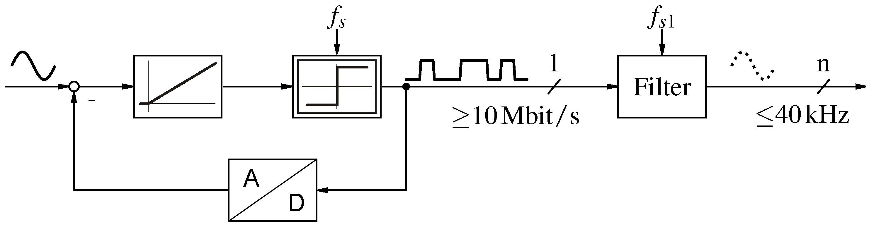
Signal processing based on bit-streams requires an understanding of the operation of -modulators. In a classical AD-conversion setup an -analog-to-digital converter is comprised of two elements; i.e., the -modulator and a low-pass filter with decimation, as shown in Figure 1. By omitting the low-pass filter and directly operating on the high-frequency (≥10 Mbit/s) bit-stream [5,6,7,8,9], a larger small signal bandwidth is achieved, e.g., in control loops.
The -modulator is composed of one or several integrators and a clocked comparator with feedback loops and gains. The order of the -modulator is specified by the number of implemented integrators; for example, in Figure 1 a first-order -modulator is shown. While first-order -modulators are always stable, for higher-order -modulators the feedback coefficients to individual stages have to be designed carefully to stabilize the feedback loops [10]. Several design methods are known from the literature [11,12]. For the presented evaluation, second-order -modulators are used.
Considered as a closed control loop, the -modulator integrates the control error between the input signal and the output signal. If this integral is greater than zero, it outputs a one, else a zero for the next clock cycle. In conjunction with the feedback loop, this simple control law ensures that the output bit-stream only consists of ones and zeros representing the input signal in average. As the bit-stream can only transport 1 bit information per clock cycle, quantization noise is introduced to the output bit-stream. Due to the internal structure, the -modulator provides noise shaping. As shown in Figure 2, the quantization noise is mainly shifted to the high-frequency signal components. In a classical digital signal processing (DSP) implementation, these are suppressed by a digital low-pass filter. In -signal processing (DSSP), this noise remains in the bit-streams and thereby influences the local distribution of ones and zeros.
The -modulators can be implemented in two ways. In a hardware -modulator, the integrator is an analog circuit and the feedback is a one-bit digital–analog-converter, whereas in a software -modulator the whole modulator is implemented digitally.
In general, there are two ways to map the logical values and , respectively 1 and 0, to normalized signal values: signed and unsigned. In the signed case, the logical 1 is mapped to 1 and the logical 0 is mapped to , whereas in the unsigned case the logical 0 is mapped to 0.
3. Logic Operations
There are four fundamental logic operations, NOT, AND, OR, and XOR, which can be applied on one or two bit-streams [13]. The logic operation NOT has one input (x), and the others require two inputs (, ). All fundamental logic operations have one output (y). The truth tables are shown in Table 1, Table 2, Table 3 and Table 4.
4. Statistical Analysis
Statistical analysis is applied in order to evaluate which mathematical functions are executed on the average value of bit-streams if fundamental logic operations are applied. The greatest difficulty for operations on -bit-streams is that no meaningful instantaneous value can be attributed to -bit-streams. As a substitute for the missing instantaneous value, many operations are designed on the average value over N samples, as this represents the actual value. The probability of ones in these samples is , where the index stands for either 1 or 2. For logical analysis, the expected number of ones () is an integer value, resulting in an integer value of zeros (). With rising sample size, the discretization step size of the probabilities decreases towards zero.
A statistical distribution of the positions of ones in the input bit-streams is assumed for the operations with two input bit-streams. This leads to the urn problem of type “drawing without replacement” for calculating the probability of ones in the output bit-stream [14].
4.1. NOT
The NOT operator inverts the bit-stream, leading to the probability . This is equivalent to a multiplication with −1 for bipolar inputs, as stated in [15]. Due to the fact that this connection is already known from the literature, the logical function NOT is not investigated any further.
4.2. OR
For the operation OR, each one in the first input bit-stream () and each one in the second input bit-stream () at the position of a zero in will lead to a one in the output bit-stream (y). Thus, the probability of ones in the output bit-stream is at least the probability of ones in the first input bit-stream. This can be written as
The distribution of ones in the output bit-stream is derived by the additional ones in the bit-stream, caused by , which have to be described. As the output bit-stream already consists of the ones of the first bit-stream, only the zeros of the first bit-stream can be conditionally converted to ones.
The number of combinatorial possibilities for a zero in the first bit-stream is given by
The possibilities to obtain t ones from the second input bit-stream in the place of zeros from the first input bit-stream are
This limits the possible amount of additional ones. The output bit-stream cannot have more ones than there are places in the output bit-stream and no more ones than the sum of ones in both input bit-streams. This leads to a maximum amount of additional ones in the output bit-stream, which can be expressed as
The probability of more ones in the output bit-stream is zero, as this event is not possible.
The probability for t ones from the second input bit-stream being combined with zeros of the first input bit-stream is given by
The remaining copied zeros of the first input bit-stream () also have to correspond to zeros in the second input bit-stream. The probability for this event can be expressed by
If the second input bit-stream has more ones than the first input bit-stream, the output bit-stream has at least the amount of ones in the second input bit-stream. This forms the lower boundary for the amount of additional ones in the output bit-stream. This can be expressed as
The limitations (4) and (7) ensure that the factorial is only calculated from values . The product of (2), (3), (5), and (6) in the limits (4) and (7) describes the probability of t additional ones from the second input bit-stream in the output bit-stream if the input bit-streams are processed by the logic operation OR. This can be written as
As a result, the probability of a one in the output bit-stream () is given by combining (1) and (8)
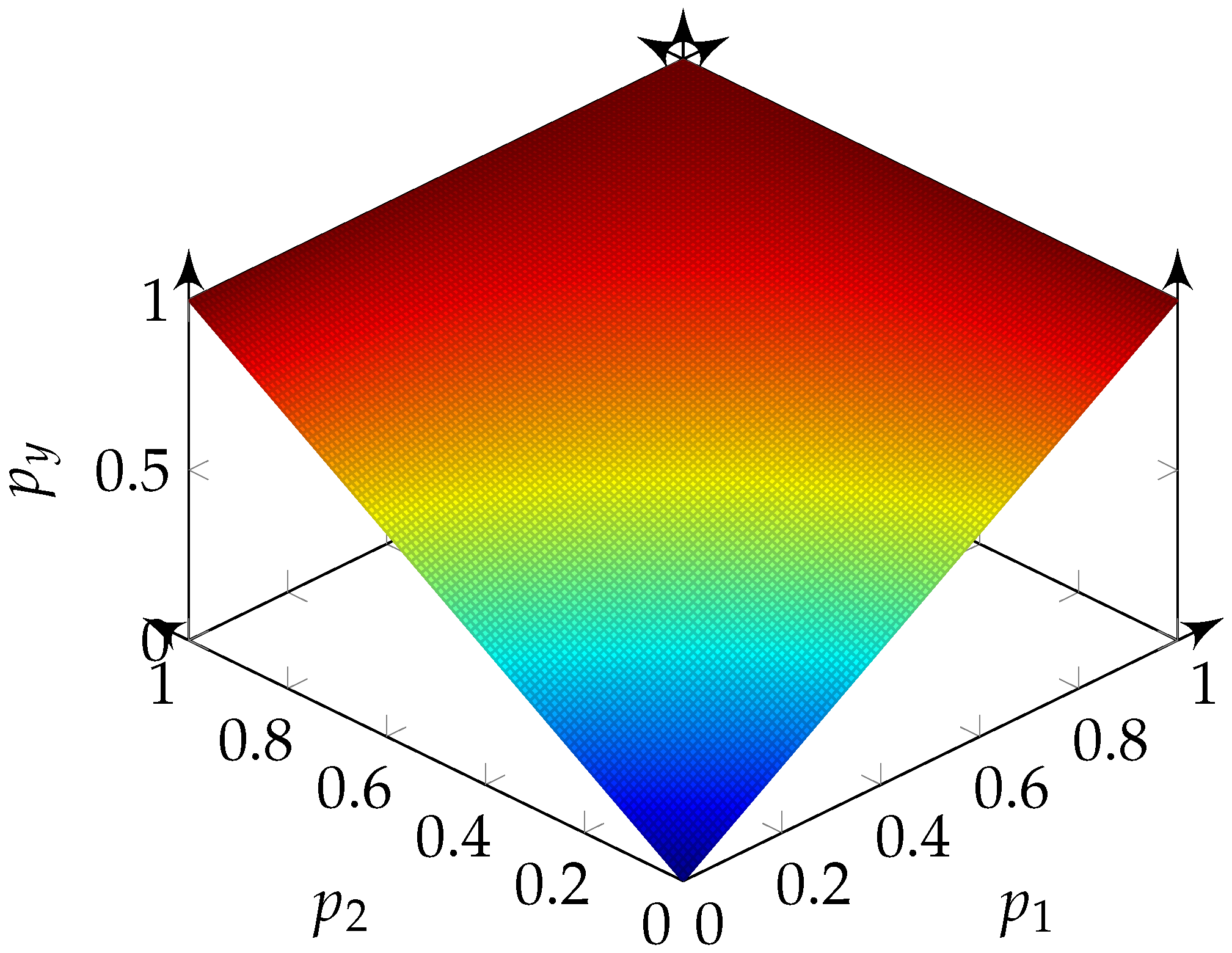
With (9) the probability of a one in the output bit-stream can be calculated for combinations of . Figure 3 illustrates the results for the logic operation OR.
4.3. AND
For the operation AND, each one in at the position of a one in leads to a one in y. Thus, the minimal number of ones in the output bit-stream results if the ones in are combined with zeros in and vice versa. The resulting ones—which cannot be combined with zeros—gives the minimal count of ones in the output bit-stream. These can be described by the ones, which are more than the length of the bit-stream
The maximal number of ones in the output bit-stream is the minimum of ones in one of the input bit-streams, as a one can only result if two ones are combined. This can be expressed as
For the description of the event, that two ones from both input bit-streams are in the same position, and the ones in the first bit-stream are taken into account. The number of combinatorial possibilities for a one in the first bit-stream is given by
The possibilities of arranging t ones from the second input bit-stream in the places of ones in the first input bit-stream are given by
The probability for t ones from the second input bit-stream to be in the same place as ones of the first input bit-stream can be described as
In the position of the other ones in the first input bit-stream should be zeros in the second input bit-stream. The probability for this is expressed by
The product of (12)–(15) with the limits (10) and (11) describes the probability of t ones in the output bit-stream, if the input bit-streams are processed by the logic operation AND
The probability of a one in the output bit-stream () follows from (16)
With (17) the probability of a one in the output bit-stream can be calculated for combinations of . Figure 4 illustrates the results for the logic operation AND.
4.4. XOR
For the operation XOR, a one in the output results if the inputs have opposite logical values in that position. As the logic operation XOR counts the differences in the bit-streams, only the probability of a one in the second input bit-stream combined with a zero in the first input bit-stream has to be described in order to calculate the amount of ones in the output bit-stream.
Thus, the minimal occurrence of this event is the difference between the ones in the second input bit-stream to the first input bit-stream, which is given by
The maximum number of ones of the second input bit-stream combined with zeros of the first input bit-stream is limited by the amount of ones in the second input bit-stream and by the amount of zeros in the first input bit-stream, resulting in
The operation XOR requires special precautions, as it is not possible to change the parity of ones (), with defined in Definition 1. As the statistical model does not regard this matter and returns for those events the same probability as for the events with the right parity, the probabilities of the events with different parities have to be set to zero. This can be achieved by multiplication with
Definition 1.
Let be a function of : .
First, the number of possibilities to place the zeros in the first input bit-stream is described, which can be expressed by
The possibilities of arranging t ones from the second input bit-stream in the places of zeros from the first input bit-stream can be described as
The probability of t ones from the second input bit-stream falling on the places of zeros in the first input bit-stream is given by
The other zeros of the first input bit-stream () should also be zeros in the second input bit-stream. The probability for this event can be expressed by
The product of (21)–(24) and the parity check (20) with the limits (18) and (19) leads to the probability for t events of this kind, which can be expressed as
The probability of a one in the output bit-stream () can be calculated. As the count of ones in the second input bit-stream combined with zeros from the first input bit-stream is known as t, the output bit-stream must contain t ones. The remaining zeros from the first input bit-stream are combined with zeros from the second bit-stream. These do not add ones to the output bit-stream. More ones in the output bit-stream can be added by the ones in the first input bit-stream if they match zeros in the second input bit-stream. This event will occur for all ones in the first input bit-stream () minus the resulting ones in the second input bit-stream (), as t ones from the second input bit-stream are already combined with zeros from the first input bit-stream. This can be described as
The probability of ones in the output bit-stream can be derived from (25) and (26)
With (27), the probability of a one in the output bit-stream can be calculated for combinations of . Figure 5 illustrates the results for the logic operation XOR.
With the Equations (9), (17), and (27), a distribution of ones in the output of a logical operation for independent bit-streams can be derived. In the next section, mathematical functions for the expected probability of ones in the output bit-stream depending on the probability of ones in the input bit-streams are presented.
5. Mathematical Operations
In order to utilize the fundamental logic operations as mathematical operations for -signal processing (DSSP), a mathematical function creating the same mapping of input values to output values must be fitted.
The statistical description developed in Section 4 leads to an expectation of ones in the output bit-streams of the logical operations OR, AND, and XOR for the input bit-streams with the probability . As stated in Section 4, the value represented in a bit-stream can be interpreted by averaging. The expected percentage of ones in N sampled bits from a bit-stream contains the same information as the averaged value, as it represents the average probability. Thus, the expected percentage of ones in the bit-stream is directly linked to the represented value.
With the numerical interpretation of the input and output bit-streams, as presented in Section 2, mathematical functions can be fitted to the transformation of the logic operations.
5.1. OR
In Figure 3, the percentage of ones in the output bit-stream of the logical operation OR is shown for different probabilities of ones in the input signals and . If or contain only zeros, the output value has a linear dependency on the probability of ones in the other input. This leads to the term . To match the flat boarder at only ones for or , the value represented by the output must be reduced by the value represented by the other input. One way to achieve this is to subtract , as the other input is only ones and is therefore mapped to one. Summed up, the unipolar mathematical function concludes. This function forms the same image, e.g., Figure 6.
5.2. AND
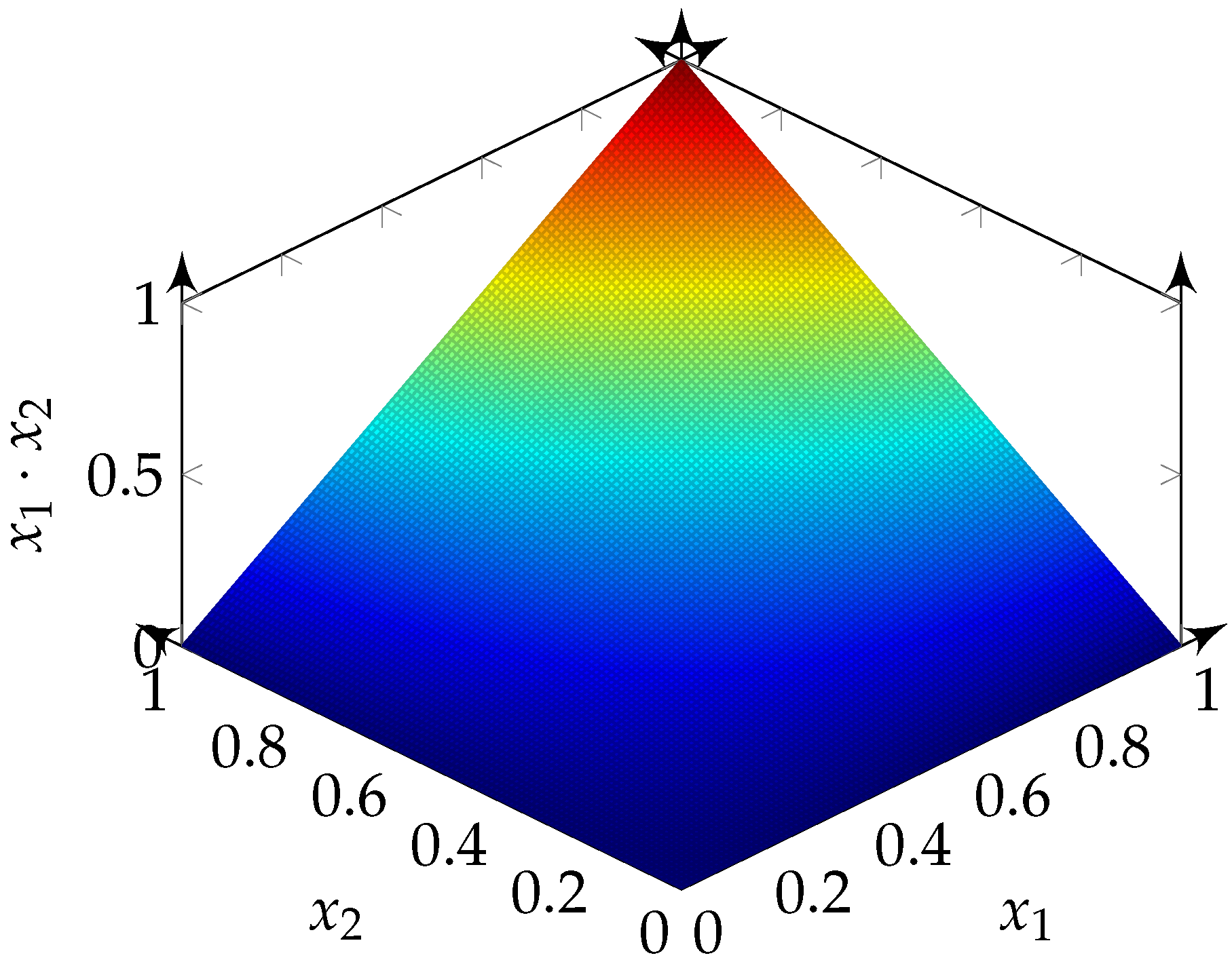
In Figure 4, the percentage of ones in the output bit-stream of the logical operation AND is shown for different probabilities of ones in the input signals and . For any input consisting of only zeros, the output is only zeros. For an input consisting of only ones, the output has a linear dependency on the probability of ones of the other input. This leads to the unipolar mathematical function . The expected probability of ones compared to Figure 7 reveals that they form the same image.
5.3. XOR
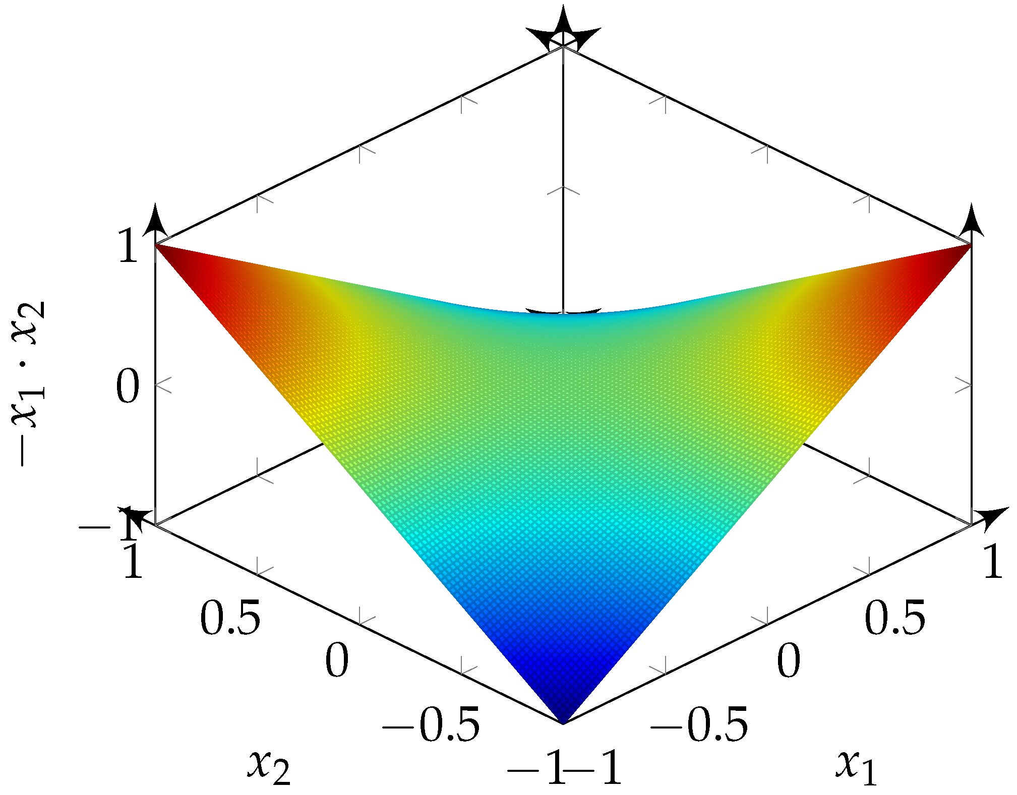
In Figure 5 the percentage of ones in the output bit-stream of the logical operation XOR is shown for different probabilities of ones in the input signals and . In this case, a flat cross at is revealed for or equal . This behaviour matches the interpretation that equals zero and the bipolar function is . Furthermore, there is always a linear dependency on the probability of ones in one input if the other input is constant zeros or ones. The maxima occur when the bit-streams are different, and the minima occur if they are equal. This is expected for a multiplication, but the maxima and the minima are interchanged, thus leading to the bipolar function . The figure of the bipolar function is similar to the image of the percentage of ones in the output bit-stream of the logical operation XOR (e.g., Figure 8).
Concerning the average values, the resulting functions can be written as
6. Prediction of the Standard Deviation
The intention is to utilize these functions in DSSP. Therefore, not only the average value has to be considered, but the standard deviation is also of interest, as it can be used as a measure for the image quality of the function. Thus, the standard deviation is discussed in this section.
The standard deviation must always be considered in the statistics for the mean value; in this case, it may also be used as a measure for the image quality of the derived mathematical function. According to the laws of logic, the standard deviation is calculated by [16]:
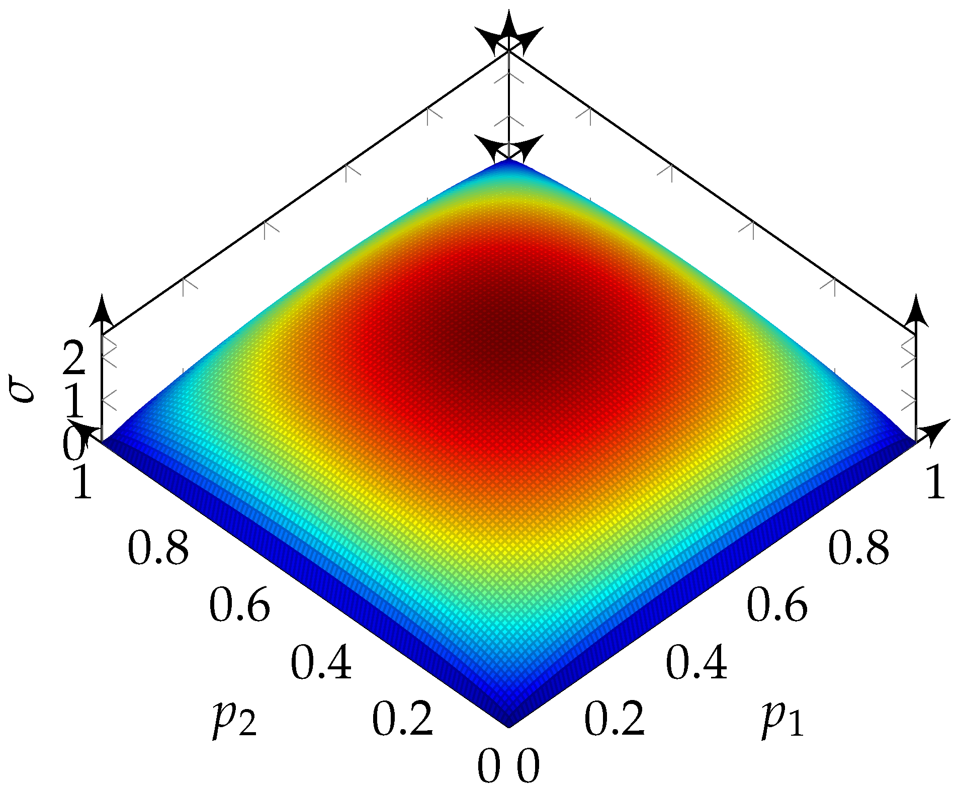
Based on (31), the distribution of the results from the logical operations can be calculated. For the logic operations OR and AND, the standard deviations are the same. This is shown in Figure 9.
For the logic operation XOR, the standard deviation is doubled in comparison to the operations OR and AND. The standard deviation of the operation XOR is shown in Figure 10.
As can be seen, the shape of the standard deviation is the same for all three logic operations. There are no combinatorial possibilities at the edges of the displayed plane, because at least one bit-stream () consists only of zeros or ones. Therefore, it can be reasoned that the result depends only on the probability of the other bit-streams. In the middle of the area (where both bit-streams consist of half ones and half zeros), there are—as expected—the most combinatorial possibilities. If, in extreme cases, the ones of one bit-stream coincide with the ones of the other bit-stream, the logical operations OR and AND result in output bit-streams corresponding to the input bit-streams. For the logical operation XOR, a bit-stream containing only zeros is the output bit-stream. In the other extreme case, if the ones of one bit-stream fall on the zeros of the other bit-stream, an output bit-stream of zeros results for the logical operation AND. For the logical operations OR and XOR, an output bit-stream consisting of ones results. For all other combinations of probabilities, at least one combination cannot be changed. Therefore, the largest standard deviations can be expected at this point. Due to the fact that the output bit stream changes from zero to one with XOR and only from 0.5 to zero or one with OR and AND, the scaling is expected to be a factor of two of the standard deviations from OR and AND to XOR. This leads to the expectation that the image quality is very good at the definition limits of the input values in the number space and gets worse at the center.
In review, the influence of the logic operations OR, AND, and XOR on the mean value of two input bit-streams with independent high-frequency components to the output bit-stream and the standard deviation of these operations are discussed.
7. Quantization Noise
In this section, the independence of the quantization noise—which results in the high-frequency signal components—of two bit-streams will be discussed.
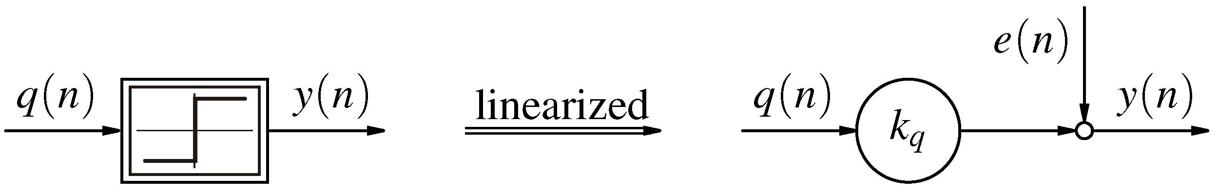
The mean value and the standard deviation have been discussed for statistical distributed bit-streams. This assumption is based on the linear model of the -modulator (i.e., Figure 11) [17].
As shown in previous publications [6,10,17,18,19], this assumption is quite common. In the case of non-linear DSSP, the assumption of a white noise source is bold, as the single bits at each clock cycle have an impact on the output bit-stream, whereas the white noise source assumption is more appropriate for a larger time scale. Therefore, the noise sources of the utilized -modulators must be independent, or the discussed probabilities are invalid.
The high-frequency quantization noise is able to interchange the positions of ones and zeros locally in the bit-stream, but will not affect the overall ratio. Thus, the independence of the noise between two bit-streams representing the same signal can be approximated by the normed cross-product without shift (32) using the signed mapping of the bit-streams.
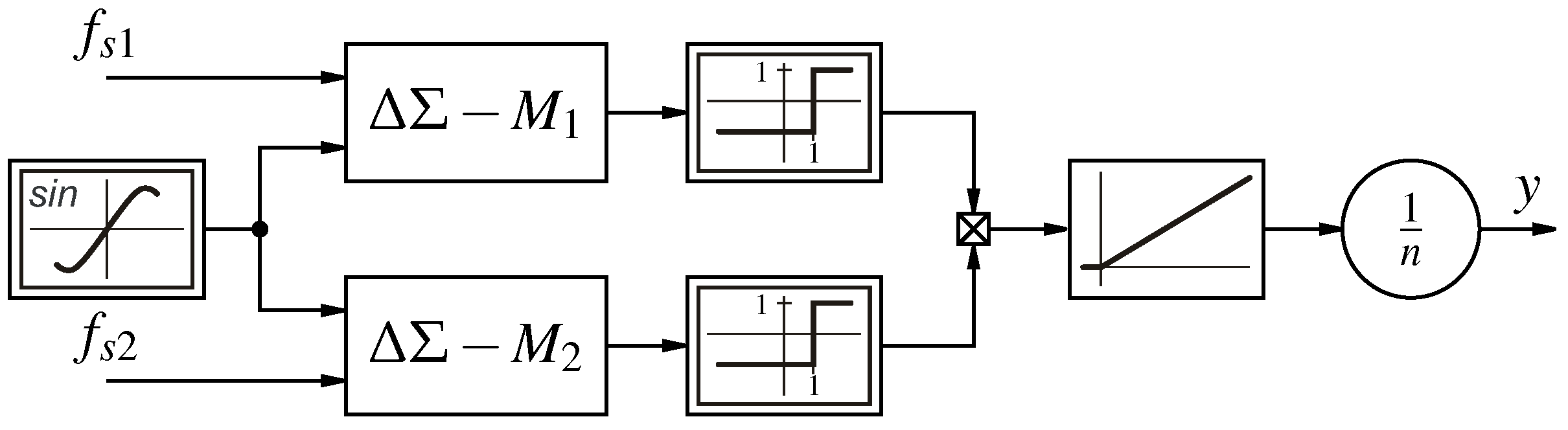
The evaluation of the presented approaches for modifying the high-frequency signal components are examined with a sinusoidal excitation in simulation, as shown in Figure 12.
The intention is to measure the independence of the two signals; therefore, lower values of are preferable. Especially for two software -modulators, which are created from logic cells in a field-programmable gate array (FPGA), driven by the same clock with the same parameter set and zero input value . This behaviour is expected, as the main noise source is the quantization. Since the modulator is a non-linear operator, this behaviour can change with different input signals. However, it is not guaranteed that the input signals are different for all load points of the plant, or if both signals are mapped to independent input ranges, the usable data range is significantly reduced and the result must be processed further. Another opportunity is to use different designs for the -modulators [7] (e.g., [10,12]). With this combination, . The last evaluated possibility to overcome this issue is utilizing different clock rates of the -modulators (), which leads to different bit-streams. For a second-order -modulator with minimal parameters [12] and follows . This option has the drawback that the overall system clock has to be faster than necessary for the requested bandwidth.
For different modulator design combinations, it can be possible to reach a higher independence of the high-frequency noise signal components. Therefore, the proposed solution is to utilize differently designed -modulators, since the investigated implementations have the lowest of all the proposed solutions.
8. Validation of the Results
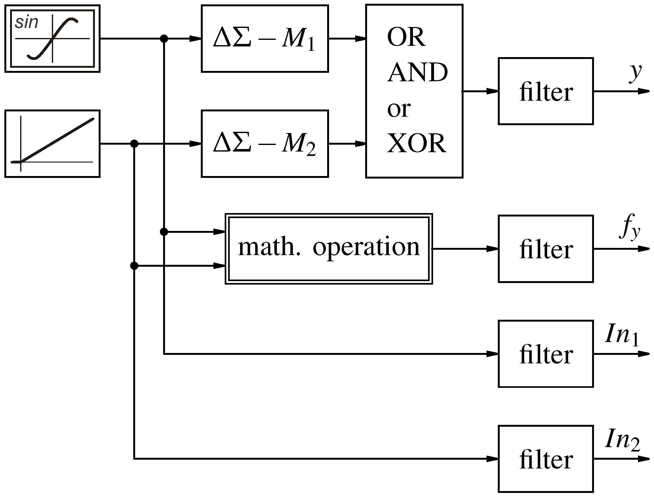
The testbench in Figure 13 modulates the input signals with two different designed -modulators. The resulting bit-streams are fed into a dual input logic operation (AND, OR, or XOR) and filtered with an sinc filter [10]. The resulting multibit value is compared against the sinc filtered multibit value of the corresponding multibit mathematical operation. For the unipolar functions AND and OR, unipolar signal sources and -modulators are used, and the bipolar function XOR is driven by bipolar input signals with bipolar -modulators.
The input sources are chosen as shown in Figure 13. The phase shift for the sinus source (Input) and the delay followed by an overshoot by the ramp input (Input) is due to the sinc filter.
The functional relation for OR and AND are proven in simulation (e.g., Figure 14). Nevertheless, the greatest deviations occur not in the region around , where they are estimated from the considerations in Section 6. The resulting value for the logic operation OR deviates the most around and the logic function AND in the mirrored region around . This fact shows the necessity of evaluating the deviation for different -modulator implementations on a testbench with the expected input signals.
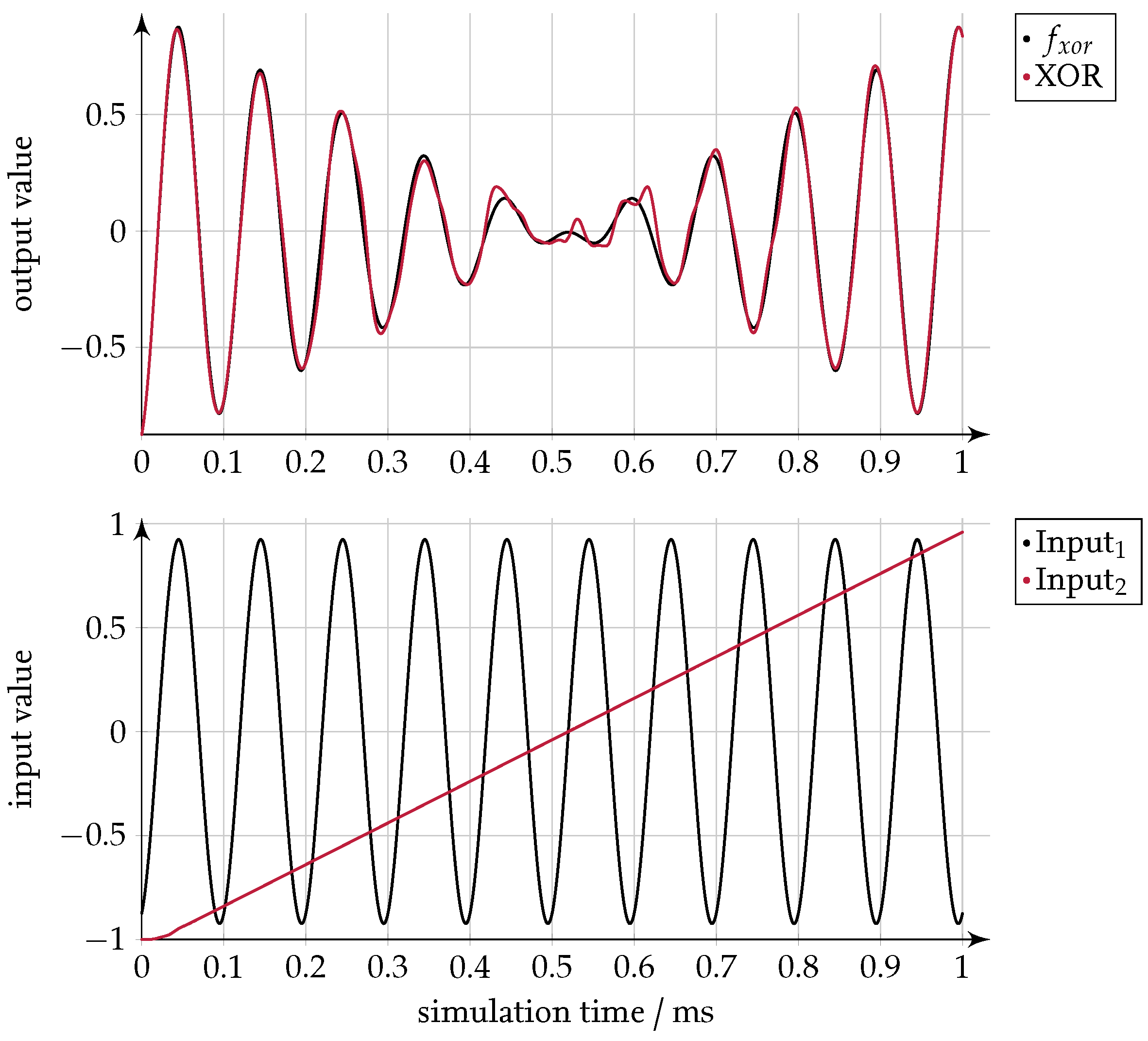
The result in Figure 15 for the logic function XOR shows the expected behaviour. For input signals at the definition boarder (e.g., the beginning and the ending of the simulation), the represented value in the output bit-stream follows the expected signal. The deviations are most severe when both input signals represent a value in the middle of the definition range, which occurs in the range around .
The simulation results show that the statistical considerations are valid. The resulting deviations are lower than expected from the calculated mean deviations. In order to use the logic operations as mathematical functions, the implementation of the -modulators must be verified using the expected input signals.
9. Conclusions
In this publication, the results of the fundamental logic operations NOT, AND, OR, and XOR on bit-streams are investigated and interpreted statistically. The operation NOT represents a negation for a bipolar input signal. The operation AND results in the product for unipolar input signals. The operation OR results in the addition of the input signals minus the product for unipolar input signals. The operation XOR results in the negative product for bipolar input signals. All operations with multiple inputs have in common that the standard deviation reaches a minimum for input values at the border and a maximum for values in the center of the input range. As the results are based on the assumption of input bit-streams with independent high-frequency components, multiple optimisation strategies for decoupling the quantization noise are discussed and evaluated. The best-rated solution is to implement different designs for the -modulators; for example, [10,12]. This combination has been simulated for all three dual input logic operations (AND, OR, XOR). The deviation between the filtered output bit-streams and the filtered functions show better results than expected from the standard deviation, and support the previous theses. In order to achieve the best independence of the high-frequency signal components, different designs must be evaluated with the expected input signals.
Conflicts of Interest
The author declares no conflict of interest.
Abbreviations
The following abbreviations are used in this manuscript:
| DSP | digital signal processing |
| DSSP | -Signal Processing |
| NOT | logic function not |
| OR | logic function or |
| AND | logic function and |
| XOR | logic function xor |
| FPGA | Field Programmable Gate Array |
References
- Lagoyannis, D.; Pekmestzi, K. Multipliers of delta-sigma sequences. Radio Electron. Eng. 1981, 51, 281–286. [Google Scholar] [CrossRef]
- Kouvaras, N. Operations on delta-modulated signals and their application in the realization of digital filters. Radio Electron. Eng. 1978, 48, 431–438. [Google Scholar] [CrossRef]
- Zrilic, D.G. Circuits and Systems Based on Delta Modulation: Linear, Nonlinear and Mixed Mode Processing; Springer: Berlin/Heidelberg, Germany, 2005. [Google Scholar]
- Ng, C. Bit-Stream Signal Processing on FPGA. Ph.D. Thesis, University of Hong Kong, Hong Kong, China, 2008. [Google Scholar]
- Homann, M. Hochdynamische Strom- und Spannungsregelung von Permanenterregten Synchronmaschinen auf Basis von Delta-Sigma Bitströmen. Ph.D. Thesis, TU Braunschweig, Braunschweig, Germany, 2016. [Google Scholar]
- Homann, M.; Klein, A.; Kirchner, R.; Schumacher, W. Quasi-kontinuierliche Signalverarbeitung mit Delta Sigma Bitströmen in der Antriebstechnik—Ein Überblick. In Proceedings of the Fortschritte in der Antriebs- und Automatisierungstechnik, Stuttgart, Germany, 27 April 2016; pp. 215–227. [Google Scholar]
- Homann, M.; Klein, A.; Schumacher, W. Direct Delta Sigma Signal Processing for Control of Power Electronics. In Proceedings of the International Exhibition and Conference for Power Electronics, Intelligent Motion, Renewable Energy and Energy Management (PCIM), Nuremberg, Germany, 10–12 May 2016. [Google Scholar]
- Homann, M.; Schumacher, W. High Bandwidth Phase Voltage and Phase Current Control Loop of a Permanent Magnet Synchronous Motor based on Delta Sigma Bitstreams. In Proceedings of the 18th European Conference on Power Electronics and Applications (EPE’16 ECCE Europe), Karlsruhe, Germany, 5–9 September 2016. [Google Scholar]
- Kershaw, S.M.; Sandler, M.B. Digital signal processing on a sigma-delta bitstream. In Proceedings of the IEE Colloquium on Oversampling Techniques and Sigma-Delta Modulation, London, UK, 30 March 1994. [Google Scholar]
- Schreier, R.; Temes, G.C. Understanding Delta-Sigma Data Converters; IEEE Press: Piscataway, NJ, USA, 2005. [Google Scholar]
- Schreier, R. Delta Sigma Toolbox. Available online: http://www.mathworks.com/matlabcentral/fileexchange/19-delta-sigma-toolbox (accessed on 21 June 2017).
- Marques, A.; Peluso, V.; Steyaert, M.S.; Sansen, W.M. Optimal parameters for ΔΣ modulator topologies. IEEE Trans. Circuits Syst. II Analog Digit. Signal Process. 1998, 45, 1232–1241. [Google Scholar] [CrossRef]
- Wolfgang Rautenberg. Einführung in Die Mathematische Logik; Vieweg + Teubner: Wiesbaden, Germany, 2008. [Google Scholar]
- Bernoulli, J.; Huygens, C. Wahrscheinlichkeitsrechnung (Ars Conjectandi); University of Michigan Library: Ann Arbor, MI, USA, 1899; Volume 2. [Google Scholar]
- O’Leary, P.; Maloberti, F. Bit stream adder for oversampling coded data. Electron. Lett. 1990, 26, 1708–1709. [Google Scholar] [CrossRef]
- Rüschendorf, L. Mathematische Statistik; Springer-Lehrbuch Masterclass, Springer Spektrum: Berlin, Germany, 2014. [Google Scholar]
- Ortmanns, M.; Gerfers, F. Continuous-Time Sigma-Delta AD Conversion: Fundamentals, Performance Limits and Robust Implementations; Springer Series in Advanced Microelectronics; Springer: Berlin, Germany, 2006; Volume 21. [Google Scholar]
- Ardalan, S.H.; Paulos, J.J. An analysis of nonlinear behavior in delta-sigma modulators. IEEE Trans. Circuits Syst. 1987, 34, 593–603. [Google Scholar] [CrossRef]
- Reiss, J.D. Understanding Sigma-Delta Modulation: Solved and Unsolved Issues. J. Audio Eng. Soc. 2008, 56, 49–64. [Google Scholar]
Figure 1.
First-order -modulator with low-pass filter.

Figure 2.
Power of the noise transfer function (NTF) of a first-order -modulator [10].
Figure 2.
Power of the noise transfer function (NTF) of a first-order -modulator [10].
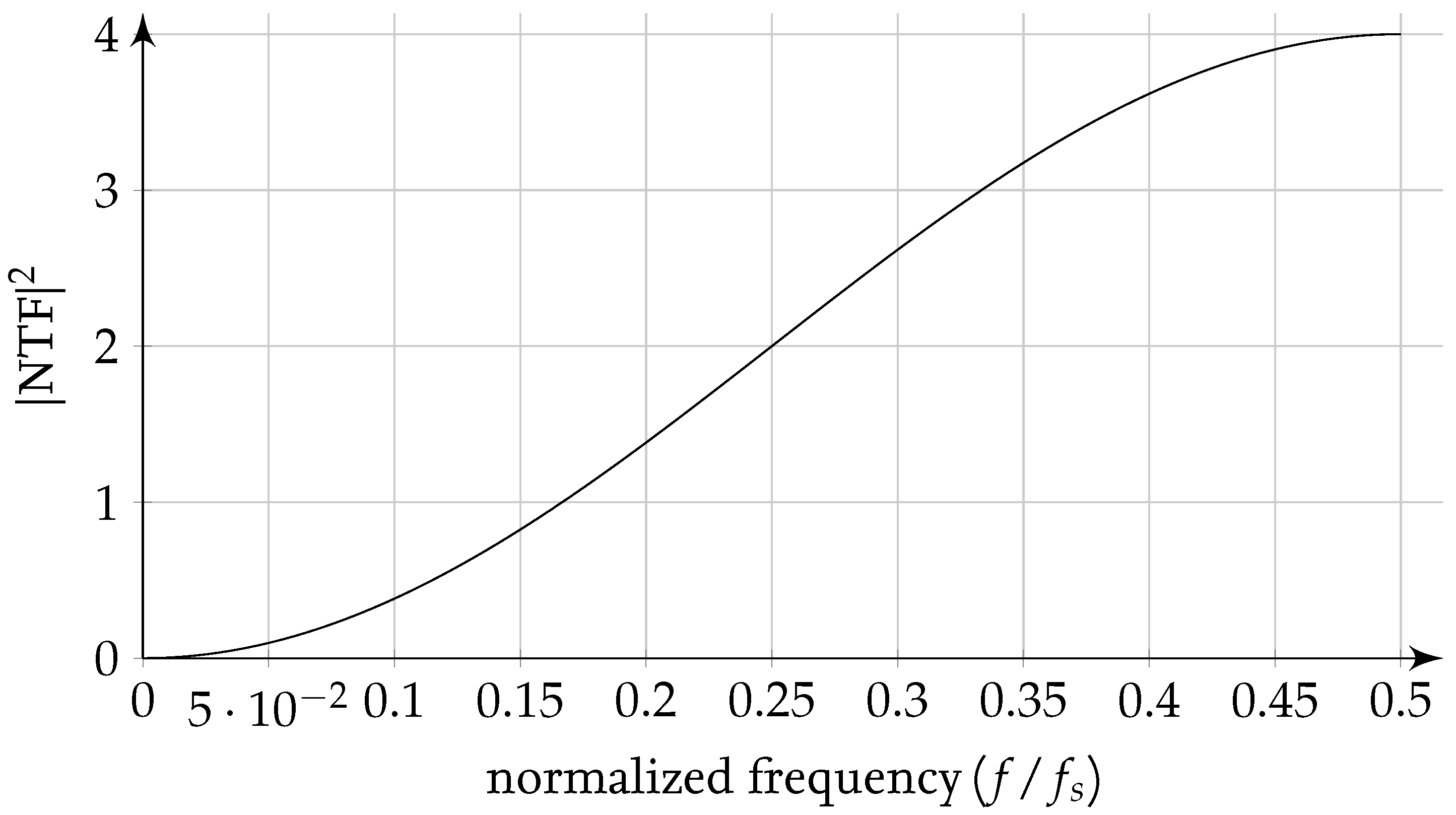
Figure 3.
Expected probability of a one in the output bit-stream for the input bit-streams and , with the probability of ones , operated by OR.
Figure 3.
Expected probability of a one in the output bit-stream for the input bit-streams and , with the probability of ones , operated by OR.

Figure 4.
Expected probability of a one in the output bit-stream for the input bit-streams and , with the probability of ones , operated by AND.
Figure 4.
Expected probability of a one in the output bit-stream for the input bit-streams and , with the probability of ones , operated by AND.

Figure 5.
Expected probability of a one in the output bit-stream for the input bit-streams and , with the probability of ones , operated by XOR.
Figure 5.
Expected probability of a one in the output bit-stream for the input bit-streams and , with the probability of ones , operated by XOR.
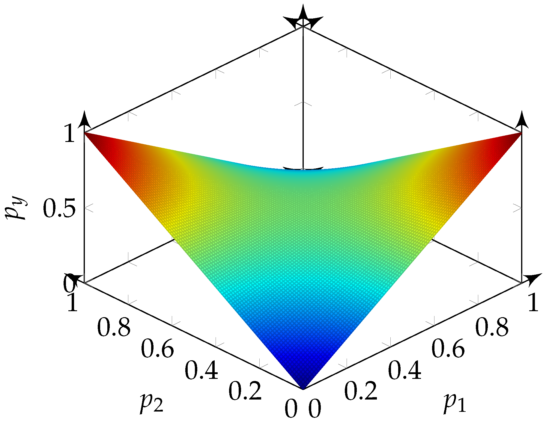
Figure 6.
Results of the function .
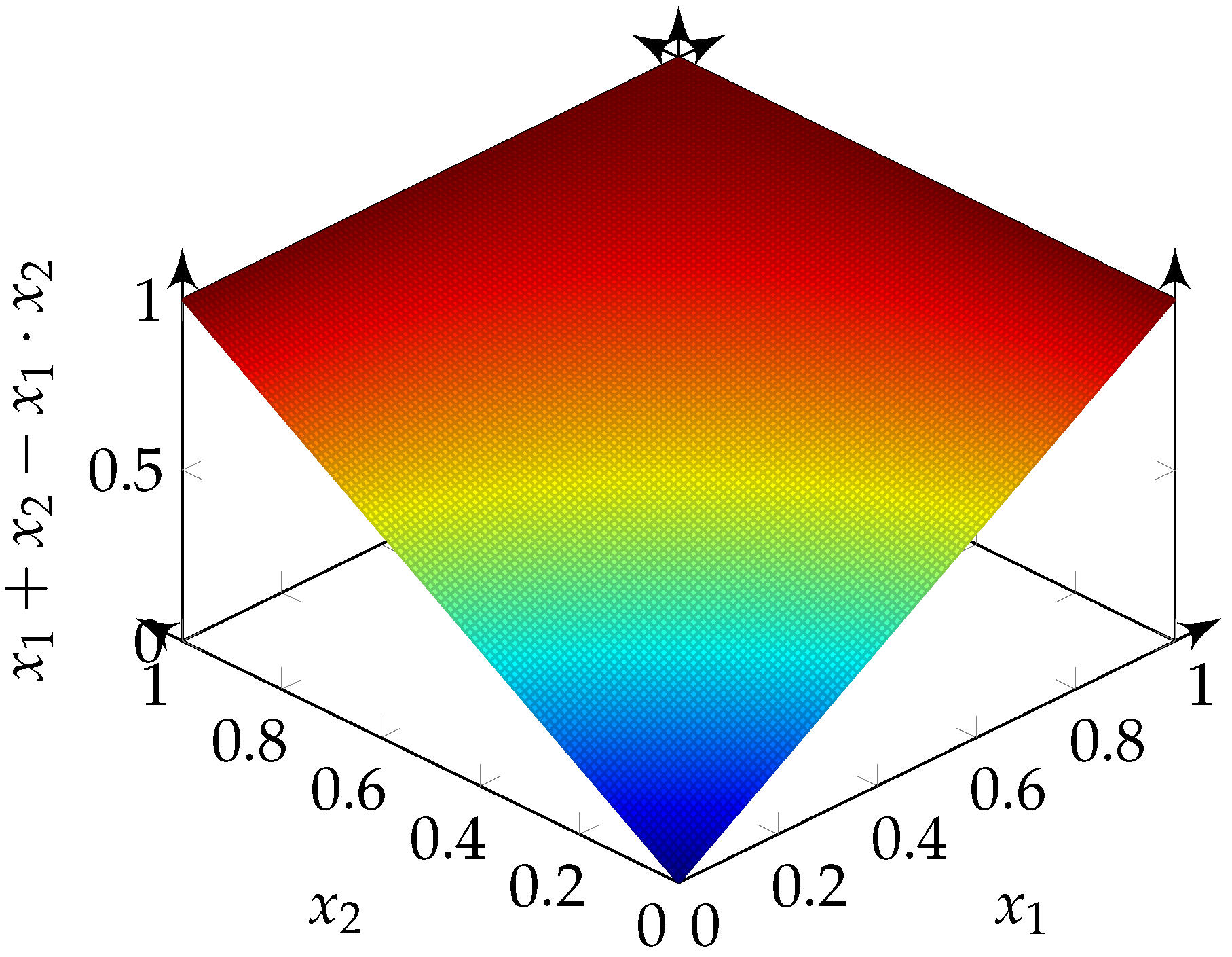
Figure 7.
Results of the function .

Figure 8.
Results of the function .

Figure 9.
Standard deviation for the event of a one in the output bit-stream for the input bit-streams and , with the probability of ones , operated by OR or by AND.
Figure 9.
Standard deviation for the event of a one in the output bit-stream for the input bit-streams and , with the probability of ones , operated by OR or by AND.

Figure 10.
Standard deviation for the event of a one in the output bit-stream for the input bit-streams and , with the probability of ones , operated by XOR.
Figure 10.
Standard deviation for the event of a one in the output bit-stream for the input bit-streams and , with the probability of ones , operated by XOR.
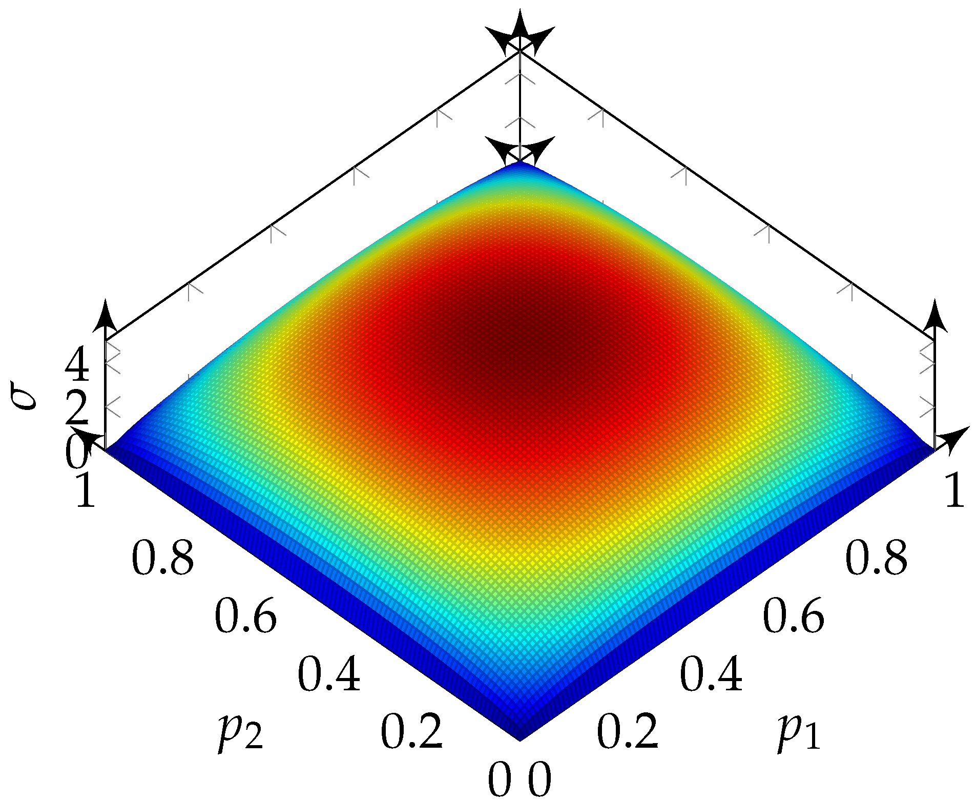
Figure 11.
Linear model of the quantizer utilized in a -modulator comprised of a gain () and a white noise source () [17].
Figure 11.
Linear model of the quantizer utilized in a -modulator comprised of a gain () and a white noise source () [17].

Figure 12.
Testbench for evaluating the independence of the noise from -modulators.

Figure 13.
Testbench for evaluating the logic functions.

Figure 14.
Results from the testbench for the logic operations OR and AND and corresponding operations and .
Figure 14.
Results from the testbench for the logic operations OR and AND and corresponding operations and .
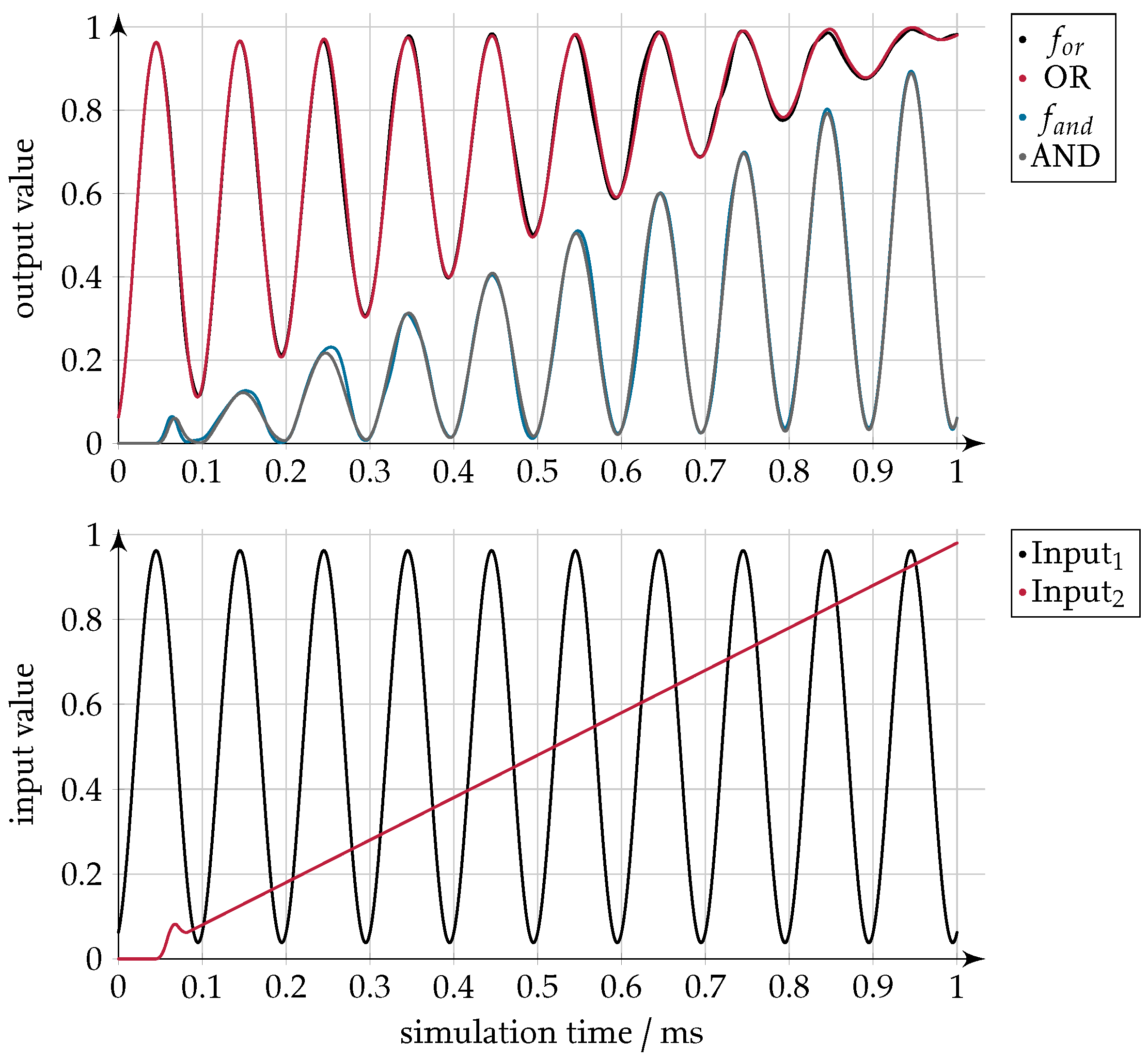
Figure 15.
Results from the testbench for the logic operation XOR and the float operation .


Table 1.
Truth table for NOT.
| x | y |
|---|---|
| 0 | 1 |
| 1 | 0 |
Table 2.
AND.
| y | ||
|---|---|---|
| 0 | 0 | 0 |
| 0 | 1 | 0 |
| 1 | 0 | 0 |
| 1 | 1 | 1 |
Table 3.
Truth table for OR.
| y | ||
|---|---|---|
| 0 | 0 | 0 |
| 0 | 1 | 1 |
| 1 | 0 | 1 |
| 1 | 1 | 1 |
Table 4.
Truth table for XOR.
| y | ||
|---|---|---|
| 0 | 0 | 0 |
| 0 | 1 | 1 |
| 1 | 0 | 1 |
| 1 | 1 | 0 |
© 2018 by the author. Licensee MDPI, Basel, Switzerland. This article is an open access article distributed under the terms and conditions of the Creative Commons Attribution (CC BY) license (http://creativecommons.org/licenses/by/4.0/).
Share and Cite
MDPI and ACS Style
Klein, A. Logic Operators on Delta-Sigma Bit-Streams. Math. Comput. Appl. 2018, 23, 4. https://doi.org/10.3390/mca23010004
AMA Style
Klein A. Logic Operators on Delta-Sigma Bit-Streams. Mathematical and Computational Applications. 2018; 23(1):4. https://doi.org/10.3390/mca23010004
Chicago/Turabian StyleKlein, Axel. 2018. "Logic Operators on Delta-Sigma Bit-Streams" Mathematical and Computational Applications 23, no. 1: 4. https://doi.org/10.3390/mca23010004