Article

On Appearance of Fast or Late Self-Synchronization between Non-Ideal Sources Mounted on a Rectangular Plate Due to Time Delay

by
Armand Anthelme Nanha Djanan
1,*,
Steffen Marburg
2 and
Blaise Roméo Nana Nbendjo
1
1
Laboratory of Modelling and Simulation in Engineering, Biomimetics and Prototypes and TWAS Research Unit, Faculty of Sciences, University of Yaounde I, Yaounde P.O. Box 337, Cameroon
2
Chair of Vibro-Acoustics of Vehicles and Machines, Department of Mechanical Engineering, Technical University of Munich, 80333 Munich, Germany
*
Author to whom correspondence should be addressed.
Math. Comput. Appl. 2022, 27(2), 20; https://doi.org/10.3390/mca27020020
Submission received: 24 December 2021 / Revised: 17 February 2022 / Accepted: 19 February 2022 / Published: 24 February 2022

Abstract

:
The present paper aims to present the effects of late switching on (time delay) between two or three DC electrical machines characterized by limited power supplies on their fast or late self-synchronization when mounted on a rectangular plate with simply supported edges. The DC electrical machines are considered here as non-ideal oscillators, rotating in the same direction and acting as an external excitation on a specific surface of the plate. The stability analysis of the whole studied system (with two machines) around the obtained fixed point is done through analytical and numerical approaches by using the generalized Lyapunov and Routh-Hurwitz criterion. The existence conditions of the fixed point and the stability conditions are derived and presented. Great attention is put on the incidence of such study on the vibrations amplitude of the plate, which are considerably reduced in some cases. It appears that the time delay induces a rapid or late synchronization observed between the DC sources. This has been observed by numerically exploring the dynamics of the system for various possibilities that could occur. Moreover, in the modelling of the system, the positions on the plate occupied by DC electrical machines are taken into account by using the Heaviside function. It is shown that, in the case of three DC electrical machines, these positions influence the time to obtain a synchronous state between the DC electrical machines.

1. Introduction

The development of countries passes through the revolution of industries and the construction of some infrastructures. Thus, civil and mechanical engineering are main disciplines, which should be well mastered in order to achieve this goal. Over many years, various researchers have contributed to this field of research and some of their results have improved the technology used today [1,2]. At present, on the one hand, we have rotating machines [3,4] used in industry to increase the output, to avoid human physical effort and to easily realize some tasks. On the other hand, the presence of bridges, buildings, aircraft, platforms, etc. help us in the developing process. The exploration of dynamic responses of mechanical structures, such as rectangular plates, is interesting and important, as some of the results may be applicable in understanding the dynamic behavior of structures and buildings [5,6]. We frequently encounter rectangular plates in several domains, such as civil and mechanical engineering. They are often present in industry, aircraft, and marine structures, where they are extensively used. This type of mechanical structure is regularly subjected to various types of external excitations during their use [7,8]. These excitations could be caused by some natural phenomenon, such as wind and earthquakes [9] or provoked by some human or mechanical actions coming from other structures, such as rotating machines [3,4]. In each case, we could assist a premature destruction of the system. A system is said to be a non-ideal one when the voltage supply to a DC electrical machine is limited or when the exciter (DC electrical machine) is influenced by the response of the system (mechanical structure).
While supplied with a DC voltage, the previously DC electrical machines become unbalanced when we fixed an eccentric mass at a distance r from their rotors axis. Thus, the unbalanced DC electrical machine induces mechanical vibration to the rectangular plate, which will simultaneously influence the rotational displacement of the unbalanced mass. Therefore, we note that the excitation is influenced by the main response of the system. This less-encountered phenomenon in vibration theory appears only in a non-ideal vibrating system.
In the current literature, the dynamic behavior of ideal vibrating systems no longer needs to be presented. Nevertheless, today there are only few results on non-ideal systems. Thus, Balthazar et al. [10] presented progress of such a problem. The first results of the non-ideal systems show that the passage through the resonance sometimes requires more input power than the driven dynamical system has available. In the last decade, non-ideal vibrating systems have been considered as a major challenge in theoretical and practical engineering research [11,12]. Due to this particularity, the external excitation is influenced by the main response of the system; therefore, non-ideal vibrating systems present one more degree of freedom.
Considering a DC electrical machine operating on an elastic structure, a certain input (power) is required to produce a certain output (machine rotating velocity), regardless of the motion of the structure. For non-ideal systems, this may not be the case. Hence, it is interesting to analyze what happens to the machine as the response of the system changes. Here, the excitation is always limited in two ways:
  • By the characteristic curves of the particular energy source
  • By the dependence of the motion of the system on the motion of the energy source.
However, coupling between the governing equations of the motion (structure) and the energy source then takes place. Today, many works have been done on non-ideal systems for better understanding of common phenomena occurring in mechanical sciences [13,14].
The large applications of electrical machines helped to revolutionize industry and eliminate animal and human efforts for tasks such as pumping water or handling grain. One can note additionally that a household of electrical machines significantly decreases hard labor at home and ameliorates more comfort and safety. When several rotating machines are mounted on flexible structures, they will inevitably exhibit non-linear vibrating behaviors. This is caused by the fact that such a vibrating system exhibits external excitation with a limited power supply [10,12,15]. The mathematical modelling of a non-ideal vibrating system leads to an supplementary dynamics equation compared to their counterpart ideal system. This describes and explains the interaction appearing between the DC electrical machine source and the rest of the system [10].
In industry, the production chain sometimes requires the action of several machines acting at the same time or with a delay on a mechanical structure [16,17]. Thus, it becomes important and interesting to focus on the dynamics of the machines and their impact on the structure where they are mounted. However, Balthazar et al. [16,17] explored the self-synchronization of two or four rotating machines with limited power supply supported by a simple portal frame. Their results lead them to conclude that we can observe the appearance of self-synchronization and a lack of synchronization between DC electrical machines for certain characteristics of the vibrating system. Recently, Czolczynski et al. [18,19] studied the synchronization phenomenon occurring between numerous rotating pendulums fixed on a horizontal beam moving longitudinally on a parallel surface to the beam by the mean of a viscoelastic device. They demonstrated that, after the initial transient movement, one can observe the different states of pendulums’ synchronization. The energy transfer between the pendulums is responsible for the synchronization, which occurs with time [18,19,20]. In this sense, Nanha et al. [21] show that two DC electrical machines with power supply limited and supported by a rectangular plate could synchronize with different values of the angular displacement shift of the DC electrical machines, such as zero, π , or 2 π , depending on the physical and mechanical properties of the electrical machines and the rectangular plate. In addition, they showed that we can observe a reduction of plate amplitudes of vibration when the phase difference between both DC electrical machines is equal to π . Such an observation was done earlier in the literature in other ideal problems, which were distinct from the present problems presented by Dimentberg et al. [22] and Bleckhman [23].
The self-synchronization phenomenon studied here allows the automatic coordination of exciters (through energy transferred between DC electrical machines) and is used in many vibratory machines for generating the required excitation force with constant or another required direction. Since self-synchronization of exciters is a phenomenon observed during a stationary state of the system, we aim to show in this paper what could be the effect of the delay in starting a DC electrical machine compared to others in the time to reach to a synchronous state between exciters. Thus, we focus on the influence of the time-delay to obtain the self-synchronization phenomenon between two or three DC electrical machines fixed on a rectangular plate. Through numerical simulations, we show how the position occupied by the electrical machines influences the synchronization. The analytical approach consists of the stability analysis of the whole system when the DC electrical machines are synchronized.
The main motivation of this research work is to show the effect of the time delay input of DC electrical machines to reach the synchronization state. We aim to show that the time delay input of the second motor considerably affects the time when the motors are synchronized, since self-synchronization happens earlier. Thus, we seek to prove that mechanical characteristics of the plate have an influence on the time to reach a synchronous state between the DC electrical machines. The stability analysis is displayed analytically and numerically with the purpose to predict the dynamics of the studied system.
The paper is organized as follows. Section 2 consists of the description, the presentation of the studied system, and describes how the mathematical modelling of the system is developed. In the Section 3 of the paper, we proceed to the direct numerical simulation of ODEs, describing the dynamics of the studied non-ideal system, and Section 4 presents the stability analysis. Section 5 presents some concluding remarks on the study.

2. Description of the Studied System and Mathematical Formalism

The present section aims to give a full description of the studied system with all the assumptions made, with the purpose to obtain a mathematical formalism presenting the dynamical equations of the system. All mathematical details useful for the comprehension are given in Appendix.
The mathematical formalism was built on the basis of the Hamilton principle, which required expressions of different types of energy occurring in the system [15]. Exploration of boundary conditions of the plate lead to obtaining the ordinary differential equation (ODE) of the studied system [21].

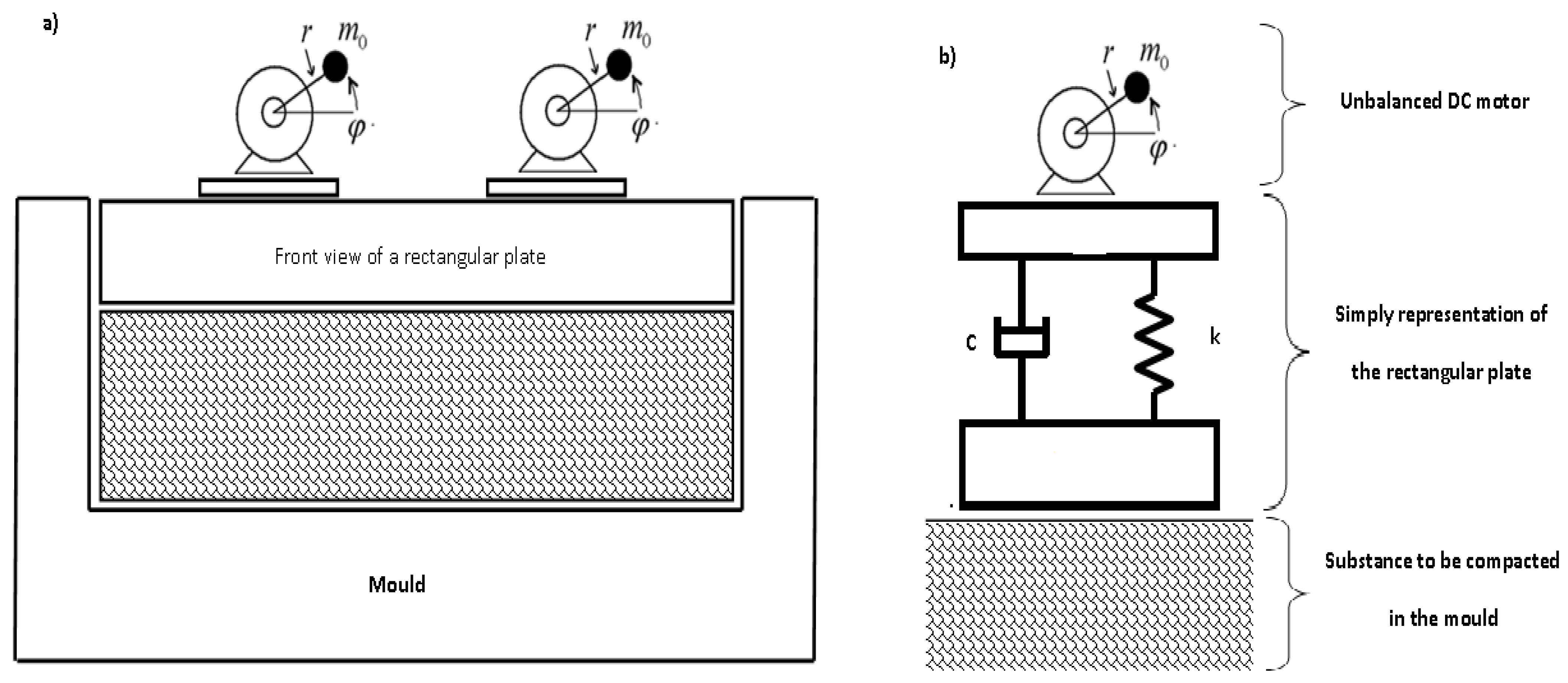
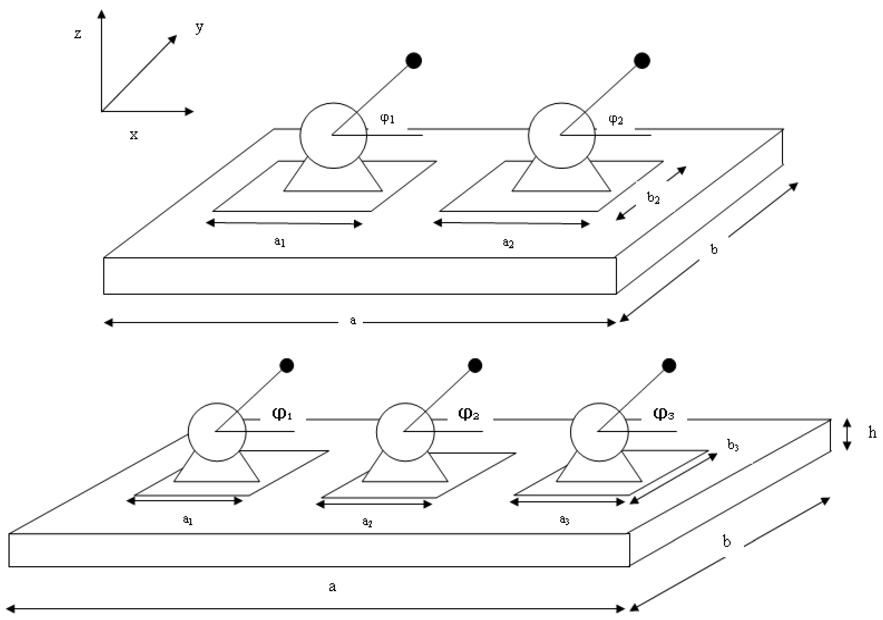
2.1. Presentation of the Studied Systems

The system was composed of a rectangular plate (with dimensions: length a, width b, and thickness h), where edges were simply supported. Here, two or three DC electrical machines carrying unbalanced masses on their shafts were fixed and regularly spaced on the plate. It was supposed that the electrical machines rest and act on a precise areas on the plate. In addition, the rectangular plate was responsible for bending and shearing displacements, but here, only transversal displacement was taken in account.
As an example of a non-ideal vibrating system in mechanical engineering, we mention a vibro-compacting machine composed by a mould supporting its top unbalanced DC electrical machines. A schematic of this device is shown in Figure 1 and Figure 2, and we display a set-up of the studied system of this paper.
The angular displacements of the DC electrical machines are denoted by φ i and the rotors have the inertia moment J i and carry the unbalanced masses m i situated at a distance r i from their axis, respectively (with i = 1 , 2 , 3 ). However, either from the manufacturer or from the experiments, the characteristic driving torque of a DC electrical machine for each given power level is assumed to be well known [16,24,25,26].

2.2. Mathematical Modelling

The PDEs describing the dynamics of the studied system are obtained from the Hamilton principle, which is carried by the writing of the different expressions of elastic potential and the external and the kinetic energies of the considered system [15,27,28,29]. Thus, in the case of a rectangular plate of length a, width b, and thickness h, with the density ρ , and a Young’s modulus E and a Poisson’s ratio ν , where a DC electrical machine with limited power supply is mounted, one obtains the following equations:
ρ h + i m i a b + M i 2 W t 2 + λ W t + E h 3 12 1 ν 2 4 W x 4 + 2 2 W x 2 2 W y 2 + 4 W y 4 = i H t t i × S x i × S y i × M i g + m i r i a b φ i t 2 sin φ i 2 φ i t 2 cos φ i , J i + m i r i 2 2 φ i t 2 T i φ i t + m i r i g cos φ i + m i r i 2 2 W t 2 cos φ i = 0 ,
where S x i = H ( x x 1 i ) H ( x x 2 i ) , S y i = H ( y y 1 i ) H ( y y 2 i ) , and i = 1 , 2 , 3 . W is the transversal displacement of the plate in the z-direction, t is the variable time, T i ( φ ˙ i ) represents the resulting momentum of each electrical machine, and λ is the damping coefficient. H is the step function, and x 1 i , x 2 i , y 1 i , and y 2 i are the coordinates indicating the position of the DC electrical machines on the plate. r i , m i , and M i are the eccentricity, the unbalanced mass, and the mass per unit of surface of the i electrical machine, respectively, while g is the intensity of the gravity and t i is the functioning delay imposed by the DC electrical machines.
Herein, the studied DC electrical machines are modelled by taking into account electrical features of a common electrical machine, such as the armature winding resistance R and the inductance L. The DC electrical machine presented results from our expectation that the electrical time constant L / R is small enough not to have a significant impact on the dynamics of the entire mechanical system (where L and R are the inductance and the resistance of the electrical machine, respectively). For this, the dynamical equation of the controlled torque is presented in Appendix A. The controlled torque of each unbalanced rotor is assumed to be of linear form by neglecting only the electrical machine inductance effect [16,24,25,26], and is presented as follows:
T i ( φ i ˙ ) = u 1 i v 2 i φ i ˙ , w i t h i = 1 , 2 o r 3 .
This mathematical modelling of the resulting torque of the DC electrical machines refers to an asynchronous AC electrical machine and the assumption of neglecting inductance in the mathematical model. In this case, the constants u 1 i and v 2 i are related to voltage applied across the armature of the DC electrical machine and a constant for each model of DC electrical machine is considered (related to physical characteristics of the corresponding electrical machine), respectively. We assume the dimensionless variables, written as follows:
U = W a ; τ = t T 0 ; τ i = t i T 0 ; y ¯ = y a ; x ¯ = x a ;
where T 0 and a refer to the reference time and length, respectively. Taking into account the boundary conditions of the plate (simply supported plate), which assumes that there is no displacement at edges ( W ( 0 , y , t ) = W ( a , y , t ) = 0 and W ( x , 0 , t ) = W ( x , b , t ) = 0 ) and no flexural momentum at ( M x ( x = 0 ) = M x ( x = a ) = 0 ( 2 W x 2 + ν 2 W y 2 ) | x = 0 = ( 2 W x 2 + ν 2 W y 2 ) | x = a = 0 and M y ( y = 0 ) = M y ( y = b ) = 0 ( 2 W y 2 + ν 2 W x 2 ) | y = 0 = ( 2 W y 2 + ν 2 W x 2 ) | y = b = 0 ).
Thus, by displaying those conditions, the transversal displacement of the plate is written as [11]:
U ( x , y , t ) = k = 1 l = 1 Y k , l ( t ) sin ( k π x ¯ ) sin ( l π y ¯ )
where Y k , l ( t ) are the generalized coordinates or the spatial part of U ( x , y , t ) and ( k , l ) refers to natural mode, where k and l are nodal lines along the x- and y-directions, respectively.
By replacing Equation (4) with Equation (1) and exploiting the orthogonality properties of the eigenfunctions, one can derive the modal equations as follows:
Y ¨ k , l τ + 2 γ Y ˙ k , l τ + ω k , l 2 Y k , l τ = α i τ τ i φ ˙ i 2 sin φ i φ ¨ i cos φ i + β i τ τ i φ ¨ i = T φ ˙ i + Γ i cos φ i + σ i , k l Y ¨ k , l τ cos φ i
where i = 1 , 2 , 3 and
Y ˙ k , l = Y k , l t , φ ˙ = d φ d t , φ ¨ = d 2 φ d t 2 , Y ¨ k , l = 2 Y k , l t 2 .

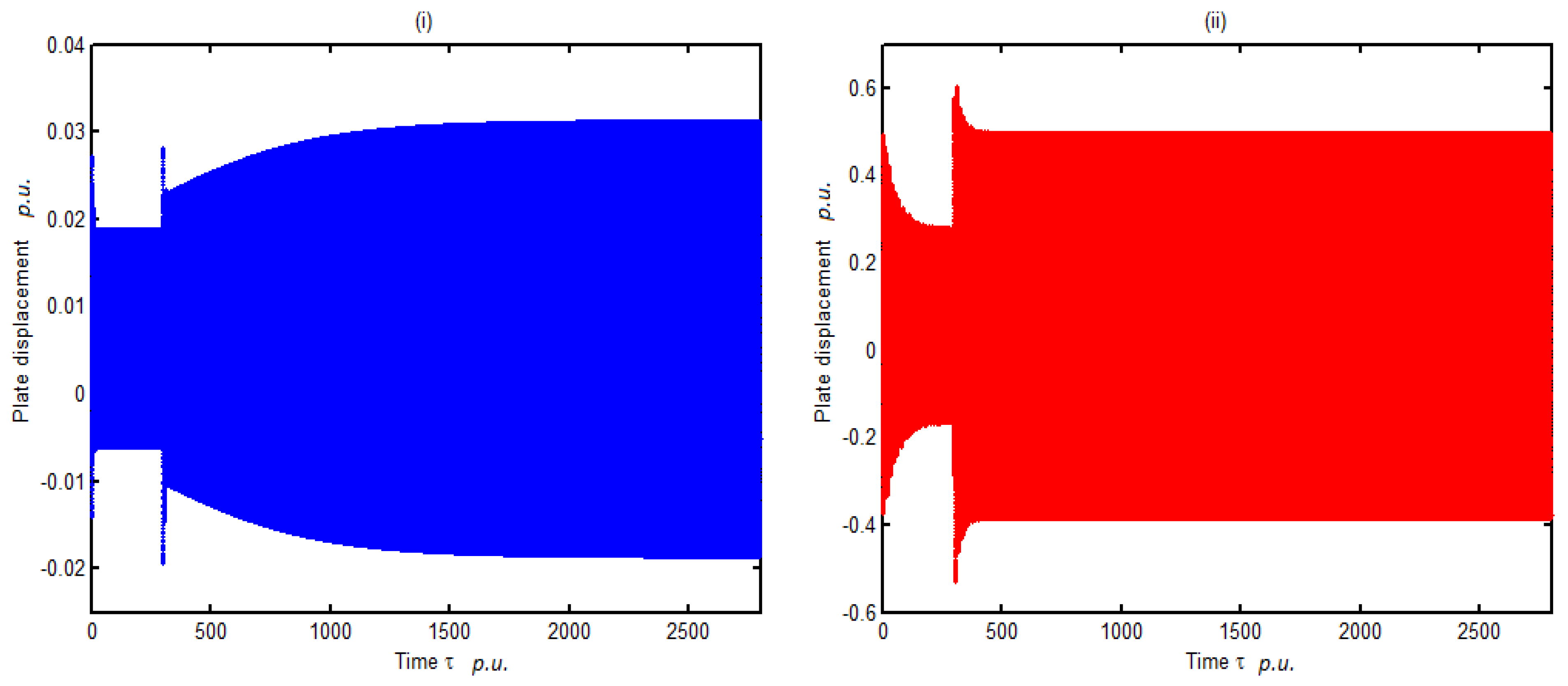
3. Numerical Investigation of Dynamics

This section presents an overview of the numerical solution of the system Equation (5). In order to understand the dynamical response of the system, these equations are integrated numerically with a fourth-order Runge–Kutta scheme. We displayed cases where we have two and three DC electrical machines resting on the rectangular plate, respectively. In each case, the various possibilities that could happen are studied.
For numerical analysis, we considered a rectangular plate with the following physical and mechanical parameters presented in Table 1.

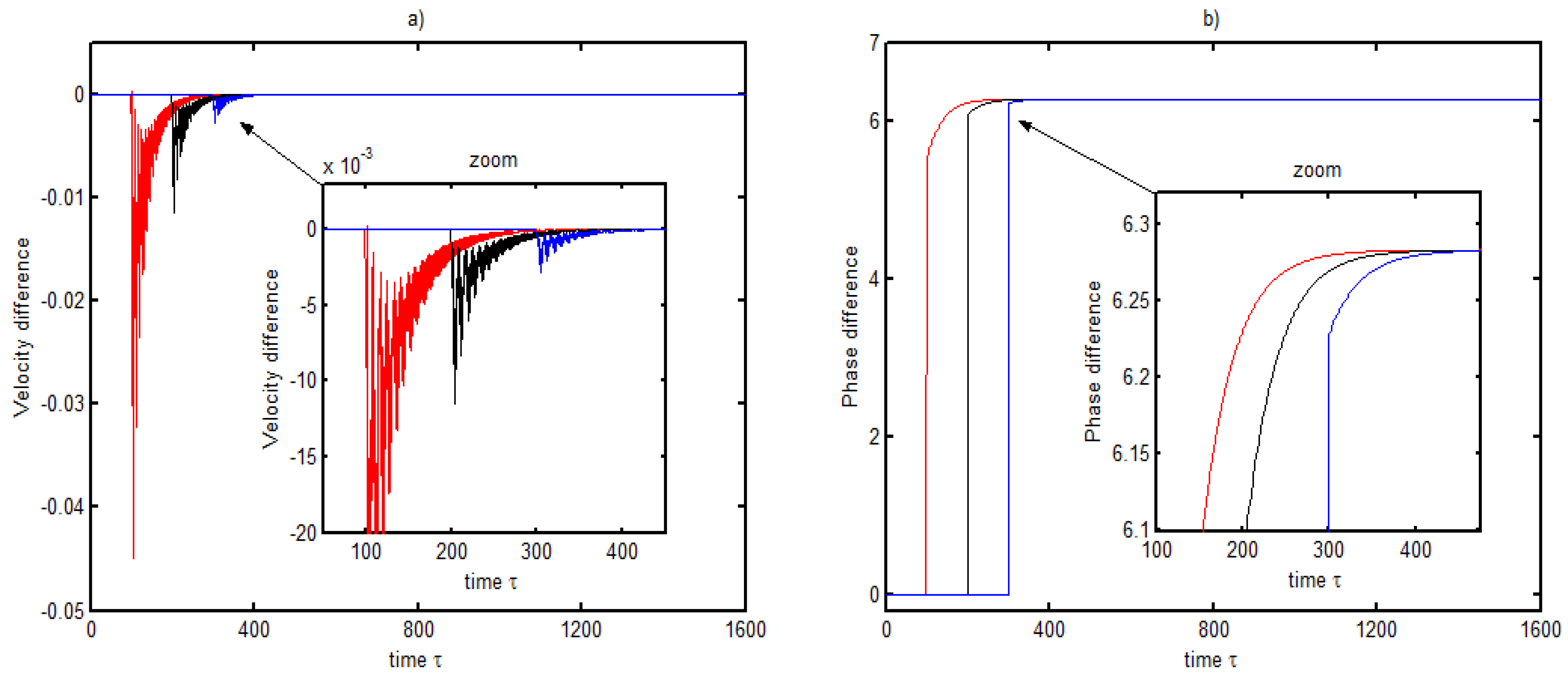
3.1. Dynamic Response of Two DC Electrical Machines

We consider here two DC electrical machines resting and acting on a mechanical structure. By listing physical characteristics of the system, we can enumerate four situations for which the dynamics can be investigated [21].
We first assume the chosen DC electrical machines approximately identical and the physical characteristics leading to coefficients u 1 i = 250 N·m and v 2 i = 1.67 N·m·s/rad (with i = 1 , 2 ) respectively. Here, T 0 = 0.05 s and a = 1.239 m represent the reference values for the time and distance, respectively. The other electrical machines characteristics are given as follows in Table 2.
By exploiting values presented in both tables and taking into account the relation presented in Appendix B, we display the values of numerical parameters present in Equation (5): σ 2 = σ 1 = 4.99 × 10 2 , Γ 2 = Γ 1 = 0.115 , β 2 = β 1 = 0.211 , a 02 = a 01 = 3.21 , b 02 = b 01 = 1.62 .
Figure 3 and Figure 4 show the variation of times for the velocity difference between the DC electrical machines and the phase difference for a precise value of the natural frequency ω 11 of the plate in the first mode in each direction. We note that, for each of them, τ 1 = 0 , but with different values of the normalized delay τ 2 . The study was restricted here to the first mode of vibration in each direction of the plate because it has been proven [30] that it is the place of a high amplitude of vibration in the system. We note that it has been shown [21] that low and high values of the natural frequency of the plate lead to anti-phase and phase synchronization between the electrical machines, respectively.
Figure 3 and Figure 4 were obtained for two values of the natural frequency of the plate, ω 11 = 2.73 and ω 11 = 0.873 , respectively. It was observed in these curves that, when the second DC electrical machine started to function with a delay τ 2 , both DC electrical machines quickly synchronized, the faster for an increased delay. Hence, this lead us to conclude that late switching on of the second electrical machine reduces the time to reach a synchronous state between electrical machines. In particular, when the natural frequency of the plate was low, we could note that, when the phase difference was equal to π , the synchronization state was quickly reached. Thus, we conclude that the physical and mechanical characteristics of the plate (related to natural frequency) have an influence on the time to reach the synchronization state between the electrical machines. The mastery of those parameters benefit in both senses because they contribute to the knowledge of phase differences and impact the fast self-synchronizations between the DC electrical machines.
Figure 3a and Figure 4a represent the velocity difference between the DC electrical machines for three different values of the time delay with values for the main frequency of the structures ω 11 = 2.73 and ω 11 = 0.873 , respectively. There, we can observe that this velocity difference oscillates around zero; meaning that the DC electrical machines are in a synchronization state. However, in Figure 3b and Figure 4b, we show the phase difference between DC electrical machines already synchronized with values 2 π and π , respectively. The zooms presented aim to better appreciate the synchronization phenomenon (Figure 4b) and demonstrate the effect of the time delay on the time to reach a synchronous state (Figure 3a,b and Figure 4b).
However, from Figure 5, we note that, whatever the value of the starting delay imposed to the second DC electrical machine, it doesn’t affect the plate amplitude of vibration in the case of the high natural frequency of the plate. Nevertheless, we denote the presence of a high amplitude of plate vibration when the phase difference φ 2 φ 1 = 2 π is compared to the case of an anti-phase ( φ 2 φ 1 = π obtained with low value of the natural frequency) synchronization between the sources, which is in accordance with previous results [21].

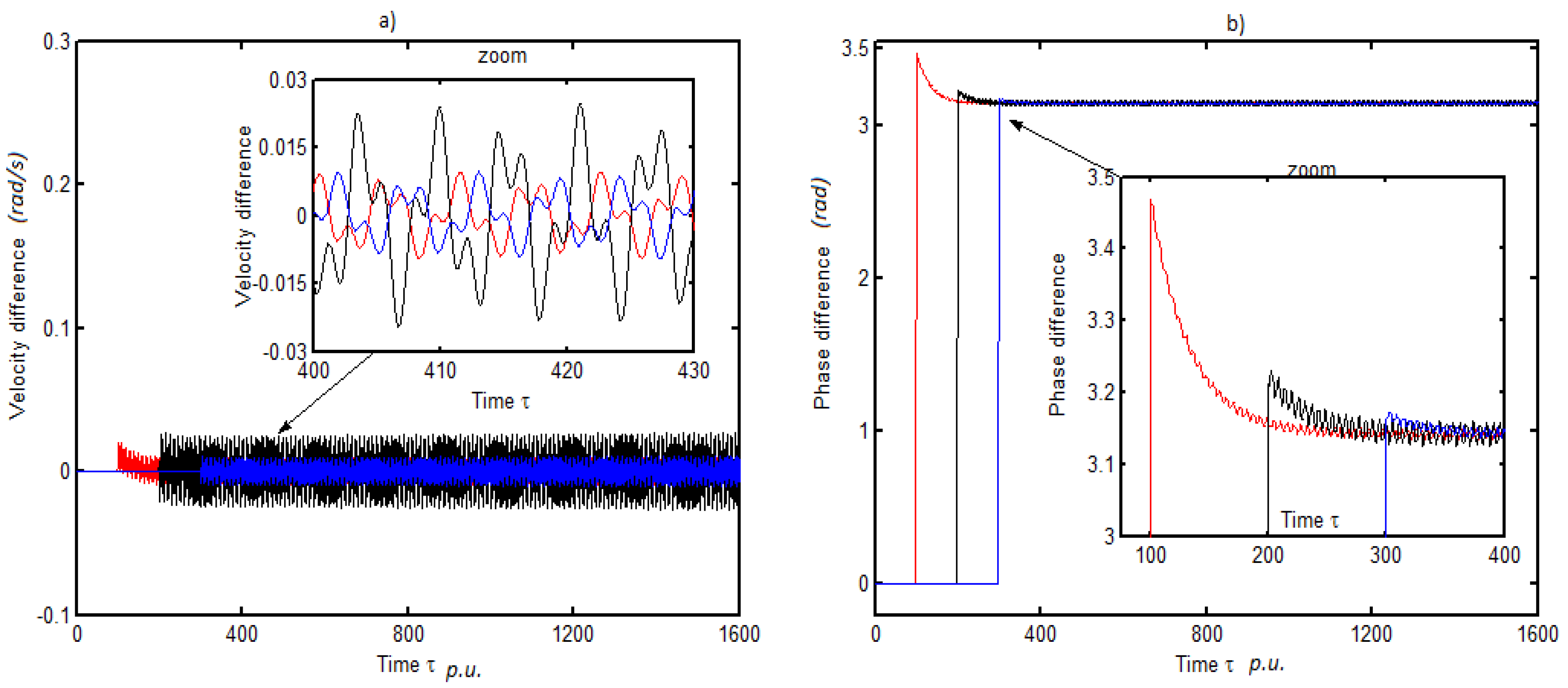
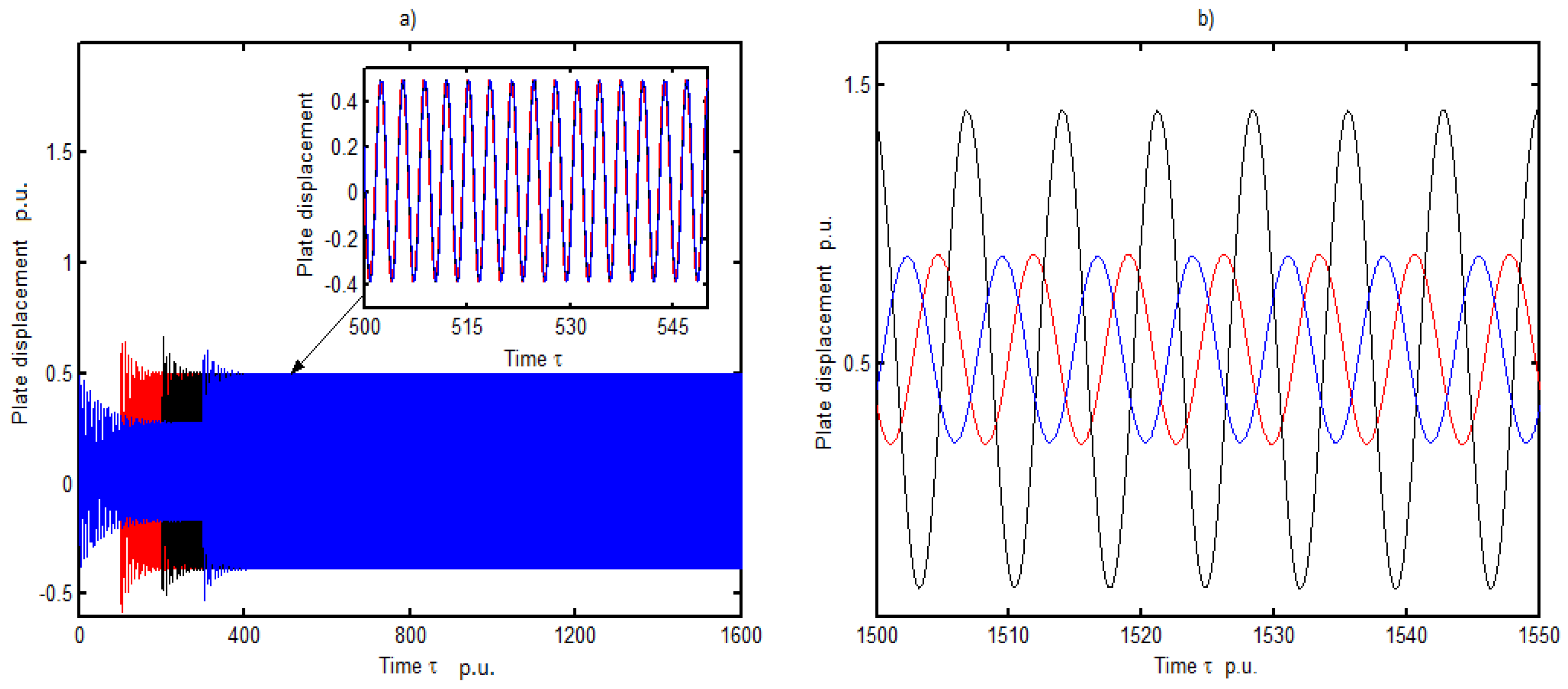
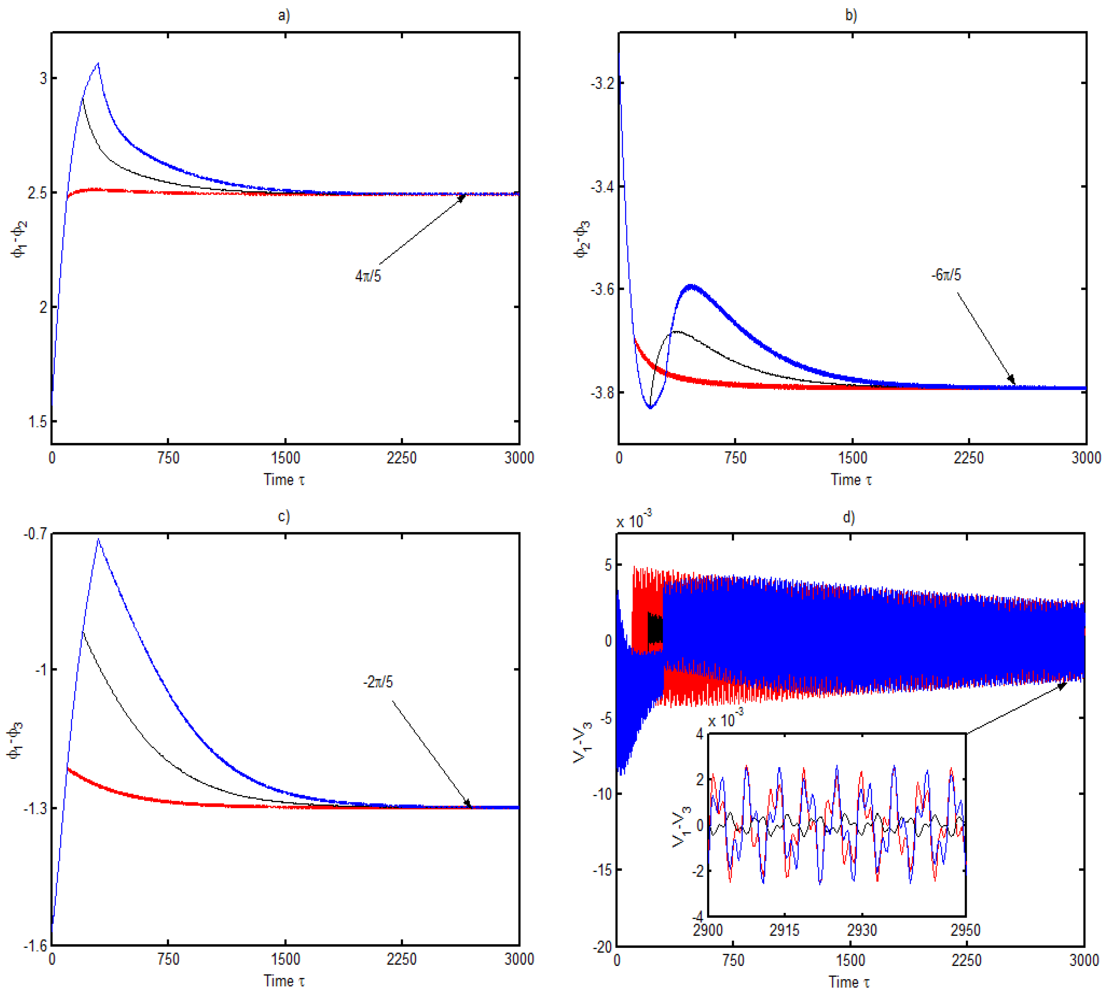
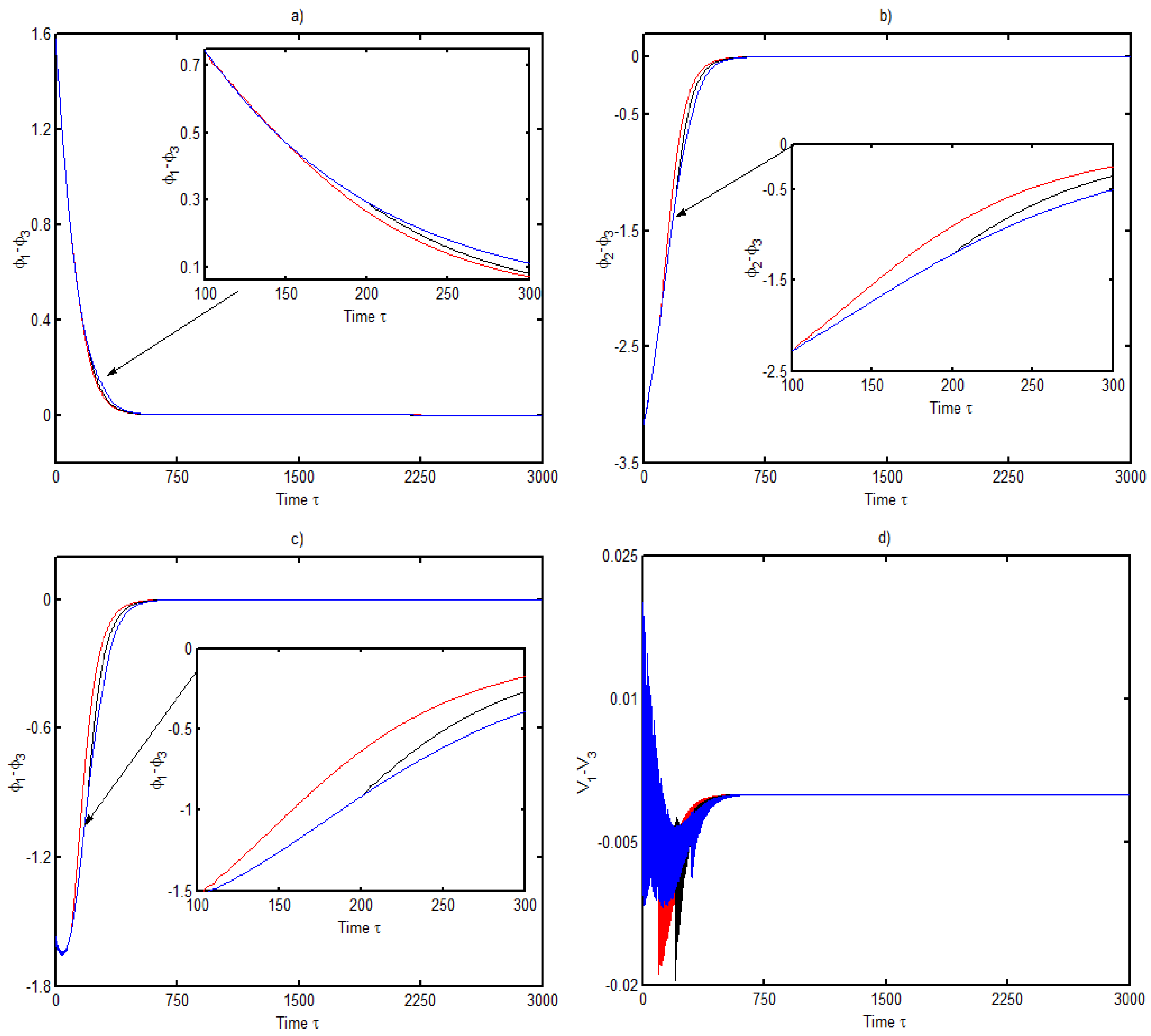
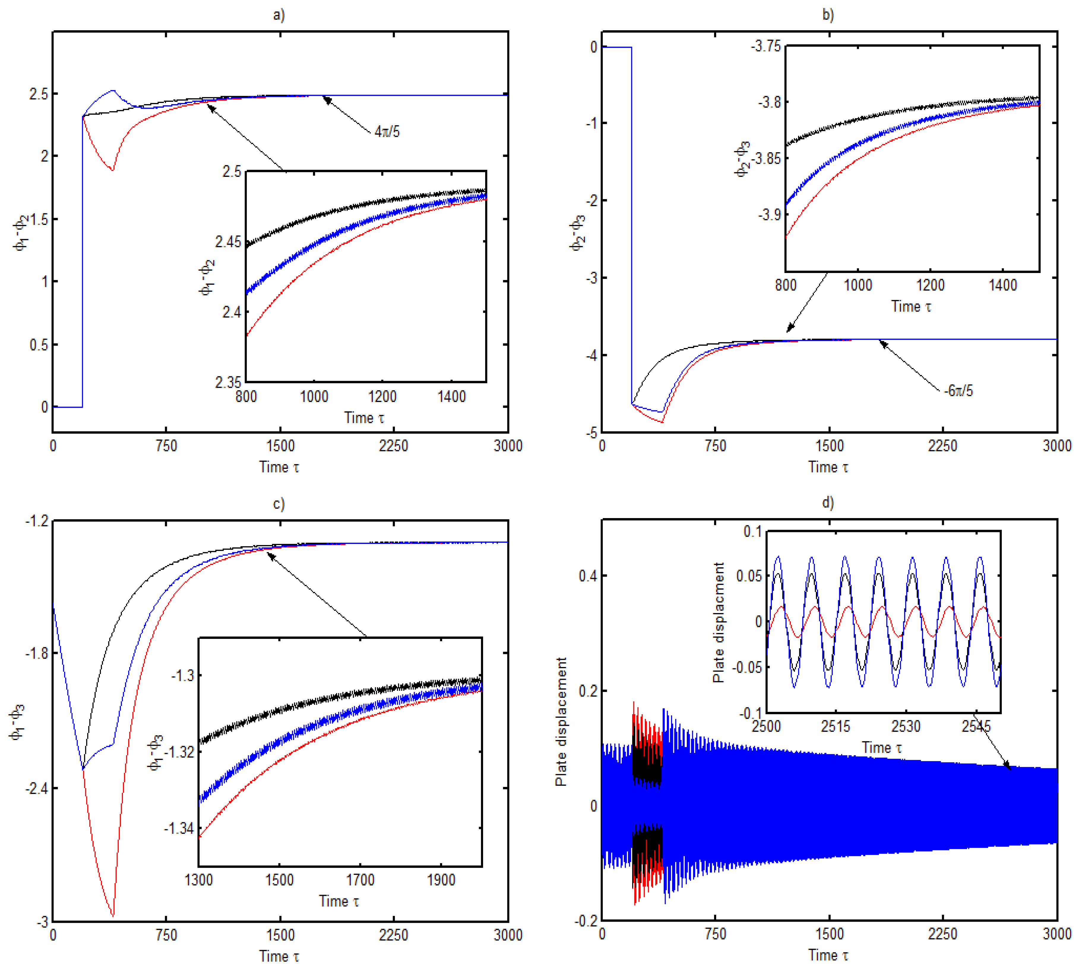
3.2. Dynamic Response of Three DC Electrical Machines

Here, we faced a situation where the first and third electrical machines were symmetrical compared to the second machine placed between them. This inevitably affected the external forces induced by electrical machines to the plate represented in the ODEs because coefficients α i were not more identical. However, the starting delay imposed in the DC electrical machines can be introduced in different ways. Thus, we considered three different situations:
  • The first and the second electrical machines start at the same time τ 1 = τ 2 = 0 and the third starts later at τ 3 0 ,
  • The first and the third electrical machine start at the same time τ 1 = τ 3 = 0 and the second starts later at τ 2 0 ,
  • The first electrical machine starts at τ 1 = 0 and the other two start later at different time τ 2 τ 3 .
When we consider three DC electrical machines mounted on a mechanical structure, we can take into account physical characteristics of the system. Thus, we could enumerate six various situations, for which the dynamics can be studied [31]. Thus, in order to show the effect of the starting delay of the electrical machines on the time required for synchronization, we focused on the case where the DC electrical machines were synchronized (identical electrical machine characteristics and same voltage supply). We mention once more that numerical solutions were provided for the fundamental mode in each direction of the plate and electrical machines rotated in the same direction.
Figure 6 and Figure 7 show the phase difference between the electrical machines in the first case mentioned above, corresponding respectively to ω 11 = 0.873 and ω 11 = 2.83 . We note from these figures that, for ω 11 = 2.83 (Figure 7), the observations made regarding the time to achieve synchronization when we had two DC electrical machines were the same. However, with ω 11 = 0.873 (Figure 7), the starting time of the third electrical machine affected the time required to achieve synchronization of the three DC electrical machines. Thus, from the start of the third DC electrical machine, the three DC electrical machines caused synchronization sooner. This can be explained by the fact that the third DC started when the two others were already synchronized. One can conclude that the natural frequency of the plate (by its physical and mechanical characteristics) contributes efficiently to the rapid self-synchronization between the DC electrical machines. Moreover, we can note that energy transfer was quickly realized between the sources for a high value of the natural frequency of the plate.
In the second case mentioned above, the DC electrical machine placed between the first and the third started with a delay. As shown, the time delay caused late self-synchronization between the DC electrical machines for a low value of the natural frequency, thus we restricted our study to this case.
From Figure 8, obtained with a natural frequency of the plate ω 11 = 0.873 , it is observed that the three DC electrical machines entered in a synchronization state at the same time regardless of the delay imposed on the second DC electrical machine. Comparing Figure 6a–c to Figure 8a–c, we note that, apart from the influence of the delay already observed, the position occupied by the electrical machine which started with a delay could also influence the synchronization time of the three electrical machines. For ω 11 = 2.73 , all the DC electrical machines were in phase synchronization, and the previous observations were also made.
In order to confirm incidence of the area occupied by the DC electrical machines on the plate amplitude when they were started with a delay, we present in Figure 9 the phase difference between the electrical machines and the plate vibration amplitudes. These figures were obtained in the case where τ 1 = 0 , τ 2 τ 3 . It can be scene from these curves that by allowing the second DC electrical machine to start before the third leads to obtaining an earlier synchronization state between the electrical machines (curve in red). However, when the second and third electrical machines started at the same moment, we obtained a later synchronous state of the DC electrical machines (curve in black). While seeking to understand what happens to the plate amplitude of vibrations, we observed that earlier synchronization appearing between electrical machines lead to low values of the amplitude vibration in the mechanical structure. Furthermore, we note that, when the second electrical machine started later than the third, there was a high amplitude of vibration in the plate. This can be explained by the position of the second electrical machine and the fact that it transfers its energy with the two others when they are already in a synchronous state.
As known, in civil and mechanical engineering, we are usually faced with a situation in which one or several rotating machines could rest on a mechanical structure. This result could be useful for engineers in the manufacturing process and also the stability of the whole system. Beyond this fact, when faced with low or high amplitude of vibration in a mechanical system, it is also crucial to seek for stability of the whole studied system.

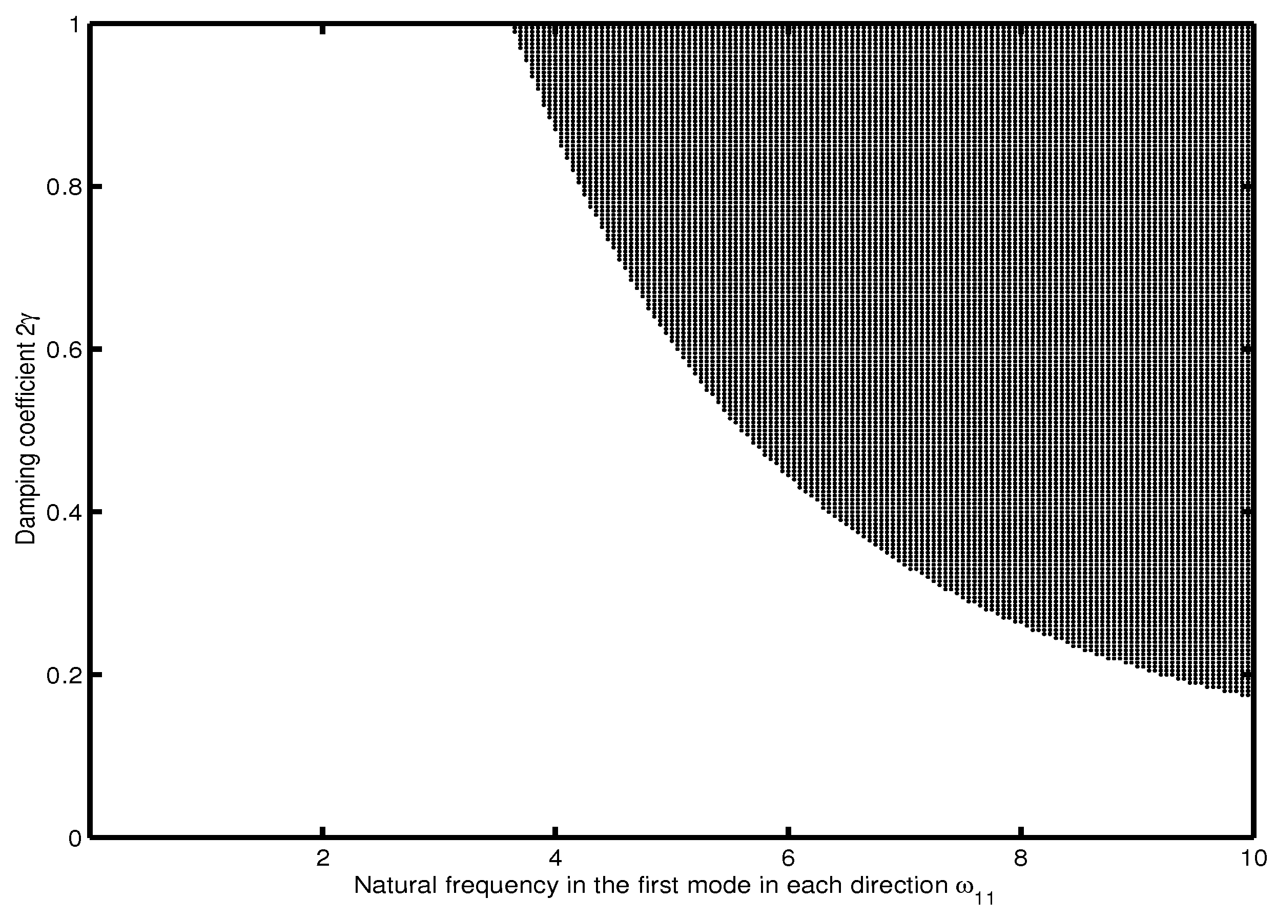
4. Stability Analysis of the System

The theory of dynamical systems is one of the most commonly used keys to solve and understand modern problems occurring in physics, chemistry, biology, and other natural sciences. However, a large variety of mechanical systems composed of a pendulum [32,33,34] or of several coupled pendula [35,36] commonly offer a synchronous dynamics. These dynamics might benefit the structure connected to those pendula in terms of reducing the amplitude of vibration.
Beyond the synchronization state appearing between the DC electrical machines mounted on a rectangular plate, it is primordial to focus on the stability of the synchronized system in order to avoid disasters as much as possible. A such study was done in the past for a rectangular plate supporting a non-ideal source with an electromechanical control [30]. In addition, there are several papers devoted to stability or multistability of rotors or pendula supported by structures or vibrating systems, where the relevance the study is not more to demonstrate [37,38,39]. However, Zhang et al. [40] derived the stability criterion of synchronous states and automatically satisfied the generalized Lyapunov criterion and the Routh–Hurwitz criterion. Later, the stability analysis of the wheel/rail contact dynamics in a curve was performed by using an equivalent point contact model combined with wheel and rail modal bases [41].
In this section, we investigate the stability of the rectangular plate carrying two DC electrical machines, which can enter into phase and opposite synchronization. Therefore, to achieve the goal, we extracted the Jacobian matrix related to the dynamics in Equation (5). Then, they were rewritten as presented in Appendix A with i = 1 , 2 .
Assuming that Y ˙ 11 = f 1 ( Y 11 , Z , φ 1 , V 1 , φ 2 , V 2 ) , Z ˙ = f 2 ( Y 11 , Z , φ 1 , V 1 , φ 2 , V 2 ) , φ 1 ˙ = f 3 ( Y 11 , Z , φ 1 , V 1 , φ 2 , V 2 ) , V 1 ˙ = f 4 ( Y 11 , Z , φ 1 , V 1 , φ 2 , V 2 ) , φ 1 ˙ = f 5 ( Y 11 , Z , φ 1 , V 1 , φ 2 , V 2 ) , V 2 ˙ = f 6 ( Y 11 , Z , φ 1 , V 1 , φ 2 , V 2 ) , we derived the fixed point of the system by solving all the functions f i equal to zero (with i = 1 , . . . , 6 ).
Thus, we obtained ( Y 110 , Z 0 , φ 10 , V 10 , φ 20 , V 20 ) = ( Γ 1 + Γ 2 2 , 0 , 2 ( 1 + a 01 Γ 1 ) , 0 , 2 ( 1 + a 02 Γ 2 ) , 0 ) with the following conditions (where i = 1 , 2 ):
1 i α i σ i c o s 2 φ i 0 , 1 a 0 i Γ i 1 .
The Jacobian matrix obtained around the previous fixed point was derived by evaluating the derivative of the functions f i , with respect to all general coordinates Y 11 , Z , φ 1 , V 1 , φ 2 , V 2 . The polynomial characteristic equation resulting from this matrix is given as follows:
P ( s ) = s 6 + a 1 s 5 + a 2 s 4 + a 3 s 3 + a 4 s 2 + a 5 s + a 6 ,
According to the Routh–Hurwitz criterion [42], the system is stable if the following conditions are satisfied:
a i > 0 , i = 1 , . . . , 6 ,
a 1 a 2 > a 3 ,
a 1 a 2 a 3 > a 4 a 1 2 + a 3 2 ,
a 1 a 2 a 3 a 4 + 2 a 1 a 4 a 5 + a 2 a 3 a 5 > a 1 a 2 2 a 5 + a 1 2 a 4 2 + a 3 2 a 4 + a 5 2 ,
a 1 a 2 a 3 a 4 a 5 + 2 a 2 a 5 a 6 a 1 2 + a 4 a 1 2 a 3 a 6 + 2 a 1 a 4 a 5 2 + a 3 3 a 6 + a 3 a 2 a 5 2 > a 1 a 2 a 3 2 a 6 + a 1 a 2 2 a 5 2 + a 1 2 a 4 2 a 5 + a 6 2 a 1 3 + 3 a 1 a 6 a 3 a 5 + a 3 2 a 4 a 5 + a 5 3 .
The exploitation of these previous conditions leads to obtain the stability chart displayed in Figure 10, where we display the damping coefficient of the system 2 γ as a function of the natural frequency of the plate in the first mode in each direction ω 11 .
There, we observed the presence of two regions. Thus, the whole system was stable around the obtained fixed point in the dark region with points, because it was the place where all the previous conditions were well respected. The white region represents the place of instability in the system. Note that the present stability chart was in accordance with the numerical values used in this paper. To confirm results obtained with the stability chart, we display in Figure 11, in view of their comparison, the plate displacement for two couples of values ( ω 11 ; 2 γ ) in each domain.
Thus, we can observe that, in the instability domain (Figure 11ii), plate amplitude of vibrations are more than 10 times that in the stability domain.
The analysis of this result lead us to conclude that for low values of the natural frequency of the plate, even with strong damping, the system is unstable. While with high value of the natural frequency of the plate, the system is stable even with low damping. This could be confirmed by plotting, in Figure 12, the bifurcation diagram of the system around the obtained fixed point. One can observe that, for high values of the natural frequency of the plate, in the first mode in each direction, the system is more stable. This is in accordance with the domain in black, shown in Figure 10, which is more important, but it increases the natural frequency of the plate. We also observe the predominance of high amplitude for small values of the natural frequency, which is confirmed in the white region of the stability chart.
Hence, the physical and mechanical parameters of the plate (density, young modulus, thickness, length, width), which are strongly related to the natural frequency of the plate, should be well chosen by the manipulator in order to avoid instability in the system. In addition, the environment where the system is placed and other factors influencing the damping of the system should be well chosen to avoid instability.

5. Conclusions

This paper has presented the effect of time delay input imposed on one or two DC electrical machines fixed on a rectangular plate on their synchronization. We investigate the dynamics modal equations of a rectangular plate carrying two or three DC electrical machines through numerical simulation. It it shown that, in the case of two DC electrical machines, the time delay input of the second electrical machine considerably affects the time when the electrical machines are synchronized, since self-synchronization happens earlier. Moreover, we observe that the physical and mechanical characteristics of the plate (related to natural frequency) have an influence on the time to reach the synchronization state between the electrical machines. In the case of three DC electrical machines, the previous observation concerning the time delay input of the second electrical machine was done, and it is observed that, when the natural frequency of the structure increased, the contrary observation was made.
Thus, the mechanical characteristics of the plate, such as the Young’s modulus and the physical parameters, such as density and dimensions, have an influence on the time to reach the synchronous state between DC electrical machines. This result confirms previous findings on the self-synchronization between DC electrical machines [21].
Despite the fact that we observe the influence of the position occupied by electrical machines on the synchronization time of three rotating machines, the time delay imposed on one or two electrical machines also affects the amplitude of the rectangular plate. The analytical method used included a stability analysis of the system when the two DC electrical machines were synchronized. In this sense, a fixed point was obtained with some conditions, and the stability conditions of the system were also presented. It follows that, with respected conditions, the system is always stable with simultaneous high values of the natural frequency of the plate and low damping.
The relevance of this paper comes from the effect of the delayed start of DC electrical machines, leading to an earlier or later synchronization state and its influence on the plate’s vibration amplitude. This fast and late synchronization occurrence is explained by the energy transfer appearing between unbalanced electrical machines. Stability analysis conducted allows us to determine with conditions a fixed point and provides a domain of values ( 2 γ ; ω ) , where we can get a stability state of the system for low and high amplitude of the plate’s vibration.

Author Contributions

Conceptualization, A.A.N.D., S.M. and B.R.N.N.; methodology, A.A.N.D., S.M. and B.R.N.N.; software, A.A.N.D., S.M. and B.R.N.N.; validation, A.A.N.D., S.M. and B.R.N.N.; formal analysis, A.A.N.D., S.M. and B.R.N.N.; investigation, A.A.N.D., S.M. and B.R.N.N.; writing—original draft preparation, A.A.N.D., S.M. and B.R.N.N.; writing—review and editing, A.A.N.D., S.M. and B.R.N.N.; visualization, A.A.N.D., S.M. and B.R.N.N. All authors contributed equitably. All authors have read and agreed to the published version of the manuscript.

Funding

This research received no external funding.

Acknowledgments

The first author is grateful to the German Academic Exchange Service (DAAD) for the support during the research visit stay at the Technical University of Munich.

Conflicts of Interest

The authors declare no conflict of interest in preparing this article.

Appendix A

The DC electrical machines are modelled taking into account electrical features, such as the armature winding resistance R and the inductance L. Thus U, K m , and K e represent the applied voltage, the mechanical and electrical constants relative to the torque T, and the back-EMF effect of each electrical machine, respectively.
L K m T ˙ + R K m T + K e φ ˙ = U .
The dimensionless variables and other constants are given by:
a 0 i = T 0 2 u 1 i ( J i + m i r i 2 ) ; b 0 i = T 0 v 2 i ( J i + m i r i 2 ) ; 2 γ = λ T 0 ρ h + M t a b + M i ;         T i ( φ ˙ ) = a 0 i b 0 i φ ˙ ; Γ i = m i g T 0 2 r i 2 ( J i + m i r i 2 ) ; ω k , l 2 ( τ ) = E h 3 T 0 2 π 4 12 1 ν 2 ρ h + M t a b + M i k a 2 + l b 2 2 ;         σ i , k l = m i r i a k l π 2 ( J i + m i r i 2 ) ( 1 ( 1 ) k ) ( 1 ( 1 ) l ) ; α i ( τ τ i ) = 4 m i r i H ( τ τ i ) a π 2 χ i ψ i ρ h + M t a b + M i [ cos ( k π a x 1 i ) cos ( k π a x 2 i ) ] [ cos ( l π b y 1 i ) cos ( l π b y 2 i ) ] ; β i ( τ τ i ) = 4 M i g T 0 2 H ( τ τ i ) a 2 b π 2 χ i ψ i ρ h + M t a b + M i [ cos ( k π a x 1 i ) cos ( k π a x 2 i ) ] [ cos ( l π b y 1 i ) cos ( l π b y 2 i ) ] ;
where M t = i m i , T 0 is the reference time, H is the heaviside function, and
χ i = x 2 i x 1 i , ψ i = y 2 i y 1 i .

Appendix B

The algebraic equations of the system are rewritten as follows for each general coordinate:
Y ˙ 11 = Z , ( a ) Z ˙ = 2 γ Z ω 2 Y 11 + i α i φ i ˙ 2 s i n φ i α i Γ i c o s 2 φ i α i ( a 0 i b 0 i φ i ˙ ) c o s φ i + β i 1 i α i σ i c o s 2 φ i , ( b ) φ 1 ˙ = V 1 , ( c ) V ˙ 1 = a 01 b 01 V 1 + Γ 1 c o s φ 1 2 γ Z ω 2 Y 11 + i α i φ i ˙ 2 s i n φ i α i Γ i c o s 2 φ i α i ( a 0 i b 0 i φ i ˙ ) c o s φ i + β i 1 i α i σ i c o s 2 φ i σ 1 c o s φ 1 , ( d ) φ 2 ˙ = V 2 , ( e ) V ˙ 2 = a 02 b 02 V 2 + Γ 2 c o s φ 2 2 γ Z ω 2 Y 11 + i α i φ i ˙ 2 s i n φ i α i Γ i c o s 2 φ i α i ( a 0 i b 0 i φ i ˙ ) c o s φ i + β i 1 i α i σ i c o s 2 φ i σ 2 c o s φ 2 , ( f )
The Jacobian matrix obtained from the precedent algebraic equations is given by:
J = 0 1 0 0 0 0 A B C D E F 0 0 0 1 0 0 G H I K L M 0 0 0 0 0 1 N P Q R S T .
The elements of the matrix are presented as follows:
A = ω 2 Δ B = 2 γ Δ C = α 1 a 01 Δ 1 ( a 01 Γ 1 ) 2 D = α 1 a 01 b 01 Δ Γ 1 E = α 2 a 02 Δ 1 ( a 02 Γ 2 ) 2 F = α 2 a 02 b 02 Δ Γ 2 G = σ 1 a 02 ω 2 Δ Γ 1 H = λ σ 1 a 01 Δ Γ 1 I = ( Γ 1 + α 1 σ 1 a 01 2 Δ Γ 1 ) 1 ( a 01 Γ 1 ) 2 K = b 1 α 1 σ 1 b 1 a 01 2 Δ Γ 1 2 L = α 1 σ 1 a 01 2 Δ Γ 1 1 ( a 01 Γ 1 ) 2 M = a 01 a 02 α 2 σ 1 b 02 Δ Γ 1 Γ 2 N = σ 2 a 02 ω 2 Δ Γ 2 P = σ 2 a 02 λ Δ Γ 2 Q = α 1 σ 2 a 01 a 02 Δ Γ 2 1 ( a 01 Γ 1 ) 2 R = σ 2 a 01 a 02 α 1 b 01 Δ Γ 1 Γ 2 S = ( Γ 2 + σ 2 α 2 a 02 2 Δ Γ 2 ) 1 ( a 02 Γ 2 ) 2 T = ( b 02 + α 2 σ 2 b 02 a 02 2 Δ Γ 2 2 )
where Δ = 1 ( α 1 σ 1 a 01 2 Γ 1 + α 2 σ 2 a 02 2 Γ 2 ) .
The coefficients of the characteristics polynomial equation are:
a 1 = T K B , a 2 = P F R M S + T K T B I H D + K B A , a 3 = N F P D M P E Q M R H F R L + P F K + R M B + S K + S B + I T + T H D + T A G D H C + I B + K A , a 4 = G C + I P F N E Q L N D M P C M P D L Q H F R G F R H E + I A + S A + N F K + P E K + Q M B + R L B + I S + R M A + S H D S K B + T G D + T H C I T B T K A , a 5 = N C M N D L P C L Q G F Q H E R G E + N E K + Q L B I T A + I N F + Q M A + R L A + T G C I S B + S G D + S H C + I P E S K A , a 6 = N C L Q G E + I N E + Q L A + S G C I S A .

References

  1. Chen, J.; Hu, W.-H.; Li, Q.-S. Nonlinear dynamics of a foldable multibeam structure with one to two internal resonances. Int. J. Mech. Sci. 2019, 150, 369–378. [Google Scholar] [CrossRef]
  2. Kecik, K.; Mitura, A. Energy recovery from a pendulum tuned mass damper with two independent harvesting sources. Int. J. Mech. Sci. 2020, 174, 105568. [Google Scholar] [CrossRef]
  3. Fan, C.-C.; Pan, M.-C. Active elimination of oil and dry whips in a rotating machine with an electromagnetic actuator. Int. J. Mech. Sci. 2011, 53, 126–134. [Google Scholar] [CrossRef]
  4. Wang, G.; Li, M.; Zhou, J. Modeling soft machines driven by buckling actuators. Int. J. Mech. Sci. 2019, 157, 662–667. [Google Scholar] [CrossRef]
  5. Nbendjo, B.R.N. Amplitude control on hinged-hinged beam using piezoelectric absorber: Analytical and numerical explanation. Int. J. Non-Linear Mech. 2009, 44, 704–708. [Google Scholar] [CrossRef]
  6. Tabejieu, L.M.A.; Nbendjo, B.R.N.; Dorka, U. Identification of horseshoes chaos in a cable-stayed bridge subjected to randomly moving loads. Int. J. Non-Linear Mech. 2016, 85, 62–69. [Google Scholar] [CrossRef]
  7. Pirmoradian, M.; Torkan, E.; Karimpour, H. Parametric resonance analysis of rectangular plates subjected to moving inertial loads via IHB method. Int. J. Mech. Sci. 2018, 142, 191–215. [Google Scholar] [CrossRef]
  8. Alwis, W.A.M.; Grundy, P. On the carrying capacity of rectangular plates under moving loads. Int. J. Mech. Sci. 1985, 27, 187–197. [Google Scholar] [CrossRef]
  9. Debbarma, R.; Chakraborty, S.; Ghosh, S.K. Optimum design of tuned liquid column dampers under stochastic earthquake load considering uncertain bounded system parameters. Int. J. Mech. Sci. 2010, 52, 1385–1393. [Google Scholar] [CrossRef]
  10. Balthazar, J.M.; Mook, D.T.; Weber, H.I.; Fenili, A.; Belato, D.; Felix, J.L.P. An Overview on Non-Ideal Vibrations. Meccanica 2003, 30, 613–621. [Google Scholar] [CrossRef]
  11. Nayfeh, A.H.; Mook, D.T. Nonlinear Oscillations; Wiley: New York, NY, USA, 2008. [Google Scholar]
  12. Balthazar, J.M.; Felix, J.L.P.; Brasil, R.M.L.R.F. On nonlinear dynamics of a particular portal frame foundation model, excited by a non-ideal motor. Mat. Sci. For. 2003, 440, 371–378. [Google Scholar] [CrossRef]
  13. Feulefack, S.E.; Djanan, A.A.N.; Nbendjo, B.R.N. Vibration absorption of a rectangular plate supporting a DC motor with a TLCD. Nonlinear Dyn. 2021, 105, 1357–1372. [Google Scholar]
  14. Cveticanin, L.; Zukovic, M.; Cveticanin, D. Two degree-of-freedom oscillator coupled to a non-ideal source. Int. J. Non-Linear Mech. 2017, 94, 125–133. [Google Scholar] [CrossRef]
  15. Djanan, A.A.N.; Nbendjo, B.R.N.; Woafo, P. Control of vibration on a hinged-hinged beam under a non-ideal excitation using RLC circuit with variable capacitance. Nonlinear Dyn. 2011, 63, 477–489. [Google Scholar]
  16. Balthazar, J.M.; Felix, J.L.P.; Brasil, R.M.L.R.F. Short comments on self-synchronization of two non-ideal sources supported by a flexible portal-frame strucure. J. Vib. Control 2004, 10, 1739–1748. [Google Scholar] [CrossRef]
  17. Balthazar, J.M.; Felix, J.L.P.; Brasil, R.M.L.R.F. Some comments on the numerical simulation of self-synchronization of four non-ideal exciters. Appl. Math. Comput. 2005, 164, 615–625. [Google Scholar] [CrossRef]
  18. Czolczynski, K.; Perlikowski, P.; Stefanski, A.; Kapitaniak, T. Synchronization of pendula rotating in different directions. Commun. Nonlinear Sci. Numer. Simul. 2012, 17, 3658–3672. [Google Scholar] [CrossRef]
  19. Czolczynski, K.; Perlikowski, P.; Stefanski, A.; Kapitaniak, T. Synchronization of slowly rotating pendulums. Int. J. Bif. Chaos 2012, 22, 1250128. [Google Scholar] [CrossRef]
  20. Kapitaniak, M.; Czolczynski, K.; Perlikowski, P.; Stefanski, A.; Kapitaniak, T. Synchronization of clocks. Phys. Rep. 2012, 517, 1–69. [Google Scholar] [CrossRef] [Green Version]
  21. Djanan, A.A.N.; Nbendjo, B.R.N.; Woafo, P. Self-synchronization of two motors on a rectangular plate and reduction of vibration. J. Vib. Control 2015, 21, 2114–2123. [Google Scholar] [CrossRef]
  22. Dimentberg, M.F.; Cobb, E.; Mensching, J. Self-synchronization of transient rotations in multiple shaft systems. J. Vib. Control 2001, 7, 221–232. [Google Scholar] [CrossRef]
  23. Blekhman, I.I. Synchronization in Science and Technology; ASME: New York, NY, USA, 1988. [Google Scholar]
  24. Dimentberg, M.F.; McGovern, L.; Norton, R.L.; Chapdelaine, J.; Harrison, R. Dynamics of an unbalanced shaft interacting with a limited power supply. Nonlinear Dyn. 1997, 13, 171–187. [Google Scholar] [CrossRef]
  25. Cveticanin, L.; Zukovic, M.; Cveticanin, D. Oscillator with variable mass excited with non-ideal source. Nonlinear Dyn. 2018, 92, 673–682. [Google Scholar] [CrossRef]
  26. Litak, G.; Syta, A.; Wasilewski, G.; Kudra, G.; Awrejcewicz, J. Dynamical response of a pendulum driven horizontally by a DC motor with a slider-crank mechanism. Nonlinear Dyn. 2020, 99, 1923–1935. [Google Scholar] [CrossRef]
  27. Djanan, A.A.N.; Nbendjo, B.R.N. Effects of two moving non-ideal sources on the dynamic of a rectangular plate. Nonlinear Dyn. 2018, 92, 645–657. [Google Scholar] [CrossRef]
  28. Kong, X.; Zhou, C.; Wen, B. Composite synchronization of four exciters driven by induction motors in a vibration system. Meccanica 2020, 55, 2107–2133. [Google Scholar] [CrossRef]
  29. Kong, X.; Jiang, J.; Zhou, C.; Xu, Q.; Chen, C. Sommerfeld effect and synchronization analysis in a simply supported beam system excited by two non-ideal induction motors. Nonlinear Dyn. 2020, 100, 2047–2070. [Google Scholar] [CrossRef]
  30. Djanan, A.A.N.; Nbendjo, B.R.N.; Woafo, P. Electromechanical control of vibration on a plate submitted to a non-ideal excitation. Mech. Res. Comm. 2013, 54, 72–82. [Google Scholar] [CrossRef]
  31. Djanan, A.A.N.; Nbendjo, B.R.N.; Woafo, P. Effect of self-synchronization of DC motors on the amplitude of vibration of a rectangular plate. Eur. Phys. J. Spec. Top. 2014, 223, 813–825. [Google Scholar] [CrossRef]
  32. Shaw, J.; Shaw, S.W. Non-linear resonance of an unbalanced rotating shaft with internal damping. J. Sound Vib. 1991, 147, 435–451. [Google Scholar] [CrossRef]
  33. Haddow, A.G.; Shaw, S.W. Centrifugal Pendulum Vibration Absorbers: An Experimental and Theoretical Investigation. Nonlinear Dyn. 2003, 34, 293–307. [Google Scholar] [CrossRef]
  34. Ikeda, T. Nonlinear Responses of Dual-Pendulum Dynamic Absorbers. J. Comp. Nonlinear Dyn. 2011, 6, 011012. [Google Scholar] [CrossRef]
  35. Dudkowski, D.; Czolczynski, K.; Kapitaniak, T. Traveling amplitude death in coupled pendula. Chaos 2019, 29, 083124. [Google Scholar] [CrossRef] [PubMed]
  36. Dudkowski, D.; Czolczynski, K.; Kapitaniak, T. Traveling chimera states for coupled pendula. Nonlinear Dyn. 2019, 95, 1859–1866. [Google Scholar] [CrossRef] [Green Version]
  37. Czolczynski, K.; Marynowski, K. Stability of symmetrical rotor supported in flexibly mounted, self-acting gas journal bearings. Wear 1996, 194, 190–197. [Google Scholar] [CrossRef]
  38. Tan, X.; Chen, G.; He, H.; Chen, W.; Wang, Z.; He, J.; Wang, T. Stability analysis of a rotor system with electromechanically coupled boundary conditions under periodic axial load. Nonlinear Dyn. 2021, 104, 1157–1174. [Google Scholar] [CrossRef]
  39. Shaw, J.; Shaw, S.W. Instabilities and bifurcations in a rotating shaft. J. Sound Vib. 1989, 132, 227–244. [Google Scholar] [CrossRef]
  40. Zhang, X.; Wen, B.; Zhao, C. Synchronization of three non-identical coupled exciters with the same rotating directions in a far-resonant vibrating system. J. Sound Vib. 2013, 332, 2300–2317. [Google Scholar] [CrossRef]
  41. Lai, V.-V.; Brunel, C.O.J.-F.; Dufrnoy, P. The critical effect of rail vertical phase response in railway curve squeal generation. Int. J. Mech. Sci. 2020, 167, 105281. [Google Scholar] [CrossRef]
  42. Hayashi, C. Nonlinear Oscillations in Physical Systems; Princeton University Press: New York, NY, USA, 1964. [Google Scholar]
Figure 1. Illustration in mechanical engineering of a non-ideal vibrating system: (a) Front view of a simplified representation of a compacting machine with its physical model (b).
Mca 27 00020 g001
Figure 2. Rectangular plates of known dimensions (length a, width b, and thickness h), supporting DC electrical machines with unbalanced masses m i at a distance r i from their rotating axis. Plates are simply supported edges capable of moving in x , y , z directions, but only transversal displacement in z direction is considered here. Plates are not connected and are able to move independently. Angular displacement of each electrical machine is denoted by φ i . The space dimensions occupied by each electrical machine on the plate are noted as a i and b i , where i = 1 , 2 , 3 .
Mca 27 00020 g002
Figure 3. Representation of velocity difference (a) and phase difference (b) between the two DC electrical machines as a function of dimensionless time computed with α 1 = α 2 = 0.201 when the main frequency of the structure is ω 11 = 2.73 . The second DC electrical machine starts with different delays: τ 2 = 100 (red); τ 2 = 200 (black); τ 2 = 300 (blue), while the first is already on. The electrical machines are already fixed on the rectangular plate before switching on the first electrical machine and are regularly spaced on it. They rotate in the same direction when they are switched on.
Mca 27 00020 g003
Figure 4. Representation of velocity difference (a) and phase difference (b) between the two DC electrical machines as a function of dimensionless time computed with α 1 = α 2 = 0.201 when the main frequency of the structure is ω 11 = 0.873 . The second DC electrical machine starts with a delay: τ 2 = 100 (red); τ 2 = 200 (black); τ 2 = 300 (blue), while the first electrical machine is already on. The DC electrical machines are already fixed on the rectangular plate before switching on the first electrical machine and are regularly spaced on it. They rotate in the same direction when they are switched on.
Mca 27 00020 g004
Figure 5. Representation of plate amplitude vibration for two values of the main frequency of the plate ω 11 = 2.73 (a) and ω 11 = 0.873 (b) in view of their comparison. The first DC electrical machine is already on when the second starts with a delay: τ 2 = 100 (red); τ 2 = 200 (black); τ 2 = 300 (blue). They are computed when α 1 = α 2 = 0.201 . In addition, electrical machines are already fixed on the rectangular plate before switching on the first electrical machine and are regularly spaced on it. They rotate in the same direction when they are switched on.
Mca 27 00020 g005
Figure 6. Representation of the phase difference (ac) between the three electrical machines and velocity difference between the DC1 and DC3 (d) for a main frequency of the structure of ω 11 = 0.873 . The first and the second DC electrical machines start at the same moment τ 1 = τ 2 = 0 , while the third starts with a delay: τ 3 = 100 (red); τ 3 = 200 (black); τ 3 = 300 (blue). They are computed with α 1 = α 3 = 0.056 and α 2 = 0.088 . In addition, electrical machines are already fixed on the rectangular plate before switching on the first electrical machine and are regularly spaced on it. They rotate in the same direction when they are switched on.
Mca 27 00020 g006
Figure 7. Representation of the phase difference (ac) between the three electrical machines and velocity difference between the DC1 and DC3 (d) for a main frequency of the structure of ω 11 = 2.73 . The first and second DC electrical machines start at the same moment τ 1 = τ 2 = 0 , while the third starts with a delay: τ 3 = 100 (red); τ 3 = 200 (black); τ 3 = 300 (blue). They are computed with α 1 = α 3 = 0.056 and α 2 = 0.088 . In addition, electrical machines are already fixed on the rectangular plate before switching on the first electrical machine and are regularly spaced on it. They rotate in the same direction when they are switched on.
Mca 27 00020 g007
Figure 8. Representation of the phase difference (ac) between the three DC electrical machines and plate amplitude of vibration (d) for a main frequency of the structure of ω 11 = 0.873 . The first and the third DC electrical machines start at the same moment τ 1 = τ 3 = 0 , while the second starts with a delay when τ 2 = 100 (red); τ 2 = 200 (black); τ 2 = 300 (blue). The zoom on plate amplitude of vibration leads to the appreciation of delay effects on amplitude of vibration. They are computed with α 1 = α 3 = 0.056 and α 2 = 0.088 . In addition, electrical machines are already fixed on the rectangular plate before switching on the first electrical machine and are regularly spaced on it. They rotate in the same direction when they are switched on.
Mca 27 00020 g008
Figure 9. Representation of the phase difference (ac) between the three DC electrical machines and plate amplitude of vibration (d) for a main frequency of the structure of ω 11 = 0.873 . Here, the second and third electrical machines start later at different moments, τ 2 = 1 2 τ 3 = 200 (red); τ 2 = τ 3 = 200 (black); τ 2 = 2 τ 3 = 400 (blue), when the first is already on ( τ 1 = 0 ). The zoom on plate amplitude of vibration leads to the appreciation of delay effects on amplitude of vibration. They are computed with α 1 = α 3 = 0.056 and α 2 = 0.088 . In addition, electrical machines are already fixed on the rectangular plate before switching on the first electrical machine and are regularly spaced on it. They rotate in the same direction when they are switched on.
Mca 27 00020 g009
Figure 10. Stability chart of the system around the fixed point ( Y 110 , Z 0 , φ 10 , V 10 , φ 20 , V 20 ) obtained by respecting the Routh–Hurwitz criterion and conditions presented in Equation (7). It shows the region depending on the natural frequency of the rectangular plate and the damping coefficient, where we could obtain stability of the system around the obtained fixed point. It is computed for α 1 = α 2 = 0.201 , when the electrical machines are rotating in the same direction and is regularly spaced on the rectangular plate.
Mca 27 00020 g010
Figure 11. Representation of the plate displacement for two couples of value of the stability chart in view of their comparison. The first value (i) is obtained in the stability zone in black for ( ω 11 = 8.1906 , 2 γ = 0.49 ), while the second one (ii) is plotted in the instability domain for ( ω 11 = 2.7302 , 2 γ = 0.000984870 ).
Mca 27 00020 g011
Figure 12. Bifurcation diagram of the system for 2 γ = 0.000984870 , confirming the stability region obtained for increasing values of the natural frequency of the plate in the first mode in each direction.
Mca 27 00020 g012
Table 1. Physical and mechanical parameters of the rectangular plate studied.
QuantitiesNotationsValuesUnits
Dimensions (length, width, thickness)a × b × h1239 × 619.5 × 5mm3
Density ρ 2700 kg / m 3
Young modulusE6.9 × 10 10 N / m 2
Poisson ratio ν 0.33-
Table 2. Parameters of each DC electrical machine.
QuantitiesNotationsValuesUnits
Unbalanced mass m i 173.4 g
Excentricity r i 14.3 cm
electrical machine mass M i 1740g
Inertia moment J i 0.01 kg·m2
Publisher’s Note: MDPI stays neutral with regard to jurisdictional claims in published maps and institutional affiliations.

