Article

Integrated Finite Strip Computation for Modelling and Frequency Analysis of Hybrid Laminated FRP Structures

by
Hamidreza Naderian
1,2,*,
Moe M. S. Cheung
2,3,
Elena Dragomirescu
4 and
Abdolmajid Mohammadian
4
1
Department of Civil and Mineral Engineering, University of Toronto, 35 St. George Street, Toronto, ON M5S 1A4, Canada
2
Department of Civil and Environmental Engineering, Hong Kong University of Science and Technology, Clear Water Bay, Kowloon, Hong Kong, China
3
Western China Earthquake and Hazards Mitigation Research Centre, Sichuan University, Chengdu 610065, China
4
Department of Civil and Environmental Engineering, University of Ottawa, 161 Louis Pasteur Private, Ottawa, ON K1N 6N5, Canada
*
Author to whom correspondence should be addressed.
Math. Comput. Appl. 2022, 27(3), 47; https://doi.org/10.3390/mca27030047
Submission received: 14 February 2022 / Revised: 21 May 2022 / Accepted: 21 May 2022 / Published: 27 May 2022

Abstract

:
This paper proposes an efficient numerical technique for simulating hybrid fiber-reinforced polymer (FRP) bridge systems. An integrated finite strip method (IFSM) is proposed to evaluate the free vibration performance of cable-stayed FRP bridges. The structural performance of the ultra-long span cable-stayed bridge (ULSCSB) is totally different than steel and concrete bridge structures due to the complexity of the mechanical behavior of the FRP deck. Herein, the anisotropic nature of the FRP laminated deck is considered in the analysis by introducing so-called laminate spline strips in the integrated finite strip solution. The structural interactions between all the components of the bridge can be handled using the proposed method. Column strips and cable strips are introduced and used to model the towers and cables, respectively. In addition, a straightforward scheme for modeling boundary conditions is developed. A case study is presented through which the accuracy and efficiency of the IFSM in modeling such structures, as well as in performing natural frequency analysis of long-span cable-stayed FRP bridges, are evaluated. The finite strip results are verified against the finite element analysis, and a significant enhancement in efficiency in terms of reduction in computational cost is demonstrated with the same level of accuracy.

1. Introduction

The finite strip method (FSM) provides an attractive numerical approach for analyzing bridge structures. Its high accuracy and efficiency due to its semi-analytical nature as well as its rapid convergence of iterations owing to the small bandwidth elastic matrices, along with the simplicity of its input data and simulations, have made FSM outstanding among conventional numerical techniques for bridge analysis [1]. Despite the merits of the FSM in structural analysis [1,2,3,4,5,6], there is currently no comprehensive commercial FSM software available for engineering calculations. In addition, this method is only applicable to structural elements with simple shapes such as plates and shells and folded plate structures. When it comes to a more complicated system, such as a cable-stayed bridge with numerous structural elements attached together in different orientations, the FSM is no longer a powerful tool for the 3D modeling and simulation of a structure. Therefore, until recently, the application of FSM for cable-stated bridges was limited to modeling bridge decks only, while other structural components such as piers, towers, and cables were modeled as special boundary conditions of the deck [7]. Alternatively, a combination of FSM and other numerical solutions such as FEM and the boundary element method (BEM) can model the entire bridge system. However, only an iterative process can provide compatibility and model the interactions between the displacements of the joint knots. This technique is only effective for structures with simple geometric shapes under static or quasi-static forces. In the case of complex systems such as a long-span cable-stayed hybrid fiber-reinforced polymer (FRP) bridge and/or structures under dynamic or aerodynamic excitations, such as non-uniform seismic waves and self-excited wind forces, the iterative process is no longer efficient. When external forces are applied to the bridge, the internal forces are transmitted between structural elements. Particularly, in dynamic phenomena such as earthquakes, the effects of seismic waves are transmitted from the foundation of the bridge to the piers and towers, and then to the deck and cables. Therefore, handling the structural interactions of all elements of a bridge system is a necessary step in performing accurate dynamic analyses and design of bridges. For all these reasons, the application of the FSM in bridge analysis had been close to its technical limits for more than a decade. After a number of years of research on developing and trying different solutions, Cheung et al. [7,8,9] created an innovative integrated framework that is capable of 3D modeling an entire long-span cable-stayed bridge system with the spline finite strip method, where the effects of structural interactions between different segments of the bridge are also handled.
FRP materials have superior structural specifications over traditional steel and concrete materials, such as high strength and stiffness to mass ratios, high resistance to corrosion, and favorable fatigue characteristics. This has encouraged the use of advanced composite materials in long-span cable-stayed bridges. Among the important factors involved in designing, maintaining, and constructing long-span cable-stayed bridges are lengthening the bridge span and lifecycle effectiveness, as well as earthquake and aerodynamic stability. With the rapid development of advanced hybrid fiber-reinforced polymer (FRP) materials for use in the construction of cable-stayed bridges, some of these goals, including increasing the length of main spans of bridges as well as providing better structural conditions of superstructures, can be achieved. Nevertheless, dynamic and aerodynamic instability has become a critical issue because of the significant reduction in the weight of the structure, which makes a bridge more sensitive to the vibration of extreme natural hazards such as earthquakes and typhoons. Similar to other techniques for dynamic analysis of thin-walled structures such as the finite element method and generalized beam theory [10,11,12,13], the finite strip method also has the great potential to handle the dynamic and vibration characteristics of the laminated FRP deck as a thin-walled member. Research shows that the stiffness of advanced composite materials, including FRP, is coupled with the geometry of the structure [14,15]. This indicates the importance of accurate simulation of composite structure geometry, although it is a very expensive computational process.
Despite the great potential for popularizing FRP materials in ultra-long span cable-stayed bridges, conventional design methods are not adequate for hybrid FRP cable-stayed bridges due to the complexity of the failure mechanisms and the anisotropic nature of FRP laminates. In contrast with traditional steel and concrete materials, which are typically modeled as isotropic materials, FRP composites are highly anisotropic depending on the type of fibers, the matrix, and the orientation of each lamina. Taking into account the above features, the structural performance of long-span cable-stayed hybrid FRP bridges, especially regarding their dynamic and aerodynamic characteristics, is totally different from conventional cable-stayed bridges due to their longer spans, lighter weights, and more flexible structural systems. In addition, the highly non-linear material properties coupled with the geometrical complexity make the structural analysis and design of cable-stayed FRP bridges much more challenging.
The first all-composite cable-stayed bridge was the Aberfeldy Footbridge in the UK, where the main structure was a cable-stayed bridge with a glass fiber reinforced polymer (GFRP) deck suspended by Parafil aramid ropes and GFRP towers. Salim et al. [16] carried out research on the analysis and design of FRP composite deck-and-stringer bridges. By using pultruded FRP shapes, Qiao et al. [17] suggested a systematic approach for the analysis of FRP deck bridges. Bridge engineering researchers at the University of California, San Diego, in collaboration with the Federal Highway Administration, built a four-lane traffic way composite cable-stayed bridge with a length of 137.2 m and an A-frame pylon of 57.9 m in height [18]. In spite of the state-of-the-art research on the application of FRP materials in short-span bridges, there is still a lack of research on FRP-based long-span cable-stayed bridges. Almansour and Cheung [19,20,21,22] proposed a comprehensive multi-scale design approach for hybrid FRP bridges at both micro and macro levels and performed a number of case studies which resulted in the development of different types of FRP deck sections for long-span cable-stayed bridges. The studies by Virlogeux showed that a very thin FRP deck section can support static and traffic loads applied to a cable-stayed bridge [23]. Through experimental tests, Burgueno et al. [24] investigated the dynamic characteristics of FRP composite bridges. Cheung and his research group at the Hong Kong University of Science and Technology and Sichuan University carried out extensive analytical and experimental research on micro-scale and macro-scale designs for FRP bridge decks for a number of existing bridges [25,26,27]. Their design process was based on the multi-scale design approach introduced by Cheung and Almansour [21,22], considering FRP laminated material configurations and micro-material properties.
To the best knowledge of the authors, only a few numerical methodologies have been proposed in the literature on ULSCSBs [28,29,30]. In this paper, the integrated finite strip method, as a very accurate and user-friendly technique, is extended for modeling hybrid FRP deck bridges. The laminate spline strip is proposed for modeling anisotropic laminated FRP decks, considering the coupling effects between the flexural and membrane displacements of the FRP deck, while a rapid convergence rate for the numerical results is still guaranteed. Integrating the laminate strips with so-called column strips for modeling towers and piers, cable strips for modeling cables, and transition section elements for modeling the bearings at the intersection joints will provide the opportunity to model the entire hybrid FRP bridge in the IFSM. The structural stiffness and mass property matrices for the whole bridge are obtained in this paper, and a standard eigenvalue analysis is performed to evaluate the free vibration performance. In the following sections, the numerical procedure will be explained. The developed methodology will be examined by performing two case studies, one on an FRP deck slab-girder bridge and one on a long-span cable-stayed hybrid FRP bridge system. The accuracy and efficiency of the proposed models in natural frequency analysis of the selected long-span FRP bridge will be investigated through comparison with the finite element analysis.

2. Methodology

2.1. FRP Deck Modelling

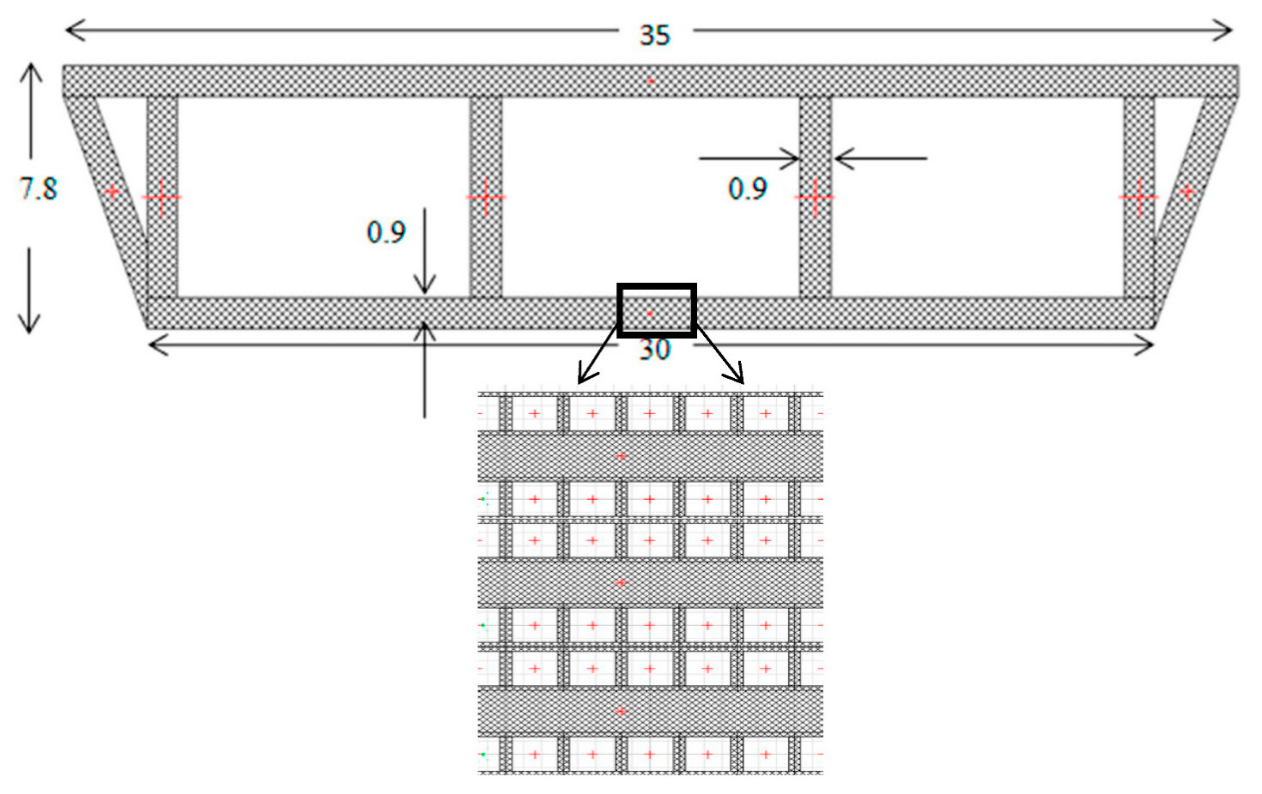
The proposed methodology in this paper for FRP deck modeling is explained in the following. To model a composite FRP deck, a laminated FRP plate can be selected, which is itself a collection of FRP lamina arranged in a specified order. Adjacent lamina may be of the same or different materials, and their fiber orientations with respect to a reference axis may be arbitrary. In Figure 1, a rectangular multi-layer composite flat FRP plate, divided by laminate finite strips, is shown. The classical lamination theory is used in the present study to derive the stiffness matrix of a composite laminated FRP plate in the integrated finite strip method. In the lamination theory, it is assumed that each lamina is in a state of plane stress while the interlaminar stresses are neglected. In addition, a perfect bonding between different laminas is assumed, which means that the laminated FRP plate behaves as a homogenous anisotropic plate.
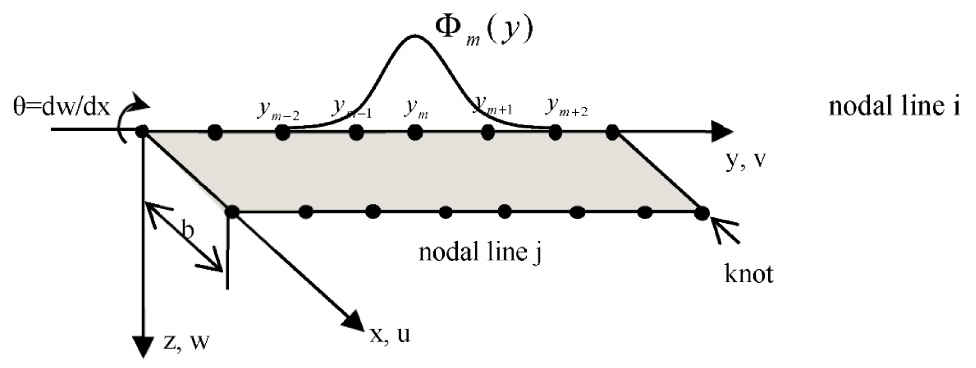
The displacement of a laminate spline strip is obtained by applying unequally spaced B3-spline functions in the longitudinal direction of the strip, and polynomials in the transverse direction. Figure 2 defines the coordinate system, whose origin is assumed to be at the middle surface of the FRP laminated plate. As a result of assuming the plane stress condition for each lamina, transverse shear strains are neglected. The in-plane displacements are linear functions of the z coordinate, and the transverse normal strain is negligible. The displacements of the FRP laminate at a general point u ¯ ,   v ¯ ,   w ¯ can be expressed in terms of:
u ¯ x , y , z = u x , y + z ψ x x , y
v ¯ x , y , z = v x , y + z ψ y x , y
w ¯ x , y , z = w x , y
where ψ x and ψ y are independent rotations, and u, v, and w are displacements at the middle surface of the laminate along the x, y, and z axes, respectively.
The FRP composite deck is discretized into a number of laminate spline strips, as shown in Figure 2, in which both in-plane and out-of-plane degrees of freedom are considered. One can consider four degrees of freedom on each knot of a nodal line of a spline strip: three translational and one rotational. The total potential energy of a flat laminate spline strip is obtained by algebraic summation of the membrane (in-plane) and bending (out-of-plane) deformations. The displacement parameters vector of a laminate spline strip centered at y m is given by:
δ m = u i m , v i m ,   w i m ,   θ i m ,   u j m , v j m ,   w j m ,   θ j m T
In the formulation of the integrated finite strip method, in order to obtain acceptable results, it is better that the locations of the supports and the concentrated load coincide with the knots on the nodal lines. To achieve this goal, unequally spaced B3-spline functions are used in the present study. Moreover, the introduction of unequally spaced interior knots allows obtaining a more accurate response in regions with high stress gradients or at the locations of abrupt geometric changes by spacing the knots more closely. In this case, the spline function centered at y m can be expressed as:
Φ m ( y ) = 0 y < y m 2 A m y y m 2 3 y m 2 y < y m 1 A m y y m 2 3 + C m y y m 1 3 y m 1 y < y m B m y m + 2 y 3 + D m y m + 1 y 3 y m y < y m + 1 B m y m + 2 y 3 y m + 1 y < y m + 2 0 y m + 2 y
in which:
A m = y m + 1 y m 2 y m y m 2 y m 1 y m 2 1 B m = y m + 2 y m 2 y m + 2 y m y m + 2 y m + 1 1 C m = y m + 2 y m 2 y m + 2 y m 1 y m + 1 y m 1 y m y m 1 y m 1 y m 2 1 D m = y m + 2 y m 2 y m + 1 y m 2 y m + 1 y m 1 y m + 1 y m y m + 2 y m + 1 1
The membrane displacement functions u and v and the flexural displacement function w at the middle surface of the laminate can be expressed as the product of transverse polynomials and longitudinal B3-splines as follows:
u =   m = 1 r + 1 N 1 Φ 1 m y u i m + N 2 Φ 5 m y u j m
v =   m = 1 r + 1 N 1 Φ 2 m y v i m + N 2 Φ 6 m y v j m
w =   m = 1 r + 1 N 3 Φ 3 m y w i m + N 4 Φ 4 m y θ i m + N 5 Φ 7 m y w j m + N 6 Φ 8 m y θ j m
or
f = u v w = N 1 N 2 N 1 N 2 N 3 N 4 N 5 N 6 Φ 1 m Φ 2 m Φ 3 m Φ 4 m Φ 5 m Φ 6 m Φ 7 m Φ 8 m { u i m v i m w i m θ i m u j m v j m w j m θ j m }
where r is the total number of longitudinal sections on a nodal line and:
N 1 = 1 X ,   N 2 = X ,   N 3 = 1 3 X 2 + 2 X 3 ,   N 4 = x 1 2 X + X 2 ,     N 5 = 3 X 2 2 X 3 ,     N 6 = x X 2 X ,
in which X = x / b and Φ 1 m to Φ 8 m are the longitudinal shape functions and Φ 1 m ,   Φ 2 m ,   Φ 5 m and Φ 6 m are related to displacements u and v of the nodal lines i and j, respectively, while Φ 3 m ,   Φ 4 m ,   Φ 7 m and Φ 8 m are related to displacement w. The longitudinal shape functions consist of (m + 3) local B3-splines. Each longitudinal shape function has the following form:
Φ = Φ ¯ 1 Φ ¯ 0 Φ ¯ 1 Φ 2 Φ m 2 Φ ¯ m 1 Φ ¯ m Φ ¯ m + 1 ,
where Φ ¯ i is an amended local boundary spline with regard to the end boundary conditions of the strip.

2.2. Towers, Piers, and Cable Modeling

The column strip (CS) is proposed to model cantilever-behaved towers, piers, and linked beams. The CS is a vertical shell spline strip that is fixed at one end to provide the support boundary conditions and free at the other end, as illustrated in Figure 3.
The CS displacement function is given by:
u = m = 1 r + 1 ( N 1 Φ 1 m ( z ) u i m + N 2 Φ 5 m ( z ) u j m )
v = m = 1 r + 1 ( N 3 Φ 2 m ( z ) v i m + N 4 Φ 4 m ( z ) θ i m + N 5 Φ 6 m ( z ) v j m + N 6 Φ 8 m ( z ) θ j m )
w = m = 1 r + 1 N 1 Φ 3 m z w i m + N 2 Φ 7 m z w j m
In this paper, the piers and the towers of a hybrid FRP long-span cable-stayed bridge are simulated by a one-dimensional column strip (CS1) which has only one nodal line. CS1 is similar to the beam element employed in the finite element method, which makes it computationally very efficient while ensuring accuracy. To achieve compatibility with the other strips in the overall bridge structure, B3-splines are also used in the displacement function of CS1. Each knot belonging to a nodal line has three translational degrees of freedom, and the displacement function is given by:
u = m = 1 r + 1 u m Φ m z
v = m = 1 r + 1 v m Φ m z
w = m = 1 r + 1 w m Φ m z
It should be noted that the strain–displacement relationships for CS1 are simplified to the following:
ε = v x ,   κ 1 = 2 w y 2 ,   κ 2 = 2 u y 2 ,
in which only the bending in the vertical and transverse directions, as well as the axial stress, are considered, while the shear stress and torsional moment are assumed to be negligible, as the amounts of these forces are very low in CS1. This makes the proposed scheme very efficient in practical applications.
In the integrated finite strip framework, to simulate the bridge cables the cable strip can be used, which is a simplified CS1 where the strain–displacement relationship is defined only by the axial stress. In other words, only the first term in Equation (18) defines the strain–displacement relationship.

2.3. Constitutive Equations

In the proposed IFSM solution, the following constitutive equations relate the stresses to the strains in an arbitrary lay-up laminate spline strip:
N x N y N x y M x M y M x y = A 11 A 12 A 22 S y m A 16 A 26 A 66 B 11 B 12 B 16 D 11 B 12 B 22 B 26 D 12 D 22 B 16 B 26 B 66 D 16 D 26 D 66 ε x ε y γ x y κ x κ y κ x y
in which ε x ,   ε y ,   γ x y and κ x ,   κ y ,   κ x y are the mid-surface strains and curvatures, respectively, while N x , N y , and N x y are the membrane and shear forces per unit length, and M x ,   M y ,   and   M x y are the bending and twisting moments per unit length at the middle surface of the laminate spline strip, while A i j , B i j , and D i j are the components relating to laminate extensional stiffness, laminate-coupling stiffness, and laminate-bending stiffness matrices, respectively, and are obtained by the following integrations [
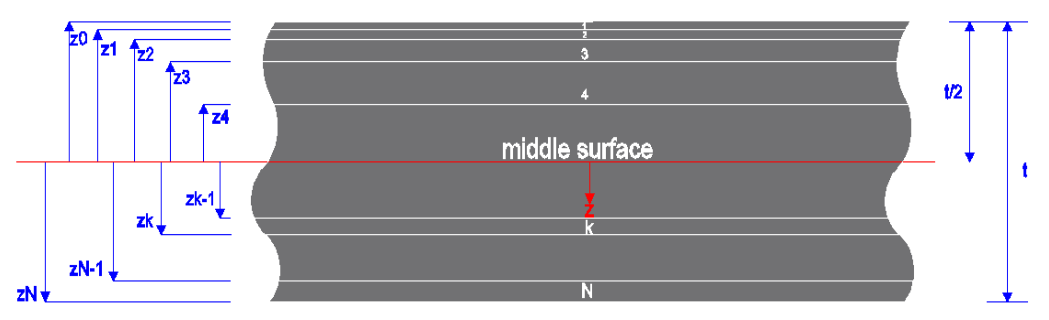
31]:
A i j = t / 2 t / 2 ( Q ¯ i j ) k d z = k = 1 N Q ¯ i j k ( z k z k 1 )
B i j = t / 2 t / 2 ( Q ¯ i j k z d z = 1 2 k = 1 N Q ¯ i j k ( z k 2 z k 1 2 )
D i j = t / 2 t / 2 ( Q ¯ i j ) k z 2 d z = 1 3 k = 1 N Q ¯ i j k ( z k 3 z k 1 3 )
where the subscripts i, j = 1,2, or 6; N are the number of laminas; t is the laminate thickness; z k , and z k 1 are the distances from the middle surface to the inner and outer surfaces of the kth lamina, respectively, as illustrated in Figure 4.
The coupling stiffness matrix couples the in-plane forces with the curvatures and moments with the mid-plane strains. The coupling at laminate is not related to material anisotropy but is due to geometric and/or material property asymmetry with respect to the middle surface. From Equations (21)–(23), Q ¯ i j k are components of the transformed kth lamina stiffness matrix, as follows:
Q ¯ 11 = Q 11 c 4 + Q 22 s 4 + 2 Q 12 + 2 Q 66 s 2 c 2           Q ¯ 12 = Q 11 + Q 22 4 Q 66 s 2 c 2 + Q 12 c 4 + s 4 Q ¯ 22 = Q 11 s 4 + Q 22 c 4 + 2 Q 12 + 2 Q 66 s 2 c 2 Q ¯ 16 = Q 11 Q 12 2 Q 66 c 3 s Q 22 Q 12 2 Q 66 cs 3 Q ¯ 26 = Q 11 Q 12 2 Q 66 cs 3 Q 22 Q 12 2 Q 66 c 3 s Q ¯ 66 = Q 11 + Q 22 2 Q 12 2 Q 66 s 2 c 2 + Q 66 s 4 + c 4
where c = cos θ, s = sin θ, and θ are the lamina orientation angles, while Q i j are the components of the lamina stiffness matrix, which are related to the engineering constants, as follows:
Q 11   = E 1 1 ν 12 ν 21 ,   Q 12   = ν 12 E 2 1 ν 12 ν 21 ,   Q 22   = E 2 1 ν 12 ν 21 ,   Q 66   = G 12
in which E 1 and E 2 are the moduli of elasticity of the lamina in the longitudinal and transverse directions, respectively, ν 12 and ν 21 are the corresponding Poisson’s ratios, respectively, and G 12 is the shear modulus of the lamina.

2.4. Transition Elements and Final Assembling

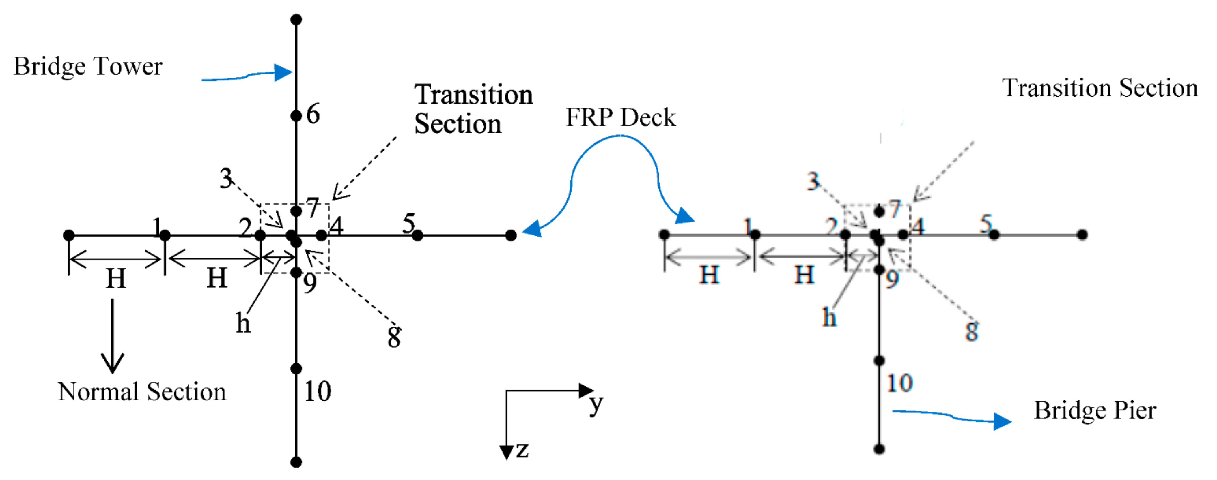
The concept “element” in the longitudinal direction is not defined in the finite strip method. In order to solve this issue, a special transition section has been developed within the IFSM which is applied to connect the FRP deck and the piers, tower, and cables. The transition section is developed by using unequal spaced B3-spline functions. The bearings can be modeled as special boundary conditions for the transition section. Two typical transition sections, one for connecting the deck with the pier and the other for connecting the tower, deck, and cables, are shown in Figure 5. Assuming that the width of the normal and transition sections are H and h, respectively, one can consider the vertical line as a nodal line on the pier or tower strip and the horizontal line as a nodal line on the laminated FRP deck strip. The vertical and horizontal lines overlap at knots 3 and 8 of the deck and the pier (tower) strips, respectively. To model a fixed bearing, which allows rotations but restricts translations, knots 3 and 8 should have the same displacement values to achieve compatibility. In order to have identical displacements at knots 3 and 8, the ratio of h / H should be extremely small. Using the developed transition section, compatibility for the displacements of the different components of the bridge is satisfied in the IFSM.
The principle of minimum potential energy can be used to derive the bending and dynamic properties of the laminate strips, column strips, and cable strips. For instance, the stiffness matrix k F R P of a laminate FRP strip i are given by:
k F R P = B i T D F R P B i d V
in which B and D F R P are the strain and material property matrices of the laminate strip, respectively. In a similar manner, the mass matrix of a laminate FRP strip m F R P is presented by:
m F R P = N i T ρ N i d V
in which ρ is the mass density of the strip and t is the thickness of the strip.
In the IFSM, the strip properties are converted to knots along the nodal lines during the simulation process; however, the number of required knots is significantly reduced compared to the FEM due to the semi-analytical nature of the IFSM. The stiffness and mass matrices of all the strips are assembled using the conventional assembling procedure from which the global stiffness matrix K and global mass matrix [M] are formed. Therefore, the entire 3D model of the hybrid FRP bridge is built using IFSM. The boundary conditions are then applied as described in the following section.

2.5. Boundary Conditions

The strip in the finite strip method must be accompanied by predefined boundary conditions. In spite of the advantages of the spline finite strip method over the finite element method in terms of computational efficiency, however, handling a complex amended scheme of local splines for considering the end and internal boundary conditions makes the solution untidy. In other words, the current amended schemes for boundary conditions are unable to be generalized and dealing with boundary conditions using standard techniques such as penalty functions is complicated.
Therefore, a straightforward method for modeling boundary conditions based on replacing the spline displacement parameters with physical degrees of freedom is proposed herein. This will result in a general unified formulation of otherwise very complex and tedious amended schemes for local splines in the vicinity of the boundary supports and at any internal support. This makes the method more versatile and adjustable with regard to other numerical techniques such as finite element and boundary element methods.
Dividing a spline strip into m equal sections will give 8(m + 3) spline parameters that define the displacement function of the shell spline strip. Similarly, the displacements and rotations of the intermediate knots are also presented by the spline parameters. The transformation matrix corresponding to each degree of freedom u i , v i , w i , θ i , u j , v j , w j , and θ j is expressed by:
T = 1 2 h 0 1 6 4 6   1 2 h   1 6   1 6 4 6   1 6 z e r o z e r o 1 6   4 6 1 6 1 6 1 2 h   4 6 1 6   0 1 2 h  
where h is the spline section length and T is an 8 × 8 (m + 3) matrix. The global transformation matrix of a flat shell spline strip is presented as:
T t = T T T T T T T T
Therefore, the transformed stiffness and mass matrices K t and M t can be obtained by:
K t = T t T K T t
M t = T t T M T t
After transferring all degrees of freedom to the physical coordinate system, for each restrained degree of freedom a corresponding zero value is imposed on the physical displacement vector, which means that the corresponding rows and columns in the structural and aerodynamic properties matrices are eliminated. The proposed amended scheme is more applicable to equal section splines, while for unequal section splines the penalty function is used.

2.6. Frequency Analysis of FRP Bridge Using IFSM

A standard eigenvalue analysis between the transformed mass matrix M t and stiffness matrix K t of the FRP bridge provides the natural frequencies and mode shapes of the structure:
M t δ ¨ + K t δ = 0
where δ is the displacements vector and δ ¨ 
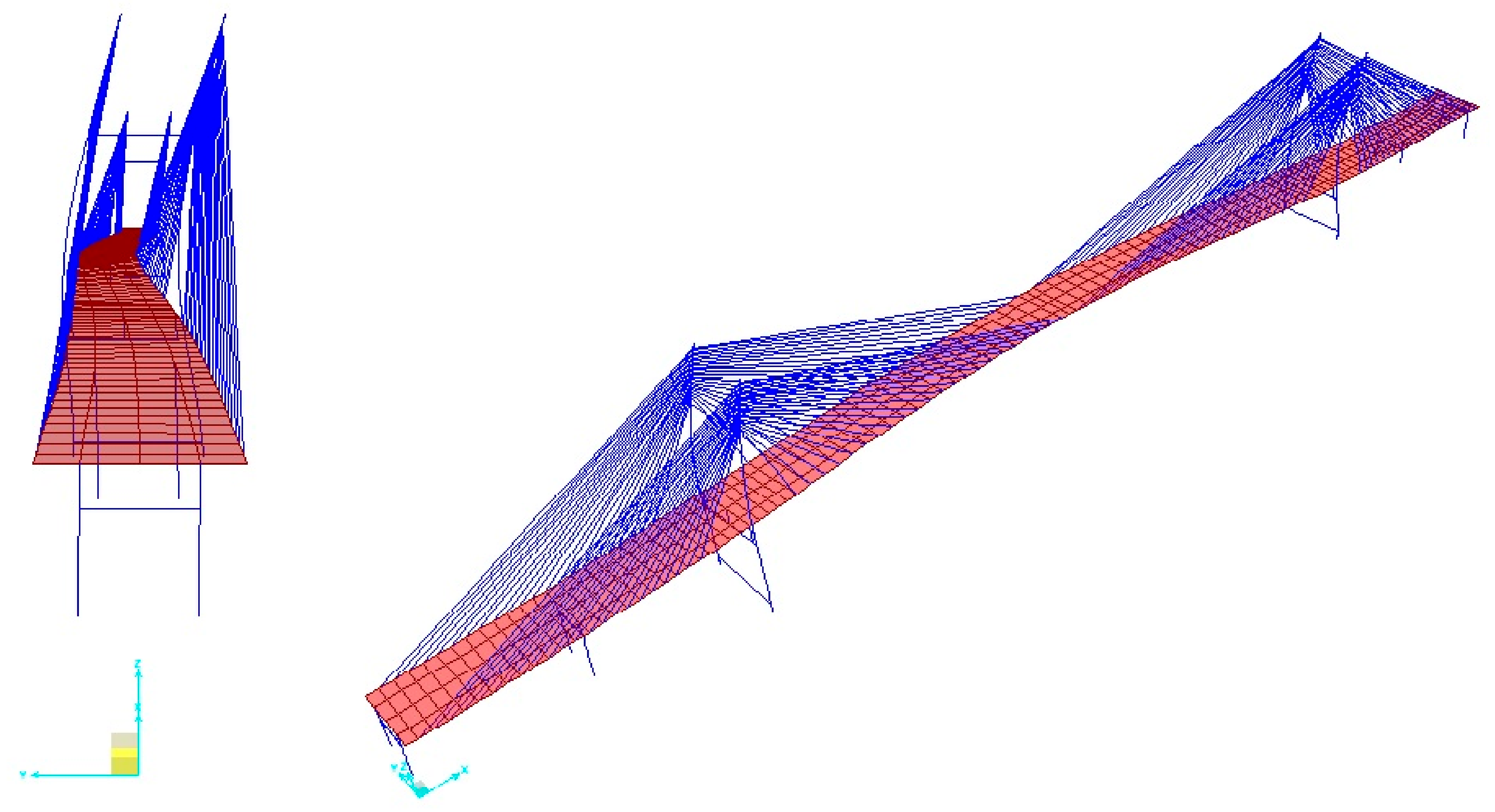
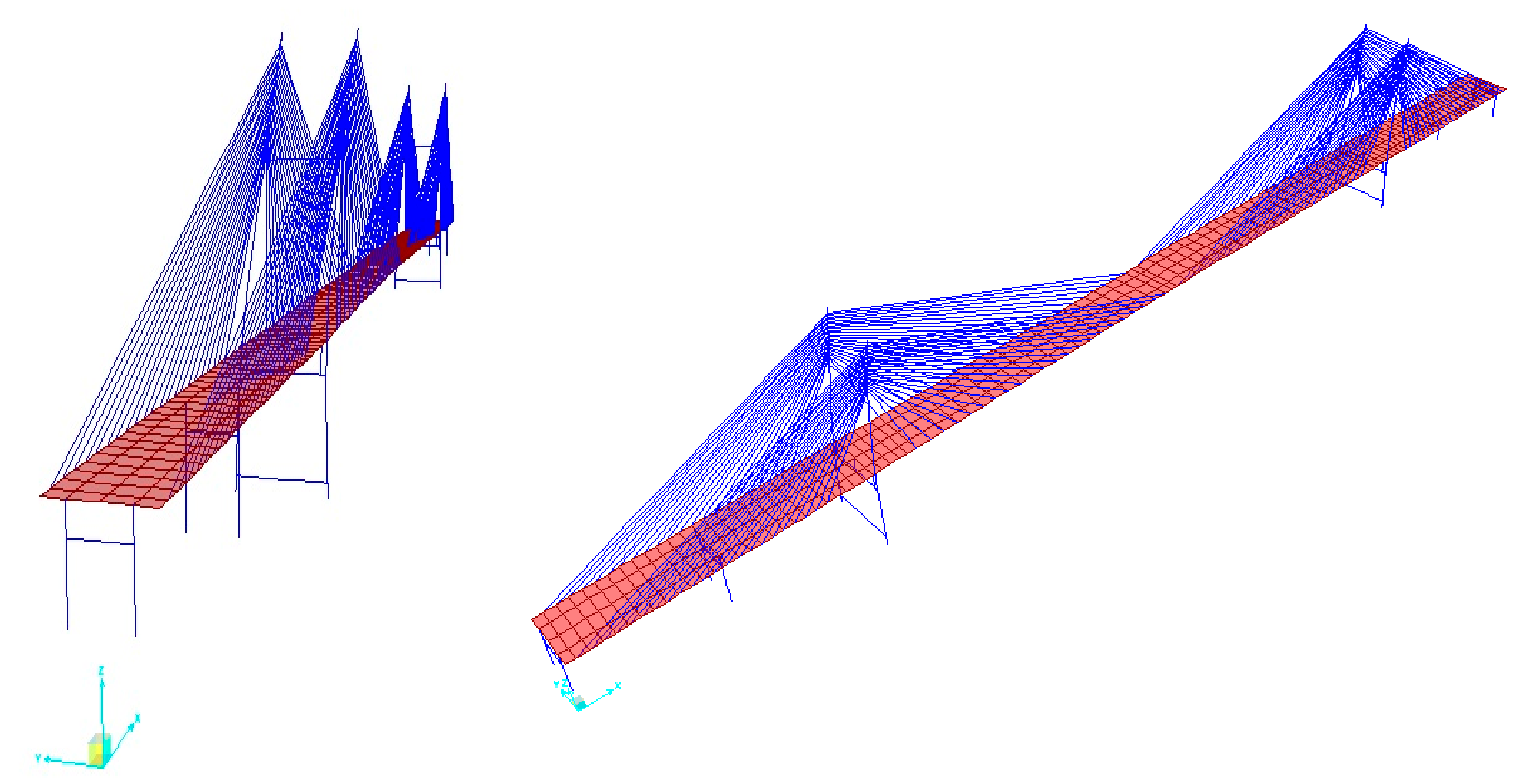
is the vector of the second derivative of the displacements. The eigenvalues and eigenvectors of Equation (32) correspond to the natural frequency and mode shapes of the FRP bridge. Accurate free vibration estimation is an essential factor in complicated dynamic analyses of bridge structures such as earthquake-resistant and aerodynamic flutter designs. The dynamic characteristics are highly influenced by the free vibration behavior of the hybrid FRP bridge. In bridge structures, especially in long-span cable-stayed and suspension bridges, in some cases, the dominant mode shape can occur in the towers instead of the deck [7]. The IFSM is capable of considering the vibration mode shapes not only of the deck but also of tower dominant modes. This is another advantage of using the IFSM in bridge analysis, including FRP bridge systems.

3. Numerical Examples

In this section, two test cases are presented. The first test case is meant to demonstrate the accuracy of the proposed scheme in comparison with highly accurate finite element methods, and the second case is an application of the method to a real-life engineering example of a ULSCSB system.

3.1. Accuracy Test of Integrated Finite Strip Procedure

To verify the accuracy and efficiency of the proposed integrated spline finite strip technique and the integrity of the laminate spline strips with a transition element as well as columns strips, a short-span hybrid FRP slab-girder bridge, as shown in Figure 6, is studied. The layout of the FRP-laminated deck consists of 10 layers of 2 cm-thickness carbon fiber reinforced polymer (CFRP) lamina with orientation configurations of 0, 90, 0, 90, 0, 0, 90, 0, 90, and 0 degrees. The FRP is made of CFRP (IM6G/3501-6) with the following properties: mass density ρ = 1600   ( kg / m 3 ), E 1 = 147   GPa , E 2 = 10   GPa , G 12 = 7   GPa , and ν 12 = 0.25. The pier is made from concrete with a modulus of elasticity of E = 3.0 × 10 4   MPa , a Poisson’s ratio of 0.2, and a material density of 2500 kg/m3. Both IFSM and FEM are adopted to model the free vibration behavior of the structure, and the results are compared. For finite element modeling and analysis, SAP 2000 [32] software has been used.
The full bridge model is constructed using laminate strips for the FRP deck, 3D column strips (CS) for the pier, and transition section elements for the bearings. The deck is divided into four equal strips, and the pier is divided into two CSs. Each deck strip is composed of 32 sections in addition to two transition sections. Each pier strip is composed of four sections and one transition section. For the FEM, the mass and stiffness of a bridge are considered as having five degrees of freedom shell elements throughout the structure. The deck is meshed with 32 by 4 elements, and the pier is meshed with 4 by 2 elements.
Table 1 compares the first seven natural bending frequencies of the models obtained by the IFSM and FEM. The very small deviation of the modal frequencies between the two methods demonstrates that the integrated approach is capable of capturing the free vibration characteristics of an FRP bridge, whereas the minor deviation is likely to be caused by slight differences in mass distribution within different elements. The deformed shapes of the FRP slab girder bridge for the first seven natural modes are illustrated in Figure 7.
Based on this case study, executed on a personal computer for free vibration analysis using similar IFSM and FEM meshes, a 10% reduction in computation time was achieved. It should be noted that the number of sections for each strip in the IFSM model could have been further reduced without losing accuracy and consequently, the computation time could be even further reduced. In addition, this study was only a simplified bridge model while for a large complicated structural model and under complex computations such as smart structural health monitoring in which a continuous real-time iterative vibration analysis is required, the efficiency of the proposed integrated finite strip solution will be more highlighted.

3.2. Long-Span Cable-Stayed Hybrid FRP Bridge

In order to evaluate the accuracy of the proposed integrated finite strip modeling for the free vibration analysis of hybrid FRP long-span cable-stayed bridges, the Kap Shui Mun Bridge, shown in Figure 8, is taken as the reference model. In addition, to examine the integrated finite strip results and the performance of the proposed system, a 3D finite element model is constructed with SAP 2000 [32]. The composite laminated FRP deck is modeled by shell layered linear finite elements.
The Kap Shui Mun Bridge, located in the Lantau Link, provides direct access to Hong Kong International Airport. The total length of the bridge is 820 m, which classifies the Kap Shui Mun Bridge as the world’s second-longest cable-stayed bridge carrying both road and rail traffic. It is a double-decked bridge that has a dual three-lane expressway on the upper deck and two railway tracks and two sheltered single-lane carriageways on the lower deck. The bridge is supported by two concrete pylons with heights of 145 m and 133 m on the west and east sides, respectively. The legs of each tower were constructed by a jump form process and were joined together with post-tensioned struts [33]. The tops of the towers were also post-tensioned to resist the bursting forces caused by the stay cable anchorages. The entire bridge is supported by 176 stay cables made up of 51 to 102 high-tensile steel strands. The bridge was opened to traffic in May 1997 after 54 months of construction. The IFSM and FEM models of the original Kap Shui Mun Bridge have been constructed and calibrated using site experiment data which are highly idealized [7].

3.2.1. Specifications of Carbon Fiber Reinforced Plastic (CFRP) Deck System

The design of the cross-section of the laminated FRP deck is influenced by some major considerations, including long-span cable-stayed bridge requirements and advanced material properties, and macro/structural design requirements. Although glass fiber reinforced polymer (GFRP) can satisfy the strength requirement at a much lower cost, the deflection of the middle span is too large for its low Young’s modulus, as reported in [16]. After testing different types of FRP materials, carbon fiber reinforced polymer with the following properties was proposed by Cheung et al. [17] as the core material for the deck section, i.e., CFRP (IM6G/3501-6) with a mass density of ρ = 1600   ( kg / m 3 ), modulus of elasticity along the longitudinal direction of E 11 = 147   GPa , modulus of elasticity along the transverse direction of E 11 = 10   GPa , shear modules of G 12 = 7   GPa , and the major Poisson ratio of ν 12 = 0.25. A square tube-based FRP box girder deck system, as illustrated in Figure 9, is suggested to replace the steel-concrete deck [25].

3.2.2. Integrated Finite Strip Modelling of FRP Cable-Stayed Bridge

Here, a thin laminated flat FRP deck has been chosen for the bridge composite deck and has been modeled such that it has properties compatible with the deck designed by Chaw [25] in terms of cross-section area, FRP material properties, and angles of lamina orientation in the FRP laminated deck system. The composite hybrid FRP deck is modeled by using the laminate spline strips developed in this paper. There are 38 CFRP lamina layers of 1.0 cm thickness, as introduced in the previous section, with orientation configurations in the sequence 0, 90, 0, 0, 90, and 0 degrees.
The concrete pylons and other piers and linked beams are modeled by one-dimensional column strips, while the cables are modeled by one-dimensional cable strips. The pre-stress condition in the cables is also included in the current analysis. All the interaction points between the different structural elements, including the hybrid FRP deck, pylons, piers, and link beams are modeled by transition section elements.

3.2.3. Free Vibration Analysis of the FRP Cable-Stayed Bridge

One of the most important factors in the dynamic and aerodynamic performance of cable-stayed bridges originates from the free vibration and natural frequency properties of the bridge. For instance, identification of the dominant mode shape of a cable-stayed bridge can predict the aeroelastic behavior of the bridge in flutter or buffering responses. In this section, a free vibration analysis of the selected long-span cable-stayed FRP bridge in the IFSM is performed through which the natural frequencies, as well as dominant mode shapes of the FRP structure, are identified.
Using the overall mass and stiffness matrices, eigenvalue analysis can estimate the natural frequency of an FRP bridge system as well as any deformed shape of the bridge structure through the eigenvalue and eigenvectors, respectively. The first five dominant frequencies of each mode shape, including towers and lateral, vertical, and torsional modes, are classified and presented in Table 2, Table 3, Table 4, Table 5, respectively. The frequencies obtained by the integrated finite strip method are compared with the free vibration finite element analysis, and the percentage of the difference between the results is listed in the tables. In all cases, a good agreement is witnessed between the results, although the natural frequencies predicted by the IFSM are slightly higher than those obtained by the FE analysis. In the case of torsional mode shapes, as seen in Table 5, the difference between the results is significantly greater. The reason for the difference between the results could be because of different distributions of the mass properties between the elements of the FE model. In general, however, the percentage of error in most cases is less than 10%. According to the results, the best agreement between the results is observed in the cases of the vertical bending and tower modes. It can be concluded that the tower dominant modes are well predicted in the IFSM. The deformed shapes of the first symmetric and antisymmetric mode shapes of each specific vibration mode of the FRP cable-stayed bridge are displayed in Figure 10, Figure 11, Figure 12, Figure 13, Figure 14, Figure 15, Figure 16, Figure 17.
In order to investigate the effects of an FRP deck under the vibration behavior of a long-span cable-stayed bridge, a comparison study is made between the natural frequencies and mode shapes of the original model of the Kap Shui Mun Bridge with those of the FRP bridge model. The first ten mode shapes and corresponding natural frequencies of the original Kap Shui Mun Bridge and the hybrid FRP version are presented in Table 6. As can be seen, the dominant mode in both cases is the tower (pylon) swaying mode. Additionally, it appears that the torsional mode is more likely to occur at lower frequencies in the hybrid FRP bridge than in the original Kap Shun Mun Bridge. The torsional free vibration mode is an important factor in the aerodynamic flutter stability of long-span cable-stayed bridges, and therefore, special considerations need to be provided in the design of hybrid FRP cable-stayed bridges for the flutter phenomenon.
Herein, the natural frequencies of the hybrid FRP cable-stayed bridge are found to be generally lower than those of the original Kap Shui Mun Bridge. The total weight of the bridge deck is reduced due to the use of FRP materials instead of steel-concrete and it is expected to provide relatively high stiffness which is compatible with a conventional concrete-steel cable-stayed bridge. Therefore, the stiffness to mass ratio and subsequently the natural frequencies are expected to be higher in the case of an FRP bridge. It can be concluded that the stiffness of the proposed FRP deck needs to be modified by increasing the thickness of the laminated FRP deck or by considering alternative sequences of ply angles or by adopting another type of FRP material. Regardless of the concluding remarks of the results, the present study proves that the dynamic behavior of the cable-stayed FRP bridge is different from the existing Kap Shui Mun Bridge with a concrete deck.

4. Concluding Remarks

An efficient integrated finite strip framework was deployed for hybrid FRP bridges in the environment of the spline finite strip method. The laminate strip was introduced, which can model an FRP deck considering the coupling effects between the in-plane and out-of-plane degrees of freedom as well as the anisotropic material properties of the laminated FRP deck. The other components of the bridge can also be modeled by spline-based finite strips. The 1D column strips model the piers and towers, while cable strips model the cables. Transition section elements combine strips with different orientations. A straightforward method for modeling boundary conditions based on replacing the spline displacement parameters with physical degrees of freedom was proposed as well. The application of the laminate strip along with the integrated finite strip method resulted in a very precise and efficient numerical technique for modeling cable-stayed hybrid FRP bridges. The proposed finite strip scheme was extended for the free vibration analysis of hybrid FRP bridges. The finite strip results for the natural frequencies and mode shapes of a cable-stayed FRP bridge were compared with those obtained by the finite element method, and a very good agreement was witnessed.
Among the advantages of the proposed solution are its high efficiency and accuracy as well as the minimal computational time and simplicity of the input data. Moreover, the structural interactions between different bridge components can be handled. Consequently, dynamic analysis of an FRP bridge for occurrences such as earthquakes, in which there are significant structural interactions between towers, piers, linked beams, cables, and decks can be easily performed.
The present methodology can be expanded to nonlinear and time-history analyses of FRP bridge structures, as well as flutter and buffeting of FRP bridges. Last but not least, this IFSM can be merged well with smart structural health monitoring systems of long-span bridges as well as high-rise buildings such as telecommunication towers, where a continuous real-time vibration analysis and iterative dynamic analysis must be performed.

Author Contributions

Conceptualization, H.N. and M.M.S.C.; methodology, H.N. and M.M.S.C.; software, Matlab, C++, validation, H.N. and E.D.; formal analysis, H.N.; investigation, M.M.S.C. and A.M.; resources, M.M.S.C., E.D. and A.M.; data curation, H.N., M.M.S.C., E.D. and A.M.; writing—original draft preparation, H.N.; writing—review and editing, E.D. and A.M.; visualization, H.N.; supervision, M.M.S.C., E.D. and A.M.; project administration, H.N.; funding acquisition, M.M.S.C., H.N., E.D. and A.M. All authors have read and agreed to the published version of the manuscript.

Funding

This research was funded by of Canada (NSERC), the Industrial Postgraduate Scholarship, and the Discovery Grants Program.

Data Availability Statement

The processed data required to reproduce these findings are available by contacting the first author at [email protected].

Conflicts of Interest

The authors declare no conflict of interest.

References

  1. Cheung, M.S.; Li, W.; Chidiac, S.E. Finite Stri Analysis of Bridges, 1st ed.; E & FN Spon: London, UK, 1996. [Google Scholar]
  2. Cheung, Y.K. Finite Strip Method in Structural Analysis; Pergamon Press: Adelaide, Australia, 1976; Volume 3, No. 2. [Google Scholar]
  3. Cheung, Y.K. The Finite Strip Method in the Analysis of Elastic Plates with two opposite Simply Supported Ends. Proc. Inst. Civ. Eng. 1969, 40, 1–7. [Google Scholar] [CrossRef]
  4. Li, Z.; Schafer, B.W. Buckling Analysis of Cold-formed Steel Members with General Boundary Conditions Using CUFSM Conventional and Constrained Finite Strip Methods. In Proceedings of the CCFSS Proceedings of International Specialty Conference on Cold-Formed Steel Structures, St. Louis, MI, USA, 3–4 November 2010. [Google Scholar]
  5. Ádany, S.; Schafer, B.W. Buckling analysis of cold-formed steel members using CUFSM: Conventional and constrained finite strip methods. In Proceedings of the 18th International Specialty Conference on Cold-Formed Steel Structures, Orlando, FL, USA, 26–27 October 2006. [Google Scholar]
  6. Lazzari, J.A.; Batista, E.M. Finite strip method computer application for buckling analysis of thin-walled structures with arbitrary cross-sections. REM Int. Eng. J. 2021, 74, 337–344. [Google Scholar] [CrossRef]
  7. Naderian, H.; Cheung, M.S.; Dragomirescu, E.; Mohammadian, M. Integrated finite strip flutter analysis of bridges. Comput. Struct. 2019, 212, 145–161. [Google Scholar] [CrossRef]
  8. Naderian, H.; Cheung, M.S.; Shen, Z.; Dragomirescu, E. Seismic analysis of long-span cable-stayed bridges by an integrated finite strip method. ASCE J. Bridge Eng. 2016, 21, 04015068. [Google Scholar] [CrossRef] [Green Version]
  9. Shen, Z.; Cheung, M.S.; Naderian, H.; Dragomirescu, E. An Integrated Finite Strip Solution for Dynamic Analysis of Continuous Multi-span Bridges. In Proceedings of the 3rd Specialty Conference on Mechanics and Materials, Montreal, QC, Canada, 29 May–1 June 2013. [Google Scholar]
  10. Camotim, D.; Silvestre, N.; Bebiano, R. GBT-based local and global vibration analysis of thin-walled members. In Analysis and Design of Plated Structures; Woodhead, P., Shanmugam, N.E., Wang, C.M., Eds.; Elsevier: Cambridge, UK, 2007; pp. 36–76. [Google Scholar]
  11. Bebiano, R.; Silvestre, N.; Camotim, D. Local and global vibration of thin walled members subjected to compression and non-uniform bending. J. Sound Vib. 2008, 315, 509–535. [Google Scholar] [CrossRef]
  12. Bebiano, R.; Camotim, D.; Silvestre, N. Dynamic analysis of thin-walled members using Generalised Beam Theory (GBT). Thin-Walled Struct. 2013, 72, 188–205. [Google Scholar] [CrossRef]
  13. Bebiano, R.; Camotim, D.; Gonçalves, R. GBTul 2.0—A second-generation code for the GBT-based buckling and vibration analysis of thin-walled members. Thin-Walled Struct. 2018, 124, 235–257. [Google Scholar] [CrossRef]
  14. Qin, X.C.; Dong, C.Y.; Yang, H.S. Isogeometric vibration and buckling analyses of curvilinearly stiffened composite laminates. Appl. Math. Model. 2019, 73, 72–94. [Google Scholar] [CrossRef]
  15. Guo, X.; Zhang, B.; Cao, D.; Sun, L. Influence of nonlinear terms on dynamical behavior of graphene reinforced laminated composite plates. Appl. Math. Model. 2020, 78, 169–184. [Google Scholar] [CrossRef]
  16. Salim, H.A.; Davalos, J.F.; Qiao, P.; Kiger, S.A. Analysis and design of fiber reinforced plastic composite deck-and-stringer bridges. Compos. Struct. 1997, 38, 295–307. [Google Scholar] [CrossRef]
  17. Qiao, P.; Julio, F.; Davalos, B.; Brown, B. A systematic analysis and design approach for single-span FRP deck/stringer bridges. Compos. Part B 2000, 31, 593–609. [Google Scholar] [CrossRef]
  18. Zhang, Q.W.; Chang, T.Y.P.; Chang, C.C. Finite-Element Model Updating for the Kap Shui Mun Cable-Stayed Bridge. J. Bridge Eng. 2001, 6, 285–293. [Google Scholar] [CrossRef]
  19. Almansour, H.; Cheung, M.S. Structural performance of laminated FRP box girder bridge deck compared to slab on prestressed concrete girder bridge. In Proceedings of the 8th Canada Japan Joint Workshop on Composites, Montreal, QC, Canada, 26–29 July 2010; pp. 1–32. [Google Scholar]
  20. Almansour, H.H.; Cheung, M.S.; Chan, B.Y. Analysis and design of hybrid long span cable-stayed bridges using multi-scale modeling techniques. In Proceedings of the International Conference on Computing in Civil and Building Engineering, the University of Nottingham, Nottingham, UK, 30 June–2 July 2010. [Google Scholar]
  21. Almansour, H.H.; Cheung, M.S. Finite element modeling of a CFRP composite deck for long span cable-stayed bridge. In Proceedings of the Third Japan-Canada Joint Conference on New Applications of Advanced Composites, Nagano, Japan, 13–15 March 2003. [Google Scholar]
  22. Almansour, H.H. The Performance of Hybrid Long-Span Cable-Stayed Bridges Using Advanced Composites; Department of Civil and Environmental Engineering, The University of Ottawa: Ottawa, ON, USA, 2006. [Google Scholar]
  23. Virlogeux, M. Recent evolution of cable-stayed bridges. Eng. Struct. 1999, 21, 737–755. [Google Scholar] [CrossRef]
  24. Burgueno, R.; Karbhari, V.M.; Seible, F.; Kolozes, R.T. Experimental dynamic characterization of an FRP composite bridge, superstructure assembly. Compos. Struct. 2001, 54, 427–444. [Google Scholar] [CrossRef]
  25. Chao, W. Damage Modelling of FRP Composite Bridge Decks. Ph.D. Thesis, Department of Civil and Environmental Engineering, Hong Kong University of Science and Technology, Hong Kong, China, 2015. [Google Scholar]
  26. Chan, B.Y.; Cheung, M.; Wang, C. Nonlinear dynamic analysis of fiber reinforced ultra-long span cable stayed bridges. J. Bridge Struct. 2013, 9, 3–19. [Google Scholar] [CrossRef]
  27. Zhao, P.; Xie, L.; Cheung, M.M. Analysis and design procedure of hybrid long-span cable-stayed bridge using advanced composite material. J. Reinf. Plast. Compos. 2015, 34, 1557–1580. [Google Scholar]
  28. Adekanye, O.; Washington, T. Nonstandard finite difference scheme for a Tacoma Narrows Bridge model. Appl. Math. Model. 2018, 62, 223–236. [Google Scholar] [CrossRef]
  29. Arioliab, G.; Gazzolab, F. A new mathematical explanation of what triggered the catastrophic torsional mode of the Tacoma Narrows Bridge. Appl. Math. Model. 2015, 39, 901–912. [Google Scholar] [CrossRef]
  30. Au, F.; Cheng, Y.S.; Cheung, Y.K.; Zheng, D.Y. On the determination of natural frequencies and mode shapes of cable-stayed bridges. Appl. Math. Model. 2001, 25, 1099–1115. [Google Scholar] [CrossRef]
  31. Gibson, R.F. Principles of Composite Material Mechanics; CRC Press: Boca Raton, FL, USA, 2012. [Google Scholar]
  32. CSI. SAP2000 Integrated Software for Structural Analysis and Design; Computers and Structures Inc.: Berkeley, CA, USA, 2000. [Google Scholar]
  33. Kap Shui Mun Bridge, Highways Department—The Government of the Hong Kong Special Administrative Region. Available online: https://www.hyd.gov.hk/en/information_corner/hyd_factsheets/doc/e_Kap_Shui_Mun_Bridge.pdf (accessed on 13 February 2022).
Figure 1. Multi-layer composite plate divided by laminate finite strips.
Mca 27 00047 g001
Figure 2. Laminate spline finite strip.
Mca 27 00047 g002
Figure 3. Column strip in local coordinate system (CS).
Mca 27 00047 g003
Figure 4. Laminated plate cross-sectional geometry and ply numbering system.
Mca 27 00047 g004
Figure 5. Typical transition section elements for tower (left) and pier (right).
Mca 27 00047 g005
Figure 6. A simple FRP bridge.
Mca 27 00047 g006
Figure 7. Mode shapes of the FRP deck bridge.
Mca 27 00047 g007
Figure 8. Kap Shui Mun Bridge [33].
Mca 27 00047 g008
Figure 9. Design of the FRP bridge deck system (dimensions are in meters) [25].
Mca 27 00047 g009
Figure 10. Symmetric lateral mode shape of the FRP cable-stayed bridge (0.5725 Hz).
Mca 27 00047 g010
Figure 11. Antisymmetric lateral mode shape of the FRP cable-stayed bridge (1.003 Hz).
Mca 27 00047 g011
Figure 12. Symmetric torsional mode shape of the FRP cable-stayed bridge (0.5027 Hz).
Mca 27 00047 g012
Figure 13. Antisymmetric torsional mode shape of the FRP cable-stayed bridge (0.6290 Hz).
Mca 27 00047 g013
Figure 14. Symmetric tower dominant mode shape of the FRP cable-stayed bridge (0.1986 Hz).
Mca 27 00047 g014
Figure 15. Antisymmetric tower dominant mode shape of the FRP cable-stayed bridge (0.2245 Hz).
Mca 27 00047 g015
Figure 16. Symmetric bending mode shape of the FRP cable-stayed bridge (0.3354 Hz).
Mca 27 00047 g016
Figure 17. Antisymmetric bending mode shape of the FRP cable-stayed bridge (0.4009 Hz).
Mca 27 00047 g017
Table 1. Natural frequency of the FRP deck bridge.
Mode NumberFrequency (Hz)Mode Shape
IFSMFEM
12.082.00Heave (deck) antisymmetrical
23.383.11Heave (deck) symmetrical
38.087.90Heave (deck) antisymmetrical
410.789.90Heave (deck) symmetrical
517.5917.33Torsional (deck) antisymmetrical
619.6019.96Torsional (deck) symmetrical
729.4729.38Heave (deck) antisymmetrical
Table 2. Natural frequencies of the tower dominant modes.
Mode NumberIFSM (Hz)FEM (Hz)Error %
10.190.190.0
20.220.214.5
31.131.102.6
41.131.102.6
51.331.274.5
Table 3. Natural frequencies of the deck lateral dominant modes.
Mode NumberIFSM (Hz)FEM (Hz)Error %
10.570.553.5
21.000.982.0
33.923.705.6
45.625.305.6
55.975.734.0
Table 4. Natural frequencies of the deck vertical dominant modes.
Mode NumberIFSM (Hz)FEM (Hz)Error %
10.330.323.0
20.400.385.0
30.670.661.4
40.790.772.5
50.880.871.1
Table 5. Natural frequencies of the deck torsional dominant modes.
Mode NumberIFSM (Hz)FEM (Hz)Error %
10.500.4510.0
20.620.578.0
31.131.057.0
41.291.234.6
51.431.355.5
Table 6. Vibration specifications of original and FRP bridges.
Mode NumberFRP BridgeMode ShapeOriginal Bridge [8]Mode Shape [8]
10.19tow 10.21tow 1
20.22tow 20.24tow 2
30.33V10.42V1
40.40V20.52L1
50.50T10.75T1
60.57T20.85V2
70.62L10.93L2
80.67V31.00V3
90.79V41.13tow 3
100.88V51.14tow 4
Publisher’s Note: MDPI stays neutral with regard to jurisdictional claims in published maps and institutional affiliations.

