
Simulation of a Thermal Recuperative Incinerator of VOCs with a Special Focus on the Heat Exchanger


1
IDMEC, Escola de Ciências e Tecnologia, Universidade de Évora, R. Romão Ramalho 59, 7000-671 Évora, Portugal
2
Instituto de Ciências da Terra, Escola de Ciências e Tecnologia, Universidade de Évora, R. Romão Ramalho 59, 7000-671 Évora, Portugal
3
CCEnergia, Pavilhão Multiusos, Av. Dr. Mário Soares, 2040-413 Rio Maior, Portugal
*
Author to whom correspondence should be addressed.
Math. Comput. Appl. 2024, 29(1), 1; https://doi.org/10.3390/mca29010001
Submission received: 3 November 2023
/
Revised: 18 December 2023
/
Accepted: 21 December 2023
/
Published: 23 December 2023
(This article belongs to the Special Issue Numerical and Symbolic Computation: Developments and Applications 2023)
Abstract
:Simulation and modeling of thermal recuperative incinerators may play an important role in enhancing efficiency and ensuring compliance with environmental regulations. In this context, the primary objective of this study is to simulate and comprehensively understand the operation of a geometrically complex thermal recuperative incinerator with an integrated preheater featuring varying levels of heat recovery. To achieve this objective, a simple yet effective 0D model was developed. This modeling approach allows for a holistic evaluation of the performance of the incinerator, enabling the assessment of key parameters, such as temperatures and heat transfer rates, under varying operating conditions. Successful validation of the model is established by comparing its results with measurements from an industrial thermal recuperative incinerator in operation at a vehicle assembly plant, with maximum relative differences of around 9%. Simulations for different percentages of flue gases bypassing the preheater were conducted, indicating a good compromise between heat transfer and pressure drop and a 22% heat recovery at around 50%. The model presented in this paper provides a robust foundation for comprehensively assessing and optimizing the performance of thermal recuperative incinerators and systems that comprise thermal recuperative incinerators, with implications for waste management and sustainable energy recovery systems.
1. Introduction
The growing concerns over environmental pollution and the need to manage waste efficiently have led to the development of various technologies for waste management, including thermal recuperative incinerators (TRIs) [1]. These incinerators are designed to burn gaseous emissions from industrial processes within a controlled environment, effectively eliminating harmful contaminants [2]. One of the applications of this air pollution control equipment is in automotive paint shops [1,3]. These facilities, in addition to typically being the largest consumers of energy within the vehicle manufacturing processes [4], also stand out as major sources of volatile organic compounds (VOCs) and particulates [1]. VOCs are the primary contributors to emissions in vehicle coating processes, with the main sources being spray booths, drying ovens and the cleaning of application equipment [5]. Paint shop exhaust fumes typically contain evaporated solvents, with some of the commonly used solvents (e.g., xylene, toluene, methyl ethyl ketone) adversely impacting air quality and posing hazards to human health if released to the atmosphere [1].
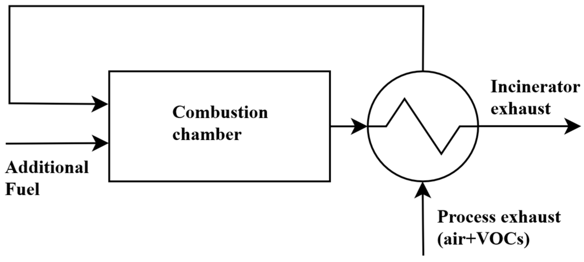
TRIs effectively destroy VOCs through thermal oxidation, converting them into CO2 and H2O [2]. As the name suggests, these systems are equipped with preheat heat exchangers to recover part of the heat from the exhaust gas of the incinerator and transfer it to the gaseous feed stream (Figure 1). Typical heat recovery rates range from 50% to 60% [1] and can reach 70% [6]. Any waste heat not recuperated during the feed stream preheating process can be recovered by additional heat exchangers, providing necessary process heat, as in the case of vehicle manufacturing plants.
The preheat heat exchanger is a critical component of TRIs since it improves the efficiency of the incinerator by reducing the supplemental fuel needed to maintain the temperature required for VOC oxidation. In case of system configurations in which the preheater is separated from the combustion chamber, plate-to-plate and shell-and-tube heat exchangers are most often used [6]. These types of heat exchangers have been extensively used for a long time in various industrial applications [7], while research on their design and optimization continues, with the aim of increasing energy efficiency in industry [8,9,10]. Their reliability and well-established performance characteristics make them a preferred choice in many thermal processes. Plate-to-plate and shell-and-tube heat exchangers are characterized by high efficiencies [11,12,13], which are crucial in TRIs, where maximizing heat transfer is essential for improving overall efficiency. Additionally, these types of heat exchangers (i) offer versatility in terms of design and application, adapting to various operating conditions; (ii) are often designed to be compact, which is advantageous in industrial settings where optimizing spatial efficiency is crucial; and (iii) are able to operate under demanding conditions, including high temperatures and corrosive environments, which ensures durability and longevity [7,10]. However, the heat exchangers often used in thermal recuperative incinerators are complex pieces of equipment, which may have a very intricate internal structure and inaccessible zones [14].
Due to the substantial energy consumption of TRIs in automotive manufacturing, even small increases in their performance result in significant cost savings and environmental benefits. The simulation of TRIs is important as it can help optimize efficiency, ensure environmental compliance, reduce costs, enhance safety and assist in designing and scaling-up these systems. Moreover, simulations help improve process understanding, enabling operators and engineers to better comprehend the complex processes occurring within incinerators, such as combustion, heat transfer and turbulent fluid flow. This understanding is crucial not only for troubleshooting and maintaining these systems but also for identifying ways to enhance combustion efficiency, reduce energy consumption, minimize emissions and, ultimately, destroy VOCs.
Only a limited number of studies exist on the simulation of TRIs [2,15], and the design of such equipment primarily relies on empirical methods [2]. Several modeling approaches are available for simulating thermal recuperative incinerators, with the choice of modeling approach depending on the specific goals of the study, the complexity of the incinerator geometry and available computational resources. For design purposes, detailed computational fluid dynamics models, though rare in the context of TRIs, are essential. However, the complexity of the strongly coupled thermo-chemical and fluid flow phenomena that occur inside the incinerators results in complex and computationally intensive simulations. The work of Salvador et al. [2] is one of the few examples of such an approach. Another example is the work by Crawmer et al. [16], but, in this case, only a cold flow model was briefly presented with no chemical reactions or heat transfer being modeled.
A simpler approach to modeling TRIs involves the use of 0D models based on the integral form of mass and energy balances for steady-state conditions, along with descriptions of combustion and heat transfer processes, including conduction, convection and thermal radiation. These models are suitable for preliminary design [17,18], performance evaluation [19,20], model-based control design [21], the definition of input data and boundary conditions for detailed CFD models [22,23] and feasibility studies [24]. Sorrels et al. [6] present material and energy balances around a thermal recuperative incinerator and its combustion chamber, a central part of TRIs. In their model, these authors make the following assumptions: (i) the mass flow rates on both the hot and cold sides of the preheater are approximately equal; (ii) the heat capacities on both sides of the preheater are approximately the same, regardless of composition and temperature; and (iii) energy losses are considered to be 10% of the total energy input to the incinerator. The first assumption applies when all gases leaving the combustion chamber in the TRI pass through the preheater and the amount of auxiliary fuel is small compared to the incoming waste stream. The second assumption is valid for waste streams that consist of dilute mixtures of VOCs in air, with the properties of the stream changing only slightly upon combustion and changes in temperature. The third assumption also simplifies the model; the heat losses are considered to be of the order of magnitude of typical heat losses in thermal recuperative incinerators [6]. The percentage of heat loss in an incinerator is dependent on factors such as the type of incinerator, the materials used, the quantity and type of insulation and various other influencing factors [6].
In many TRIs, the entire stream of flue gases leaving the combustion chamber passes through the preheater. However, in some designs, all or part of the flue gases can bypass the preheat heat exchanger. This design variation allows for increased flexibility and optimization of the heat exchanger operating conditions by controlling the amount of flue gases that are directly discharged to the exhaust without preheating the incoming flue gases. In this case, the assumption (i) mentioned earlier is no longer applicable. Additionally, the other assumptions made by Sorrels et al. [6] can be eliminated, resulting in more complex models but enhancing accuracy and applicability, as the models are grounded in thermodynamics and heat-transfer calculations.
This work aims to simulate an industrial VOC thermal recuperative incinerator with varying levels of energy recovery, using classical thermodynamics, heat transfer and heat exchanger theory. Various control surfaces enclosing different parts of the incinerator were defined, around which mass and energy balances were made to characterize the operation of the incinerator and assess the effectiveness of heat recovery and the energy available in the flue gases for further energy recovery. The model results were validated using data collected in an industrial context. Furthermore, the performance of the TRI was determined as a function of the amount of flue gases bypassing the heat exchanger, allowing informed adjustment of this parameter for improved performance.
This study introduces a model capable of predicting the operation of a thermal recuperative incinerator with an integrated, geometrically complex preheater that allows for varying energy recovery. The model is entirely based on theoretical considerations, i.e., no parameter adjustments were made to minimize errors between numerical results and instrumentation data obtained at an industrial scale. Despite its relatively simplicity, the model can reproduce the instrumentation data with a maximum deviation of around 9%. The structure of the model developed in this work can be adapted for simulating other designs of thermal recuperative incinerators with necessary adjustments. It proves to be an important tool for evaluating and optimizing the operation of TRIs and thermal systems that include them.
2. Materials and Methods
2.1. Thermal Recuperative Incinerator
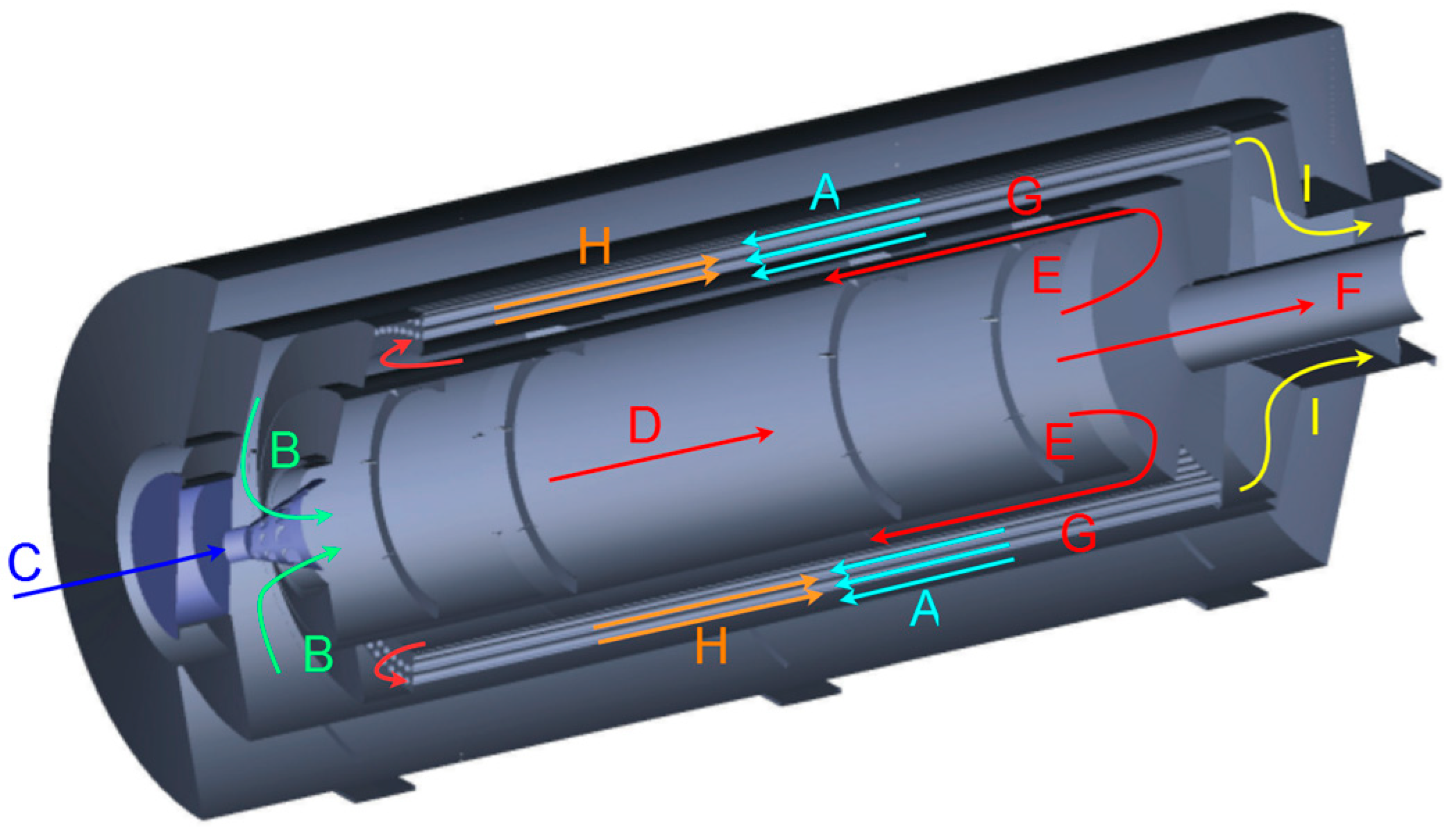
The thermal recuperative incinerator modeled in this work is responsible for the oxidation of the VOCs diluted in the exhaust air from an automotive paint shop oven located in Portugal, Europe. It is a relatively compact, horizontal, gas-fired TRI, with a central combustion chamber and a heat exchanger surrounding the combustion chamber (Figure 2).
The process exhaust stream with VOCs from the paint shop oven enters the incinerator. It flows through the exterior of a tube bundle composed of two concentric layers of tubes around the combustion chamber. Along this flow path (A, from right to left in Figure 2), this colder oven exhaust stream is preheated by the hotter combustion products that flow in counterflow inside the tubes (H) and in co-flow in the jacket that surrounds the combustion chamber (G). The preheated oven exhaust stream then enters the combustion chamber (B), where it burns with the auxiliary fuel (natural gas) fed into the incinerator (C). The combustion reactions raise the temperature inside the combustion chamber and result in the oxidation of the VOCs. At the end of the combustion chamber, the flow of hot flue gases is partitioned, with one part directly leaving the incinerator (F), while the other part enters the heat exchanger (E) and flows through the jacket, between the exterior wall of the combustion chamber and the inner casing that encloses the tubes (G), before entering the tubes. As mentioned above, while flowing along the jacket from right to left (G) and then inside the tubes from left to right (H), the combustion products preheat the incoming oven exhaust stream, decreasing their temperature. After passing inside the heat exchanger, the flue gases flow to the incinerator exhaust chamber (I), mixing with the flue gas flow that bypasses the heat exchanger (F).
2.2. Mathematical Model
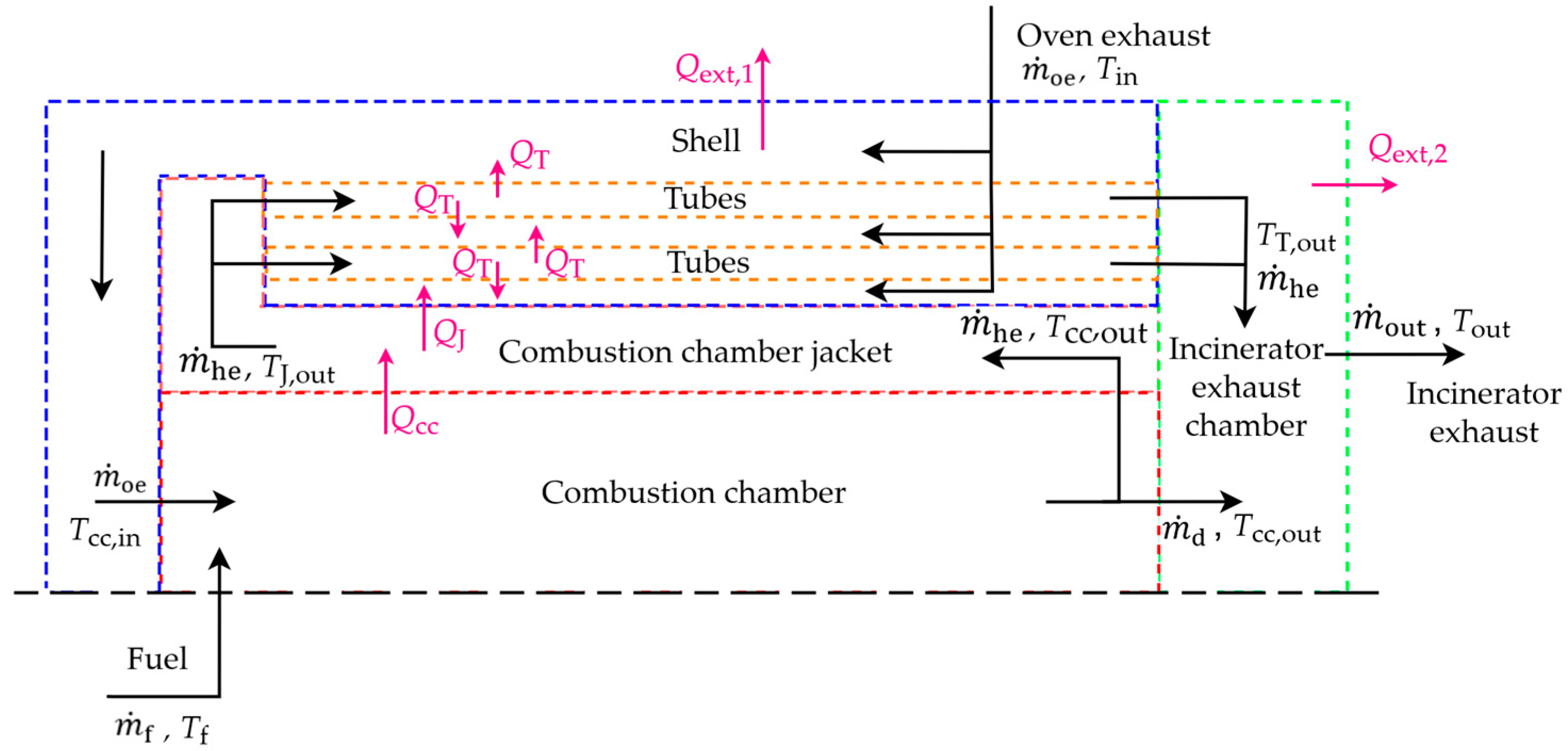
To model the complex TRI described above, the incinerator is divided into five smaller zones: the combustion chamber, the combustion chamber jacket, the tube bundle, the shell that contains the tube bundle and the exhaust chamber (Figure 3).
A mathematical model was developed to determine the mass flow rates and heat transfer rates flowing into and out of each of the five control volumes identified in the incinerator. For each of these five control volumes, the integral mass and energy balance equations were considered [25].
2.2.1. Combustion Chamber
The combustion chamber of the TRI installed in the paint shop is an almost cylindrical enclosure. Derived from CAD drawings, the combustion chamber is geometrically modeled as a cylinder with a diameter of 1.15 m and a length of 4.25 m. Preheated oven exhaust gas at a temperature Tcc,in and fuel at a temperature Tf enter the combustion chamber. The equations of conservation of mass and energy in the combustion chamber are expressed as follows:
The contaminated gas from the oven is a mixture of air and VOCs. Its mass flow rate, , is the sum of the individual mass flow rates of air, , and VOCs, . Due to the low concentration of VOCs, an additional energy source is introduced. represents the mass flow rate of this “additional” fuel, while represents the aggregate mass flow rates of the combustible gases entering the incinerator. The mass flow rate of VOCs is small compared to the mass flow rate of the “additional” fuel and, especially, air. Given the lack of data, the specific composition of VOCs is not considered, and they are treated as the “additional” fuel fed into the incinerator.
Moreover, the total mass flow rate of the flue gases leaving the incinerator, , is determined by the sum of the mass flow rate of flue gases entering the heat exchanger that surrounds the combustion chamber, , with the mass flow rate of flue gases directly leaving the incinerator (i.e., bypassing the heat exchanger), . Key input variables in the model include , , and α, representing the fraction of that bypasses the heat exchanger.
In Equation (2), are, for each species i, respectively, the stoichiometry coefficient of the global combustion reaction, the enthalpy of formation at the standard reference state and the specific heat at constant pressure; LHV is the lower heating value of the fuel; Tcc,out is the temperature at the end of the combustion chamber; TR,i is the temperature of the reactants (Tf for the fuel and Tcc,in for the preheated oven exhaust stream), Tref is the standard-state temperature, 298 K; and Mf is the molar mass of the fuel.
Complementing the equations expressing the conservation of mass and energy, the model incorporates the fundamental equations of heat transfer, which describe the physical mechanisms by which heat is transferred, as illustrated in [26], for example. The rate of heat transferred from the combustion chamber to the flue gases flowing through the jacket, , is determined by:
where is the average temperature in the inner surface of the combustion chamber, is the average temperature of the fluid in the jacket (between Tcc,out and TJ,out) and Rcc is the thermal resistance between the inner surface of the combustion chamber and the fluid in the jacket. This thermal resistance accounts for the conduction through the wall separating the combustion chamber and the jacket, Rcond,cc, and convection between the combustion chamber outer wall and the flue gases that flow inside the jacket, Rconv,cc out. The wall is made of steel, with inner and outer diameters of 1.15 mm and 1.2 mm, respectively.
The same heat transfer rate can also be written as follows:
and is used to determine the average temperature of the inner surface of the combustion chamber. In Equation (4), Rcc,in is the thermal resistance between the fluid in the combustion chamber and the inner surface of the combustion chamber, including the radiation and the convection from the fluid to the inner wall of the combustion chamber. Given the lack of specific data for the emissivity of the inner surface of the combustion chamber, a 0.8 value was assumed as a reasonable estimate, as this wall is coated with a high-temperature coating [27]. To gauge the impact of this assumption on the results, a sensitivity analysis was conducted. The analysis involved varying the emissivity from 0 to 1, and it was found that the deviation in temperature at the end of the combustion chamber was relatively small, 0.1%. While the precise emissivity of the furnace inner wall remains uncertain, this sensitivity analysis helps to understand the potential influence of this parameter on the results. In Equation (4), is the average temperature inside the combustion chamber estimated as the average of the adiabatic flame temperature and the temperature at the end of the combustion chamber.
2.2.2. Combustion Chamber Jacket and Shell Modeled as a Co-Current Heat Exchanger
The temperature at the outlet of the jacket, , is needed for the determination of in Equation (3) and is calculated through the equations that express the conservation of mass and energy in the combustion chamber jacket:
where, by conservation of mass, the mass flow rate that enters the jacket, , is equal to the mass flow rate that leaves the jacket, , and to . The temperature at the inlet of the jacket, , is equal to the temperature at the combustion chamber outlet. On the right-hand side of Equation (6), the specific heats at constant pressure of the flue gases, cp,fg, are evaluated at the corresponding temperature of the fluid.
In Equation (6), the rate of heat transferred from the gases in the jacket to the fluid coming from the oven exhaust, , is calculated with the effectiveness-number of transfer units (-NTU) method [19], which is a well-established method for heat exchanger analysis when the outlet temperatures are unknown. The jacket and shell are analogous to two concentric annuli in the perspective of the energy being transferred through the jacket walls to the oven exhaust stream (Figure 4). The hot flue gas flow in the jacket and the colder oven exhaust gas flow in the shell are in the same direction.
The jacket outer wall, 25 mm thick, has a diameter of 1.3 m and a length of 3.85 m, and the shell outer wall, 25 mm thick, has a diameter of 1.75 m and a length of 4.75 m. Both walls are made of steel.
The jacket-shell system was modeled as a co-current heat exchanger with the hot gases flowing in the inner annulus and the colder gases flowing in the outer annulus. The effectiveness equation, according to [28], used for the parallel (co-current) single-pass heat exchanger, is given by [28]:
where is the heat exchanger effectiveness for this flow configuration, Cr is the heat capacity rate ratio, which is a function of the mass flow rate and specific heat capacities of the hot and cold fluids, and NTU is the number of exchanger heat transfer units, which is a function of the overall heat transfer coefficient, surface area and the minimum heat capacity rate [28]. In the development of the -NTU method, Kays and London [28] define the exchanger heat transfer effectiveness as follows:
where is defined by
and is the smallest capacity rate of the hot and cold fluids, is the inlet temperature of the hot fluid and is the inlet temperature of the cold fluid. Using Equation (8), we can define the following expression, Equation (10), that is used in the energy conservation equation (Equation (6)):
2.2.3. Shell and Tubes Modeled as a Counter-Current Heat Exchanger
Other than the jacket, the tubes also contribute to preheating the oven exhaust stream. The TRI comprises 181 tubes with a 33.41 mm outer diameter, wall thickness of 4.5 mm and a 4.025 m length, distributed in two concentric layers. The center of the steel tubes in the first and second layers are located in circumferences with diameters of 1.47 m and 1.56 m, respectively.
The mass and energy conservation equations applied to the shell are used to determine the temperature of the oven exhaust stream at the end of the heat exchanger, before entering the combustion chamber, :
where, by conservation of mass, the mass flow rate that enters the shell, , is equal to the mass flow rate that leaves the shell, , and to . is the rate of heat transferred from the tubes to the fluid from the oven exhaust and is the rate of heat lost by the shell cylindrical outer wall of the incinerator to the exterior. In the above energy conservation equation, the specific heat capacities at constant pressure of the oven exhaust gases, cp,oe, are evaluated at the corresponding temperature of the fluid.
The heat transfer from the flue gases flowing inside the tubes to the oven exhaust gases flowing in the shell was determined using the -NTU method. The system comprising the tubes and the annular shell was modeled as a counter-flow heat exchanger, where the hot flue gases in the tubes flow in the opposite direction of the colder oven exhaust gases flowing in the shell that surrounds them. The effectiveness of this counter-flow configuration is given by [28]:
The -NTU method gives the following expression that is used in the energy conservation equation (Equation (12)):
The heat loss through the outer wall of the shell to the exterior is determined by:
where is the average temperature of the fluid inside the shell and RS,in is the thermal resistance between the fluid in the shell and the outer surface of the shell, including the forced convection from the fluid to the shell wall, Rconv,S, and the conduction through this wall, Rcond,S.
The average temperature of the outer surface of the incinerator, , is determined by:
where Text is the average exterior temperature and Rext,S the thermal resistance that accounts for the natural convection and radiation between the cylindrical exterior wall of the incinerator and the surrounding air.
2.2.4. Tubes
All the tubes form a control volume where the following equations for mass and energy conservation apply:
where, by conservation of mass, the mass flow rate that enters the tubes, , is equal to the mass flow rate that leaves the tubes, , and to . The specific heat capacities at constant pressure of the flue gases that pass through the heat exchanger, cp,fg, are evaluated at the corresponding temperature of the fluid.
Equation (19) is used to determine the temperature at the outlet of the tubes, .
2.2.5. Incinerator Exhaust Chamber
In the incinerator exhaust chamber, the flue gases that pass through the heat exchanger are mixed with the flue gases that bypass the heat exchanger. The equations describing the conservation of mass and energy in the incinerator exhaust chamber are expressed as:
Equation (21) allows for the determination of the temperature at the exit of the incinerator, Tout. For its evaluation, the flue gas specific heat capacities at constant pressure that appear on the right-hand side of the equation are determined at the corresponding temperature of the flue gases.
The heat loss through the outer wall of the incinerator exhaust chamber to the exterior, , is determined by:
where is the average temperature inside the control volume and Rec,in the thermal resistance between the inner fluid and the outer surface of the exhaust chamber, including the forced convection from the fluid to the inner wall, Rconv,ec, and the conduction through this wall, Rcond,ec.
The average temperature of the outer surface of the exhaust chamber, , is determined by:
where Rext,ec is the thermal resistance that accounts for the natural convection and radiation occurring between the external wall and the surrounding air.
The exhaust chamber is geometrically modeled as a duct with a square cross-section, with sizes of 0.75 m and measuring 1.5 m in length. It is isolated with a 10 mm-thick layer of wool.
2.2.6. Thermal Resistances
In this study, the three modes of heat transfer—conduction, forced and natural convection and radiation—are considered. Many authors (e.g., [26,29]) present the basics of heat transfer theory that allows the determination of the thermal resistances presented in the previous sections. The thermal resistance of a wall layer against conduction in cartesian coordinates is defined by
and the thermal resistance against conduction in cylindrical coordinates is defined by
where is the thermal conductivity, is the heat transfer area, L is the length of the heat transfer surface, is the wall layer thickness, and and , respectively, are the outer and inner wall layer diameters. Equation (24) is used to compute , and Equation (25) is used to compute the remaining resistances by conduction.
The thermal resistance against forced convection is expressed as a function of the heat transfer coefficient, given by:
where is the Nusselt number, usually derived from empirical correlations based on experimental data, and is a characteristic length. Accurately determining the heat transfer coefficient relies on carefully selecting an appropriate correlation for the Nusselt number, which depends on the Reynolds number, Re, Prandtl number, Pr, friction factor, f, and geometry, among other factors.
A well-established expression to estimate the Nusselt number for internal forced convection inside circular tubes and annuli is the correlation developed by Gnielinski [30] for Reynolds numbers above 4000, lower or equal to 1 and Prandtl numbers between 0.1 and 1000:
where and L are, respectively, the hydraulic diameter and length of the ducts and K a factor that accounts for the temperature dependence of the fluid properties. Equation (27) is the base to compute the thermal resistances against forced convection that appear in the model developed in this work. The friction factor is computed using the Colebrook–White equation [26,29].
Equation (27) provides a solution for low Reynolds flows but with significant error for the transition regime between 2300 and 4000. Following an interpolation approach, Gnielinski [31] improved the correlation by Gnielinski [30] for Reynolds numbers between 2300 and 4000. This enhanced correlation is considered reliable when compared with experimental data [30,31] and was used in the present work to model the heat transfer process by forced convection inside the heat exchanger tubes.
Gnielinski [32,33] extended the correlation of [30] for non-circular ducts and Reynolds numbers higher than 4000. The additional factors to be used, clearly described in Gnielinski [33], were implemented in the present model to account for the forced convection in annular and square ducts.
When addressing the heat transfer by forced convection between the oven exhaust gas and the tubes, it is important to acknowledge that, for bundles containing a finite number of tubes, the specific geometry of each case within the tube bundles enclosed in a shell must be taken into consideration [34]. This is crucial because the influence of surrounding walls impacts the entire velocity profile in the shell, thereby affecting the heat transfer. In this analysis, the hydraulic diameter should be used as the characteristic length, aligning with the standard approach in defining a characteristic length scale in fluid flow and heat transfer analysis. Gaddis et al. [35] share the same point of view and add that the section area chosen to compute mean velocities, used in determining the Reynolds number, should consider the main direction of the flow and account for the spaces between the tubes.
The thermal resistance against natural convection is expressed as a function of the heat transfer coefficient, as given by Equation (26), with the Nusselt number usually derived from empirical correlations involving the Rayleigh number, Ra, and Prandtl number. The Rayleigh number is defined by
where g is the gravitational acceleration, β the coefficient of volume expansion, Tsurf the temperature at the surface, the fluid temperature and ν the kinematic viscosity of the fluid.
The Nusselt number correlation for natural convection for a long horizontal cylinder [26] is described by the expression
Equation (29) is used to determine the heat transfer coefficient from the external wall of the incinerator to the surrounding air to compute .
The thermal resistance for radiation is a function of the heat transfer coefficient, hrad, which is defined by the following expression:
where is the emissivity and σ the Stefan–Boltzmann constant.
2.2.7. Fluid Properties, Numerical Procedure and Post-Processing
The properties of the fluid (density, specific heat, dynamic viscosity, thermal conductivity and Prandtl number) are determined for the specific gas mixture that flows through the boundaries and interior of the control volumes under consideration and are a function of temperature. The stream from the oven exhaust is a mixture of air and VOCs. However, since the oven exhaust gases are mainly air (>99.9% v/v), the fluid properties were taken for air. In the combustion chamber, the gases from the oven exhaust burn with fuel, resulting in a mixture of combustion products. Natural gas, the “additional fuel”, is modeled as pure methane and the composition of the combustion products is determined considering a single, irreversible combustion reaction involving methane and air [36]. The lower heating value of natural gas accounts for the energy released by the combustion of the VOCs and natural gas with air at reference conditions.
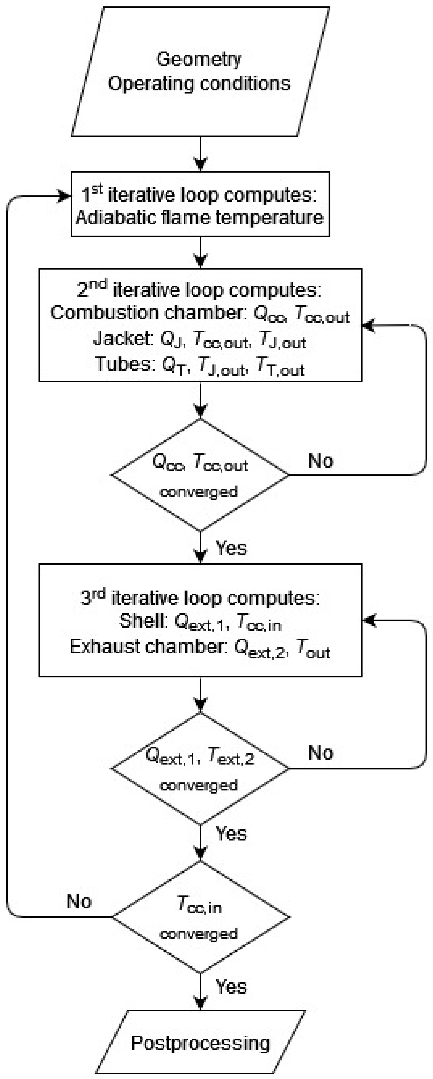
Figure 5 presents the flowchart for the model implemented in the present study.
The equations that describe the heat transfer and the conservation of mass and energy are solved iteratively, starting from the input variables and initial guesses for all unknown variables. Three iteration loops were implemented to solve the system of equations and determine the heat transfer rates and temperatures. The main loop updates all the fluid properties with convergence being obtained when, in two consecutive iterations, the absolute difference in the oven exhaust stream temperature at the end of the preheating, Tcc,in, is less than 1 × 10⁻⁷ and the global energy balance of the entire incinerator, expressed by Equation (31), is verified within 1% of the energy entering the incinerator:
where is the mean specific heat at constant pressure of the stream i over the temperature range from Tref to the temperature of that stream, Ti.
Inside the main loop, two other loops were implemented; one was used to solve the system of mass and energy conservation equations related to the combustion chamber, jacket and tubes, and the other was used to solve the equations that express the mass and energy conservation in the shell and the exhaust chamber. The convergence criteria defined for these two loops were key variables having a variation in consecutive iterations of less than 1 × 10⁻⁷. For the first loop, the variables chosen were the heat loss from the combustion chamber to the jacket, Qcc, and the temperature at the end of the combustion chamber, Tcc,out, and, for the second loop, the heat losses to the exterior through the shell, , and the exhaust chamber, .
The input and output variables used for validation are listed in Table 1.
The input values used in the present study are obtained through measurements in an industrial context. The valves controlling the amount of flue gases that bypass the heat exchanger are fixed at a position of about 50%, meaning that half of the flue gases pass through the heat exchanger while the other half bypasses the heat exchanger. Even though the valve positions are never altered during the incinerator operation, the present study aims to understand how the valve positions affect the system (and not only to validate the model for the actual operating conditions).
The temperatures measured at the end of the combustion chamber and at the exit of the incinerator are used to validate the model presented in this work. These are the only temperatures measured. There are no measurements of the temperatures of the oven exhaust gas after preheating at the inlet of the burner or of the flue gases at the end of the jacket or at the end of the tubes. Developing a model that estimates these variables allows the computation of the heat exchanged between the flue gases and the incoming oven exhaust and the heat lost from the incinerator to the environment. Additionally, the fraction of heat recovery compared to the maximum heat transfer of an infinitely long, countercurrent heat exchanger [37], HR, is calculated by:
The numerator represents the actual energy recovered by the inlet stream, i.e., the increase in sensible heat of the oven gas before combustion, while the denominator represents the maximum energy that would be recoverable if the inlet gases were heated to the temperature of the flue gases prior to entering the heat exchanger. The knowledge of the fraction of energy recovery is useful to express the extent of the improvement in energy efficiency by the use of the preheater [6].
3. Results
3.1. Model Validation
The industrial TRI under study is being monitored, which allows for knowing crucial operation variables of the process and validating the model. Table 2 presents the comparison of the results of the model with measurements obtained in an industrial context on the 18 May 2023 from 10:08 h to 15:38 h, with a sampling period of 15 m (except for the mole fraction of O2 in the flue gases that was obtained from 11:13 h to 11:31 h with a sampling period of 1 s). All the measurements reported in Table 2, except those for the molar fraction of oxygen and VOC mass flow rate, were obtained from instrumentation permanently installed in the industrial facility.
Most of the input variables used for the validation case were simultaneously measured on the 18 May 2023. The exception is the mass flow rate of VOCs taken from an emission report from April 2021. Despite the non-simultaneous nature of these measurements, continuous data collected from February to May 2023 indicate that the incinerator operates in a very stable regime, suggesting that the potential deviation in measurement times may not significantly affect the validation results.
The molar fraction of oxygen at the exit of the incinerator, XO2, is predicted with a relative error of 3.3%. The good agreement between the molar fractions calculated by the model and measured is not surprising since it reflects the overall mass conservation within the system. Possible causes for the deviation between measurements and calculations include the following: (i) the oven exhaust and fuel streams contain small amounts of other substances, which were neglected; (ii) a 100% removal efficiency of VOCs is considered, but small amounts of VOCs may leave the incinerator; and (iii) small amounts of products of incomplete combustion are present in the incinerator exhaust stream, but combustion is considered complete.
On the other hand, the model overestimates the temperatures at the end of the combustion chamber and at the outlet of the incinerator by around 2.1% and 9.0%, respectively. Since (i) the mathematical model is relatively simple, (ii) accurate measurements of gas temperature can be difficult [38,39] and (iii) the measurements were obtained in an industrial environment and not in a controlled laboratory experiment, these deviations are considered low and the model adequate to simulate the operation of the thermal recuperative incinerator under study.
With the results of the model presented in this work, and under the operating conditions listed in Table 2, the estimated fraction of heat recovery achieved by the recuperative heat exchanger integrated into the VOC incinerator is 21%. This is lower than the typical values reported in the literature (40–70%) [1,6,40]. Because of the preheating of the incoming waste stream, auxiliary fuel can be saved. It is known that the heat recovery achieved in TRIs is not as efficient as in other types of incinerators [1], but in the industrial facility where the TRI under consideration is located, incinerator exhaust energy is recovered to heat the air that enters the paint shop oven and the bath used to prepare the automobile chassis to be coated, so the waste heat from the incinerator is recovered downstream the incinerator for process heating.
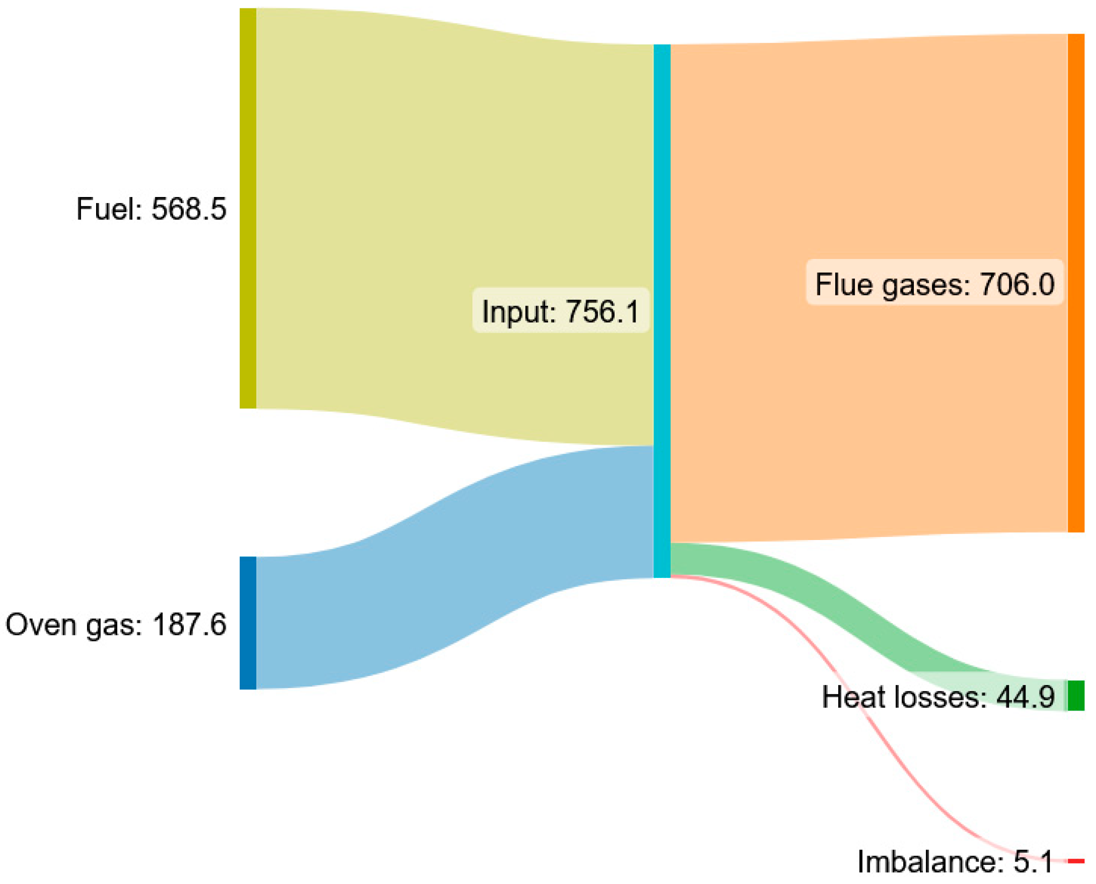
Figure 6 presents the overall energy balance of the incinerator for the model results obtained with the conditions shown in Table 2. The fuel is responsible for most of the energy input to the furnace (75%), while the sensible heat above the datum of the premixed oven exhaust stream accounts for the rest of the energy input. Most of this input energy leaves the incinerator with the flue gases, while 6% is lost to the environment. Sorrels et al. [6] consider that the losses are 10% of the total energy input to the incinerator, a value higher than the calculated by the present model. However, Sorrels et al. [6] consider TRIs where all the flue gases pass through the preheater, while in the present calculations, only half of the flue gases do, while the rest is directly sent to the incinerator exhaust. If more flue gases pass through the heat exchanger, the heat losses to the environment will only be slightly higher, as reported in the Section 3.2.
3.2. Influence of the Varying Level of Heat Recovery
The following results were obtained for the operating conditions reported in Table 2, except for α, which was varied from 0.1 to 0.9. The results are presented as a function of the percentage of the flue gases that bypass the heat exchanger, α × 100, and contribute to understanding the influence of the level of heat recovery from the flue gases to the incoming waste stream on the operation of TRIs.
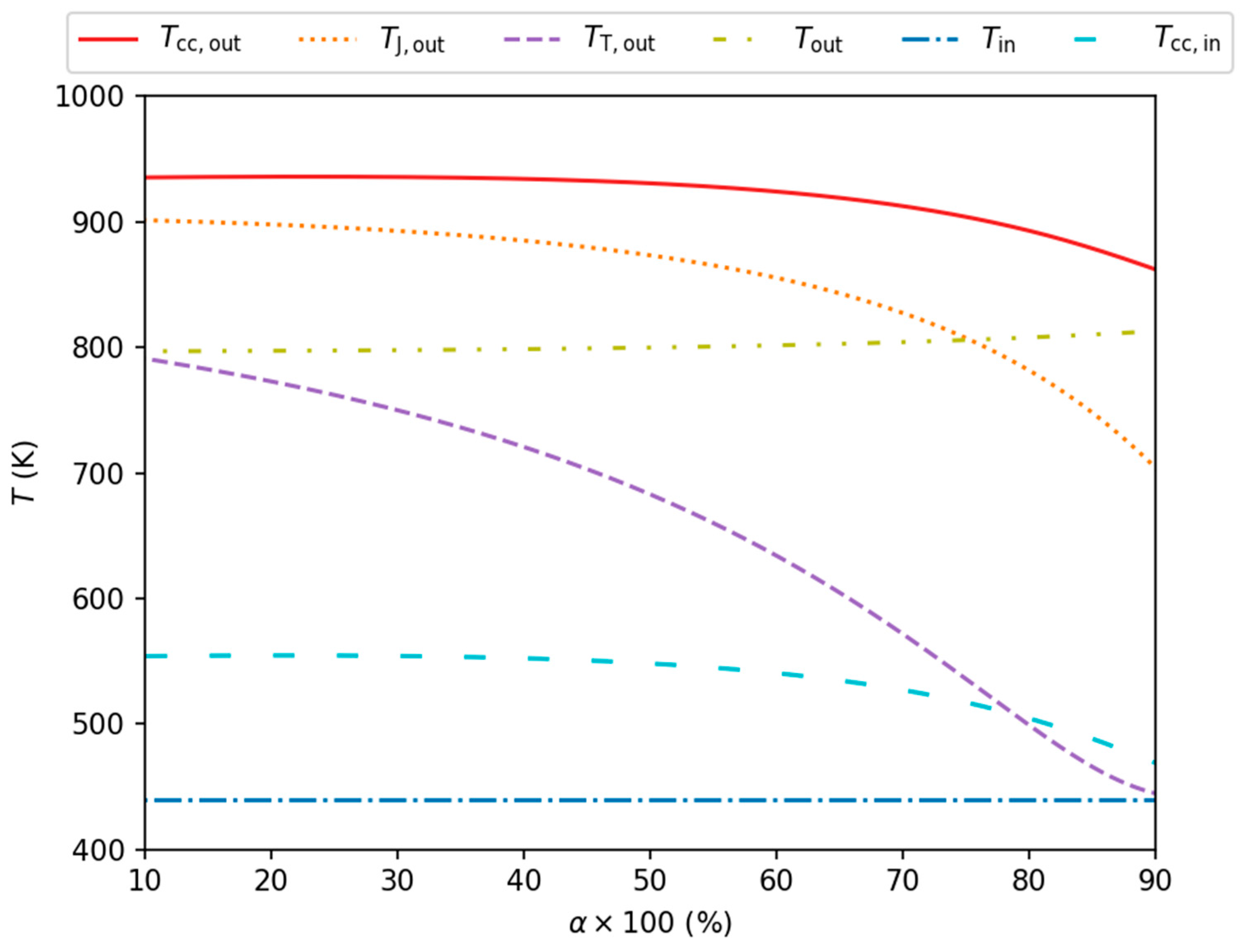
Figure 7 presents the inlet and outlet temperatures of each control volume considered in the model presented in Section 2 as a function of the percentage of the mass flow rate of flue gases that bypass the heat exchanger (see Figure 3).
The dependence of the temperature of the oven exhaust stream after preheating, Tcc,in, on the percentage of flow that bypasses the heat exchanger provides the background to understand the behavior of the TRI. For the largest percentage of flow bypassing the heat exchanger, the heat recovery from the incinerator flue gases to the incoming oven exhaust stream is at its minimum and so is Tcc,in. In fact, for α close to 1, the temperature of the oven exhaust stream at the entrance of the combustion chamber is lower than that at the entrance of the incinerator, Tin, because of the heat losses to the environment from the oven exhaust gases that flow through the shell. Since operating the incinerator in this regime does not make sense, these results are not shown in Figure 7. On the other extreme, the maximum preheating occurs for α equal to around 21%, where the temperature of the oven exhaust stream after preheating is at the maximum. Tcc,in varies very little with α when most of the incinerator exhaust stream flows through the heat exchanger (up to α around 0.5 the Tcc,in are within 1%). From this point on, as more fluid bypasses the heat exchanger, the preheating drops at a higher rate with α.
Figure 7 reveals that the temperature at the end of the combustion chamber, Tcc,out, also does not change much with the increase in the percentage of the flue gases that bypass the heat exchanger for α up to around 0.5 (up to α ≈ 0.36, the values of Tcc,out are within 0.1% of the maximum temperature at the end of the combustion chamber, obtained for an α similar to that where the maximum preheating occurs, while up to α ≈ 0.49, they are within 0.5% of the maximum). As more fluid bypasses the heat exchanger, the temperature at the end of the combustion chamber drops at a higher rate with α. For α equal to 0.5, 0.57, 0.75 and 0.9, Tcc,out is, respectively, 0.6%, 1.0%, 3.4% and 7.9% lower than the maximum at the end of the combustion chamber.
The temperatures of the flue gases at the end of the jacket, TJ,out, and tubes, TT,out, decrease with an increase in the percentage of flue gases that bypass the heat exchanger. They are the temperatures most influenced by the heat recovery level, with the temperature at the end of the jacket and the end of the tubes decreasing, respectively, 22% and 45% when α varies from 10% to 90%. With a distinct behavior, the temperature at the end of the incinerator, Tout, increases with α; however, this temperature remains relatively constant, with a maximum difference below 2% for the entire range of α analyzed. For the smallest , when 90% of the flue gases pass through the heat exchanger, Tout is close to the temperature of the flue gases after passing through the heat exchanger, TT,out, while when 90% of the flue gases bypass the heat exchanger, Tout is closer to the temperature at the end of the combustion chamber, Tcc,out.
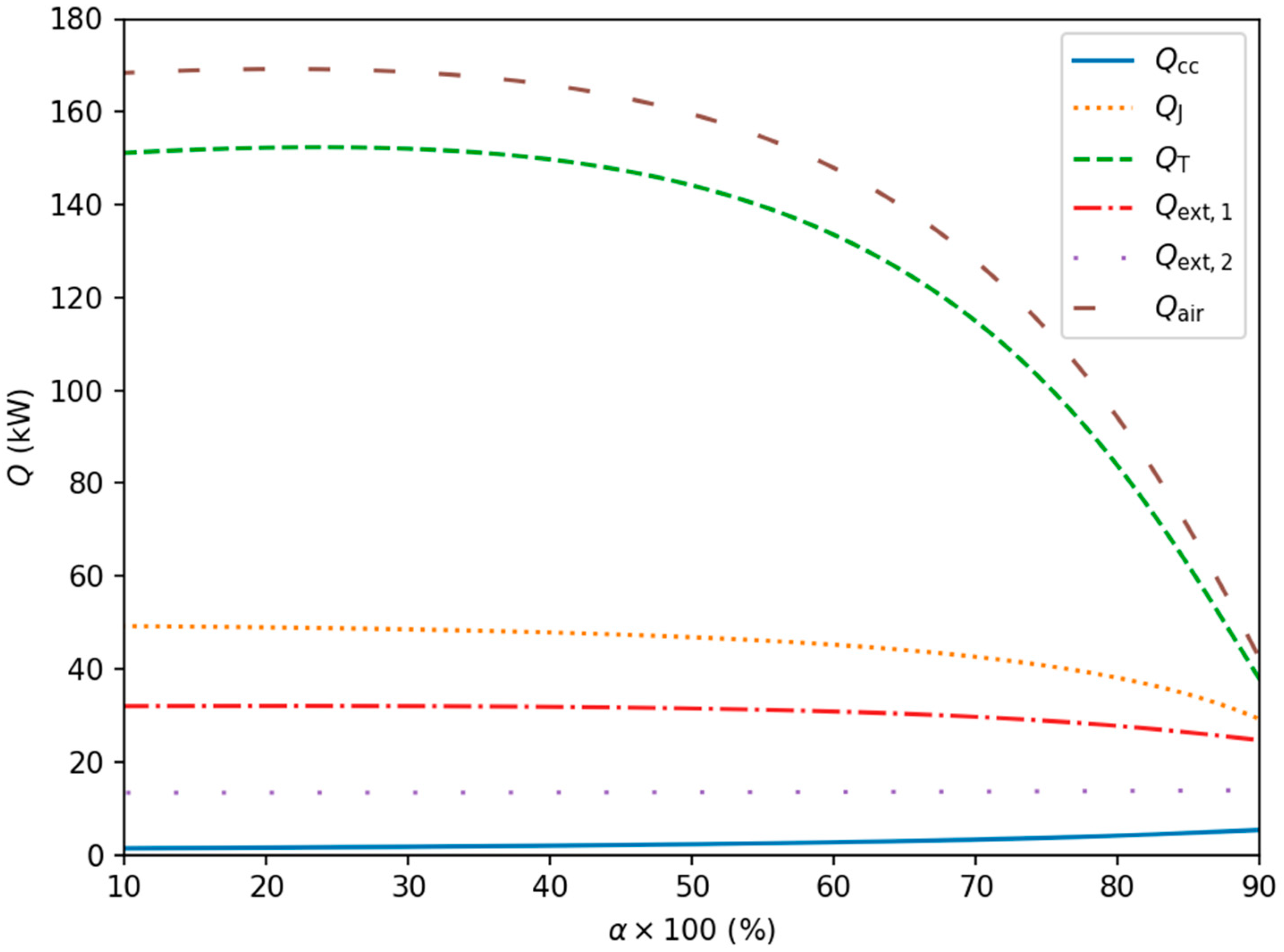
Figure 8 helps to understand how α influences the heat transfer within the preheater. This figure presents the rates of heat transferred to and from the different control volumes considered in the model (see Figure 3). Qair is the net rate of heat transferred to the incoming oven exhaust stream and is equal to QJ + QT − Qext,1.
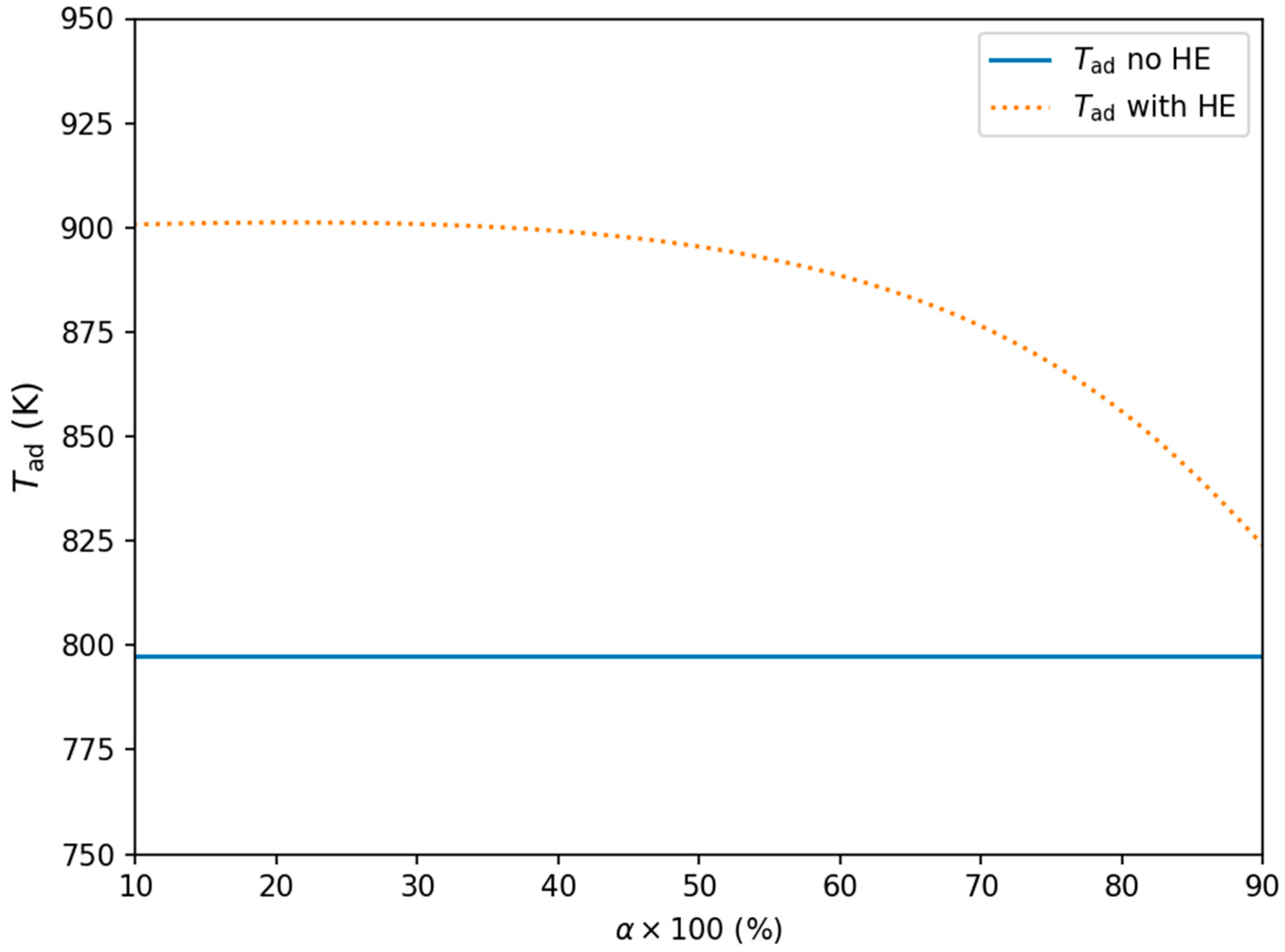
The net rate of heat transferred to the incoming oven exhaust stream, Qair, is the highest when the temperature of the preheated oven exhaust stream is also the highest (α ≈ 0.21). As the percentage of flue gases that bypass the heat exchanger increases, the preheating level first slightly increases and then decreases. The temperature at the end of the combustion chamber, Tcc,out, would also peak at the same bypass percentage if the combustion chamber was adiabatic. To illustrate this, Figure 9 presents, as a function of α, the adiabatic flame temperature, Tad, which is the temperature that the flue gases would reach if the combustion chamber was adiabatic. However, the maximum Tcc,out occurs at a slightly different α because of the heat lost by the combustion chamber, Qcc. The difference is not large, though, because this heat loss is small, increasing most significantly with the amount of flue gases that bypass the preheater for α above around 0.55.
Figure 8 shows that, according to the model developed in this study, the contributions of the jacket and the tubes to preheating the incoming waste stream have different behaviors and levels. The heat lost by the jacket to the shell decreases monotonically with α, while that of the tubes has a maximum at α ≈ 0.24. At this point, the contribution of the tubes is more than three times higher than that of the jacket, and, as the percentage of flue gases that bypass the heat exchanger increases, the difference decreases (for the highest α analyzed, the contribution of the jacket to the preheat of the oven exhaust stream is around 77% that of the tubes).
For higher percentages of flue gases bypassing the heat exchanger, the rate of energy transferred from the jacket to the incoming oven exhaust gases, QJ, is lower than for lower percentages of flue gases bypassing the heat exchanger, but the rate of energy received by the jacket from the combustion chamber, Qcc, is higher. However, for a specific α, the jacket receives less energy from the combustion chamber than it transfers to the shell. As a result, the temperature of the flue gases decreases as they flow through the jacket (the temperature at the end of the jacket, TJ,out, is always lower than at the inlet of the jacket, Tcc,out, Figure 7). This temperature drop increases with α, compromising the next step of the heat exchanger, i.e., the energy transferred from the tubes to the incoming oven exhaust stream.
The total heat losses from the incinerator to the surroundings (Qext,1 + Qext,2) first increase and then decrease with the increase in the percentage of flue gases that bypass the heat exchanger, varying from slightly lower than 6% of the total energy input to the incinerator for the lowest α considered to around 5% for the largest α represented in Figure 8 (the maximum value of the heat losses is 6% of the total energy input). The reason for this behavior is related to the temperature of the incoming waste stream as it flows through the shell that surrounds the incinerator (the lower these temperatures, the lower the heat transfer).
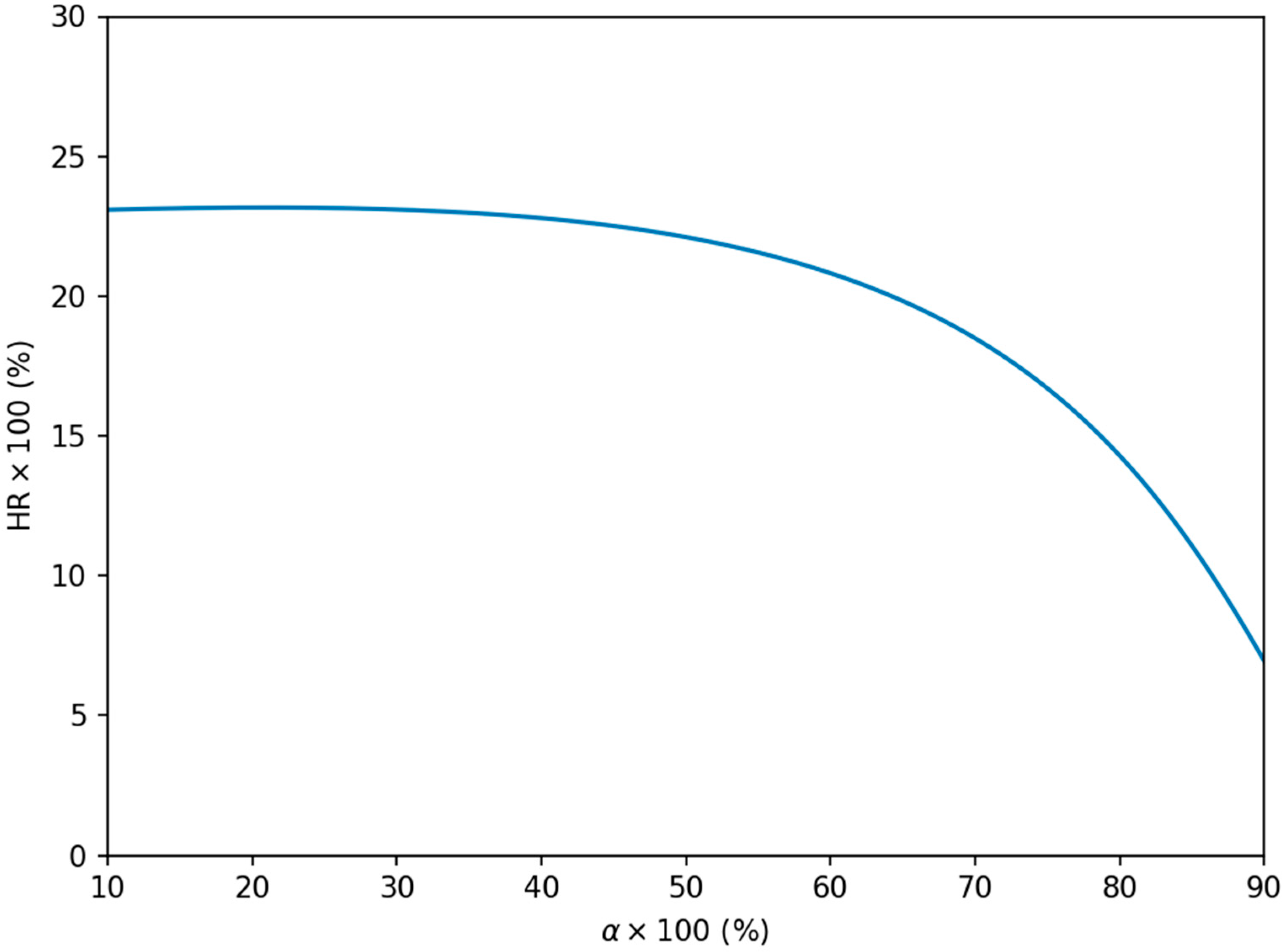
Figure 10 presents the fraction of heat recovery from the flue gases to the incoming waste gases as a function of the percentage of flue gases that bypass the heat exchanger.
The fraction of heat recovery from the flue gases to the incoming waste gases mostly decreases as the fraction of flue gases that bypass the heat exchanger increases, and is in line with the results presented previously.
The fraction of heat recovery achieved by the present model is lower than the typical values reported in the literature (40–70%) [1,6,40]. One of the reasons for the lower HRs might be an underestimation of the heat being transferred from the flue gases to the oven exhaust gases. One of the important simplifications made by the model developed in this study is the heat transfer by convection in the shell side of the heat exchanger. The flow and heat transfer in the shell side of the heat exchanger are quite complex, which poses significant challenges to the estimation of the average shell-side heat transfer coefficient [41]. In reality, a certain number of vertical segmental baffles force the shell-side fluid to flow along an “s-shaped” path, but this was ignored in the present model, which considers that the shell-side fluid flows longitudinally to the tubes. The “s-shaped” flow increases the heat transfer coefficient in the shell-side, which has a higher value in cross-flow [41]. However, despite this simplification, the validation of the present model was very satisfactory.
4. Discussion
Despite their industrial importance and broad use in several industries to control VOC emissions, the number of publications that report analytical or numerical models to simulate thermal recuperative incinerators is very low. The development of such models is important to ensure compliance with environmental regulations and to enhance the efficiency of TRIs or thermal systems that integrate this type of incinerator. With this in mind, a 0D model of a TRI with an integrated heat exchanger that allows for a varying level of heat recovery was developed. The use of computational fluid dynamics simulations was not considered for the present study due to the large geometrical complexity of the thermal recuperative incinerator. Instead, the model developed is based on steady, integral mass and energy conservation equations and equations that account for the heat transfer by conduction, convection and radiation.
The industrial thermal recuperative incinerator modeled in this work is being monitored, which makes it possible to know crucial operation measurements of the process and helps understand how reasonable the model is. Even though there is the possibility of changing the mass flow rate of flue gases that pass through the heat exchanger, the equipment operators never change the percentage of flue gases that bypass the heat exchanger. It is fixed at around 50%, which means that the flow that goes directly to the incinerator exhaust is around 50%. The deviations between measurement values and model results for this percentage of bypass are considered low in light of the industrial conditions in which the data were measured and the model-imposed simplifications. With this model validation, the results of the model presented in this work are expected to support the understanding and optimization of the operation of VOC thermal recuperative incinerators.
The heat recovery system provided by the heat exchanger integrated in the thermal incinerator studied is extremely important to decrease additional fuel consumption. As the percentage of flow that bypasses the heat exchanger increases, the system becomes less capable of exchanging energy between the flue gases and the incoming oven exhaust gases and tends to a point where this heat transfer is quite low. A closer analysis shows that the combustion chamber fluid maintains an almost constant heat capacity when the percentage of flow that bypasses the heat exchanger is varied, but its capability to exchange energy with the jacket system decreases. For the inlet conditions simulated in this study, the temperature at the end of the combustion chamber remains quite constant for bypass percentages of up to around 50~55%. Choosing a lower bypass percentage seems to have little implication on the temperature at the exit of the combustion chamber, suggesting that it would have a minor effect on the VOC elimination capabilities of the TRI studied. However, it would increase the pressure drop in the incinerator and consequently its power requirements. The simulations presented in this work seem to corroborate the percentage of bypass that is currently set in the equipment, which has very stable operating conditions.
5. Conclusions
This study presents a novel 0D model to predict the performance of a thermal recuperative incinerator with an integrated, complex preheater that allows for variable heat recovery. The model is based on the integral form of the equations that express the conservation of mass and energy, the fundamental equations of heat transfer and the -NTU method. Despite its relative simplicity, the model accurately reproduces instrumentation data obtained in an industrial context with a maximum deviation of around 9%. The adaptable structure of this thermodynamics and heat transfer/based model positions it as a versatile tool, applicable to simulate various designs of thermal recuperative incinerators with necessary adjustments. This makes it a valuable asset for evaluating and optimizing the operation of both thermal recuperative incinerators and thermal systems that incorporate them. Even though the incinerator simulated in this work has valves that allow for variable heat recovery, the valve positions are never altered during the incinerator operation. To find out how the performance of the TRI is affected by these valve positions, simulations of the TRI with different valve positions were carried out. The present work shows for, an α of 0.5, that the TRI is able to regenerate 22% of the energy, reducing the fuel consumption. For the operating conditions studied and α ranging from 0.1 to 0.9, the temperatures, after preheating, at the end of the combustion chamber and at the exit of the incinerator, vary, respectively, from 280 °C to 196 °C, 661 °C to 589 °C and 524 °C to 540 °C.
Author Contributions
Conceptualization, F.Z. and I.M.; methodology, F.Z., I.M. and P.C.; software, F.Z.; validation, F.Z., I.M., P.C. and R.P.L.; formal analysis, F.Z. and I.M.; investigation, F.Z., I.M. and R.P.L.; resources, P.C. and R.P.L.; data curation, F.Z.; writing—original draft preparation, F.Z. and I.M.; writing—review and editing, F.Z., I.M., P.C. and R.P.L.; visualization, F.Z.; supervision, I.M.; project administration, I.M., P.C. and R.P.L.; funding acquisition, I.M., P.C. and R.P.L. All authors have read and agreed to the published version of the manuscript.
Funding
Francisco Zdanowski would like to thank the grant conceded by Fundação para a Ciência e a Tecnologia (reference number 2021.04655.BD). This research was funded by Project “MOSIPO”, Project Grant No. POCI-01–0247-FEDER-072621. The work was supported by Fundação para a Ciência e a Tecnologia, through IDMEC, under LAETA [project UIDB/50022/2020]. Paulo Canhoto acknowledges the support of Fundação para a Ciência e a Tecnologia, I.P., through the ICT- Institute of Earth Sciences, projects UIDB/04683/2020 and UIDP/04683/2020.
Data Availability Statement
Restrictions apply to the availability of these data. Instrumentation data was obtained from CCEnergia and are available from the authors with the permission of CCEnergia.
Acknowledgments
The authors would like to thank Flávio Pécurto, who contributed to the development of the geometrical model, and João Gonçalves, who contributed to the industrial data collection.
Conflicts of Interest
The authors declare no conflicts of interest. The funders had no role in the design of the study; in the collection, analyses, or interpretation of data; in the writing of the manuscript; or in the decision to publish the results.
References
- Whitall, K.L. Air Pollution Control in the Finishing Industry. Met. Finish. 1999, 97, 409–419. [Google Scholar] [CrossRef]
- Salvador, S.; Commandré, J.-M.; Kara, Y. Thermal Recuperative Incineration of VOCs: CFD Modelling and Experimental Validation. Appl. Therm. Eng. 2006, 26, 2355–2366. [Google Scholar] [CrossRef]
- Granadero, D.; Garcia-Muñoz, A.; Adam, R.; Omil, F.; Feijoo, G. Evaluation of Abatement Options to Reduce Formaldehyde Emissions in Vehicle Assembly Paint Shops Using the Life Cycle Methodology. Clean. Environ. Syst. 2023, 11, 100139. [Google Scholar] [CrossRef]
- Giampieri, A.; Ling-Chin, J.; Ma, Z.; Smallbone, A.; Roskilly, A.P. A Review of the Current Automotive Manufacturing Practice from an Energy Perspective. Appl. Energy 2020, 261, 114074. [Google Scholar] [CrossRef]
- Chronopoulos, G.; Cakmak, G.-E.; Tempany, P.; Klein, G.; Brinkmann, T.; Zerger, B.; Roudier, S. Best Available Techniques (BAT) Reference Document on Surface Treatment Using Organic Solvents Including Preservation of Wood and Wood Products with Chemicals: Industrial Emissions Directive 2010/75/EU (Integrated Pollution Prevention and Control); Publications Office of the European Union: Luxembourg, 2020. [Google Scholar]
- Sorrels, J.L.; Baynham, A.; Randall, D.; Hancy, C. Incinerators and Oxidizers. In EPA Air Pollution Control Cost Manual; United States Environmental Protection Agency: Washington, DC, USA, 2017; pp. 2.1–2.67. [Google Scholar]
- Shah, R.K.; Sekulic, D.P. Fundamentals of Heat Exchanger Design; Wiley and Sons: New York, NY, USA, 2003. [Google Scholar]
- Arsenyeva, O.P.; Tovazhnyansky, L.L.; Kapustenko, P.O.; Khavin, G.L. Optimal Design of Plate-and-Frame Heat Exchangers for Efficient Heat Recovery in Process Industries. Energy 2011, 36, 4588–4598. [Google Scholar] [CrossRef]
- Yang, Z.; Ma, Y.; Zhang, N.; Smith, R. Design Optimization of Shell and Tube Heat Exchangers Sizing with Heat Transfer Enhancement. Comput. Chem. Eng. 2020, 137, 106821. [Google Scholar] [CrossRef]
- Chen, L.-Y.; Adi, V.S.K.; Laxmidewi, R. Shell and Tube Heat Exchanger Flexible Design Strategy for Process Operability. Case Stud. Therm. Eng. 2022, 37, 102163. [Google Scholar] [CrossRef]
- Li, N.; Chen, J.; Cheng, T.; Klemeš, J.J.; Varbanov, P.S.; Wang, Q.; Yang, W.; Liu, X.; Zeng, M. Analysing Thermal-Hydraulic Performance and Energy Efficiency of Shell-and-Tube Heat Exchangers with Longitudinal Flow Based on Experiment and Numerical Simulation. Energy 2020, 202, 117757. [Google Scholar] [CrossRef]
- Arsenyeva, O.; Perevertaylenko, O.; Tovazhnyanskyy, L.; Arsenyev, P.; Kapustenko, P. Experimental Investigation of Thermal and Hydraulic Performance of Panel Plate Heat Exchangers. Therm. Sci. Eng. Prog. 2023, 43, 101984. [Google Scholar] [CrossRef]
- Fetuga, I.A.; Olakoyejo, O.T.; Abolarin, S.M.; Gbegudu, J.K.; Onwuegbusi, A.; Adelaja, A.O. Numerical Analysis of Thermal Performance of Waste Heat Recovery Shell and Tube Heat Exchangers on Counter-Flow with Different Tube Configurations. Alex. Eng. J. 2023, 64, 859–875. [Google Scholar] [CrossRef]
- Kolta, T. Selecting Equipment to Control Air Pollution from Automotive Painting Operations; SAE Technical Paper Series; SAE International: Warrendale, PA, USA, 1992; pp. 1–18. [Google Scholar]
- Zhuo, W.; Zhou, B.; Zhang, Z.; Zhou, H.; Dai, B. Process Modeling and Exergy Analysis for a Typical VOC Thermal Conversion Plant. Energies 2022, 15, 3522. [Google Scholar] [CrossRef]
- Crawmer, J.K.T.; Chen, C.-H.; Richard, B.M.; Pearlman, H.G.; Edwards, T.V.; Ronney, P.D. An Innovative Volatile Organic Compound Incinerator. In Proceedings of the 36th International Conference on Thermal Treatment Technologies & Hazardous Waste Combustors, Houston, TX, USA, 8 March 2017. [Google Scholar]
- Fuligno, L.; Micheli, D.; Poloni, C. An Integrated Approach for Optimal Design of Micro Gas Turbine Combustors. J. Therm. Sci. 2009, 18, 173–184. [Google Scholar] [CrossRef]
- Vézina, G.; Fortier-Topping, H.; Bolduc-Teasdale, F.; Rancourt, D.; Picard, M.; Plante, J.-S.; Brouillette, M.; Fréchette, L. Design and Experimental Validation of a Supersonic Concentric Micro Gas Turbine. J. Turbomach. 2016, 138, 021007. [Google Scholar] [CrossRef]
- Payri, F.; Olmeda, P.; Martín, J.; García, A. A Complete 0D Thermodynamic Predictive Model for Direct Injection Diesel Engines. Appl. Energy 2011, 88, 4632–4641. [Google Scholar] [CrossRef]
- Siccinio, M.; Fable, E.; Lackner, K.; Scarabosio, A.; Wenninger, R.P.; Zohm, H. A 0D Stationary Model for the Evaluation of the Degree of Detachment on the Divertor Plates. Plasma Phys. Control. Fusion 2016, 58, 125011. [Google Scholar] [CrossRef]
- Li, R.C.; Zhu, G.G.; Men, Y. A Two-Zone Reaction-Based Combustion Model for a Spark-Ignition Engine. Int. J. Engine Res. 2021, 22, 109–124. [Google Scholar] [CrossRef]
- Chinnici, A.; Tian, Z.F.; Lim, J.H.; Nathan, G.J.; Dally, B.B. Comparison of System Performance in a Hybrid Solar Receiver Combustor Operating with MILD and Conventional Combustion. Part I: Solar-Only and Combustion-Only Employing Conventional Combustion. Sol. Energy 2017, 147, 489–503. [Google Scholar] [CrossRef]
- Arpino, F.; Cortellessa, G.; Canale, L.; Dell’Isola, M.; Ficco, G.; Moretti, L.; Zuena, F.; Rinaldi, F. A 0D-3D Approach for Numerical Analysis of Waste to Energy Plants: A Case Study. J. Phys. Conf. Ser. 2021, 1868, 012023. [Google Scholar] [CrossRef]
- Mohammadkhani, F.; Yari, M. A 0D Model for Diesel Engine Simulation and Employing a Transcritical Dual Loop Organic Rankine Cycle (ORC) for Waste Heat Recovery from Its Exhaust and Coolant: Thermodynamic and Economic Analysis. Appl. Therm. Eng. 2019, 150, 329–347. [Google Scholar] [CrossRef]
- Moran, M.J.; Shapiro, H.N.; Boettner, D.D.; Bailey, M.B. Fundamentals of Engineering Thermodynamics, 8th ed.; John Wiley & Sons Inc.: Hoboken, NJ, USA, 2014; ISBN 1-118-41293-1. [Google Scholar]
- Bergman, T.L.; Incropera, F.P.; Lavine, A.S.; Dewitt, D.P. Fundamentals of Heat and Mass Transfer, 7th ed.; John Wiley & Sons: Hoboken, NJ, USA, 2011. [Google Scholar]
- Švantner, M.; Honnerová, P.; Veselý, Z. The Influence of Furnace Wall Emissivity on Steel Charge Heating. Infrared Phys. Technol. 2016, 74, 63–71. [Google Scholar] [CrossRef]
- Kays, W.M.; London, A.L. Compact Heat Exchangers, 2nd ed.; McGraw-Hill Book Company: New York, NY, USA, 1964. [Google Scholar]
- White, F.M. Fluid Mechanics, 8th ed.; McGraw-Hill: New York, NY, USA, 2017. [Google Scholar]
- Gnielinski, V. Neue Gleichungen für den Wärme-und den Stoffübergang in turbulent durchströmten Rohren und Kanälen. Forsch. Im Ingenieurwesen A 1975, 41, 8–16. [Google Scholar] [CrossRef]
- Gnielinski, V. On Heat Transfer in Tubes. Int. J. Heat Mass Transf. 2013, 63, 134–140. [Google Scholar] [CrossRef]
- Gnielinski, V. Heat Transfer Coefficients for Turbulent Flow in Concentric Annular Ducts. Heat Transf. Eng. 2009, 30, 431–436. [Google Scholar] [CrossRef]
- Gnielinski, V. Turbulent Heat Transfer in Annular Spaces—A New Comprehensive Correlation. Heat Transf. Eng. 2015, 36, 787–789. [Google Scholar] [CrossRef]
- Kim, W.K.; Martin, H.; Gnielinski, V. Pressure Drop and Heat Transfer in Shell-and-Tube Heat Exchangers without Baffles Part I. The Graetz-Nusselt Problem in a Cylindrical Shell Containing a Bundle of Seven Tubes. Chem. Eng. Process. 1993, 32, 99–110. [Google Scholar] [CrossRef]
- Gaddis, E.S.; Gnielinski, V. Pressure Drop on the Shell Side of Shell-and-Tube Heat Exchangers with Segmental Baffles. Chem. Eng. Process. 1997, 36, 149–159. [Google Scholar] [CrossRef]
- Turns, S.R. An Introduction to Combustion. In Concepts and Applications, 3rd ed.; McGraw-Hill: New York, NY, USA, 2013. [Google Scholar]
- van der Vaart, D.R.; Marchand, E.G.; Bagely-Pride, A. Thermal and Catalytic Incineration of Volatile Organic Compounds. Crit. Rev. Environ. Sci. Technol. 1994, 24, 203–236. [Google Scholar] [CrossRef]
- Trinks, W.; Mawhinney, M.H.; Shannon, R.A.; Reed, R.J.; Garvey, J.R. Industrial Furnaces, 6th ed.; John Wiley & Sons: New Jersey, NJ, USA, 2004. [Google Scholar]
- Mullinger, P.; Jenkins, B. Industrial and Process Furnaces: Principles, Design and Operation, 2nd ed.; Butterworth-Heinemann: Oxford, UK, 2014; ISBN 978-0-08-099377-5. [Google Scholar]
- EPA Incinerator-Recuperative Type. In Air Pollution Control Technology Fact Sheet; United States Environmental Protection Agency: Washington, DC, USA, 2003; pp. 1–6. Available online: https://www3.epa.gov/ttncatc1/dir1/frecup.pdf (accessed on 20 December 2023).
- Zaversky, F.; Sánchez, M.; Astrain, D. Object-Oriented Modeling for the Transient Response Simulation of Multi-Pass Shell-and-Tube Heat Exchangers as Applied in Active Indirect Thermal Energy Storage Systems for Concentrated Solar Power. Energy 2014, 65, 647–664. [Google Scholar] [CrossRef]
Figure 1.
General principle of a typical thermal recuperative incinerator (in specific applications (not represented in the figure), additional air must also be added to the process exhaust stream [6]).
Figure 1.
General principle of a typical thermal recuperative incinerator (in specific applications (not represented in the figure), additional air must also be added to the process exhaust stream [6]).

Figure 2.
Longitudinal section of the thermal recuperative incinerator.

Figure 3.
Longitudinal half-section sketch of the control volumes considered in the model (not to scale).
Figure 3.
Longitudinal half-section sketch of the control volumes considered in the model (not to scale).

Figure 4.
Cross-section sketch of the incinerator (not to scale).

Figure 5.
Flowchart for the model implementation.

Figure 6.
Overall energy balance of the simulated incinerator (values in kW).

Figure 7.
Inlet and outlet temperatures for each of the five control volumes considered as a function of the percentage of flue gases that bypass the heat exchanger.
Figure 7.
Inlet and outlet temperatures for each of the five control volumes considered as a function of the percentage of flue gases that bypass the heat exchanger.

Figure 8.
Rates of heat transferred to and from each of the five control volumes considered as a function of the percentage of flue gases that bypass the heat exchanger.
Figure 8.
Rates of heat transferred to and from each of the five control volumes considered as a function of the percentage of flue gases that bypass the heat exchanger.

Figure 9.
Adiabatic flame temperature for the cases in the presence or absence of a preheat heat exchanger (HE).
Figure 9.
Adiabatic flame temperature for the cases in the presence or absence of a preheat heat exchanger (HE).

Figure 10.
Fraction of heat recovery as a function of the percentage of flue gases that bypass the heat exchanger.
Figure 10.
Fraction of heat recovery as a function of the percentage of flue gases that bypass the heat exchanger.


Table 1.
Input and output variables used for the validation of the model.
| Input Variables | Output Variables/Measurements |
|---|---|
| , , , Tin, Tf, α | Tcc,out, Tout |
Table 2.
0D Model validation.
| Variables | Measurements | Model Results | Relative Error (%) |
|---|---|---|---|
| Tf (K) | 305.87 ± 1.52 | - | - |
| (kg·s−1) | 1.04 × 10⁻² ± 1.5 × 10⁻⁴ | - | - |
| Tin (K) | 439.65 ± 6.6 × 10⁻¹ | - | - |
| (kg·s−1) | 1.31 ± 1.0 × 10⁻² | - | - |
| (kgC·s−1) | 1.08 × 10⁻³ | - | - |
| α (-) | 0.5 | - | - |
| Tcc,out (K) | 911.45 ± 2.05 | 930.74 | 2.12 |
| Tout (K) | 733.85 ± 1.84 | 799.85 | 8.99 |
| XO2 (%) | 18.2 ± 0.0 | 17.6 | 3.3 |
Disclaimer/Publisher’s Note: The statements, opinions and data contained in all publications are solely those of the individual author(s) and contributor(s) and not of MDPI and/or the editor(s). MDPI and/or the editor(s) disclaim responsibility for any injury to people or property resulting from any ideas, methods, instructions or products referred to in the content. |
© 2023 by the authors. Licensee MDPI, Basel, Switzerland. This article is an open access article distributed under the terms and conditions of the Creative Commons Attribution (CC BY) license (https://creativecommons.org/licenses/by/4.0/).
Share and Cite
MDPI and ACS Style
Zdanowski, F.; Malico, I.; Canhoto, P.; Lima, R.P. Simulation of a Thermal Recuperative Incinerator of VOCs with a Special Focus on the Heat Exchanger. Math. Comput. Appl. 2024, 29, 1. https://doi.org/10.3390/mca29010001
AMA Style
Zdanowski F, Malico I, Canhoto P, Lima RP. Simulation of a Thermal Recuperative Incinerator of VOCs with a Special Focus on the Heat Exchanger. Mathematical and Computational Applications. 2024; 29(1):1. https://doi.org/10.3390/mca29010001
Chicago/Turabian StyleZdanowski, Francisco, Isabel Malico, Paulo Canhoto, and Rui Pedro Lima. 2024. "Simulation of a Thermal Recuperative Incinerator of VOCs with a Special Focus on the Heat Exchanger" Mathematical and Computational Applications 29, no. 1: 1. https://doi.org/10.3390/mca29010001