Article

Repair of Small-Area Delamination in Carbon Fiber-Reinforced Polymer through Small Drilled Hole and Carbon Nanotubes-Reinforced Resin Pre-Coating Technique

Department of Mechanical Engineering, University of Western Australia, Perth, WA 6009, Australia
*
Author to whom correspondence should be addressed.
Inorganics 2023, 11(12), 454; https://doi.org/10.3390/inorganics11120454
Submission received: 22 October 2023 / Revised: 13 November 2023 / Accepted: 21 November 2023 / Published: 24 November 2023
(This article belongs to the Special Issue Carbon Nanomaterials for Advanced Technology)

Abstract

:
This study explores the potential for repairing small, isolated delamination areas in carbon fiber-reinforced polymer (CFRP), while preserving the integrity of the composite structures. A small drilled hole at the center of the delamination section served as a channel for the epoxy infill of the sharp delamination cracks. The pressureless infill repair was achieved through the capillary action of an acetone-diluted resin pre-coating (RPC) solution (without hardener) with CNT reinforcement, comprising 89 m/m% acetone, 10 m/m% resin, and 1 m/m% CNT. This acetone-rich resin pre-coating (RPC) solution is easily prepared and applied to the drilled hole area. Curing of the CNT-toughened resin infill was induced by filling the small drilled hole with a resin–hardener mixture toughened by CNT/aramid pulp. The effectiveness of the delamination repair was compared for curing periods of two weeks and three months. The flexural strength measurements indicated that a restoration level of 77% was achieved in this study, while the optimum 100% restoration was achieved using the same technique for edge delamination repairs.

Graphical Abstract

1. Introduction

Current repair methods in the composite industry are primarily designed for addressing large-area delamination damage in laminar carbon fiber-reinforced polymer (CFRP) composites. These methods typically involve machining and repairing the damaged area with patches [1,2,3], or scarfs [4,5,6], using adhesive-bonded CFRP configurations, as illustrated in Figure 1a. The effectiveness of scarf and patch-joint repairs has been extensively discussed in the literature [7,8,9,10,11], with various extended applications showing excellent restoration results (e.g., single-sided strap, double-sided strap, stepped lap, and double scarf). Additionally, a resin injection method has been developed, involving the injection of resin into delamination cracks under external pressure, facilitated by drilled holes around the delamination area [12,13,14].
While the aforementioned methods are proven to be effective for the repair of large delamination areas, and involve machining and drilling processes, they may not be suitable for the repair of small isolated delamination areas. This small isolated delamination, if not repaired, can potentially propagate in service, creating unnecessary structural integrity concerns in later years.
Although studies have focused on the impact of drilling or impact processes on composite designs [15,16], delamination is inevitable in service and even in the normal repair process (e.g., micro-edge delamination). Furthermore, the narrow and sharp nature of delamination cracks in CFRP, coupled with the high stiffness of the material, often necessitates the application of pressure to facilitate resin penetration. If the viscous adhesive is unable to penetrate into sharp crack tips, there is a risk of infinite stress concentration persisting within the CFRP structure, as illustrated in Figure 1c.
Figure 1. (a) Large-area delamination in CFRP repaired using scarf, patch, and resin injection method. (b) The CFRP repair methods can potentially trigger further crack propagation or leave unfilled crack tips in the CFRP. (c) Applying either external tensile stress or internal pressure along the directions of the arrow will create the same infinite stress concentration at the delamination crack tip [17], i.e., further delamination may be induced by the internal pressure applied during the repair.
Inorganics 11 00454 g001
It is possible that small-area delamination, only a few millimeters across, may be detected in CFRP composites, as shown in Figure 2a. These areas may be too small to effectively utilize standard scarf or patch-joint repair methods. However, despite their small size, if left unrepaired, these delaminations can propagate and lead to severe structural issues due to the high-stress concentration at the crack tips. Surprisingly, the literature does not extensively cover the repair of small-area delaminations, which presents a significant gap in the current understanding of composite repair techniques. It is worth noting that regular safety inspections, along with the removal of sharp crack tips in small-area delamination, can significantly enhance the reliability of CFRP structures. However, it remains essential to address and repair these small areas of delamination to ensure the long-term structural integrity of the composite.
The primary objective of this study is to develop a repair method for small-area delamination in CFRP composites that cannot be easily handled by existing repair methods designed for large-area delamination. Specifically, the aim is to fill sharp delamination crack tips without applying pressure, inspired by research on maximizing adhesive bond strength. The ideal adhesive bonding scenario is illustrated in Figure 2b, where all the substrate micro-cavities are entirely filled by the adhesive, resulting in optimum bonding conditions [18]. The pressureless resin pre-coating (RPC) method has been developed to achieve these ideal bonding conditions, as illustrated in Figure 2c, given that the RPC method has the potential to extend the technology for repairing sharp delamination cracks in CFRP.
This study verifies the above hypothesis illustrated in Figure 2 that the pressureless repair method using the RPC solution can be adopted for the small-area delamination in the CFRP. A small drilled hole around 2 mm in diameter was introduced at the center of the delamination area, around a few millimeters across. The sharp delamination cracks were then filled through the capillary action of an acetone-rich resin solution (without hardener). Carbon nanotubes (CNT) could be pre-mixed with this RPC solution and infiltrate into the sharp delamination crack tips. The pressureless RPC and RPCCNT techniques have been successfully used for enhanced adhesive bonding between CFRP and various metal substrates [18,19,20]. Furthermore, a recent preliminary study on the repair of edge delamination in CFRP also supported potential applications of the RPC method for composite repairs, and the latest research has achieved 100% restoration in repairing edge delamination [21]. Therefore, the relevant repair results for edge delamination using the same RPCCNT method are compared with those of small-area delamination with small drilled holes. This simple and effective technique can be conveniently applied in a laboratory for small-sized CFRP tests and adopted on-site for large structures with a small delamination zone.

2. Results and Discussion

2.1. Feasibility and Detailed Steps for Small-Area Delamination Repairs

2.1.1. Pressureless Repair of Sharp Delamination Crack Tips Using RPCCNT Suspension

It can be envisaged that even with a drilled hole at the delamination site, complete adhesive filling of sharp delamination crack tips in CFRP is still challenging. The pressureless adhesive repair procedure, as depicted in Figure 3, involves two steps: first, repairing the delamination cracks using an acetone-rich RPC solution with or without carbon nanotubes (CNT) and, second, filling the drilled hole with epoxy adhesive, with or without short or micro-fiber reinforcement. It should be mentioned that the RPC method was first used to penetrate micro-cavities in CFRP and metal substrates to be bonded by adhesives [20].
Figure 3a illustrates the difficulty of filling the sharp delamination cracks using normal viscous epoxy (with hardener) without applying pressure. The high viscosity of a normal epoxy adhesive makes it difficult to fill sharp delamination crack tips without external force. In contrast, Figure 3b,c display the successful repair results from using the acetone-rich RPC solution and RPCCNT suspension, which can penetrate deep into delamination cracks through capillary action. Only normal epoxy adhesive is used in the drilled holes in all three scenarios from (a) to (c). For optimal repair, Figure 3d illustrates the use of a toughened epoxy adhesive reinforced by CNT and aramid pulp (AP) micro-/nano-fibers to fill the drilled hole. The curing of the precoated thin resin layer (without hardener) occurs gradually from the drilled hole edge upon contact with the normal epoxy (with hardener). Depending on the depth of the delamination cracks, the curing time of the resin (no hardener) within the delamination cracks may differ. The study tested curing periods of two weeks and three months, although it is noted that the resin may not actually take that long to fully cure. The prolonged three-month term was chosen to ensure complete healing of the adhesive and to maximize the effectiveness of the repairs.
To understand the behavior of small fibers treated with RPC, two trials were conducted. In the first trial, 15 m/m% of CNT were directly mixed with West System epoxy adhesive (resin to hardener ratio of 5:1) by mechanical stirring for 1 min. In the second trial, 15 m/m% of CNT was mixed with the RPC solution, first by mechanical stirring for 1 min, after which the same proportion of hardener was added to the RPCCNT suspension once the acetone had completely evaporated. Both mixes were poured into a Teflon mold with standard dumbbell shapes and allowed to cure. The specimens were then subjected to extension testing, and the structural details of the failed surfaces were examined using scanning electron microscopy (SEM). Figure 4 clearly demonstrates that CNT fibers in the adhesive are tangled and distributed unevenly, resulting in relatively slippery fracture surfaces. In contrast, the CNT dispersed in the RPC solution are well distributed, leading to rough surfaces with disentangled fibers. Therefore, the perfectly dispersed RPCCNT suspension used in CFRP delamination repair could yield better restoration outcomes.
The RPC solution contains approximately 90 m/m% of acetone and 10 m/m% of resin (without hardener), while the RPCCNT suspension consists of 89 m/m% acetone, 10 m/m% resin, and 1 m/m% CNT, with the CNTs well dispersed within the suspension. The acetone-rich solution/suspension can effectively penetrate deep into the sharp delamination cracks without the need for pressure. However, it is important to allocate sufficient time (approximately one hour in a fume hood) for the acetone to evaporate from the narrow delamination cracks, before filling the drilled hole with normal epoxy (with hardener). Recent research [22] has shown that after the complete evaporation of acetone, the final epoxy adhesive properties are not affected, ensuring effective repair.
The necessity of pressureless repair, as illustrated in Figure 3, is explained by the stress concentrations at the crack tips depicted in Figure 1—Linear Elastic Fracture Mechanics (LEFM) [23,24]. Firstly, the delamination cracks are very narrow due to the high stiffness of the CFRP, around 200 GPa. Secondly, without applying any pressure, the viscous epoxy adhesive cannot penetrate deep into those sharp delamination cracks. It is important to note that both far-field tensile stress and internal pressure can generate the same positive stress intensity factor K, as indicated in previous research [15], potentially leading to further delamination growth. Therefore, in contrast to traditional repair methods outlined in the existing literature, the proposed pressureless RPCCNT technique utilizes the capillary action of the RPC solution to effectively repair sharp delamination cracks.
It should be emphasized that the above LEFM analysis is limited to elastic and iso-tropic materials, thus it is used here for qualitative analysis. Recently, the critical strain energy release rate model [25,26,27] and the cohesive fracture zone model [28,29] were developed for better explanation of the fracture behavior of composite materials.

2.1.2. Effects of Small Drilling Hole on Flexural Strength of CFRP Specimens

The 2 mm small hole in Figure 5 was created using an Ozito 500 W drill. The drill bit used was a tungsten carbide twist drill, with a point angle of 140° and a helix angle of 35°, and a drill diameter of 2 mm. During the drilling tests, all the CFRP specimens were securely clamped on a wooden base. The drill speed was set at 1500 RPM, with a moving speed of 10 mm/min. Subsequently, all the drilled specimens underwent ultrasonic cleaning in a 97% alcohol base for 30 min to remove all the CFRP debris.
Composite machining and drilling can lead to edge delamination, as discussed in references [30,31,32,33,34], and the comparison between Figure 5a,b indeed indicate that the drilled hole edge has been widened. The effects of the drilled holes were measured before the composite repair, and the results are presented in Figure 6. The average flexural strength of the “as-received” specimens from the three-point bend (3-P-B) tests is approximately 1180 MPa. These as-received specimens were prepared from commercial CFRP (Carbonwiz Technology Limited, Shenzhen, China), consisting of two plies of unidirectional prepreg for the inner layers and nine plies of 3K plain weaved prepreg for the outer layers.
The impact of the small drilled hole is evident in the flexural strength of the CFRP specimens without delamination damage, with a reduction from 1180 MPa to 582 MPa. However, for the specimens with delamination damage, the reduction is limited, with the strength decreasing from 598 MPa to 563 MPa, representing a reduction of less than 6%. The flexural strength measurements in Figure 6 serve as valuable references for evaluating the effectiveness of the RPCCNT repair method.

2.1.3. Surface Contact Curing of Resin Filled by RPC

The well-studied composite self-healing mechanisms, as illustrated in Figure 7 [35,36], can elucidate how the resin in the delamination cracks, filled by RPC, undergoes curing after repair. In this process, there is no mixing of resin and hardener, and the composite self-repair is completed through a diffusion-like contact curing of the resin and hardener. The delamination repair in this study follows the same principle. However, the curing time period, which may extend for weeks, can vary depending on the length or depth of the delamination cracks. Two different surface contact curing processes, namely (1) hardener ⟶ resin and (2) resin/hardener mix ⟶ resin, have been tested and are depicted in Figure 8 For the sake of convenience and illustrative purposes, a commercially available Selleys Araldite Super Strength Two-Part Epoxy Glue (similar to epoxy resin but with a different type of hardener compared to the Western System adhesive) was used for the experiments.
In the experiments depicted in Figure 8, one group features a drop of hardener placed beside an epoxy resin drop on top of a glass slide, while the other group utilizes a drop of pre-mixed epoxy resin with hardener placed beside an epoxy resin drop. The results show that the epoxy and hardener mixture is more favorable for the contact curing required by the composite repair, as the curing process is faster and more complete for the testing time of 48 h. These simple experiments demonstrate that the composite self-repair mechanisms illustrated in Figure 7 are feasible. Additionally, the design of an adhesive mix repair after RPC treatment is verified to be more favorable for hardener diffusion.

2.2. Results

2.2.1. Delamination Repairs Using Resin Pre-Coating (RPC) Solution and RPCCNT Suspension

Because of the small drilled hole at the center of the delamination area, it will be interesting to check whether normal epoxy adhesive (resin + hardener) can repair sharp delamination cracks without applying any pressure and whether the micro-/nano-fiber toughened epoxy (used to fill the drilled hole) has any effect on the flexural strength of the CFRP plates.
Five specimen groups with different conditions are shown in Figure 9. The first group is for specimens with indentation-induced delamination damage (no repair), and the second group is for specimens with open drilled holes (no repair). Open drilled holes in the remaining three groups in Figure 9a were filled with normal epoxy adhesive (resin + hardener). In Figure 9b, the last three groups were filled with CNT and AP micro-/nano-fiber toughened adhesive.
The introduction of a drilled hole at the center of the delamination resulted in only a minor 6% reduction in the flexural strength, while delamination repairs using normal epoxy or CNT and AP-toughened epoxy showed modest increases of around 10%. In contrast, the RPC method proved to be promising, leading to a substantial 40% improvement in strength, reaching 840 MPa. The most significant enhancement was achieved by RPCCNT with the drilled hole filled by CNT and AP micro-/nano-fiber-toughened epoxy, resulting in an impressive 53% increase in flexural strength, reaching 912 MPa from the initial 598 MPa.
In the study, the last group in Figure 9 featuring CNT was not directly observable in the CFRP specimens. To address this, separate experiments were conducted and presented in Figure 10 For this purpose, two glass slides were stacked with a 12 μm separation and a 6 mm cross-section to simulate similar delamination crack dimensions. The use of acetone, which has ultralow viscosity, allowed the RPC solution to penetrate any crack-like structure easily. The simulation with glass slides aimed to provide insights into the behavior observed in CFRP delamination cracks. It was noted that while viscous epoxy adhesive (resin + hardener) showed limited penetration into the micro-gap between the glass slides, even after 24 h, the RPC solution was able to penetrate the entire micro-gap in just 5 s due to its low viscosity and capillary action, as depicted in Figure 10a,b. The RPCCNT suspension demonstrated a similar rapid penetration in 5 s, as evidenced by the distributed black CNT shown in Figure 10c. The presence of CNT inside delamination cracks could offer a valuable fiber bridging mechanism, enhancing the effectiveness of the pressure repair by the RPC method.

2.2.2. Curing Time Periods Required by RPC and RPCCNT Repair Methods

The contact curing process for the RPC repair method can be time consuming, particularly due to narrow delamination cracks, which are always a few millimeters deep. Consequently, two curing time periods were evaluated in this study: 2 weeks and 3 months after the delamination repair. It is worth noting that the actual complete curing time may not necessarily be as long as 3 months. Figure 11 provides a summary of the flexural strengths observed under various repair conditions. Interestingly, no significant difference was observed between the RPC and RPCCNT repair methods within the first two weeks. However, the advantage of RPCCNT became evident after three months of curing. The results depicted in Figure 11 indicate that the curing time should indeed be longer than 2 weeks. This long-term outcome also confirms the assumption that a longer cure is expected to result in a better improvement, a notion that has been supported by the latest research [21].

2.2.3. CNT and Micro-/Nano-Fiber Toughened Epoxy for the Drilled Hole

The microstructure features of AP micro-/nano-fibers and CNT are depicted in Figure 12a,b. These materials were employed to reinforce the epoxy adhesive used to fill the drilled hole, as illustrated in (c), where the AP fibers are presented at the drilled hole surface, and (d) where CNTs are dispersed into the delamination cracks for structural enhancements. The acetone-rich RPC solution played a crucial role, as it was utilized to wet the CNT and AP for an even dispersion and the removal of any air pockets within the clusters of micro-/nano-fibers. The hardener was added after the evaporation of the acetone. The composite adhesive design consists of 1 m/m% of AP, 0.5 m/m% of CNT, and 98.5 m/m% of adhesive (resin with hardener).
Figure 13 highlights the impact of a drilled hole epoxy filling with and without CNT and AP. All the results were obtained after a 3-month curing period. The most effective repair outcome was observed with the RPCCNT and CNT–AP-toughened epoxy filling. It is important to note that the “as-received” specimens in Figure 13 do not contain drilled holes and delamination damage. Therefore, achieving a “77% restoration” (912/1180 MPa) from the RPCCNT specimens with drilled holes and previous delamination damage represents a positive outcome.
Given the narrow width of the specimen at 20 mm, the 2 mm drilled hole could significantly impact the flexural strength of the structure. Therefore, the same RPCCNT method was performed on specimens with edge delamination, eliminating the need for drilling during the delamination repair. The Instron 5982 universal testing machine from Instron Corp., USA, was used to test the compressive strength, according to ASTM D 3410/D 3410M-03 [37], with a testing rate set to 1 mm/min and an automatic recording every 0.1 s for the load and crosshead displacement. The corresponding repair results for 2 weeks and 3 months are depicted in Figure 14. In the case of edge delamination, a 100% restoration in the compressive strength was achieved, demonstrating the effectiveness of the RPCCNT technique for delamination repair. It is suggested that the repair results in Figure 13 could potentially be further improved to achieve close to 100% recovery, based on the results shown in Figure 14.
It is important to note that this study focused on proving the effectiveness of RPCCNT, hence a specific concentration of CNT was used. Additionally, the extended curing period of three months may not align with practical industrial applications, though it is worth considering that the actual cure time may be shorter. Furthermore, the standard concentrations and ratios used for the filling material in the hole may not be optimal. Future research should explore different CNT concentrations in RPC treatment, determine the actual cure time, and investigate suitable infill materials to achieve optimal restoration in drilled hole repair studies. These considerations can lead to more effective and practical repair techniques.

3. Materials and Methods

There are two major parts in the section: (1) preparation of the CFRP samples, followed by inducing small-area delamination for the repair experiments, and (2) preparation of the resin pre-coating (RPC) solution with and without CNT.
The commercially fabricated CFRP panels (Carbonwiz Technology Limited, China) consisting of two plies of unidirectional prepreg for the inner layers and nine plies of 3K plain weaved prepreg for the outer layers were utilized in this research. All the specimens were trimmed to a size of 100 mm × 20 mm × 2 mm for the repair study, as shown in Figure 15.
The West System adhesives, containing 2,2-bis[p-(2,3-epoxypropoxy)phenyl]- polymers in the epoxy resin and reaction products of triethylenetetramine with phenol and formaldehyde in the hardener (standard resin to hardener ratio is 5:1), were selected in this study to repair the sharp delamination cracks in the CFRP, using the RPC technique described in Section 2. The damaged areas of the CFRP introduced by static load are consistent and reproducible compared with the impact load [38]. Thus, the small-area delamination in the CFRP plate specimen was introduced by a compressive load up to 2450 N, through a spherical indenter with a diameter of around 2 mm. The damaged area at the specimen centre was about 10 by 5 mm, as shown in Figure 15a. Then, the same 2 mm open hole was created at the centre of the delaminated area by a 2 mm drill.
The RPC solution consists of 90 m/m% of acetone and 10 m/m% of resin (without hardener), and the CNT-containing RPC solution (RPCCNT) consists of 89 m/m% of acetone, 10 m/m% of resin, and 1 m/m% of CNT. Simple mechanical stirring with a glass rod is sufficient for acetone-rich solutions. As shown in Figure 15b, two different pre-coating methods were utilized (RPC and RPCCNT treatments) to fill the micro-crack tips. For both methods, the specimens were soaked in these solutions for 1 min, then taken out and placed in a fume hood for one hour to ensure complete acetone evaporation. The RPC and RPCCNT processes were repeated five times.
Finally, the drilled hole was filled with the epoxy adhesive (resin with hardener, 4.5:1) for Method I, and the CNT and micro-/nano-fiber-toughened epoxy adhesive (resin with hardener, 4.5:1) for Method II, as shown in Figure 15c. The mixture for Method II consisted of 1 m/m% of aramid pulp (AP) micro-/nano-fibers, 0.5 m/m% of CNT, and 98.5 m/m% of epoxy. Then, all the repaired specimens were placed in the fume hood for two different curing periods: two weeks and three months. Before flexural testing, all the specimens were placed in a dry oven at 80 °C for 24 h to guarantee that the epoxy adhesives were completely cured.
To compare the effectiveness of the repair techniques adopted in this article, simple three-point bend tests (3-P-B) on the CFRP plates with different repair conditions were performed using an Instron 5982 testing machine, with a 100 KN load cell and at a displacement rate of 1 mm/min. Every specimen condition/group had 10 specimens and the average flexural strength and scatter (maximum and minimum) were calculated and recorded.
Specimens with the delamination damage and drilled hole were scanned at 80 KV and 74 μA using an X-ray micro-computed tomography (X-ray μCT) system (Versa 520, Zeiss, Pleasanton, CA, USA), running the Scot and Scan software (v12.0.8164.19636 Zeiss). The CT images of the overall views and cross-section views (A-A and B-B directions) are shown in Figure 4, where the drilling process seems to have widened the delamination crack openings at the drilled hole edge. Suitable X-ray transmission was achieved using an air beam filter (no filter). A total of 1602 projections were collected over 360°, each with a 5 s exposure. Raw projection data were reconstructed automatically using the XMReconstructor software (v12.0.8164.19636, Zeiss), using the standard 0.7 kernel size recon filter setting. The visualization and analysis of the data generated from the X-ray μCT scans were performed using the Avizo (v.8.1.1, ThermoFisher, Waltham, MA, USA) software, using a customized workflow. The presence of CNT and AP and their distribution inside the delamination cracks were examined with a Verios SEM at 5 kV and 100 pA using a TLD detector. All the specimens were coated with Pt for the SEM observations.

4. Conclusions

The pressureless resin pre-coating (RPC) technique, originally designed for stronger adhesive bonding, was effectively utilized to repair sharp delamination cracks in CFRP in this study. The RPCCNT suspension (RPC solution containing CNT reinforcement) was capable of carrying CNT deep into narrow delamination cracks because of the excellent penetrating behavior of acetone and the capillary action generated by acetone evaporation. As a result, the RPCCNT method achieved a 77% restoration of the flexural strength for small-area internal delamination in this study. With further work and optimization, 100% restoration of the compressive strength may be possible, as proven for edge delamination. These specific findings highlight the effectiveness of the RPCCNT method for repairing delamination cracks in CFRP.
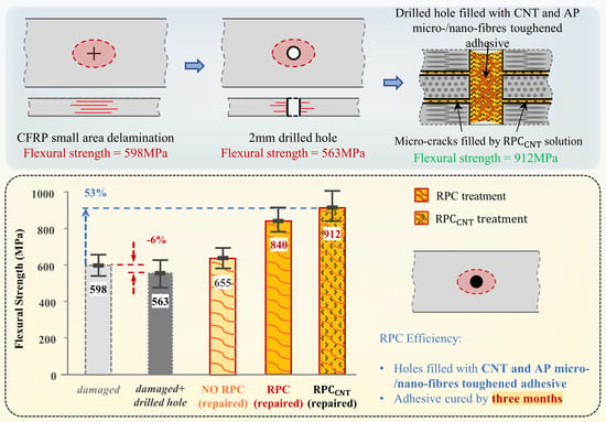
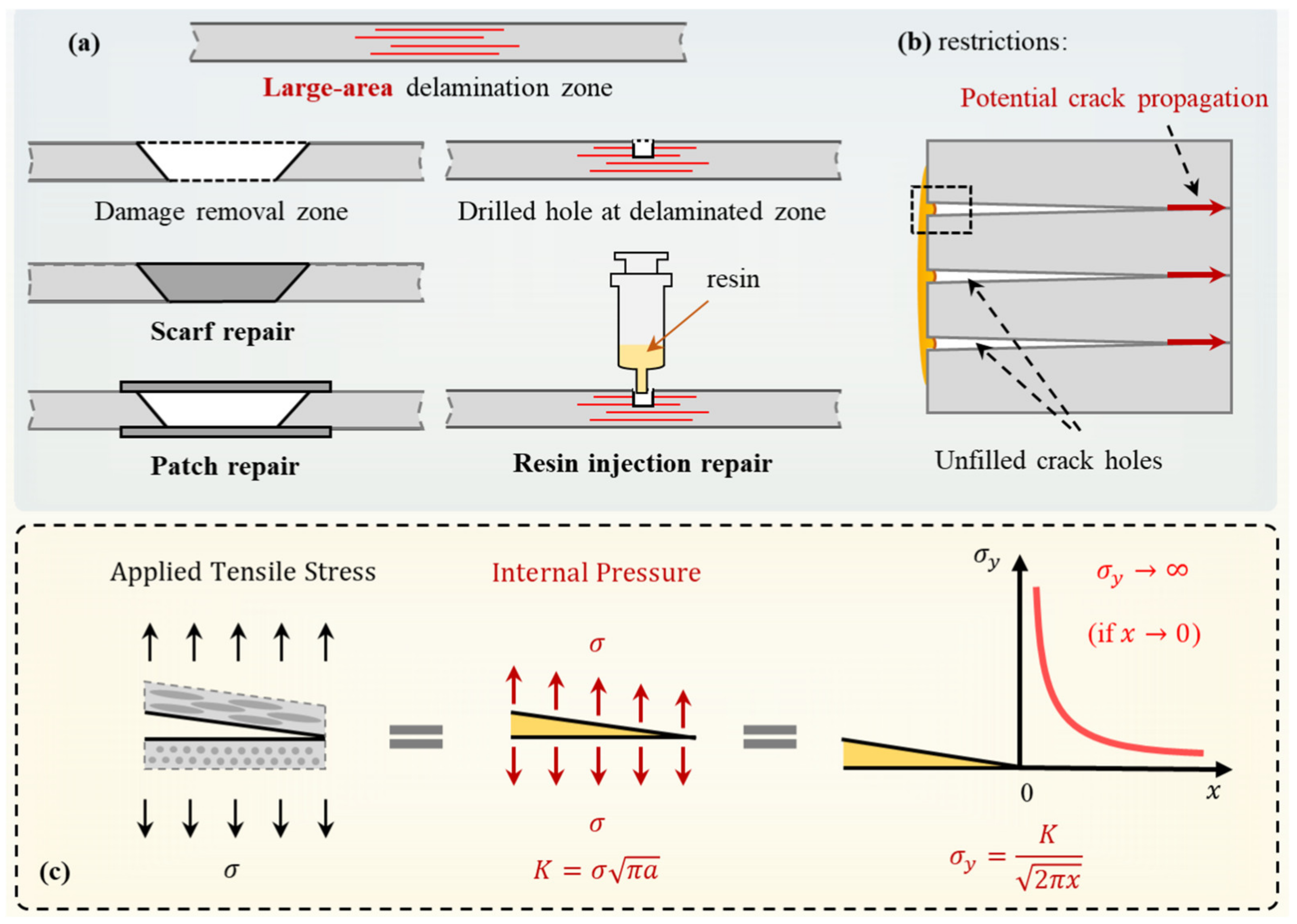
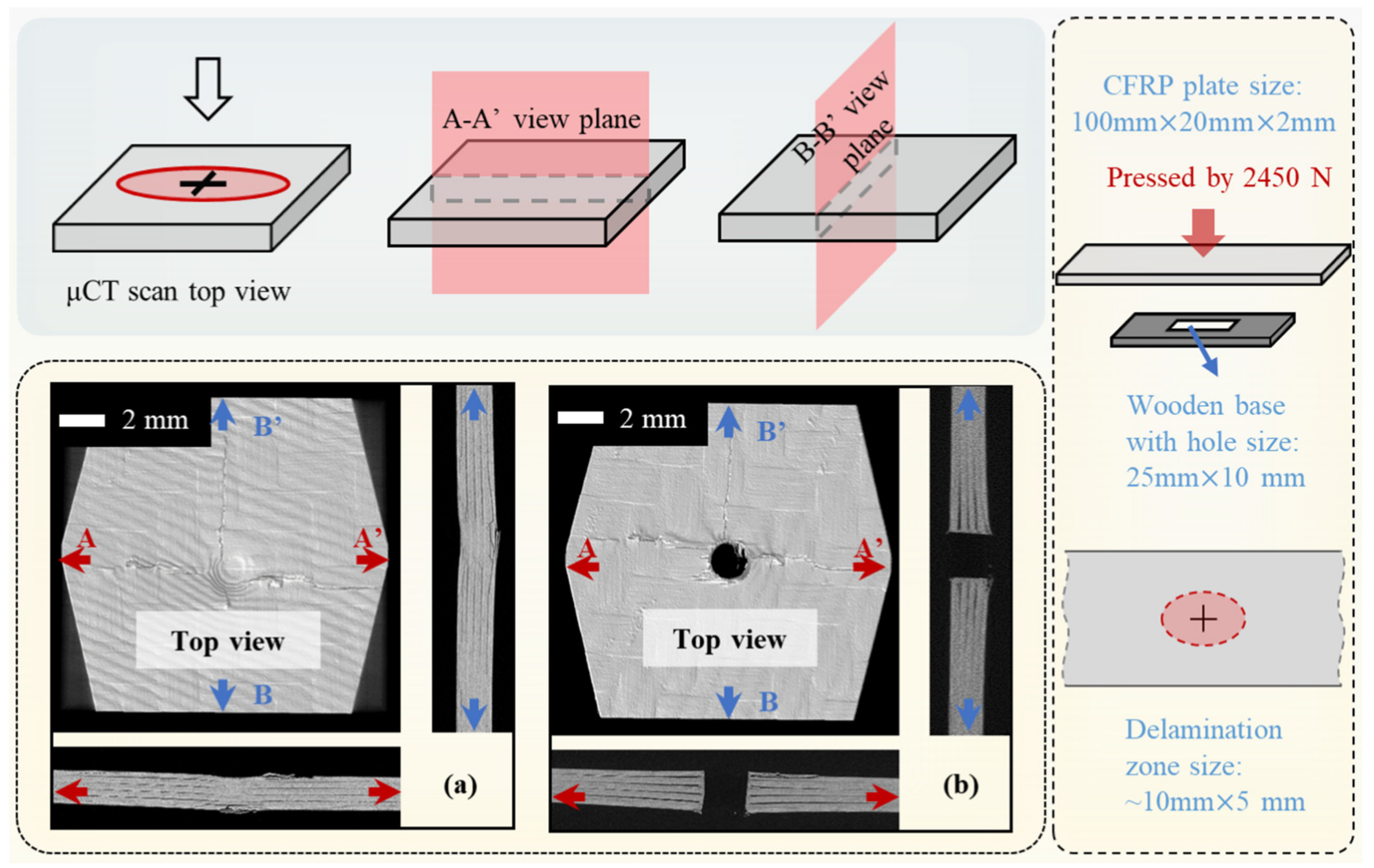
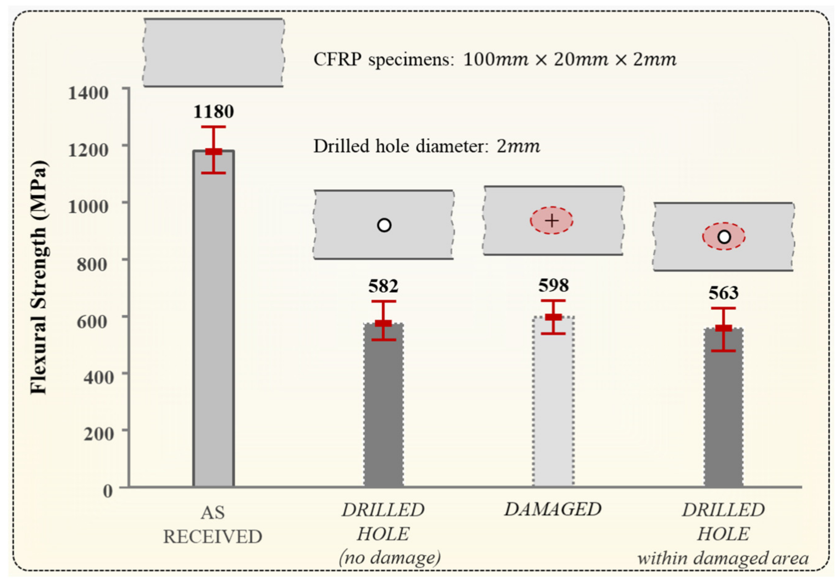
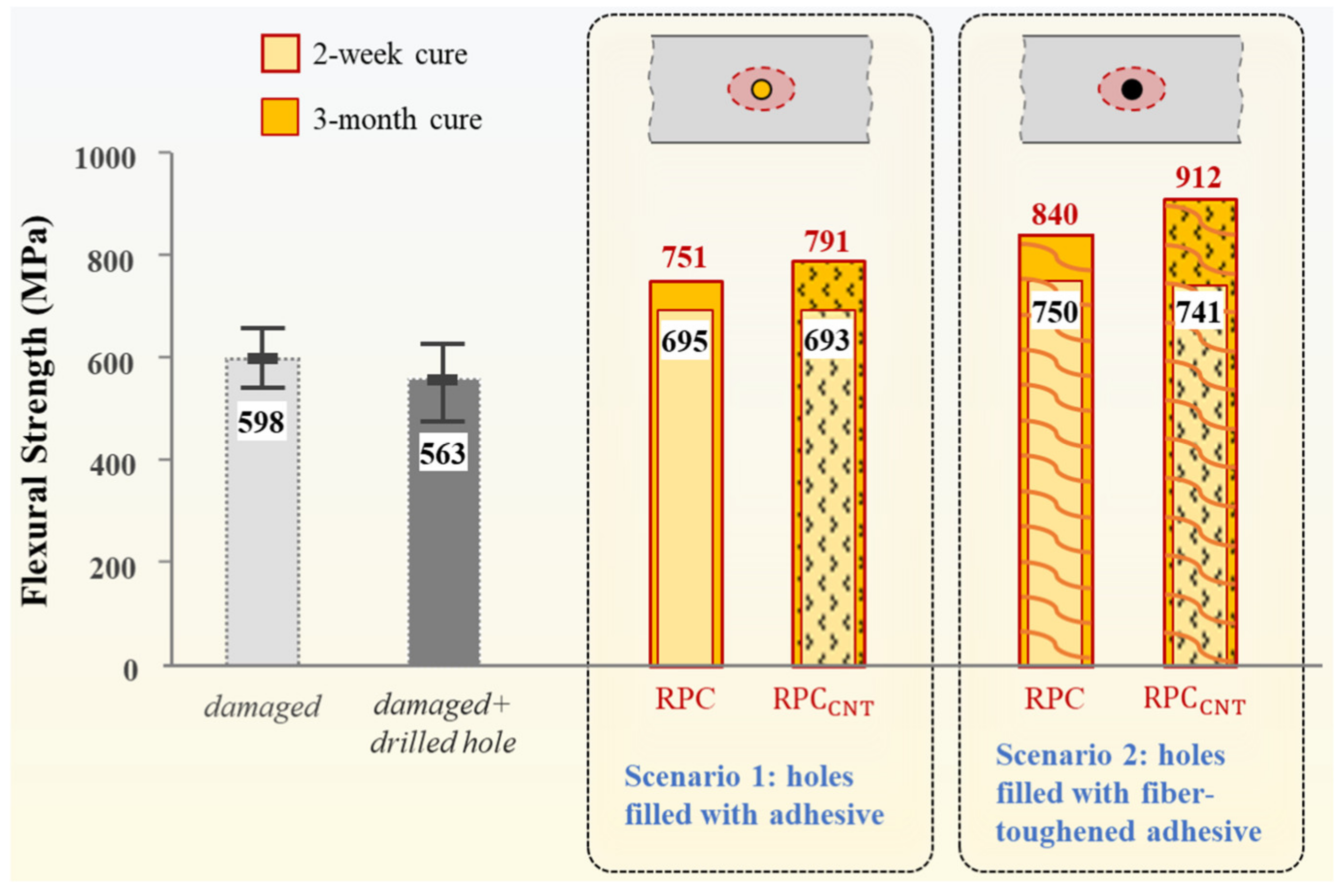
  • The introduction of a small drilled hole (2 mm in diameter) at the center of the delamination zone did not significantly weaken the CFRP specimens (20 mm in width), but it did provide access to the internal delamination cracks required by the RPC method.
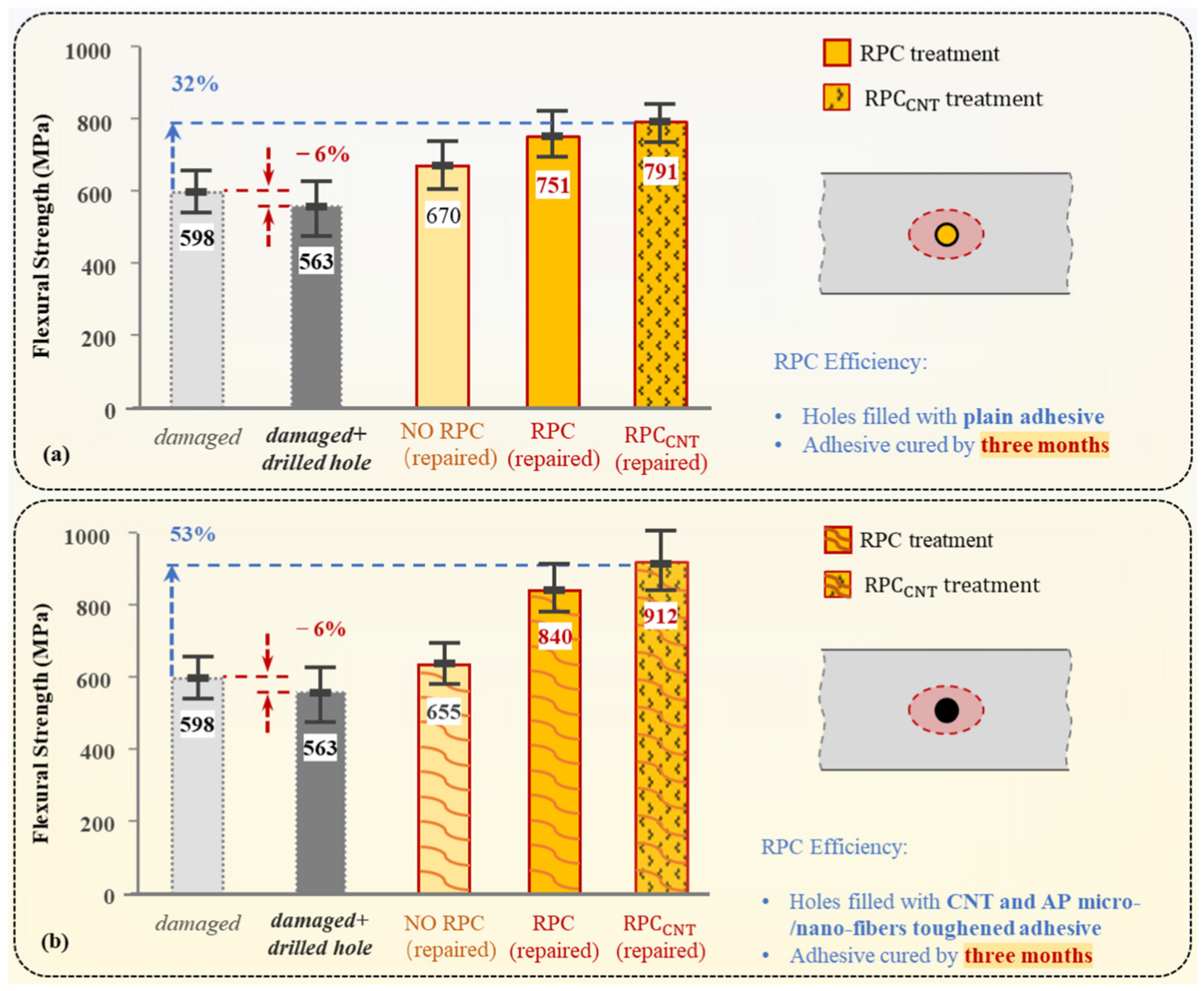
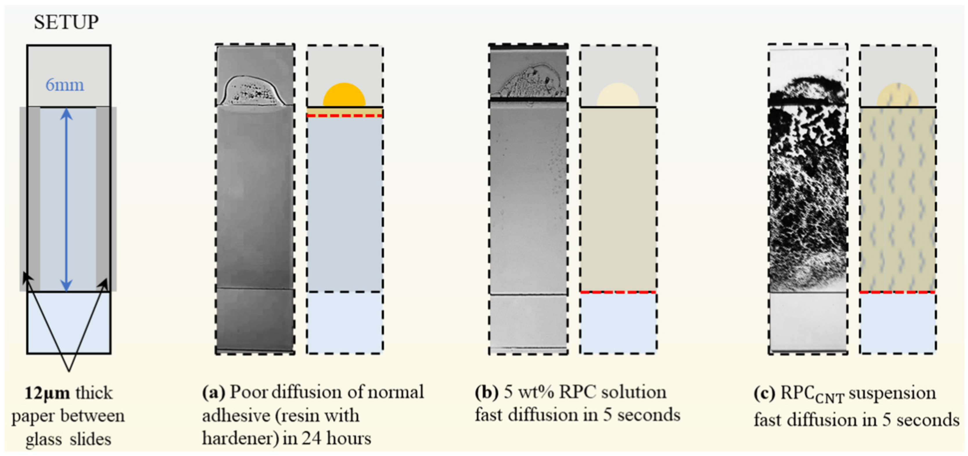
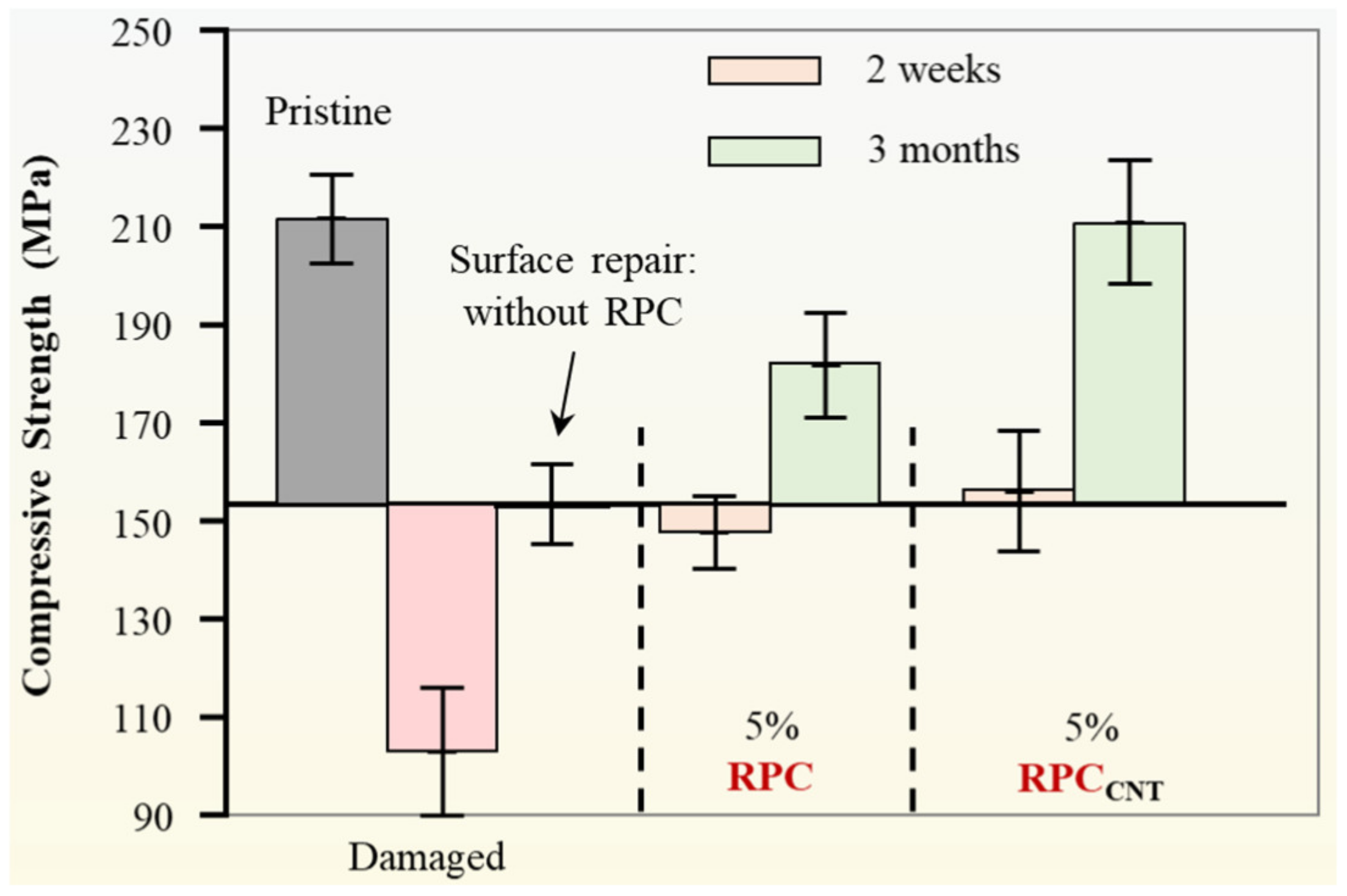
  • The RPC solution, consisting of 90 m/m% acetone and 10 m/m% resin, exhibited excellent penetration properties without requiring pressure. The repair results with and without RPC demonstrate that the acetone-rich RPC solution played a significant role in successful delamination repairs.
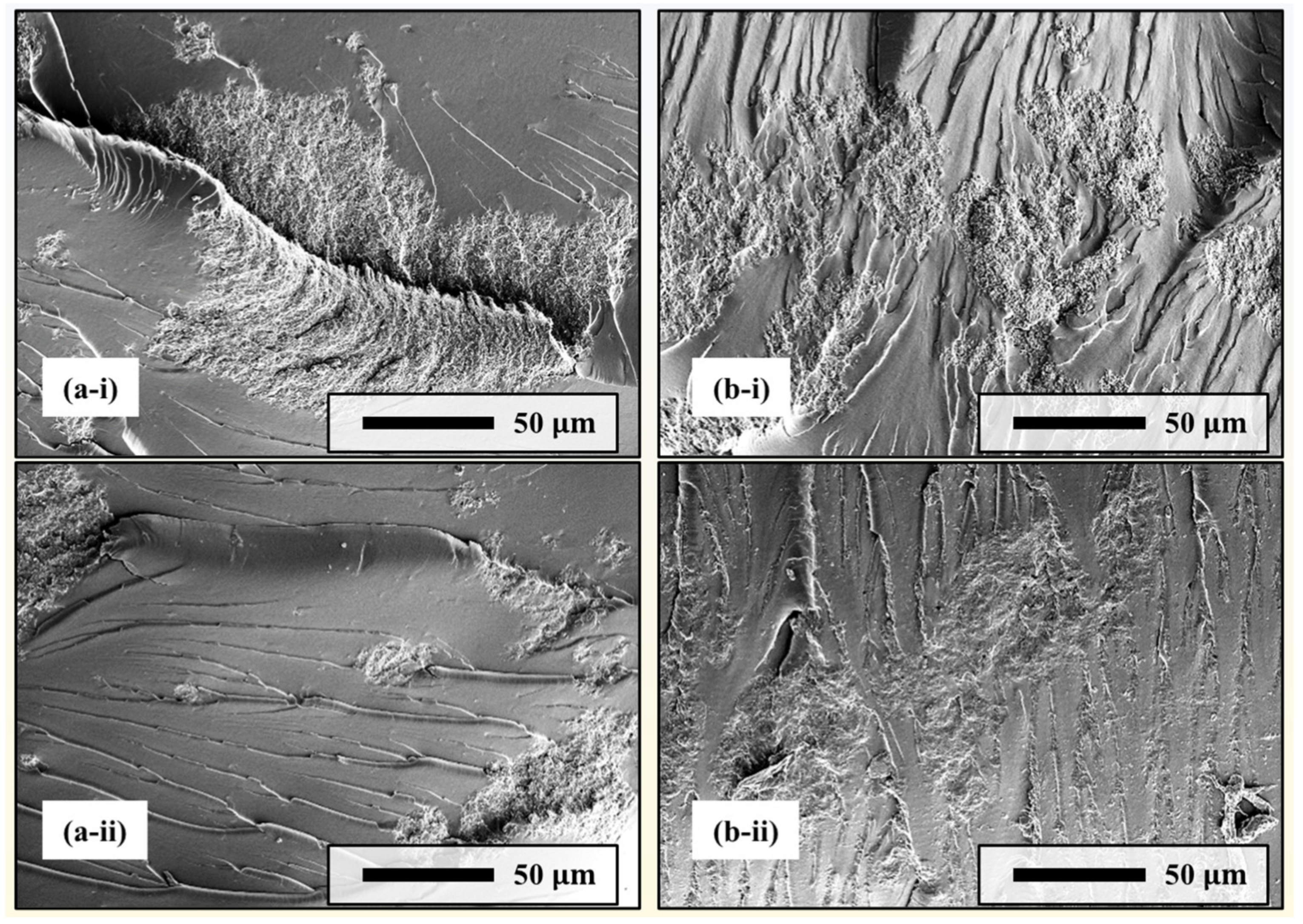
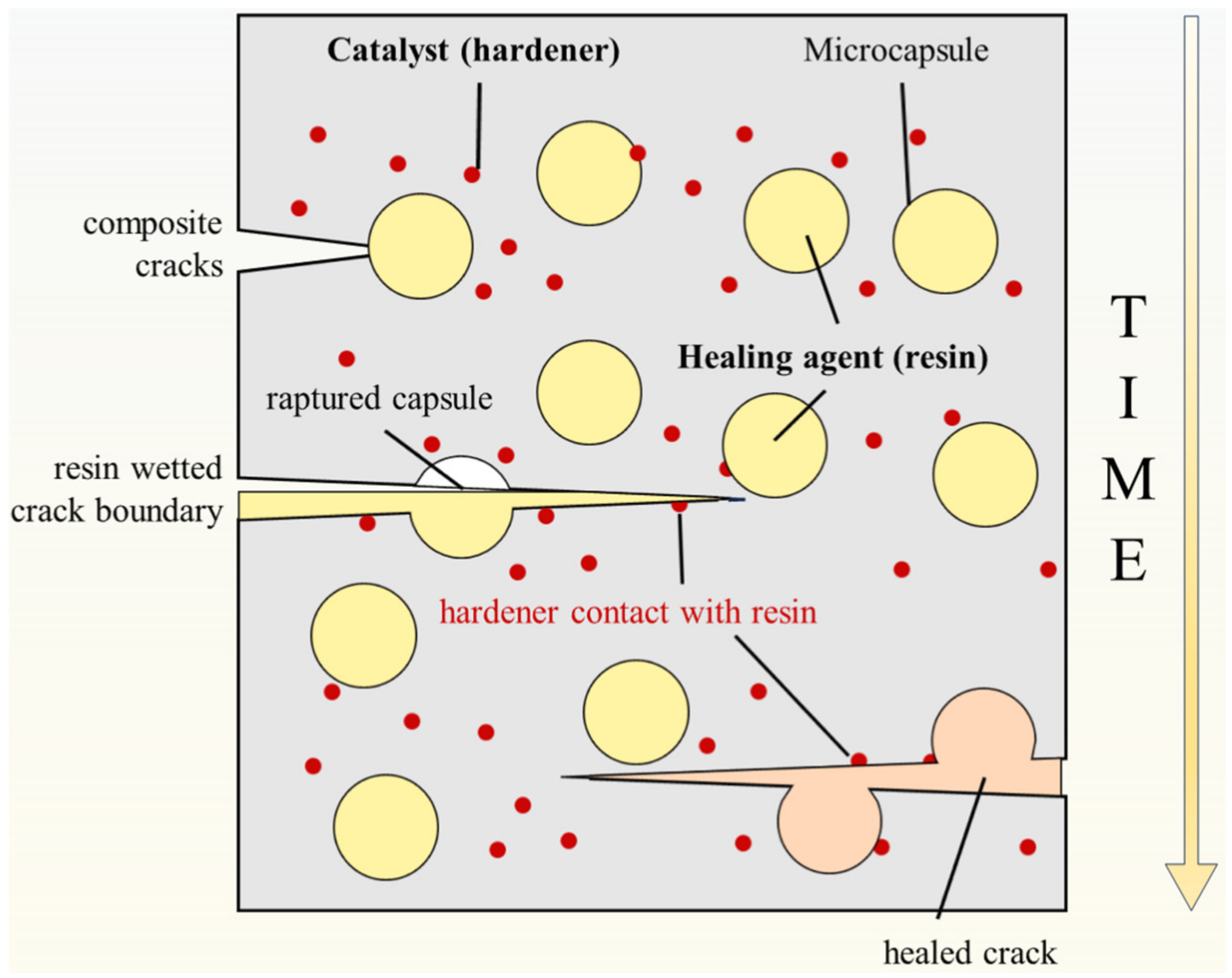
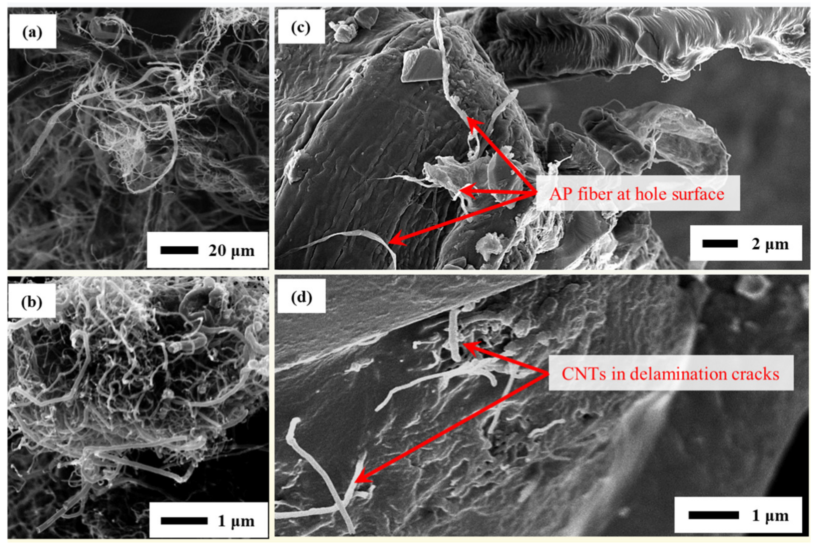
  • The CNT-containing RPC suspension, or RPCCNT, was found to be more effective due to CNT-toughening and strengthening of the filled adhesive. The RPC solution was able to transport CNT deep into narrow cracks.
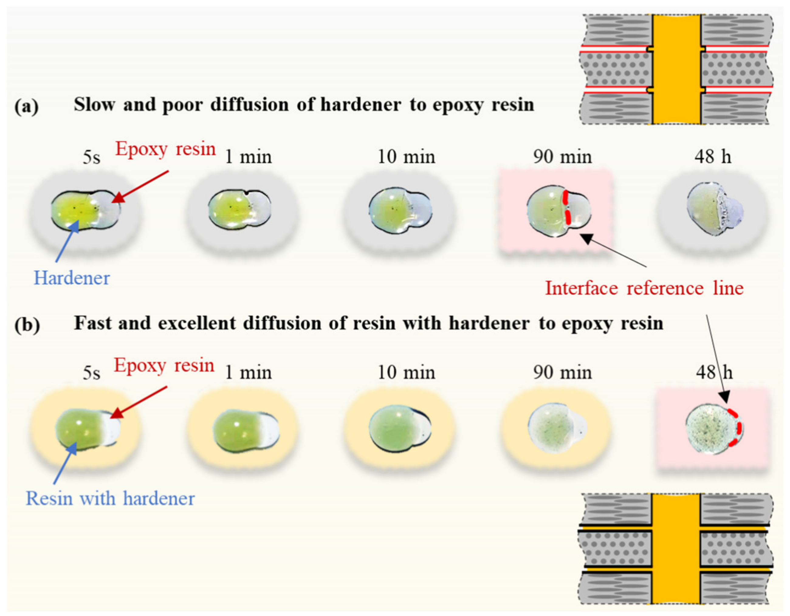
  • The contact curing experiments indicated that a resin and hardener mixture in contact with resin (without hardener) favored the “diffusion of polymerization” more than simple hardener and resin contact. A long curing period (>2 weeks), such as 3 months, was found to be necessary for complete contact curing, depending on the depth of the delamination cracks.
  • The CNT and AP micro-/nano-fibers-toughened epoxy for the drilled hole provided additional benefits due to fiber strengthening.

Author Contributions

G.H.: conceptualization, methodology, formal analysis, investigation, writing—original draft. X.H.: project administration, supervision, writing—review and editing. All authors have read and agreed to the published version of the manuscript.

Funding

This research received no external funding.

Data Availability Statement

The data presented in this study are available by request.

Conflicts of Interest

The authors declare that they have no known competing financial interests or personal relationships that could have appeared to influence the work reported in this paper.

References

  1. Shiekh, P.A.; Mohammed, S.A.; Gupta, S.; Das, A.; Meghwani, H.; Maulik, S.K.; Banerjee, S.K.; Kumar, A. Oxygen releasing and antioxidant breathing cardiac patch delivering exosomes promotes heart repair after myocardial infarction. Chem. Eng. J. 2022, 428, 132490. [Google Scholar] [CrossRef]
  2. Aabid, A.; Hrairi, M.; Ali, J.S.M. Optimization of composite patch repair for center-cracked rectangular plate using design of experiments method. Mater. Today Proc. 2020, 27, 1713–1719. [Google Scholar] [CrossRef]
  3. Fong, L.S.; Winlaw, D.S.; Orr, Y. Is the modified single-patch repair superior to the double-patch repair of complete atrioventricular septal defects? Interact. Cardiovasc. Thorac. Surg. 2019, 28, 427–431. [Google Scholar] [CrossRef] [PubMed]
  4. Srinivasan, D.V.; Padma, S.R.; Idapalapati, S. Comparative study of composite scarf and strap joints for equivalent repair signature under uniaxial tension. Compos. Part A Appl. Sci. Manuf. 2022, 158, 106950. [Google Scholar] [CrossRef]
  5. Campilho, R.D.S.G.; De Moura, M.F.S.F.; Pinto, A.M.G.; Morais, J.J.L.; Domingues, J.J.M.S. Modelling the tensile fracture behaviour of CFRP scarf repairs. Compos. Part B Eng. 2009, 40, 149–157. [Google Scholar] [CrossRef]
  6. Gunnion, A.J.; Herszberg, I. Parametric study of scarf joints in composite structures. Compos. Struct. 2006, 75, 364–376. [Google Scholar] [CrossRef]
  7. Yang, L.; Yang, Y.; He, S.; Chen, G.; Ao, C.; Zhang, W. Scarf patch repair of honeycomb sandwich composites and its simulation optimisation. Plast. Rubber Compos. 2021, 50, 307–314. [Google Scholar] [CrossRef]
  8. Sun, C.; Zhao, W.; Zhou, J.; Altenaiji, M.; Cantwell, W.J.; Wang, Q.Y.; Guan, Z.W. Mechanical behaviour of composite laminates repaired with a stitched scarf patch. Compos. Struct. 2021, 255, 112928. [Google Scholar] [CrossRef]
  9. Jiang, H.; Ren, Y.; Zhang, S.; Liu, Z.; Yu, G.; Xiang, J. Damage and perforation resistance behaviors induced by projectile impact load on bonding-patch repaired and scarf-patch repaired composite laminates. Int. J. Damage Mech. 2019, 28, 502–537. [Google Scholar] [CrossRef]
  10. Guan, W.; Su, Y.; Tong, G. Static and Fatigue Properties of Scarf Patch Repaired Composite Laminates: An Experimental Study. In IOP Conference Series: Materials Science and Engineering; IOP Publishing: Bristol, UK, 2019; Volume 677, p. 022010. [Google Scholar]
  11. Feng, W.; Xu, F.; Yuan, J.; Zang, Y.; Zhang, X. Focusing on in-service repair to composite laminates of different thicknesses via scarf-repaired method. Compos. Struct. 2019, 207, 826–835. [Google Scholar] [CrossRef]
  12. Lai, W.L.; Saeedipour, H.; Goh, K.L. Experimental assessment of drilling-induced damage in impacted composite laminates for resin-injection repair: Influence of open/blind hole-hole interaction and orientation. Compos. Struct. 2021, 271, 114153. [Google Scholar] [CrossRef]
  13. Lai, W.L.; Saeedipour, H.; Goh, K.L. Mechanical properties of low-velocity impact damaged carbon fibre reinforced polymer laminates: Effects of drilling holes for resin-injection repair. Compos. Struct. 2020, 235, 111806. [Google Scholar] [CrossRef]
  14. Thunga, M.; Bauer, A.; Obusek, K.; Meilunas, R.; Akinc, M.; Kessler, M.R. Injection repair of carbon fiber/bismaleimide composite panels with bisphenol E cyanate ester resin. Compos. Sci. Technol. 2014, 100, 174–181. [Google Scholar] [CrossRef]
  15. Lee, J.H.; Ge, J.C.; Song, J.H. Study on burr formation and tool wear in drilling CFRP and its hybrid composites. Appl. Sci. 2021, 11, 384. [Google Scholar] [CrossRef]
  16. Wang, Z.; Zhao, M.; Liu, K.; Yuan, K.; He, J. Experimental analysis and prediction of CFRP delamination caused by ice impact. Eng. Fract. Mech. 2022, 273, 108757. [Google Scholar] [CrossRef]
  17. Irwin, G.R. Linear fracture mechanics, fracture transition, and fracture control. Eng. Fract. Mech. 1968, 1, 241–257. [Google Scholar] [CrossRef]
  18. Han, G.; Tan, B.; Cheng, F.; Wang, B.; Leong, Y.K.; Hu, X. CNT toughened aluminium and CFRP interface for strong adhesive bonding. Nano Mater. Sci. 2022, 4, 266–275. [Google Scholar] [CrossRef]
  19. Wang, B.; Hu, X.; Hui, J.; Lu, P.; Jiang, B. CNT-reinforced adhesive joint between grit-blasted steel substrates fabricated by simple resin pre-coating method. J. Adhes. 2018, 94, 529–540. [Google Scholar] [CrossRef]
  20. Wang, B.; Bai, Y.; Hu, X.; Lu, P. Enhanced epoxy adhesion between steel plates by surface treatment and CNT/short-fibre reinforcement. Compos. Sci. Technol. 2016, 127, 149–157. [Google Scholar] [CrossRef]
  21. Han, G.; Yuan, B.; Hu, X. Restoration of Compressive Strength of CFRP Plates with Edge Delamination through CNT Crack-Bridging Deposited by Resin Pre-Coating Solution. Compos. Part A Appl. Sci. Manuf. 2023, 175, 107798. [Google Scholar] [CrossRef]
  22. Yu, X.; Shen, W.; Zhu, L.; Natsuki, T. The tensile properties and repair behavior of glass fiber reinforced polymer using resin pre-coating technology. Text. Res. J. 2023, 93, 5187–5197. [Google Scholar] [CrossRef]
  23. Ji, Y.; Chen, Y.; Han, X.; Hu, X.; Yuan, B.; Qiao, Y. Effect of acetone on mechanical properties of epoxy used for surface treatment before adhesive bonding. Polym. Test. 2020, 86, 106492. [Google Scholar] [CrossRef]
  24. Perez, N. Linear Elastic Fracture Mechanics; Springer: New York, NY, USA, 2004; pp. 39–72. [Google Scholar]
  25. Ricotta, M.; Quaresimin, M.; Talreja, R. Mode I strain energy release rate in composite laminates in the presence of voids. Compos. Sci. Technol. 2008, 68, 2616–2623. [Google Scholar] [CrossRef]
  26. Roucou, D.; Diani, J.; Brieu, M.; Mbiakop-Ngassa, A. Critical strain energy release rate for rubbers: Single edge notch tension versus pure shear tests. Int. J. Fract. 2019, 216, 31–39. [Google Scholar] [CrossRef]
  27. Lerpiniere, A.; Caron, J.F.; Diaz, A.D.; Sab, K. The LS1 model for delamination propagation in multilayered materials at 0°/θ° interfaces: A comparison between experimental and finite elements strain energy release rates. Int. J. Solids Struct. 2014, 51, 3973–3986. [Google Scholar] [CrossRef]
  28. Song, S.H.; Paulino, G.H.; Buttlar, W.G. A bilinear cohesive zone model tailored for fracture of asphalt concrete considering viscoelastic bulk material. Eng. Fract. Mech. 2006, 73, 2829–2848. [Google Scholar] [CrossRef]
  29. Choi, H.; Park, K.; Paulino, G.H. Mixed-mode fatigue crack growth using cohesive zone modeling. Eng. Fract. Mech. 2020, 240, 107234. [Google Scholar] [CrossRef]
  30. Xu, J.; Lin, T.; Davim, J.P.; Chen, M.; El Mansori, M. Wear behavior of special tools in the drilling of CFRP composite laminates. Wear 2021, 476, 203738. [Google Scholar] [CrossRef]
  31. Xu, C.; Wang, Y.; Xu, J.; Liu, X. Design of internal-chip-removal drill for CFRP drilling and study of influencing factors of drilling quality. Int. J. Adv. Manuf. Technol. 2020, 106, 1657–1669. [Google Scholar] [CrossRef]
  32. Kwon, B.C.; Mai, N.D.D.; Cheon, E.S.; Ko, S.L. Development of a step drill for minimization of delamination and uncut in drilling carbon fiber reinforced plastics (CFRP). Int. J. Adv. Manuf. Technol. 2020, 106, 1291–1301. [Google Scholar] [CrossRef]
  33. Qiu, X.; Li, P.; Li, C.; Niu, Q.; Chen, A.; Ouyang, P.; Ko, T.J. New compound drill bit for damage reduction in drilling CFRP. Int. J. Precis. Eng. Manuf.-Green Technol. 2019, 6, 75–87. [Google Scholar] [CrossRef]
  34. Su, F.; Zheng, L.; Sun, F.; Wang, Z.; Deng, Z.; Qiu, X. Novel drill bit based on the step-control scheme for reducing the CFRP delamination. J. Mater. Process. Technol. 2018, 262, 157–167. [Google Scholar] [CrossRef]
  35. Kanu, N.J.; Gupta, E.; Vates, U.K.; Singh, G.K. Self-healing composites: A state-of-the-art review. Compos. Part A Appl. Sci. Manuf. 2019, 121, 474–486. [Google Scholar] [CrossRef]
  36. Patrick, J.F.; Robb, M.J.; Sottos, N.R.; Moore, J.S.; White, S.R. Polymers with autonomous life-cycle control. Nature 2016, 540, 363–370. [Google Scholar] [CrossRef]
  37. ASTM D3410/D3410M-16e1; Standard Test Method for Compressive Properties of Polymer Matrix Composite Materials with Unsupported Gage Section by Shear Loading. ASTM International: West Conshohocken, PA, USA, 2006.
  38. Thunga, M.; Larson, K.; Lio, W.; Weerasekera, T.; Akinc, M.; Kessler, M.R. Low viscosity cyanate ester resin for the injection repair of hole-edge delaminations in bismaleimide/carbon fiber composites. Compos. Part A Appl. Sci. Manuf. 2013, 52, 31–37. [Google Scholar] [CrossRef]
Figure 2. (a) Small-area delamination around a few millimeters may be too small for scarf and patch repair. A small drilled hole at the delamination site with a pressureless resin pre-coating (RPC) can “ideally” repair small-area delamination cracks by the same ideal adhesive infill mode demonstrated in (b) to prevent further delamination propagation as shown in (c).
Inorganics 11 00454 g002
Figure 3. (a) Cross-section of a small drilled hole at the delamination site, and the infill using epoxy (resin with hardener) is hindered by the limited delamination crack opening and high epoxy viscosity. (b) Through capillary action, the RPC solution can fill the entire delamination crack (left), then a normal adhesive (resin and hardener) is used to fill the drilled hole. Partial curing within the delamination cracks in two weeks (middle) and completely cured in three months (right). (c) The RPCCNT suspension is used for the optimum repair result (left), followed by a normal epoxy adhesive with a two-week curing period (middle), and complete curing after three months (right). (d) The drilled hole can also be reinforced by epoxy with aramid pulp micro-/nano-fibers and CNT.
Inorganics 11 00454 g003
Figure 4. (a-i) and (a-ii): CNT mixed with adhesive directly witnesses an uneven distribution in the cured adhesive block and trunky fibers can only accumulate at separate spots; (b-i) and (b-ii) CNT dispersed into the RPC solution can distribute more evenly and disentangled fibers tend to increase the roughness of the entire surface.
Inorganics 11 00454 g004
Figure 5. CFRP specimens with dimensions of 100 mm × 20 mm × 2 mm were compressed by 2450 N. The supporting base has a 25 mm × 10 mm hole in the middle. A small delamination zone (around 10 mm × 5 mm) was generated. Micro-CT scan of the CFRP (a) before and (b) after drilling the small hole (2 mm in diameter) on the damaged CFRP strip.
Inorganics 11 00454 g005
Figure 6. The specimens with the drilled hole and delamination damage (10 per group) have similar flexural strengths (582–598 MPa). The drilled hole through the delamination area has limited influence on the flexural strength (598 ⟶ 563 MPa).
Inorganics 11 00454 g006
Figure 7. Contact curing in self-repaired composites [35,36], i.e., no resin and hardener mixing, and the polymerization (or curing) occurred through surface contact and “diffusion”.
Inorganics 11 00454 g007
Figure 8. Epoxy contact curing on clean glass slide. (a) Slow contact “diffusion” of hardener ⟶ resin (without hardener). Curing of the contact interface started at 90 min. There was little change around the original contact region, even after 48 h. (b) Fast contact “diffusion” of the resin/hardener mixture ⟶ resin (without hardener). After 90 min, self-mixing and curing had occurred. The curing process was continued for 48 h.
Inorganics 11 00454 g008
Figure 9. Flexural strength (3-P-B) with drilled hole effects and reinforcements, and with a 3-month curing period. (a) Drilled hole filled with plain epoxy (except 2nd condition), (b) drilled hole filled with CNT and AP micro-/nano-fiber-toughened epoxy (except 2nd condition). Each group contains 10 specimens. Without RPC, the drill hole reinforcements have no effect. RPCCNT together with drilled hole reinforcements produced the best repair result.
Inorganics 11 00454 g009
Figure 10. Infiltration experiments between two glass slides. (a) Very limited infiltration from normal epoxy adhesive (resin + hardener), even after 24 h, due to its high viscosity. (b) The acetone-rich RPC solution filled the micro-opening between the two glass slides in 5 s. (c) The RPCCNT suspension also filled in the micro-opening in 5 s, as shown by the distributed black CNT.
Inorganics 11 00454 g010
Figure 11. Effect of curing time periods (2 weeks and 3 months) on RPC and RPCCNT repairs. By 2 weeks, the RPC and RPCCNT produced similar results. By 3 months, the RPCCNT produced noticeably higher strengths.
Inorganics 11 00454 g011
Figure 12. (a) Aramid pulp (AP) micro-/nano-fibers with diameters from around 200 nm up to around 8 μm and lengths less than around 500 μm. (b) CNT with a diameter from around 5 nm to 100 nm and a length of up to 10 μm. The RPC solution was used to wet the CNT and AP first, for easy mixing and removal of air pockets. (c) AP fibers are witnessed at drilled hole surface and (d) CNTs are well engineered into the delamination cracks by the RPC solution.
Inorganics 11 00454 g012
Figure 13. Drilled hole epoxy filling with and without CNT–AP toughening, based on the 3-month curing period. The best result is from RPCCNT with the CNT–AP-toughened epoxy filling of the drilled hole.
Inorganics 11 00454 g013
Figure 14. Edge delamination repair using the same RPCCNT method (used for the repair of the small-area delamination with a drilled hole), which produced 100% restoration of the compressive strength [26].
Inorganics 11 00454 g014
Figure 15. (a) Small delamination area (around 10 × 5 mm) was generated in the CFRP specimen of 20 mm wide (left) and a 2 mm drilled hole was introduced at the center. (b) All CFRP specimens were put into the resin pre-coating (RPC) solution or RPCCNT suspension and then taken out to allow quick evaporation of the acetone. The RPC process was repeated several times to ensure the delamination cracks were fully filled. (c) Final filling with epoxy (resin and hardener mixture) or with CNT and micro-fiber-toughened epoxy (with hardener) for the long process of curing or polymerization within the thin resin fillings (no hardener) in the delamination cracks deposited by RPC.
Inorganics 11 00454 g015
Disclaimer/Publisher’s Note: The statements, opinions and data contained in all publications are solely those of the individual author(s) and contributor(s) and not of MDPI and/or the editor(s). MDPI and/or the editor(s) disclaim responsibility for any injury to people or property resulting from any ideas, methods, instructions or products referred to in the content.

