
Two Birds with One Stone: Ammonium-Induced Carbon Nanotube Structure and Low-Crystalline Cobalt Nanoparticles Enabling High Performance of Lithium-Sulfur Batteries

Abstract
:1. Introduction
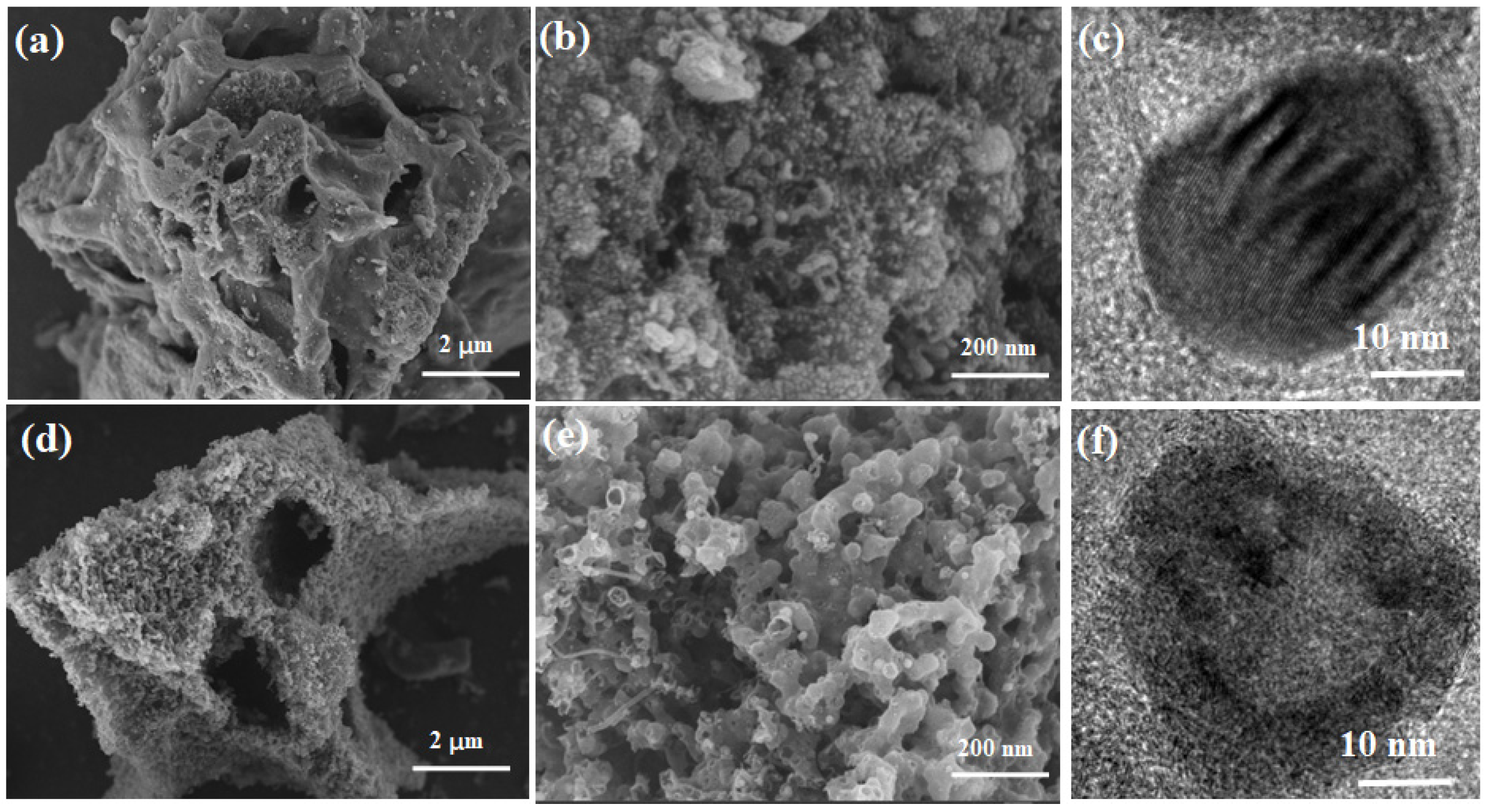
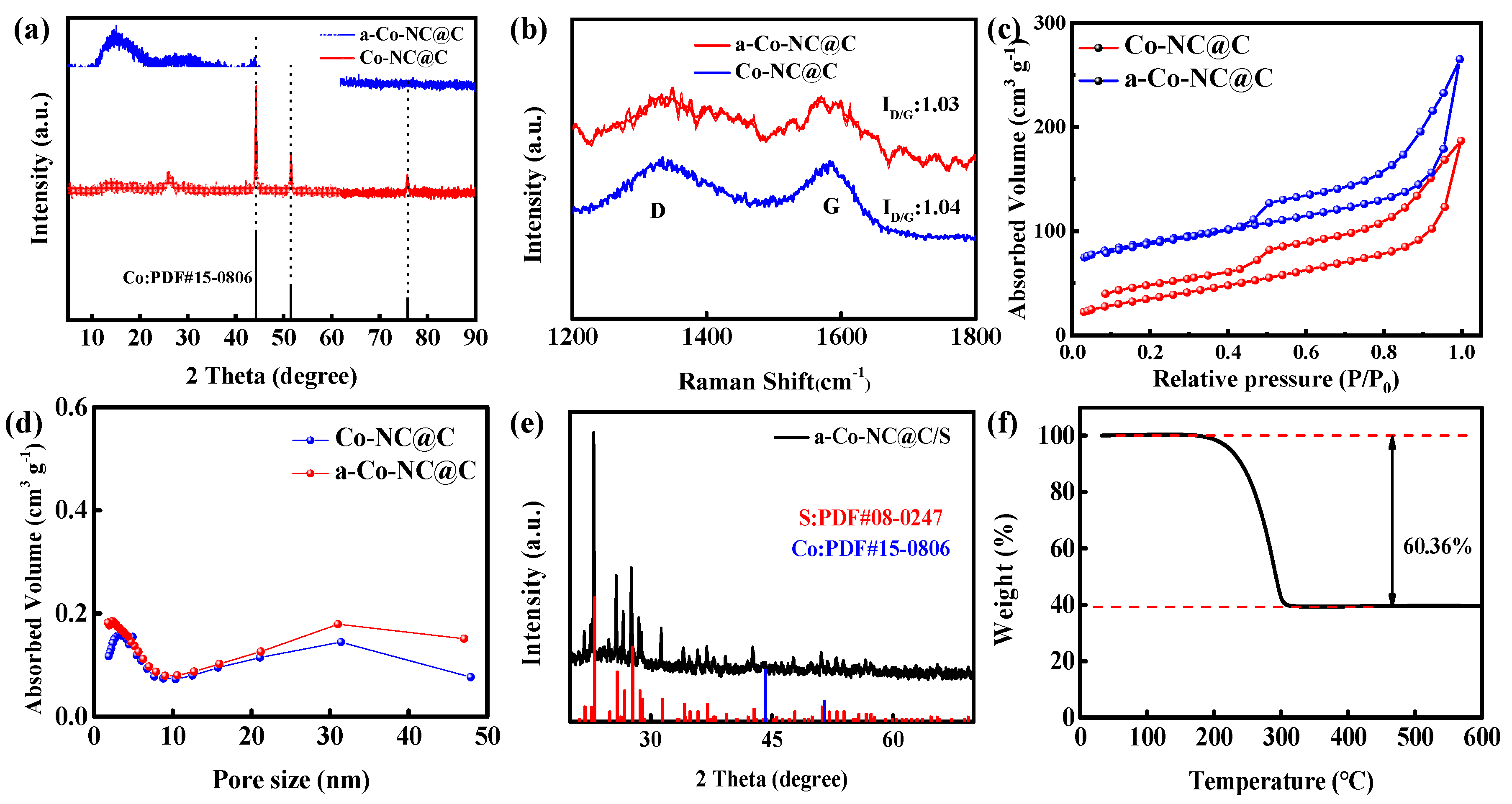
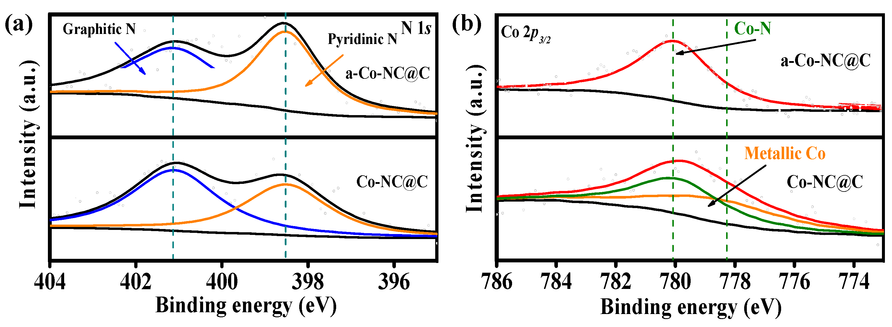
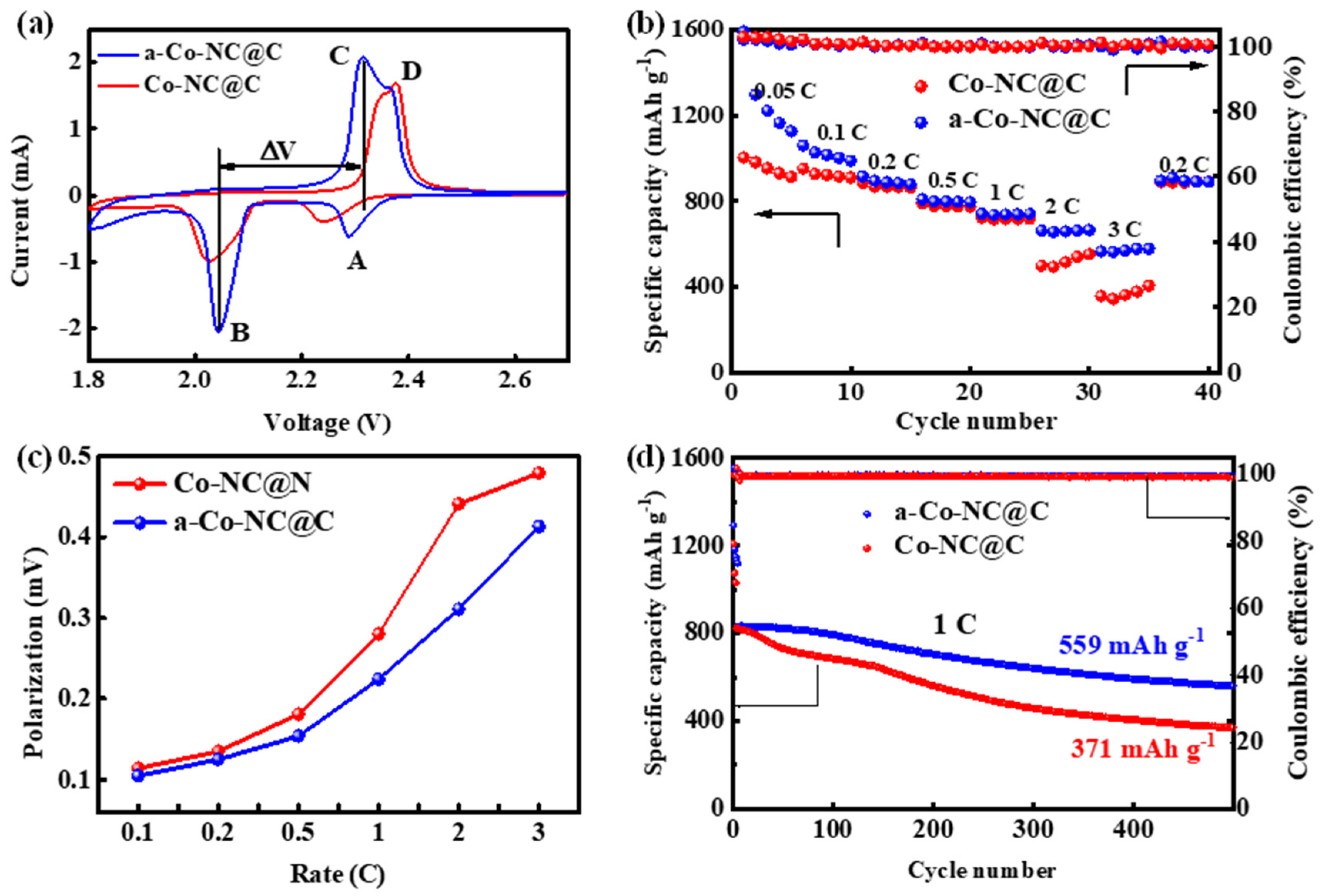
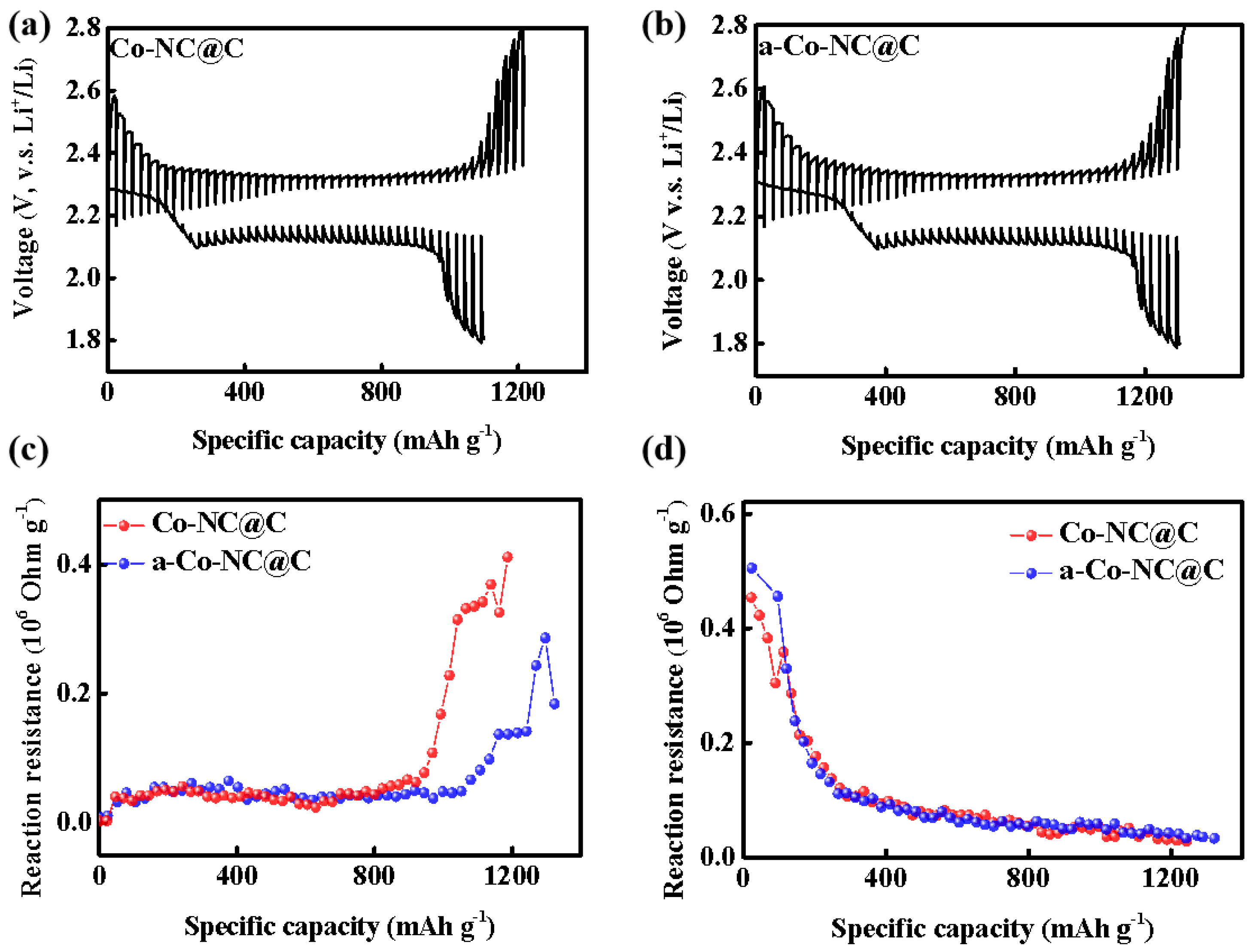
2. Results
3. Materials and Methods
3.1. Materials
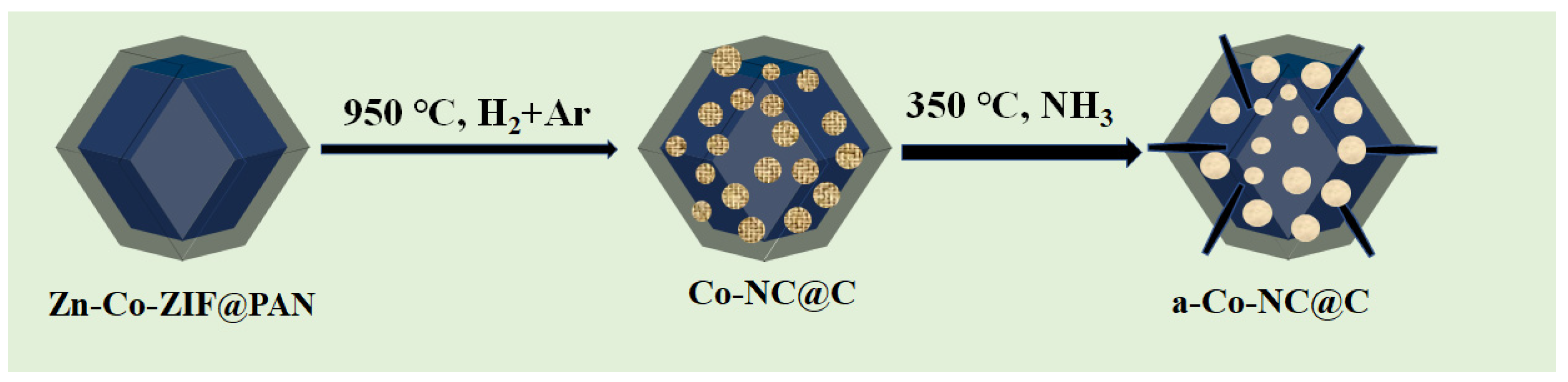
3.1.1. Synthesis of Zn–Co-ZIF and Zn–Co-ZIF@PAN
3.1.2. Preparation of Co-NC@C and a-Co-NC@C
3.1.3. Sulfur Loading to Co-NC@C and a-Co-NC@C
3.2. Electrochemical Measurements
3.3. The Assembly of Batteries
4. Conclusions
Supplementary Materials
Author Contributions
Funding
Data Availability Statement
Conflicts of Interest
References
- Wu, Q.; Zhou, X.; Xu, J.; Cao, F.; Li, C. Carbon-Based Derivatives from Metal-Organic Frameworks as Cathode Hosts for Li–S batteries. J. Energy Chem. 2019, 38, 94–113. [Google Scholar] [CrossRef] [Green Version]
- Yu, S.; Cai, W.; Chen, L.; Song, L.; Song, Y. Recent Advances of Metal Phosphides for Li–S Chemistry. J. Energy Chem. 2021, 55, 533–548. [Google Scholar] [CrossRef]
- Xu, R.; Lu, J.; Amine, K. Progress in Mechanistic Understanding and Characterization Techniques of Li-S Batteries. Adv. Energy Mater. 2015, 5, 1500408. [Google Scholar] [CrossRef]
- Jamesh, M.-I. Recent advances on flexible electrodes for Na-ion batteries and Li–S batteries. J. Energy Chem. 2019, 32, 15–44. [Google Scholar] [CrossRef] [Green Version]
- Tong, Z.; Huang, L.; Lei, W.; Zhang, H.; Zhang, S. Carbon-containing Electrospun Nanofibers for Lithium–Sulfur Battery: Current status and future directions. J. Energy Chem. 2021, 54, 254–273. [Google Scholar] [CrossRef]
- Chen, J.; Dong, Q. Research Progress of Key Components in Lithium-Sulfur Batteries. J. Electrochem. 2020, 26, 648–662. [Google Scholar] [CrossRef]
- Seh, Z.W.; Sun, Y.; Zhang, Q.; Cui, Y. Designing High-energy Lithium-Sulfur Batteries. Chem. Soc. Rev. 2016, 45, 5605–5634. [Google Scholar] [CrossRef] [PubMed]
- Zhao, G.; Ahmed, W.H.Z.; Zhu, F. Nitrogen-Sulfur Co-Doped Porous Carbon Preparation and Its Application in Lithium-Sulfur Batteries. J. Electrochem. 2021, 27, 614–623. [Google Scholar] [CrossRef]
- Kai, W. Preparation and Process Optimization of Cathode Materials for Lithium-Sulfur Batteries. J. Electrochem. 2020, 26, 825–833. [Google Scholar] [CrossRef]
- Manthiram, A.; Fu, Y.; Chung, S.H.; Zu, C.; Su, Y.S. Rechargeable lithium-sulfur batteries. Chem. Rev. 2014, 114, 11751–11787. [Google Scholar] [CrossRef]
- Ali, T.; Yan, C. 2 D Materials for Inhibiting the Shuttle Effect in Advanced Lithium-Sulfur Batteries. ChemSusChem 2020, 13, 1447–1479. [Google Scholar] [CrossRef] [PubMed]
- Wei, Z.; Zhang, N.; Wu, F.; Chen, R. Progress and Prospects on Multifunctional Coating Separators for Lithium-Sulfur Battery. J. Electrochem. 2020, 26, 716–730. [Google Scholar] [CrossRef]
- Chen, Y.; Wang, T.; Tian, H.; Su, D.; Zhang, Q.; Wang, G. Advances in Lithium-Sulfur Batteries: From Academic Research to Commercial Viability. Adv. Mater. 2021, 33, e2003666. [Google Scholar] [CrossRef]
- Chung, S.H.; Manthiram, A. Current Status and Future Prospects of Metal-Sulfur Batteries. Adv. Mater. 2019, 31, e1901125. [Google Scholar] [CrossRef]
- Zhang, S.S. Liquid electrolyte lithium/sulfur battery: Fundamental Chemistry, Problems, and Solutions. J. Power Sources 2013, 231, 153–162. [Google Scholar] [CrossRef]
- Ji, S.; Imtiaz, S.; Sun, D.; Xin, Y.; Li, Q.; Huang, T.; Zhang, Z.; Huang, Y. Coralline-Like N-Doped Hierarchically Porous Carbon Derived from Enteromorpha as a Host Matrix for Lithium-Sulfur Battery. Chem.—A Eur. J. 2017, 23, 18208–18215. [Google Scholar] [CrossRef]
- Xia, Y.; Fang, R.; Xiao, Z.; Huang, H.; Gan, Y.; Yan, R.; Lu, X.; Liang, C.; Zhang, J.; Tao, X.; et al. Confining Sulfur in N-Doped Porous Carbon Microspheres Derived from Microalgaes for Advanced Lithium-Sulfur Batteries. ACS Appl. Mater. Interfaces 2017, 9, 23782–23791. [Google Scholar] [CrossRef]
- Yu, L.; Yu, X.Y.; Lou, X.W.D. The Design and Synthesis of Hollow Micro-/Nanostructures: Present and Future Trends. Adv. Mater. 2018, 30, e1800939. [Google Scholar] [CrossRef] [PubMed]
- Li, Y.-J.; Fan, J.-M.; Zheng, M.-S.; Dong, Q.-F. A Novel Synergistic Composite with Multi-functional Effects for High-Performance Li–S Batteries. Energy Environ. Sci. 2016, 9, 1998–2004. [Google Scholar] [CrossRef]
- Kong, Z.; Liu, Q.; Liu, X.; Wang, Y.; Shen, C.; Zhan, L. Co-Nx bonds as Bifunctional Electrocatalytic Sites to Drive The Reversible Conversion of Lithium Polysulfides for Long Life Lithium Sulfur Batteries. Appl. Surf. Sci. 2021, 546, 148914. [Google Scholar] [CrossRef]
- Zhou, Y.; Fan, H.J. Progress and Challenge of Amorphous Catalysts for Electrochemical Water Splitting. ACS Mater. Lett. 2021, 3, 136–147. [Google Scholar] [CrossRef]
- Anantharaj, S.; Noda, S. Amorphous Catalysts and Electrochemical Water Splitting: An Untold Story of Harmony. Small 2020, 16, 1905779. [Google Scholar] [CrossRef]
- Gao, H.; Ning, S.; Zhou, Y.; Men, S.; Kang, X. Polyacrylonitrile-induced Formation of Core-Shell Carbon Nanocages: Enhanced Redox Kinetics towards Polysulfides by Confined Catalysis in Li-S Batteries. Chem. Eng. J. 2021, 408, 127323. [Google Scholar] [CrossRef]
- Meng, J.; Niu, C.; Xu, L.; Li, J.; Liu, X.; Wang, X.; Wu, Y.; Xu, X.; Chen, W.; Li, Q.; et al. General Oriented Formation of Carbon Nanotubes from Metal–Organic Frameworks. J. Am. Chem. Soc. 2017, 139, 8212–8221. [Google Scholar] [CrossRef]
- Li, R.; Rao, D.; Zhou, J.; Wu, G.; Wang, G.; Zhu, Z.; Han, X.; Sun, R.; Li, H.; Wang, C.; et al. Amorphization-induced Surface Electronic States Modulation of Cobaltous Oxide Nanosheets for Lithium-sulfur Batteries. Nat. Commun. 2021, 12, 3102. [Google Scholar] [CrossRef] [PubMed]
- Zhang, S.; Zeng, X.T.; Xie, H.; Hing, P. A Phenomenological Approach for The Id/Ig Ratio and sp3 Fraction of Magnetron Sputtered a-C Films. Surf. Coat. Technol. 2000, 123, 256–260. [Google Scholar] [CrossRef]
- Li, C.; Sui, X.-L.; Wang, Z.-B.; Wang, Q.; Gu, D.-M. 3D N-doped Graphene Nanomesh Foam for Long Cycle Life Lithium-Sulfur Battery. Chem. Eng. J. 2017, 326, 265–272. [Google Scholar] [CrossRef]
- Wang, J.; Luo, D.; Li, J.; Zhang, Y.; Zhao, Y.; Zhou, G.; Shui, L.; Chen, Z.; Wang, X. “Soft on Rigid” Nanohybrid as The Self-supporting Multifunctional Cathode Electrocatalyst for High-performance Lithium-Polysulfide Batteries. Nano Energy 2020, 78, 105293. [Google Scholar] [CrossRef]
- Chen, J.-J.; Yuan, R.-M.; Feng, J.-M.; Zhang, Q.; Huang, J.-X.; Fu, G.; Zheng, M.-S.; Ren, B.; Dong, Q.-F. Conductive Lewis Base Matrix to Recover the Missing Link of Li2S8 during the Sulfur Redox Cycle in Li–S Battery. Chem. Mater. 2015, 27, 2048–2055. [Google Scholar] [CrossRef]
- Cho, Y.J.; Kim, H.S.; Im, H.; Myung, Y.; Jung, G.B.; Lee, C.W.; Park, J.; Park, M.-H.; Cho, J.; Kang, H.S. Nitrogen-Doped Graphitic Layers Deposited on Silicon Nanowires for Efficient Lithium-Ion Battery Anodes. J. Phys. Chem. C 2011, 115, 9451–9457. [Google Scholar] [CrossRef]
- Yuan, H.; Zhang, W.; Wang, J.-g.; Zhou, G.; Zhuang, Z.; Luo, J.; Huang, H.; Gan, Y.; Liang, C.; Xia, Y.; et al. Facilitation of Sulfur Evolution Reaction by Pyridinic Nitrogen Doped Carbon Nanoflakes for Highly-Stable Lithium-Sulfur Batteries. Energy Storage Mater. 2018, 10, 1–9. [Google Scholar] [CrossRef]
- Luo, M.; Cai, J.; Zou, J.; Jiang, Z.; Wang, G.; Kang, X. Promoted Alkaline Hydrogen Evolution by An N-Doped Pt–Ru Single Atom Alloy. J. Mater. Chem. A 2021, 9, 14941–14947. [Google Scholar] [CrossRef]
- Yao, S.; Xue, S.; Peng, S.; Jing, M.; Qian, X.; Shen, X.; Li, T.; Wang, Y. Synthesis of Graphitic Carbon Nitride at Different Thermal-Pyrolysis Temperature of Urea and Its Application in Lithium–Sulfur Batteries. J. Mater. Sci.-Mater. Electron. 2018, 29, 17921–17930. [Google Scholar] [CrossRef]
- Wang, N.; Xu, Z.; Xu, X.; Liao, T.; Tang, B.; Bai, Z.; Dou, S. Synergistically Enhanced Interfacial Interaction to Polysulfide via N,O Dual-Doped Highly Porous Carbon Microrods for Advanced Lithium–Sulfur Batteries. ACS Appl. Mater. Interfaces 2018, 10, 13573–13580. [Google Scholar] [CrossRef] [Green Version]
- Zhang, B.; Liu, X.; Li, D. Electrochemical Properties of Sulfur in Different Carbon Support Materials. J. Electrochem. 2019, 25, 749–756. [Google Scholar] [CrossRef]
- Wang, J.; Peng, Q.; Guan, Y.; Wang, W.; Wang, A.; Liu, Q.; Huang, Y. Efficient Interface Enabled by Nano-Hydroxyapatite@Porous Carbon for Lithium-Sulfur Batteries. J. Electrochem. 2022, 28, 2219008. [Google Scholar] [CrossRef]
- Ji, X.; Wang, J.Y.; Wang, A.B.; Wang, W.K.; Yao, M.; Huang, Y.Q. Preparation of Highly-Cyclized Sulfurized Polyacrylonitrile for Lithium-Sulfur Batteries. J. Electrochem. 2022, 28, 2219010. [Google Scholar] [CrossRef]
- Li, X.Y.; Zhao, C.X.; Li, B.Q.; Huang, J.Q.; Zhang, Q. Advances on Composite Cathodes for Lithium-Sulfur Batteries. J. Electrochem. 2022, 28, 2219013. [Google Scholar] [CrossRef]
- Gao, H.C.; Ning, S.L.; Lin, J.J.; Kang, X.W. Molecular Perturbation of 2D Organic Modifiers on Porous Carbon Interlayer: Promoted Redox Kinetics of Polysulfides in Lithium-Sulfur Batteries. Energy Storage Mater. 2021, 40, 312–319. [Google Scholar] [CrossRef]
- Gao, H.; Ning, S.; Zou, J.; Men, S.; Zhou, Y.; Wang, X.; Kang, X. The Electrocatalytic Activity of BaTiO3 Nanoparticles towards Polysulfides Enables High-Performance Lithium–Sulfur Batteries. J. Energy Chem. 2020, 48, 208–216. [Google Scholar] [CrossRef]
- Rana, M.; Ahad, S.A.; Li, M.; Luo, B.; Wang, L.; Gentle, I.; Knibbe, R. Review on Areal Capacities and Long-Term Cycling Performances of Lithium Sulfur Battery at High Sulfur Loading. Energy Storage Mater. 2019, 18, 289–310. [Google Scholar] [CrossRef]
- Peng, J.; Huang, J.; Cheng, X.; Zhang, Q. Review on High-Loading and High-Energy Lithium–Sulfur Batteries. Adv. Energy Mater. 2017, 7, 1700260. [Google Scholar] [CrossRef]

Disclaimer/Publisher’s Note: The statements, opinions and data contained in all publications are solely those of the individual author(s) and contributor(s) and not of MDPI and/or the editor(s). MDPI and/or the editor(s) disclaim responsibility for any injury to people or property resulting from any ideas, methods, instructions or products referred to in the content. |
© 2023 by the authors. Licensee MDPI, Basel, Switzerland. This article is an open access article distributed under the terms and conditions of the Creative Commons Attribution (CC BY) license (https://creativecommons.org/licenses/by/4.0/).
Share and Cite
Tan, Q.; Liu, H.; Liang, G.; Jiang, K.; Xie, H.; Si, W.; Lin, J.; Kang, X. Two Birds with One Stone: Ammonium-Induced Carbon Nanotube Structure and Low-Crystalline Cobalt Nanoparticles Enabling High Performance of Lithium-Sulfur Batteries. Inorganics 2023, 11, 305. https://doi.org/10.3390/inorganics11070305
Tan Q, Liu H, Liang G, Jiang K, Xie H, Si W, Lin J, Kang X. Two Birds with One Stone: Ammonium-Induced Carbon Nanotube Structure and Low-Crystalline Cobalt Nanoparticles Enabling High Performance of Lithium-Sulfur Batteries. Inorganics. 2023; 11(7):305. https://doi.org/10.3390/inorganics11070305
Chicago/Turabian StyleTan, Qi, Hongliang Liu, Guozhu Liang, Kaigui Jiang, Hangxuan Xie, Weijie Si, Jiajv Lin, and Xiongwu Kang. 2023. "Two Birds with One Stone: Ammonium-Induced Carbon Nanotube Structure and Low-Crystalline Cobalt Nanoparticles Enabling High Performance of Lithium-Sulfur Batteries" Inorganics 11, no. 7: 305. https://doi.org/10.3390/inorganics11070305