
Numerical Simulation of a Valorisation-Oriented Hybrid Process for the Bio-Oil-Related Separation of Acetol and Acetic Acid


1
Department of Chemical Engineering, University of Chemical Technology and Metallurgy, 8 Boulevard Kliment Ohridski, 1756 Sofia, Bulgaria
2
Process and Materials Sciences Laboratory (LSPM)—CNRS UPR 3407, Sorbonne Paris Nord University, 99 Avenue Jean-Baptiste Clément, 93430 Villetaneuse, France
*
Author to whom correspondence should be addressed.
ChemEngineering 2024, 8(1), 5; https://doi.org/10.3390/chemengineering8010005
Submission received: 18 October 2023
/
Revised: 9 December 2023
/
Accepted: 16 December 2023
/
Published: 22 December 2023
(This article belongs to the Special Issue Feature Papers in Chemical Engineering)
Abstract
:Biomass as a whole offers a more diverse potential for valorisation than any other renewable energy source. As one of the stages in the separation of bio-oil involves a liquid mixture of acetol and acetic acid, and as both components are particularly well suited for valorisation, a hybrid method was developed for their separation with a high purity level through an approach combining liquid–liquid extraction and distillation. In order to design and simulate the flowsheet, the ChemCAD 7.0 simulation software was used. Sensitivity analyses were carried out to investigate the influence of the different parameters in the distillation columns, such as the reflux ratio, the feed stage location, and the vapour/bottom molar flow ratio. The effect of different extractants and of their excess on the separation process, as well as the possibility of regenerating the extractant, was also studied. Tri-n-octylamine was accordingly selected as a separating agent that was fully recycled. The end result for separating an initial 48/52 wt% acetol/acetic acid liquid mixture was acetol with a purity of 99.4 wt% and acetic acid with a purity of 100 wt%.
1. Introduction
Environmental protection and sustainable development require us to resort to every renewable energy source available, such as solar and wind, and the integration of these sources often requires interdisciplinary action [1,2,3,4,5]. For biomass, additional research into valorisation of the large range of diverse by-products is gaining more and more attention [3,4,6,7,8,9]. Biomass can indeed be used directly as a fuel, but it can also be used to separate and valorise interesting molecules either present in the biomass structure, such as aromatics and sugars, or that arise during a process such as pyrolysis. Pyrolysis, which is one of the most promising valorisation methods [8,9,10,11], gives rise to three product streams: gas, bio-oil, and biochar [6,12,13,14,15]. Bio-oil is made up of an organic fraction and an aqueous fraction, both containing a complex mixture of compounds [16,17,18,19]. The organic fraction of bio-oil contains mainly phenolic compounds and lignin derivatives [20,21], whereas the composition of the aqueous fraction is highly variable, depending mainly on the starting biomass and the pyrolysis conditions. Comprehensive studies of the aqueous phase of bio-oil from different biomasses show levoglucosan, acetic acid, furfural and acetol [22,23,24].
During the bio-oil separation process, a mixture of acetol and acetic acid (A/HAc) is obtained. Both components of the mixture are widely used in industry and households, which is the reason why they have been taken into consideration in the present study. Acetol, which is also known as hydroxyacetone, is one of the α-hydroxyketone compounds (1-hydroxy-2-propanone). Acetol is used as an organic intermediate because it contains both hydroxyl and carbonyl functional groups, and it is mainly used to produce polyols, acrolein, and heterocyclic compounds [25,26,27]. It is also widely used as a dye and skin tanning agent. Furthermore, commercially available acetol is made from petroleum, which is incompatible with sustainable development and leads to high production costs. Acetic acid is the most widely used aliphatic carbonic acid. It is frequently used as a solvent in the manufacture of cellulose acetate and many pharmaceutical products [28,29,30,31]. The use of acetic acid in plants is also beneficial for improving drought tolerance and reducing growth inhibition in agricultural fields [32].
Within pyrolysis oil, these two chemicals are among the high-added-value oxygenates that are the most present in substantial amounts, namely acetol (7.4%), acetic acid (12%), and glycolaldehyde (13%) [33,34]. However, the low thermal stability of this pyrolysis oil means that the oxygenated products cannot be distilled directly. Indeed, in the case of the A/HAc mixture, which was chosen as the model fluid in this study, its separation proves difficult and requires a great deal of effort. Several methods have already been investigated for separating different compounds from the aqueous fractions of pyrolysis oil. The most common technique is liquid–liquid extraction with organic solvents or water extraction to extract the phenolic compounds from the bio-oil [33,35]. Liquid–liquid reactive extractions have been extensively studied for the recovery of acetic acid from aqueous solutions [36,37]. Conventional extraction techniques with organic solvents may be used but lead to a certain amount of the solvent ending up in the pyrolysis oil phase [38]. Other separation techniques such as fractional condensation [39], adsorption [40], or crystallisation [41] have also been proposed for extracting specific chemicals or separating certain chemical groups from bio-oil. The objective of this study was therefore to develop a hybrid method for the A/HAc mixture separation with a high purity level based on a combination between liquid–liquid extraction and conventional distillation [42,43] with an appropriate choice of extractants.
Using the commercial simulation software ChemCAD 7.0, a steady-state computer model of the A/HAc mixture separation process was implemented to design the flowsheet. Several technological options and optimisation and sensitivity analyses were carried out in order to determine the optimal operating conditions. In this way, this study develops theoretical strategies for acetol/acetic-acid separation with a view to future application in industrial production.
2. Process and Flow Sheet Development
An analysis of the vapour–liquid equilibrium in the A/HAc system, as represented in Figure 1, serves as a starting point for selecting a separation method for this system.
It can be seen from Figure 1 that the two components do not form an azeotrope but, for acetic acid concentrations below 25 mol%, the vapour and liquid-phase curves are almost bonded, which makes the separation of these two substances very difficult by conventional distillation. It would indeed require columns with a large number of stages operated at a high reflux ratio and requiring high energy operating costs.
In order to separate a binary mixture that is difficult or impossible to separate by ordinary means, a third component, namely a separating agent, must be added. To separate the A/HAc system, a combined process involving liquid–liquid extraction and distillation has accordingly been proposed. This process was simulated using the ChemCAD software. The flow diagram is shown in Figure 2.
The extraction column 1 (stream 10) was fed with the A/Hac mixture, and the HAc extraction was carried out at 10 °C using the extractant. The upper part of the column, namely the light phase, produced pure acetol (stream 3). A mixture of extractant and acetic acid, also containing a small amount of acetol (stream 4), was removed in the lower part of the column, namely the heavy phase, and then entered distillation column 2. Pure HAc (stream 5) was distilled off at the top of column 2, and a mixture of extractant, Hac, and acetol (stream 6) was separated as a residue in its lower part. This residue was then used for separation in distillation column 3, after which a pure extractant (stream 8) was released as a residue at the bottom of column 3, which, after cooling in heat exchanger 4, returned to extraction column 1 (stream 2). A mixture of A/HAc (stream 7) was removed as a distillate from column 3, which, after cooling in heat exchanger 5 (stream 9), was mixed with the primary feed (stream 1) in mixture 6 in order to feed stream 10 in extraction column 1.
The extraction column was simulated using the liquid–liquid extraction module of the ChemCAD software. The module estimates the heat and mass transfer of a stagewise contact of two immiscible liquid mixtures. It can use up to five feeds and six products. This unit permits up to 300 stages and accommodates stage efficiencies. The Newton–Raphson simultaneous convergence technique was used for the solution of this module. The Simultaneous Correction Distillation System (SCDS) module was used to simulate the distillation columns in the ChemCAD software. SCDS is a rigorous multi-stage vapour–liquid equilibrium module. It can be used to simulate any single column, including distillation columns, absorbers, reboiled absorbers, and strippers. In particular, the Murphree’s tray efficiency can be entered and simulated. In order to estimate rigorously the derivatives of each equation, the Newton–Raphson convergence method was applied. Side products and side heaters/coolers can also be modelled rigorously by SCDS. This module was mainly designed to simulate non-ideal K-value chemical systems. SCDS switches columns with unlimited stages, five feed streams, and four side products. The rigorous simulation of multiphase (two-phase or three-phase) distillation systems can be performed. If the calculation concerns a three-phase system, the user has the option to decant one of the liquid phases in the condenser while refluxing the other.
3. Results and Discussion
3.1. Liquid–Liquid Extraction
To describe the liquid–liquid (LL) extraction process, a counter-current extraction column model with a theoretical number of stages was used [44]. ChemCAD’s Liquid–Liquid Extraction module calculates the heat and material balance of bringing two immiscible liquid mixtures into contact in stages. Up to five feeds and six products can be obtained with this unit. The extraction module uses the Newton–Raphson simultaneous convergence technique for its solution. As a first approximation, 15 theoretical stages were set. A sensitivity study of the influence of the number of theoretical stages on the separation efficiency of the system was carried out.
Four factors mainly affect the results of the numerical experiments:
- The initial concentration of the liquid–liquid mixture;
- The thermodynamic equilibrium of the system;
- The type of separating agent (extractant);
- The amount of extractant.
The effect of each factor and its control are detailed in the subsequent subsections.
3.1.1. Initial Concentration of the Liquid–Liquid Mixture
The initial concentration of the separation mixture affects the final extraction results. This is related to the selectivity of the used extractant with respect to the individual components of the system. In this case, the extractants basically solvate HAc but also solvate the acetol in small amounts.
Therefore, at high concentrations of acetol in the feed mixture, it is present not only in the light fraction (where acetol is the target product) but also at significant amounts in the heavy phase (where acetol is an undesirable product). To take this phenomenon into account, the experiments were divided into two identical series. In the first series, the concentration of acetol in the feed mixture is high, around 50 mol%, while in the second, it is low, around 10 mol%.
As mentioned above, from the point of view of the separation of the A/HAc mixture, the unfavourable case is when the concentration of acetol in the feed mixture is high. Therefore, results for this case only are presented. In addition, the acetol concentration in the feed mixture of around 50 mol% corresponds to the more common case in practice. The optimal working conditions determined for this case will also be valid for the case where the concentration of acetol in the feed mixture is low.
3.1.2. Thermodynamic Equilibrium of the Liquid–Liquid System
A correct description of the thermodynamics of the LL system is very important for the accuracy of the final results. This can be well achieved when experimental equilibrium data for the binary LL system of the extractant and the compound in the mixture are available. In the numerical experiments, several organic solvents were tested as extractants (see the next section).
Finding or obtaining experimental data for all combinations of binary components is difficult and time consuming. For this reason, the UNIFAC ‘LLE’ model was used as a first approximation to describe the thermodynamics of the system [45,46]. UNIFAC uses the functional groups present on the molecules that make up the liquid mixture to calculate activity coefficients. By using interactions for each of the functional groups present on the molecules, as well as some binary interaction coefficients, the activity of each of the solutions can be calculated. The UNIFAC ‘LLE’ model is based on the Gibbs excess energy description and is designed to theoretically predict liquid–liquid equilibria (LLE). In practice, the binary interaction parameters regressed from vapour–liquid equilibrium (VLE) data are insufficient to predict the LLE behaviour. The UNIFAC ‘LLE’ model is obtained from the UNIFAC model, which uses binary interaction parameters regressed from LLE data [47]. Although the UNIFAC ‘VLE’ model equations are used without change, the values of the group interaction parameters differ from the UNIFAC ‘VLE’ model. The LLE parameters were regressed between 10 and 40 °C since the model may not be relevant outside this range. Typically, a second liquid phase will not be present outside this range.
During numerical experiments, it was found that decreasing the temperature favoured the extraction process. The results presented in this study are therefore obtained from numerical experiments at 10 °C.
3.1.3. Separating Agent Selection
The type of extractant is essential for the final extraction result. In general, the extractant must have a high selectivity with respect to the target component and a high extraction capacity. It should preferably be non-toxic, easy to regenerate, inexpensive, and non-corrosive.
Our concept is to determine an extractant that dissolves the acetic acid so that, after the liquid–liquid extraction process, pure acetol (light phase) and a mixture of acetic acid and extractant (heavy phase) would be obtained. According to the literature [48,49,50,51], good solvents of HAc include tertiary amines, cyclopentane, and toluene. In this study, the following solvents were used to carry out the numerical experiments: di-n-octylether; tri-n-octylamine; tributylamine; tri-n-pentylamine; cyclohexane; toluene; n-heptane; and n-decane.
3.1.4. Amount of Extractant
The amount of extractant has a strong influence on the composition of the final products. In this case, the amount of extractant depends on two basic criteria:
- Producing acetol with a purity of 99 mol% in the light phase;
- Producing the smallest possible amount of acetol in the heavy phase.
In order to study the effect of the extractant amount while taking into account the above two criteria, a sensitivity analysis was carried out. All the numerical experiments were performed with an initial compound feed rate of 1247 kg h−1 HAc and 1132 kg h−1 acetol (50–50 mol%). During the sensitivity analyses, the amount of extractant varied from 1000 to 10,000 kg h−1.
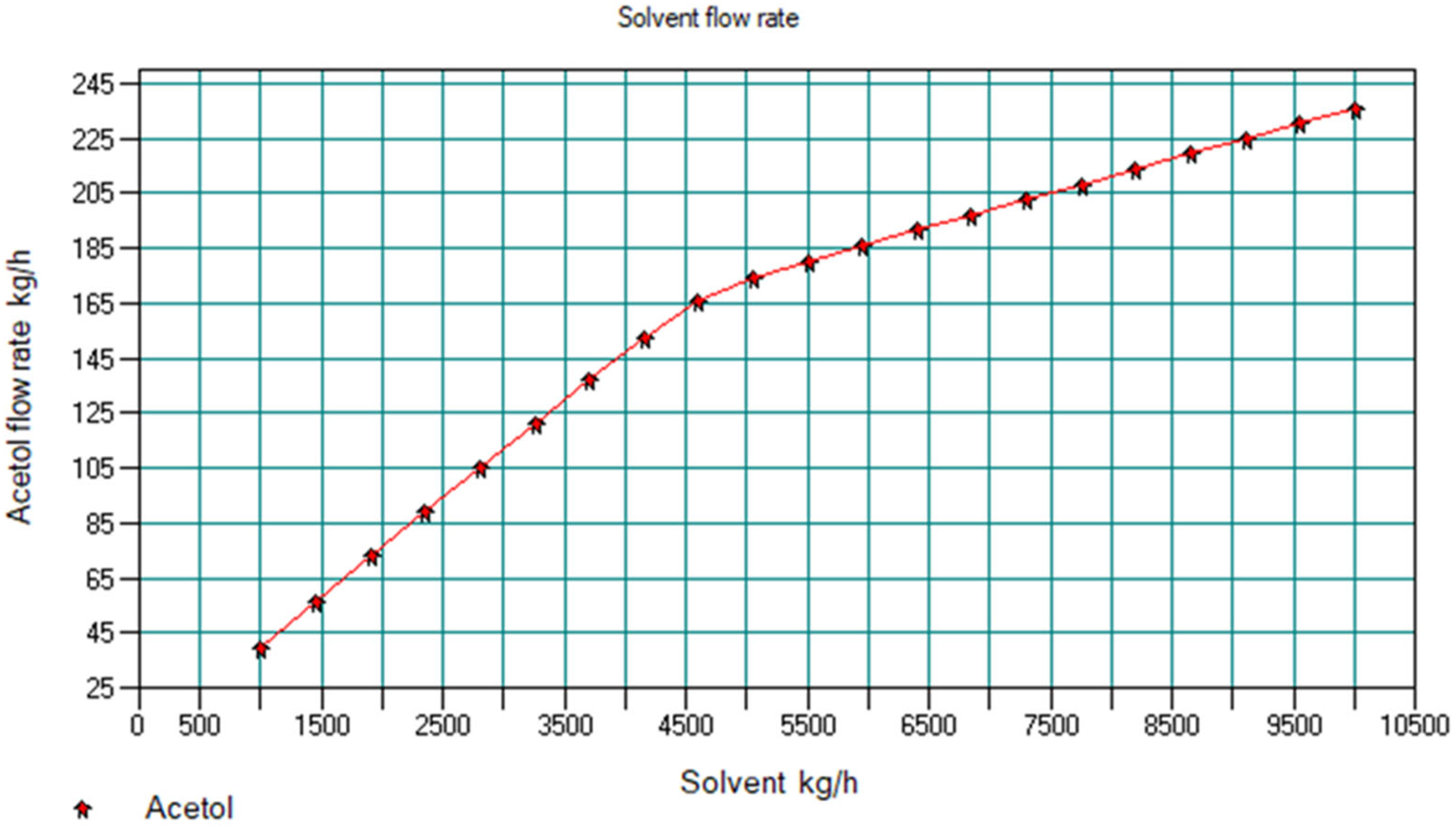
Figure 3 and Figure 4 show the results of the sensitivity analysis using tri-n-octylamine as an extractant. Figure 3 shows the acetol amount in the extract (stream 4 in Figure 2) as a function of solvent flow rate. Since a larger amount means higher losses, acetol is an undesirable component there.
Figure 4 shows the concentration of acetol in the raffinate (stream 3 in Figure 2) as a function of solvent flow rate. Since stream 3 represents the yield of pure acetol, the concentration of acetol in this stream should be at a maximum (greater than 99%).
Figure 3 and Figure 4 show that, by increasing the extractant flow rate, the purity of the upper-end product of column 1 (light phase) is improved while the amount of acetol in the heavy phase simultaneously increases. From the above, it can be concluded, for instance, that, for an optimal flow rate of tri-n-octylamine of 5000 kg·h−1, the amount of acetol in the lower-end product is 174.02 kg h−1, and the acetol concentration in the upper-end product is 99.41 wt%. Similar analyses were carried out for the other extractants used in this study. The results are summarised in Table 1.
As the toluene flow rate increases, the concentration of acetol in the extract increases, reaching a plateau with a maximum of 77.79 wt% of acetol. Since the desired purity of the acetol cannot be achieved with this extractant, it is unsuitable for use. The same applies to cyclohexane and n-heptane.
Table 1 shows that the best results are obtained with tri-n-octylamine and n-decane. Since tri-n-octylamine and n-decane require a flow rate of 5000 kg h−1 and 4400 kg h−1, respectively, n-decane proves to be more advantageous than tri-n-octylamine in that respect. Furthermore, the amount of acetol in the heavy phase (which has to be subsequently separated) is lower when n-decane is used. From this point of view, n-decane seems more appropriate. It can, however, be concluded that both solvents can be successfully used as extractants to separate the A/HAc system.
3.2. Acetic Acid Purification
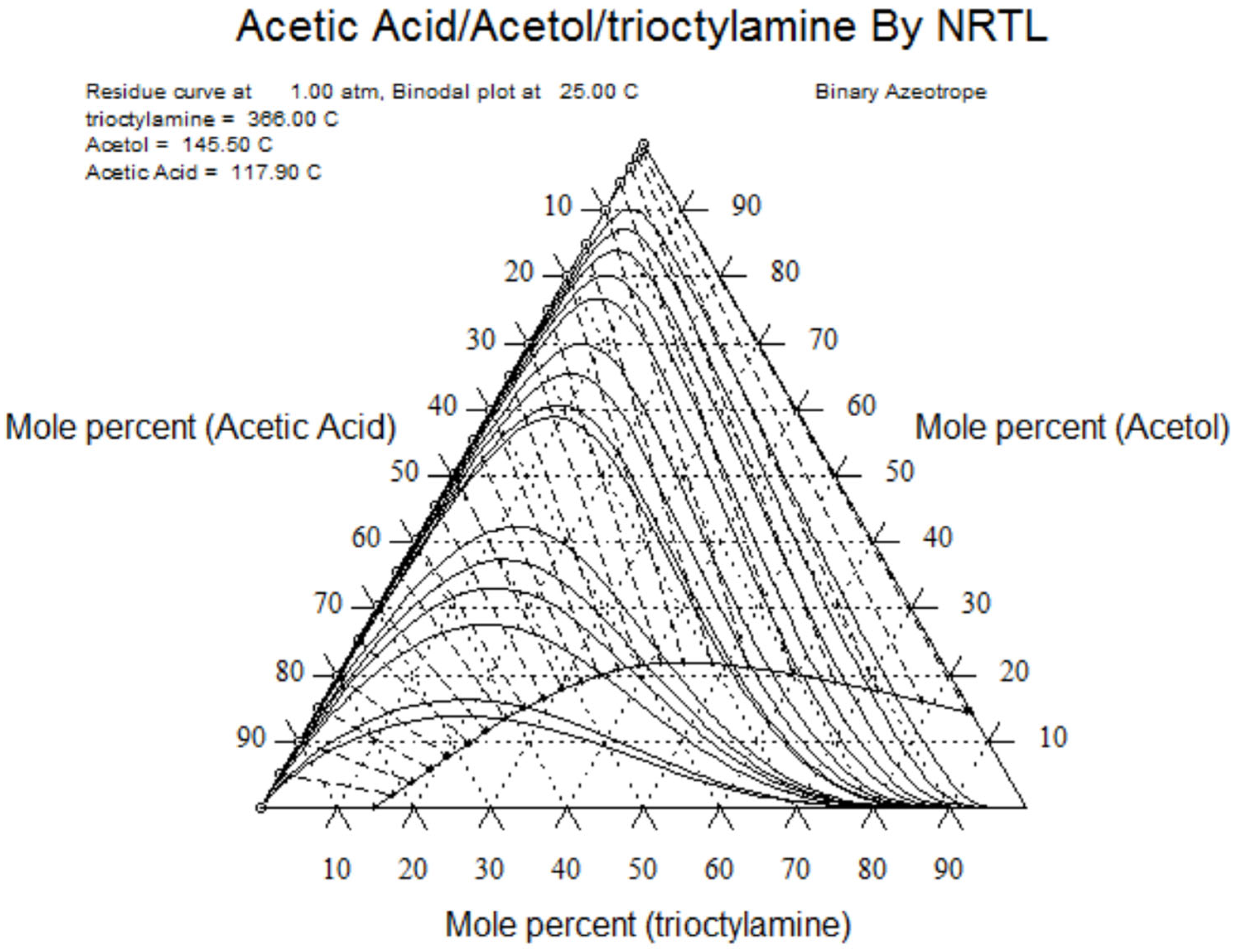
To regenerate the extractant, it is more convenient to use a distillation process. The possibility of regenerating the two selected extractants by distillation is discussed below. The equilibrium of the following ternary systems, tri-n-octylamine/A/HAc and n-decane/A/HAc, is modelled by the NRTL approach using the residual curve map topology. The general NRTL equation linking the activity coefficient to the molar concentrations of the different components is:
where
is a non-randomness parameter, and and are the temperature-dependent and temperature-independent binary interaction parameters, respectively.
Experimental equilibrium data for binary vapour–liquid equilibria were taken from the literature for the acetic acid/acetol system. For the other two systems, the binary equilibria were determined by the UNIFAC method. The coefficients are given in Table 2.
Results are shown in Figure 5 and Figure 6. From Figure 5, it can be seen that in the n-decane/A/HAc system, a double azeotrope is formed between n-decane and HAc. The composition of the azeotrope is 7.7 mol% n-decane and 92.3 mol% HAc with a boiling temperature of 115.78 °C. Since the boiling temperature of pure HAc is 117.9 °C, this azeotrope would accumulate in the distillate. As a result, the HAc obtained in the distillate would not be of sufficient purity. It is therefore not possible to separate HAc with a purity greater than 92.3 mol% using the conventional distillation process. Due to its inability to separate HAc, n-decane cannot be used as an extractant in this process.
Figure 6 shows that there is no such azeotrope in the octylamine/A/HAc system. It is therefore still possible to separate HAc from the extractant using a conventional distillation process.
3.2.1. Thermodynamic Equilibrium in Vapour–Liquid Systems
A correct modelling of the vapour–liquid equilibrium in the trioctylamine/A/HAc system is important for the final result. The classical UNIFAC method was selected to describe the VLE.
3.2.2. Production of Pure Acetic Acid
Pure acetic acid is produced in distillation column 2, whose primary requirement is to produce pure HAc as a distillate at its upper end. In addition, the concentration of HAc in the residue (at the lower end of the column) must be low enough to promote further purification of the extractant in column 3. The results of the numerical experiments show that the optimal number of stages is 20 and the optimal feed stage location is 17.
Composition profiles can be accessed after the simulation in each column configuration window. Figure 7 and Figure 8 show the concentration and temperature profiles in column 2 obtained after optimisation.
In order to optimise the performance of column 2, sensitivity studies were carried out by varying the reflux ratio and the vapour/bottom molar flow ratio. The best results obtained from these analyses are a reflux ratio of 5 and a vapour/bottom molar flow ratio of 2. Under these conditions, HAc with a purity of 100 wt% was obtained, whereas the residue from column 2 contains HAc (19.19 wt%), acetol (1.85 wt%), and tri-n-octylamine (78.95 wt%).
3.3. Extractant Regeneration
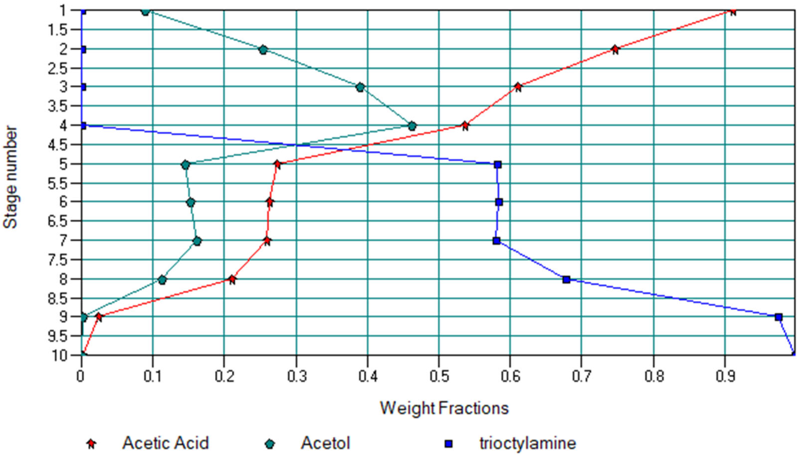
Before re-use, the extractant (tri-n-octylamine) must be purified from the residues of column 2, which also contain HAc and acetol. This occured in distillation column 3 (see Figure 2), where HAc (91.13 wt%) and acetol (8.87 wt%) were removed. After cooling in heat exchanger 5, this mixture was re-separated in column 1. Moreover, tri-n-octylamine was obtained as a residue of column 3 with a purity of 99.84 wt%. After cooling in heat exchanger 4 (stream 8), this purified extractant was returned to column 1 (stream 2).
Figure 9 and Figure 10 show the concentration and temperature profiles in column 3. It can be seen from Figure 9 that tri-n-octylamine accumulates at the top of the column. The concentration of the extractant down from the feed stage location (stage 5 in column 3 on Figure 2) decreases and, at the bottom of the column, reaches practically zero. Thus, practically 100% of the used tri-n-octylamine is regenerated.
In order to optimise the performance of this column, sensitivity analyses were carried out by varying the reflux ratio and the location of the feed stage. The optimal result obtained is 10 stages, a reflux ratio of 2, and a lower-end product temperature of 350 °C. The optimal location for the feed stage is 5. As a result, the treatment scheme designed for the separation of the A/HAc mixture is compact and ensures minimal equipment costs. The flowsheet is fed with the A/HAc mixture. The streams leaving the flowsheet are mostly acetol (99.4 wt%) and pure acetic acid (≈100 wt%). There is, therefore, no by-product waste. All intermediate flows are included in recycling and are 100% recovered. The energy optimisation of the designed flowsheet is beyond the scope of this study and is therefore not included in this article.
4. Conclusions
This study can be seen within the wider context of valorisation and biomass processing as the separation of a liquid mixture made up of components such as acetol and acetic acid shows, by extension, on the one hand, that molecules with high added value deserve to be identified and, on the other hand, that separating those molecules may still be possible using a hybrid process when individual processes fail.
In the present case, the hybrid process consisted of a combination of liquid–liquid extraction and distillation following a literature review of the possibilities for separating the liquid mixture so that their advantages could be combined, whereas their disadvantages could be minimised. The very fact that this process is based on a combination of techniques that are already well known also means that it can easily be applied on a large scale in industry. A flowsheet combining one liquid–liquid extraction column and two distillation columns was designed using the ChemCAD software and the NRTL and UNIFAC ‘LLE’ models were used to determine the thermodynamic equilibrium of the liquid mixtures. Sensitivity analyses were carried out to determine the key end-product parameters for all columns. The effect of different extractants and of their excess on the separation process, as well as the possibility of regenerating the extractant, was also studied. Tri-n-octylamine was accordingly selected as a separating agent that was fully recycled. As a final result, from the initial 48/52 wt% liquid mixture (2379 kg h−1), acetol (1132 kg h−1) with a purity of 99.4 wt% and acetic acid (1240.55 kg h−1) with a purity of 100 wt% were obtained.
Based on the predictive results of this study, experiments on real systems can be carried out to determine the thermodynamic equilibrium data and hence the parameters of the binary interactions in the tri-n-octylamine/acetol/acetic-acid system. Laboratory experiments would definitively validate the scheme proposed in this study. Beyond this system, this case study paves the way to a much broader research field.
Author Contributions
Conceptualization, C.C. and F.L.; methodology, C.C., P.L. and F.L.; software, C.C.; validation, C.C., P.L. and F.L.; investigation, F.L., C.C. and P.L.; writing—original draft preparation, C.C. and P.L.; writing—review, F.L. All authors have read and agreed to the published version of the manuscript.
Funding
The work presented in this article was funded by Project No. 12341 NIS-UCTM and has benefitted from Erasmus support between UCTM and Sorbonne Paris Nord University, as well as from the “Invited Fellow” protocol of Sorbonne Paris Nord University.
Data Availability Statement
All new data and results generated from this study are presented in the text of this publication.
Conflicts of Interest
The authors declare no conflict of interest.
References
- Muleta, N.; Badar, A.Q.H. Designing of an optimal standalone hybrid renewable energy micro-grid model through different algorithms. J. Eng. Res. 2023, 11, 100011. [Google Scholar] [CrossRef]
- Bafoil, F.; Dicko, M.; Guyet, R.; Lamari, F. Réflexions sur un référentiel commun entre sciences sociales et sciences de l’ingénieur en matière d’acceptation sociale des ouvrages éoliens. In L’énergie Éolienne en Europe. Conflits, Démocratie, Acceptabilité Sociale; Bafoil, F., Ed.; Presses de Sciences Po: Paris, France, 2016; pp. 253–283. [Google Scholar] [CrossRef]
- Cohen, M.; Lepesant, G.; Lamari, F.; Bilodeau, C.; Benyei, P.; Angles, S.; Bouillon, J.; Bourrand, K.; Landoulsi, R.; Jaboeuf, D.; et al. Biomolecules from olive pruning waste in Sierra Mágina. Engaging the energy transition by multi-actor and multidisciplinary analyses. J. Environ. Manag. 2018, 216, 204–213. [Google Scholar] [CrossRef]
- Dicko, M.; Ferrari, R.; Tangthirasunun, N.; Gautier, V.; Lalanne, C.; Lamari, F.; Silar, P. Lignin degradation and its use in signaling development by the coprophilous ascomycete Podospora anserina. J. Fungi 2020, 6, 278. [Google Scholar] [CrossRef]
- Do, H.T.; Bach, N.V.; Nguyen, L.V.; Tran, H.T.; Nguyen, M.T. A design of higher-level control based genetic algorithms for wastewater treatment plants. Eng. Sci. Technol. 2021, 24, 872–878. [Google Scholar] [CrossRef]
- Imam, T.; Capareda, S. Characterization of bio-oil, syn-gas and bio-char from switchgrass pyrolysis at various temperatures. J. Anal. Appl. Pyrol. 2012, 93, 170–177. [Google Scholar] [CrossRef]
- Hussany, F.L.; Jasim, D.J. Study of a feeding system for electric power plants using alternative fuels (energy emulsions). J. Eng. Res. 2023, 11, 219–226. [Google Scholar] [CrossRef]
- Grottola, C.M.; Giudicianni, P.; Stanzione, F.; Ragucci, R. Influence of Pyrolysis Temperature on Biochar Produced from Lignin–Rich Biorefinery Residue. ChemEngineering 2022, 6, 76. [Google Scholar] [CrossRef]
- Abejón, R. A Bibliometric Study of Scientific Publications regarding Hemicellulose Valorization during the 2000–2016 Period: Identification of Alternatives and Hot Topics. ChemEngineering 2018, 2, 7. [Google Scholar] [CrossRef]
- Mukarakate, C.; Evans, R.J.; Deutch, S.; Evans, T.; Starace, A.K.; Dam, J.; Watson, M.J.; Magrini, K. Reforming biomass derived pyrolysis bio-oil aqueous phase to fuels. Energy Fuels 2017, 31, 1600–1607. [Google Scholar] [CrossRef]
- Erdogdu, A.E.; Polat, R.; Ozbay, G. Pyrolysis of goat manure to produce bio-oil. Eng. Sci. Technol. 2019, 22, 452–457. [Google Scholar] [CrossRef]
- Li, J.; Lv, F.; Yang, R.; Zhang, L.; Tao, W.; Liu, G.; Gao, H.; Guan, Y. N-Doped Biochar from Lignocellulosic Biomass for Preparation of Adsorbent: Characterization, Kinetics and Application. Polymers 2022, 14, 3889. [Google Scholar] [CrossRef]
- Yang, C.; Wu, H.; Cai, M.; Zhou, Y.; Guo, C.; Han, Y.; Zhang, L. Valorization of Biomass-Derived Polymers to Functional Biochar Materials for Supercapacitor Applications via Pyrolysis: Advances and Perspectives. Polymers 2023, 15, 2741. [Google Scholar] [CrossRef]
- Infurna, G.; Caruso, G.; Dintcheva, N.T. Sustainable Materials Containing Biochar Particles: A Review. Polymers 2023, 15, 343. [Google Scholar] [CrossRef]
- Dicko, M.; Guilmont, M.; Lamari, F. Adsorption and biomass: Current interconnections and future challenges. Curr. Sustain. Renew. Energy Rep. 2018, 5, 247–256. [Google Scholar] [CrossRef]
- Pan, C.; Chen, A.; Liu, Z.; Chen, P.; Lou, H.; Zheng, X. Aqueous-phase reforming of the low-boiling fraction of rice husk pyrolyzed bio-oil in the presence of platinum catalyst for hydrogen production. Bioresour. Technol. 2012, 125, 335–339. [Google Scholar] [CrossRef]
- Ben, H.; Ferrell, J.R. In-depth investigation on quantitative characterization of pyrolysis oil by 31P NMR. RSC Adv. 2016, 6, 17567–17573. [Google Scholar] [CrossRef]
- Li, Y.; Ma, Q.; Li, G.; Lou, J.; Chen, X.; He, Y.; Peng, W.X. Pyrolysis of Aesculus chinensis Bunge Leaves as for Extracted Bio-Oil Material. Polymers 2022, 14, 5003. [Google Scholar] [CrossRef]
- Ben, H.; Wu, F.; Wu, Z.; Han, G.; Jiang, W.; Ragauskas, A.J. Comprehensive Characterization of Pyrolysis Oil from Softwood Barks. Polymers 2019, 11, 1387. [Google Scholar] [CrossRef]
- Mohan, D.; Pittman, C.U.; Steele, P.H. Pyrolysis of wood/biomass for bio-oil: A critical review. Energy Fuels 2006, 20, 848–889. [Google Scholar] [CrossRef]
- Oasmaa, A.; Meier, D. Norms and standards for fast pyrolysis liquids: 1. Round robin test. J. Anal. Appl. Pyrol. 2005, 73, 323–334. [Google Scholar] [CrossRef]
- Bertero, M.; de la Puente, G.; Sedran, U. Fuels from bio-oils: Bio-oil production from different residual sources, characterization and thermal conditioning. Fuel 2012, 95, 263–271. [Google Scholar] [CrossRef]
- Remon, J.; Broust, F.; Valette, J.; Chhiti, Y.; Alava, I.; Fernandez-Akarregi, A.R.; Arauzo, J.; Garcia, L. Production of a hydrogen-rich gas from fast pyrolysis bio-oils: Comparison between homogeneous and catalytic steam reforming routes. Int. J. Hydrogen Energy 2014, 39, 171–182. [Google Scholar] [CrossRef]
- Black, B.A.; Michener, W.E.; Ramirez, K.J.; Biddy, M.J.; Knott, B.C.; Jarvis, M.W.; Olstad, J.; Mante, O.D.; Dayton, D.C.; Beckham, G.T. Aqueous stream characterization from biomass fast pyrolysis and catalytic fast pyrolysis. ACS Sustain. Chem. Eng. 2016, 4, 6815–6827. [Google Scholar] [CrossRef]
- Sato, S.; Sakai, D.; Sato, F.; Yamada, Y. Vapor-phase dehydration of glycerol into hydroxyacetone over silver catalyst. Chem. Lett. 2012, 41, 965–966. [Google Scholar] [CrossRef]
- Hoyos, P.; Sinisterra, J.-V.; Molinari, F.; Alcántara, A.R.; de Maria, P.D. Biocatalytic strategies for the asymmetric synthesis of alpha-hydroxy ketones. Acc. Chem. Res. 2010, 43, 288–299. [Google Scholar] [CrossRef]
- Mohamad, M.H.; Awang, R.; Yunus, W. A review of acetol: Application and production. Am. J. Appl. Sci. 2011, 8, 1135–1139. [Google Scholar] [CrossRef]
- Kramar, A.; González-Benito, J. Preparation of cellulose acetate film with dual hydrophobic-hydrophilic properties using solution blow spinning. Mater. Des. 2023, 227, 111788. [Google Scholar] [CrossRef]
- Pérez-Nava, A.; Reyes-Mercado, E.; González-Campos, J.B. Production of chitosan nanofibers using the HFIP/acetic acid mixture as electrospinning solvent. Chem. Eng. Process. 2022, 173, 108849. [Google Scholar] [CrossRef]
- Jia, X.; Guo, D.; Yan, Q.; Yu, H.; Lyu, Q.; Han, L.; Zhou, C.; Xiao, W. Synthesis and Characterization of Corn Stover-Based Cellulose Triacetate Catalyzed by Ionic Liquid Phosphotungstate. Int. J. Mol. Sci. 2022, 23, 6783. [Google Scholar] [CrossRef]
- Zhang, J.; Xu, W.-R.; Zhang, Y.-C. Facile production of chitin from shrimp shells using a deep eutectic solvent and acetic acid. RSC Adv. 2022, 12, 22631–22638. [Google Scholar] [CrossRef]
- Sun, T.; Zhang, J.; Zhang, Q.; Li, X.; Li, M.; Yang, Y.; Zhou, J.; Wei, Q.; Zhou, B. Exogenous application of acetic acid enhances drought tolerance by influencing the MAPK signaling pathway induced by ABA and JA in apple plants. Tree Physiol. 2022, 42, 1827–1840. [Google Scholar] [CrossRef]
- Mora, M.; Fàbregas, E.; Céspedes, F.; Rovira, P.; Puy, N. Dialysis and column chromatography for biomass pyrolysis liquids separation. Waste Manag. 2023, 168, 311–320. [Google Scholar] [CrossRef]
- Bridgwater, A.V. The production of biofuels and renewable chemicals by fast pyrolysis of biomass. Int. J. Glob. Energy 2007, 27, 160–203. [Google Scholar] [CrossRef]
- Cerqueira, S.C.; Santos, L.M.; Gois, A.R.; Soares, C.M.; DaSilveira Neto, B.A.; Freitas, L.S. Use of Ionic Liquid-Based Ultrasound Assisted Liquid-Liquid Extraction of Phenols from Aqueous Fractions of Seed Bio-Oil. J. Brazil. Chem. Soc. 2023, 34, 725–733. [Google Scholar] [CrossRef]
- Mungma, N.; Kienberger, M.; Siebenhofer, M. Reactive extraction of lactic acid, formic acid and acetic acid from aqueous solutions with tri-n-octylamine/1-octanol/n-undecane. ChemEngineering 2019, 3, 43. [Google Scholar] [CrossRef]
- Kumar, A.; Raghuwanshi, S.S.; Lall Pal, S. Extractive Separation of Acetic Acid from Aqueous Solution using Tertiary Amine + Biodiesels at 298 K. In Proceedings of the International Conference on “Recent Advances in Interdisciplinary Trends in Engineering & Applications” (RAITEA), Indore, India, 14–16 February 2019. [Google Scholar] [CrossRef]
- Mahfud, F.H.; van Geel, F.P.; Venderbosch, R.H.; Heeres, H.J. Acetic acid recovery from fast pyrolysis oil. An exploratory study on liquid-liquid reactive extraction using aliphatic tertiary amines. Sep. Sci. Technol. 2008, 43, 3056–3074. [Google Scholar] [CrossRef]
- Westerhof, R.J.M.; Brilman, D.W.F.; Garcia-Perez, M.; Wang, Z.; Oudenhoven, S.R.G.; van Swaaij, W.P.M.; Kersten, S.R.A. Fractional condensation of biomass pyrolysis vapors. Energy Fuels 2011, 25, 1817–1829. [Google Scholar] [CrossRef]
- Lam, S.S.; Yek, P.N.Y.; Ok, Y.S.; Chong, C.C.; Liew, R.K.; Tsang, D.C.W.; Park, Y.-K.; Liu, Z.; Wong, C.S.; Peng, W. Engineering pyrolysis biochar via single-step microwave steam activation for hazardous landfill leachate treatment. J. Hazard. Mater. 2020, 390, 121649. [Google Scholar] [CrossRef]
- Naik, S.; Goud, V.V.; Rout, P.K.; Dalai, A.K. Supercritical CO2 fractionation of bio-oil produced from wheat-hemlock biomass. Bioresour. Technol. 2010, 101, 7605–7613. [Google Scholar] [CrossRef]
- Bruns, B.; Fasel, H.; Grünewald, M.; Riese, J. Development of a Dynamic Modeling Approach to Simulate a Segmented Distillation Column for Flexible Operation. ChemEngineering 2021, 5, 66. [Google Scholar] [CrossRef]
- Tsirlin, A.; Sukin, I.; Balunov, A. Selection of Optimum Separation Sequence for Multicomponent Distillation. ChemEngineering 2019, 3, 69. [Google Scholar] [CrossRef]
- ChemCAD User Guide. 2021. Available online: https://www.chemstations.com/content/documents/CHEMCAD_User_Guide.pdf (accessed on 1 May 2023).
- Fredenslund, A.; Jones, R.L.; Prausnitz, J.M. Group-contribution estimation of activity coefficients in non-ideal liquid mixtures. AIChE J. 1975, 21, 1086–1099. [Google Scholar] [CrossRef]
- Fredenslund, A.; Gmehling, J.; Rasmussen, P. The Unifac Group-Contribution Method. In Vapor-Liquid Equilibria Using Unifac; Elsevier: Amsterdam, The Netherlands, 1977; pp. 27–64. [Google Scholar] [CrossRef]
- Magnussen, T.; Rasmussen, P.; Fredenslund, A. UNIFAC Parameter Table for Prediction of Liquid-liquid Equilibria. Ind. Eng. Chem. Process Des. Dev. 1981, 20, 331–339. [Google Scholar] [CrossRef]
- Rasrendra, C.B.; Girisuta, B.; van de Bovenkamp, H.H.; Winkelman, J.G.M.; Leijenhorst, E.J.; Venderbosch, R.H.; Windt, M.; Meier, D.; Heeres, H.J. Recovery of acetic acid from an aqueous pyrolysis oil phase by reactive extraction using tri-n-octylamine. Chem. Eng. J. 2011, 176, 244–252. [Google Scholar] [CrossRef]
- Hong, Y.K.; Hong, W.H. Removal of acetic acid from aqueous solutions containing succinic acid and acetic acid by tri-n-octylamine. Sep. Purif. Technol. 2005, 42, 151–157. [Google Scholar] [CrossRef]
- Keshav, A.; Wasewar, K.L.; Chand, S. Extraction of propionic acid with tri-n-octyl amine in different diluents. Sep. Purif. Technol. 2008, 63, 179–183. [Google Scholar] [CrossRef]
- Chien, I.L.; Zeng, K.L.; Chao, H.Y.; Liu, J.H. Design and control of acetic acid dehydration system via heterogeneous azeotropic distillation. Chem. Eng. Sci. 2004, 59, 4547–4567. [Google Scholar] [CrossRef]
- Stephan, C.; Dicko, M.; Stringari, P.; Coquelet, C. Liquid-liquid equilibria of water + solutes (acetic acid/acetol/furfural/guaiacol/methanol/phenol/propanal) + solvents (isopropyl acetate/toluene) ternary systems for pyrolysis oil fractionation. Fluid Phase Equilibr. 2018, 468, 49–57. [Google Scholar] [CrossRef]
Figure 1.
Equilibrium data for the A/HAc system.

Figure 2.
Flowsheet for A/HAc separation.

Figure 3.
Acetol amount in the extract as a function of solvent flow rate.

Figure 4.
Acetol concentration in the raffinate as a function of solvent flow rate.

Figure 5.
Equilibrium predicted for the n-decane/A/HAc system.

Figure 6.
Equilibrium predicted for the tri-n-octylamine/A/HAc system.

Figure 7.
Tray liquid concentration profile in column 2.

Figure 8.
Tray temperature profile in column 2.

Figure 9.
Tray concentration profile in column 3.

Figure 10.
Tray temperature profile in column 3.


Table 1.
Numerical experiment results for an initial composition of A/HAc of 50–50 mol%.
| Solvent | Optimal Solvent Flow Rate (kg h−1) | Upper-End Acetol Fraction (wt%) | Lower-End Acetol Flow Rate (kg h−1) |
|---|---|---|---|
| di-n-octylether CAS 629-82-3 | 3200 | 99.46 | 155.12 |
| tri-n-octylamine CAS 1116-76-3 | 5000 | 99.41 | 174.02 |
| tri-n-butylamine CAS 102-82-9 | 3300 | 99.02 | 201.14 |
| cyclohexane CAS 110-82-7 | 4000 | 95.89 | 97.35 |
| tri-n-pentylamine CAS 621-77-2 | 3700 | 99.12 | 140.56 |
| toluene CAS 108-88-3 | 6800 | 77.79 | 212.63 |
| n-heptane CAS 142-82-5 | 4200 | 98.21 | 82.76 |
| n-decane CAS 124-18-5 | 4400 | 99.01 | 61.20 |
Table 2.
Binary interaction parameters for the NRTL model.
| System | Source | |||||
|---|---|---|---|---|---|---|
| tri-n-octylamine/acetic acid | 0 | 0 | 2099.406 | −411.6049 | 0.3998 | UNIFAC |
| acetic acid/acetol | 0.531 | −1.732 | −543.900 | 1326.0000 | 0.3000 | Ch. Stephan et al. [52] |
| tri-n-octylamine/acetol | 0 | 0 | 2499.792 | 196.9379 | 0.2000 | UNIFAC |
Disclaimer/Publisher’s Note: The statements, opinions and data contained in all publications are solely those of the individual author(s) and contributor(s) and not of MDPI and/or the editor(s). MDPI and/or the editor(s) disclaim responsibility for any injury to people or property resulting from any ideas, methods, instructions or products referred to in the content. |
© 2023 by the authors. Licensee MDPI, Basel, Switzerland. This article is an open access article distributed under the terms and conditions of the Creative Commons Attribution (CC BY) license (https://creativecommons.org/licenses/by/4.0/).
Share and Cite
MDPI and ACS Style
Chilev, C.; Lamari, F.; Langlois, P. Numerical Simulation of a Valorisation-Oriented Hybrid Process for the Bio-Oil-Related Separation of Acetol and Acetic Acid. ChemEngineering 2024, 8, 5. https://doi.org/10.3390/chemengineering8010005
AMA Style
Chilev C, Lamari F, Langlois P. Numerical Simulation of a Valorisation-Oriented Hybrid Process for the Bio-Oil-Related Separation of Acetol and Acetic Acid. ChemEngineering. 2024; 8(1):5. https://doi.org/10.3390/chemengineering8010005
Chicago/Turabian StyleChilev, Chavdar, Farida Lamari, and Patrick Langlois. 2024. "Numerical Simulation of a Valorisation-Oriented Hybrid Process for the Bio-Oil-Related Separation of Acetol and Acetic Acid" ChemEngineering 8, no. 1: 5. https://doi.org/10.3390/chemengineering8010005