
A Comparison of In Vivo Bone Tissue Generation Using Calcium Phosphate Bone Substitutes in a Novel 3D Printed Four-Chamber Periosteal Bioreactor
 , , , , , , , , , and
Abstract
:
1. Introduction
2. Materials and Methods
2.1. Design of the Four-Chambered Bioreactors
2.2. Additive Manufacturing of PEEK Bioreactors
2.3. Plasma Immersion Ion Implantation Treatment of PEEK Bioreactors
2.4. Implantation Surgery
2.5. MicroCT Scanning and Analysis of the Harvested PEEK Bioreactor Contents
2.6. Histology
2.7. Statistical Analysis
3. Results
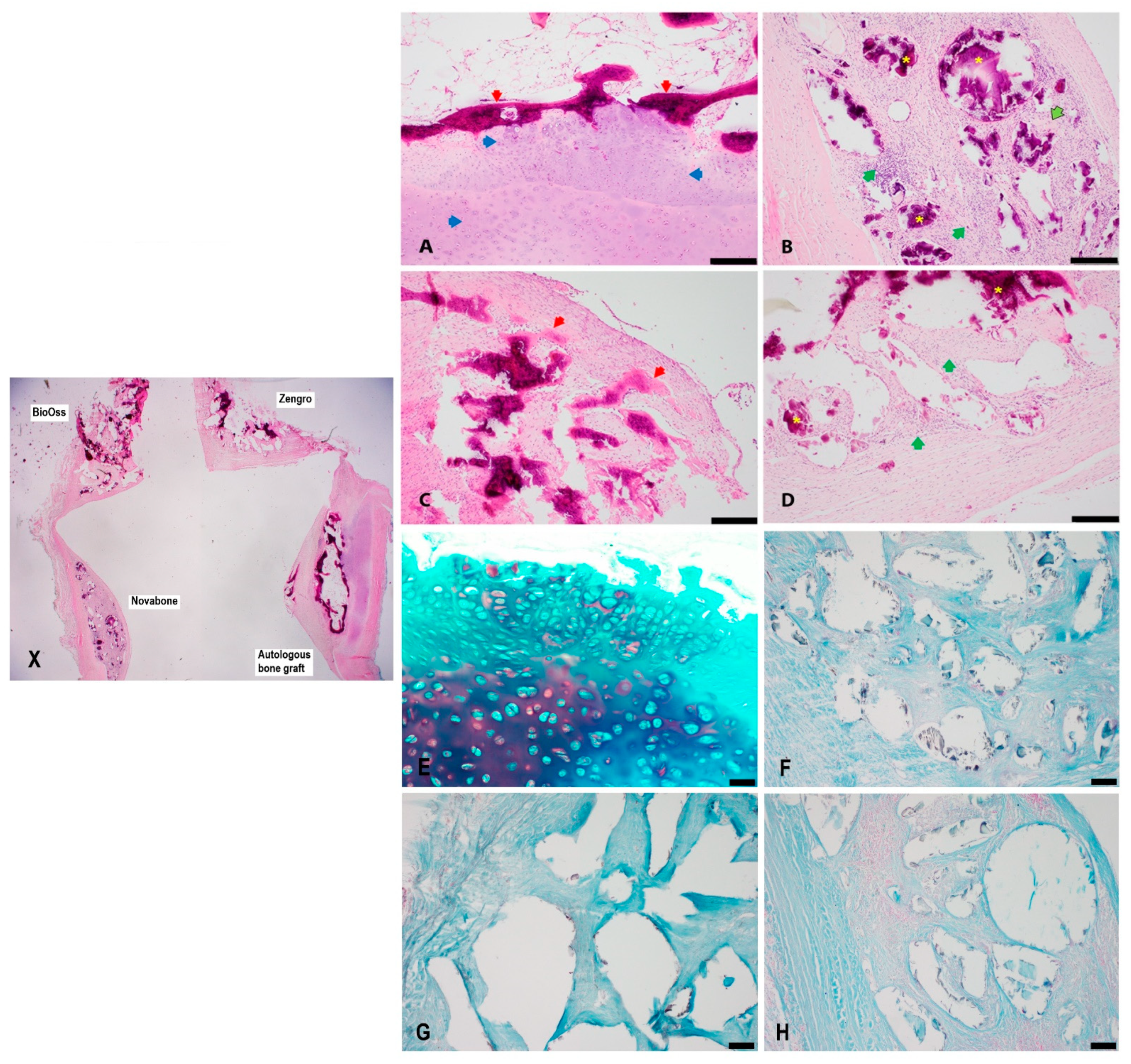
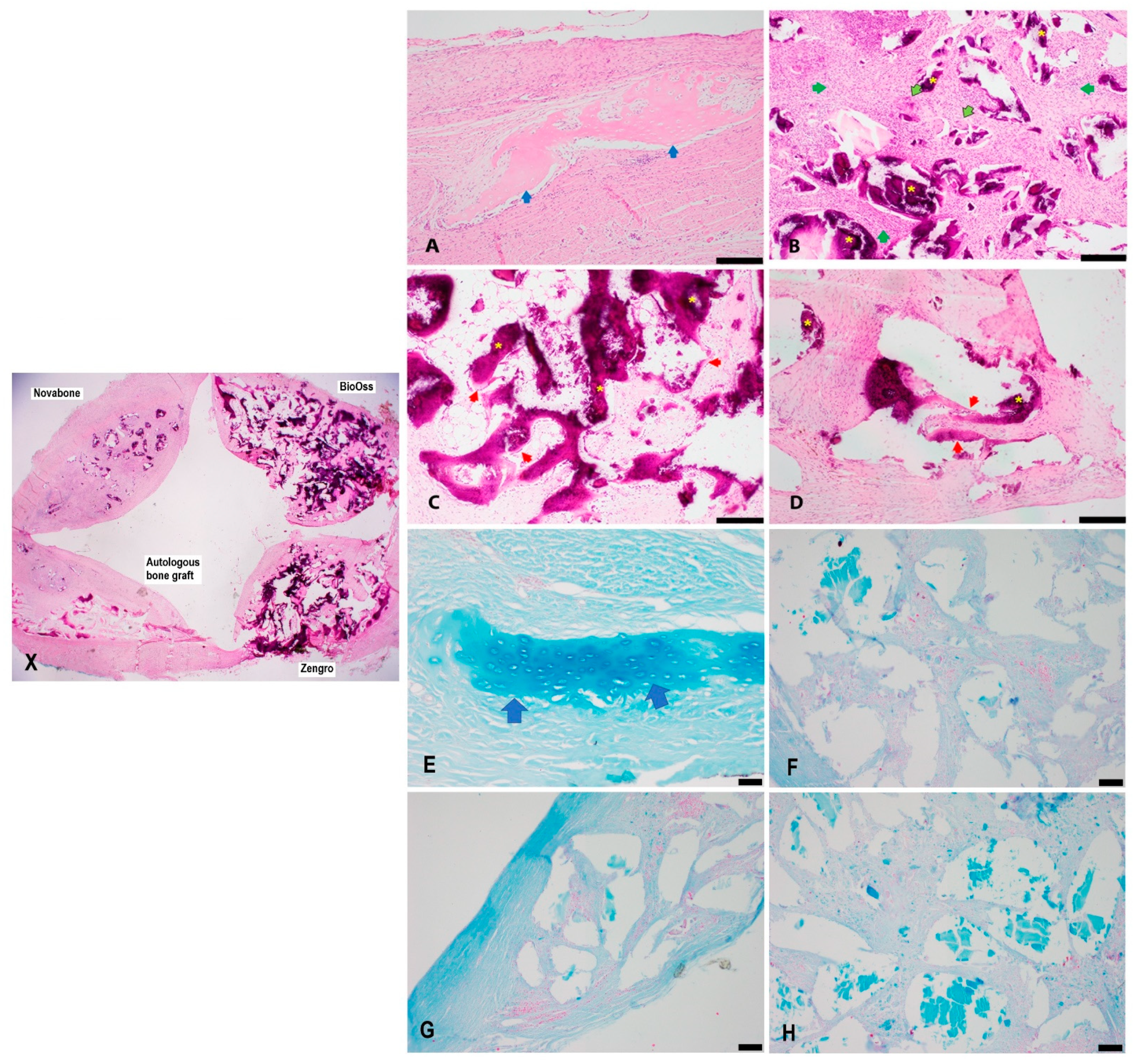
3.1. Histology
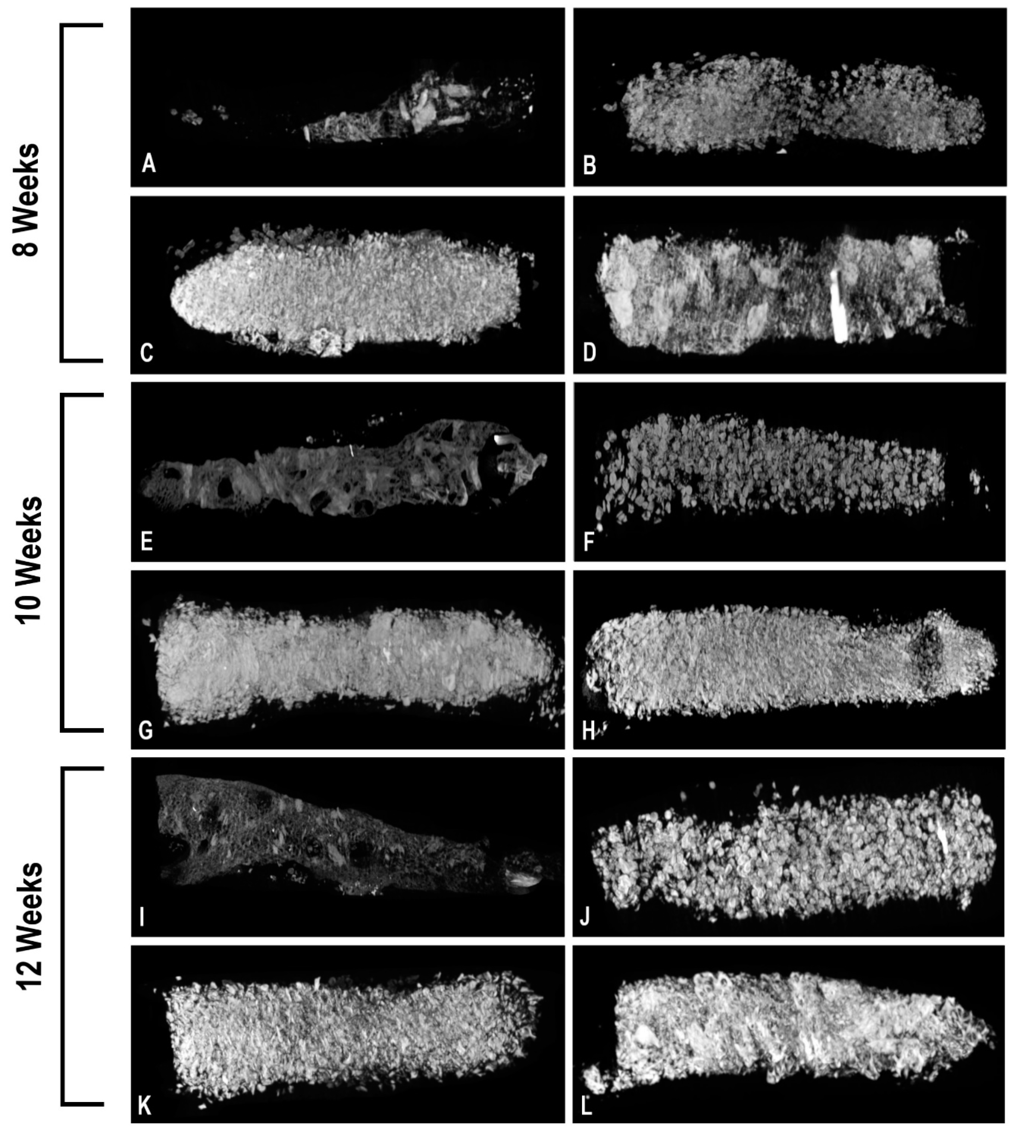
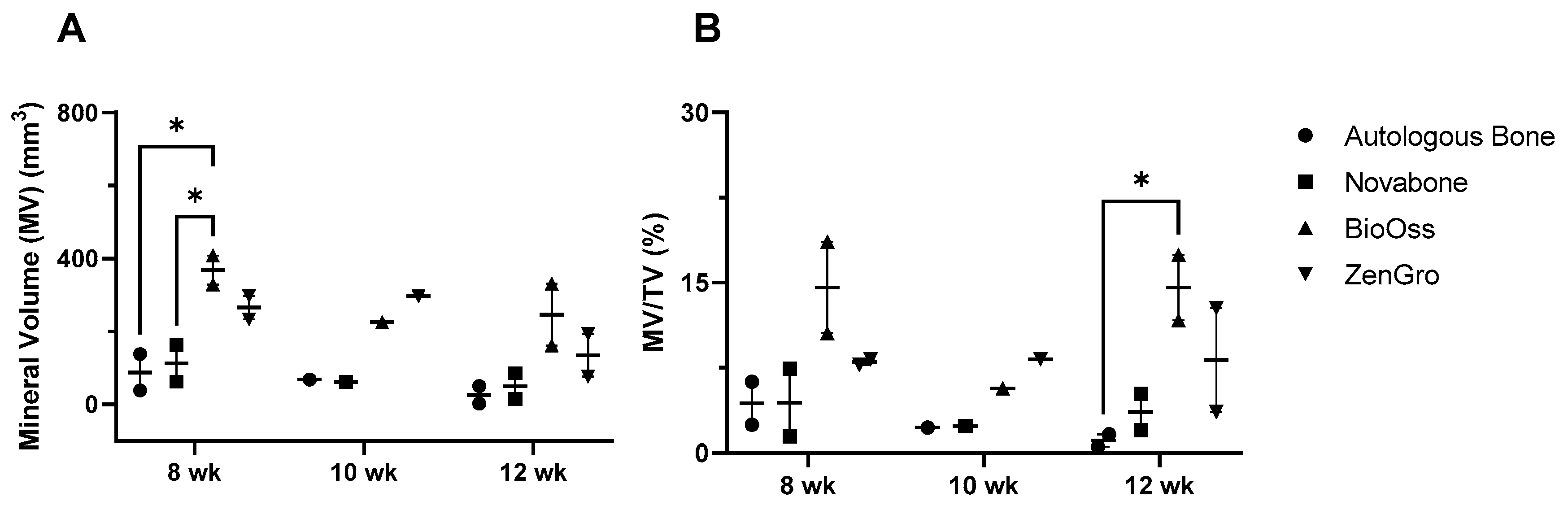
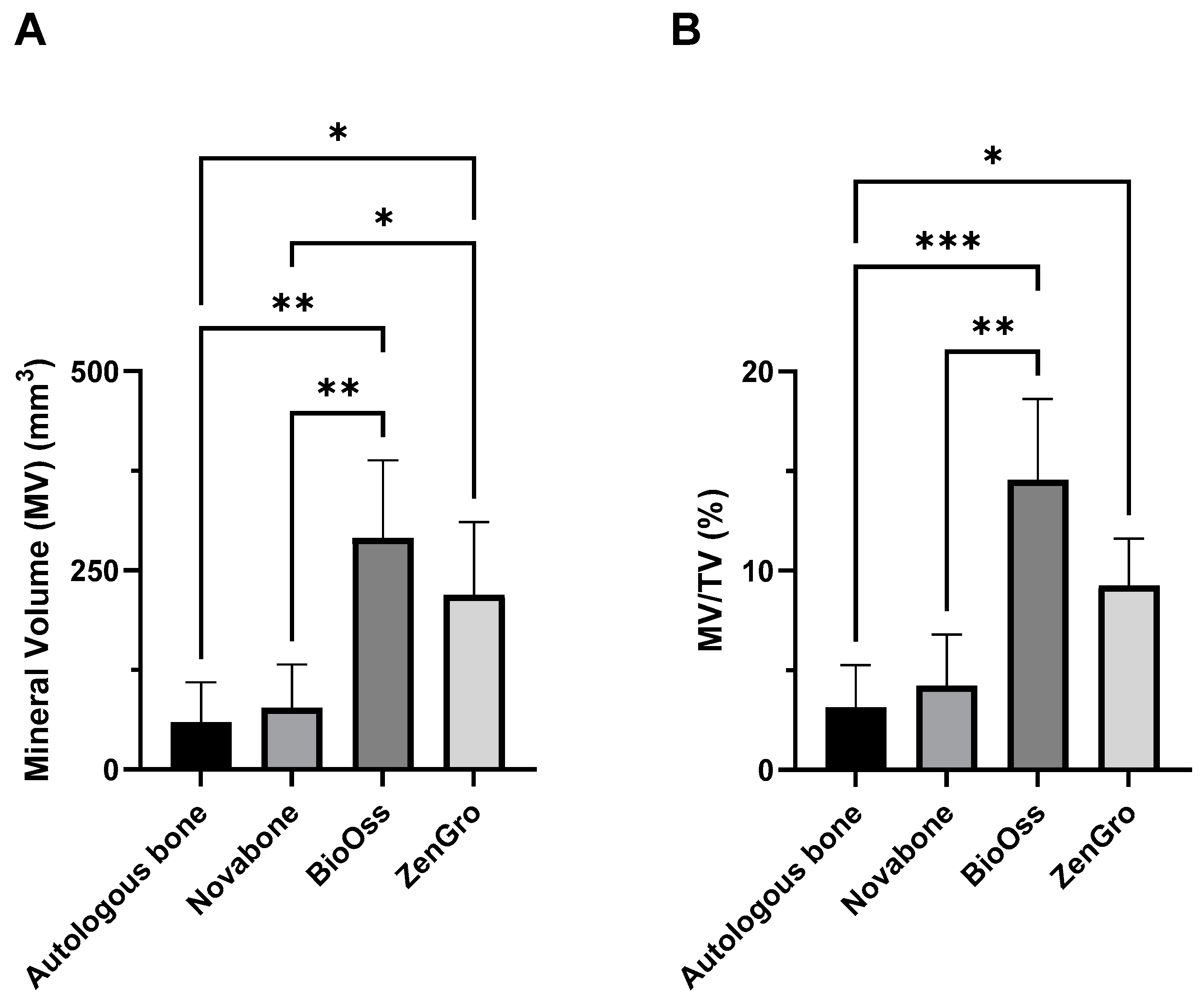
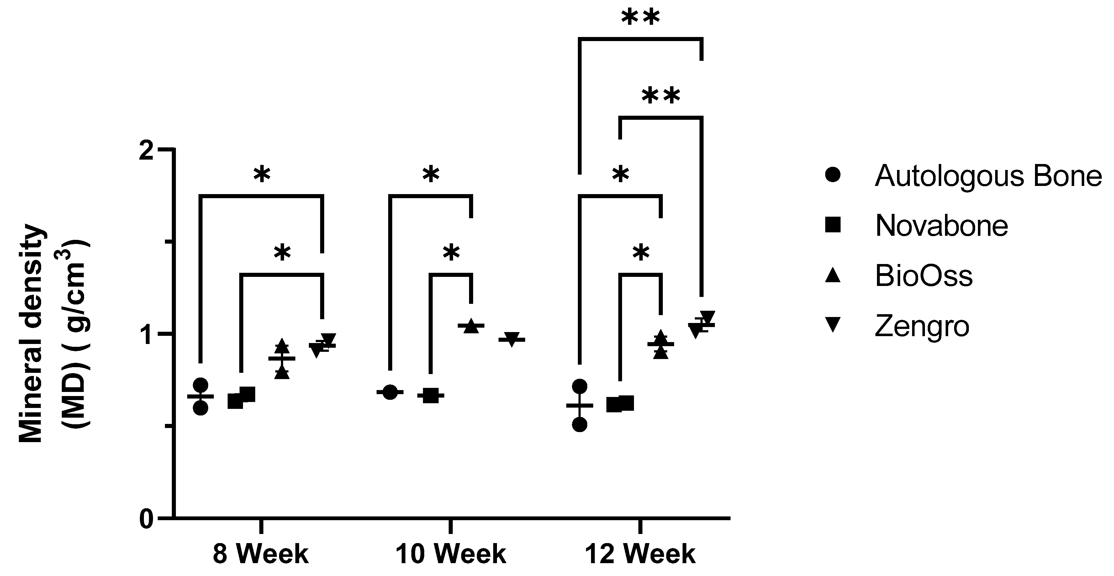
3.2. microCT Analysis of the Bioreactor Contents
4. Discussion
5. Conclusions
Supplementary Materials
Author Contributions
Funding
Institutional Review Board Statement
Data Availability Statement
Acknowledgments
Conflicts of Interest
Abbreviations
| 3D | Three dimensional |
| PIII | Plasma immersion ion implantation |
| PEEK | Polyether ether ketone |
| BTE | Bone tissue engineering |
| BMP-2 | Bone morphogenetic protein-2 |
| PRF | Platelet-rich fibrin |
| NBF | Neutral buffered formalin |
| microCT | micro computed tomography |
| TV | Total tissue volume |
| MV | Mineral volume |
| MV/TV | Mineral volume–total tissue volume ratio |
| MD | Mineral density |
| HU | Hounsfield units |
| H&E | Hematoxylin and eosin |
References
- Al Maruf, D.S.A.; Parthasarathi, K.; Cheng, K.; Mukherjee, P.; McKenzie, D.R.; Crook, J.M.; Wallace, G.G.; Clark, J.R. Current and Future Perspectives on Biomaterials for Segmental Mandibular Defect Repair. Int. J. Polym. Mater. Polym. Biomater. 2022, 72, 725–737. [Google Scholar] [CrossRef]
- Hickey, A.J.; Salter, M. Prosthodontic and Psychological Factors in Treating Patients with Congenital and Craniofacial Defects. J. Prosthet. Dent. 2006, 95, 392–396. [Google Scholar] [CrossRef]
- Macgregor, F.C. Facial Disfigurement: Problems and Management of Social Interaction and Implications for Mental Health. Aesthetic Plast. Surg. 1990, 14, 249–257. [Google Scholar] [CrossRef] [PubMed]
- Al Maruf, D.S.A.; Ghosh, Y.A.; Xin, H.; Cheng, K.; Mukherjee, P.; Crook, J.M.; Wallace, G.G.; Klein, T.J.; Clark, J.R. Hydrogel: A Potential Material for Bone Tissue Engineering Repairing the Segmental Mandibular Defect. Polymers 2022, 14, 4186. [Google Scholar] [CrossRef] [PubMed]
- Henkel, J.; Woodruff, M.A.; Epari, D.R.; Steck, R.; Glatt, V.; Dickinson, I.C.; Choong, P.F.M.; Schuetz, M.A.; Hutmacher, D.W. Bone Regeneration Based on Tissue Engineering Conceptions—A 21st Century Perspective. Bone Res. 2013, 3, 216–248. [Google Scholar] [CrossRef]
- Dinopoulos, H.T.H.; Giannoudis, P. V Safety and Efficacy of Use of Demineralised Bone Matrix in Orthopaedic and Trauma Surgery. Expert Opin. Drug Saf. 2006, 5, 847–866. [Google Scholar] [CrossRef]
- Bostrom, M.P.G.; Seigerman, D.A. The Clinical Use of Allografts, Demineralized Bone Matrices, Synthetic Bone Graft Substitutes and Osteoinductive Growth Factors: A Survey Study. HSS J. 2005, 1, 9–18. [Google Scholar] [CrossRef]
- Katz, J.M.; Nataraj, C.; Jaw, R.; Deigl, E.; Bursac, P. Demineralized Bone Matrix as an Osteoinductive Biomaterial and In Vitro Predictors of Its Biological Potential. J. Biomed. Mater. Res.-Part B Appl. Biomater. 2009, 89, 127–134. [Google Scholar] [CrossRef]
- Katsifis, G.; Kruse, H.; Lewin, W.; Al Maruf, A.; Clark, J.R.; McKenzie, D.R.; Suchowerska, N. Micro-CT Analysis of Implanted Poly-Ether-Ether-Ketone (PEEK) Scaffolds: Plasma Immersion Ion Implantation Increases Osteoconduction. Adv. Eng. Mater. 2023, 25, 2201297. [Google Scholar] [CrossRef]
- Kruse, H.V.; Lewin, W.T.; Suchowerska, N.; Al Maruf, D.S.A.; Cheng, K.; Clark, J.R.; McKenzie, D.R. Plasma Immersion Ion-Implanted 3D-Printed PEEK Bone Implants: In Vivo Sheep Study Shows Strong Osseointegration. Plasma Process. Polym. 2022, 19, 2100244. [Google Scholar] [CrossRef]
- Kruse, H.V.; McKenzie, D.R.; Clark, J.R.; Suchowerska, N. Plasma Ion Implantation of 3D-Printed PEEK Creates Optimal Host Conditions for Bone Ongrowth and Mineralisation. Plasma Process. Polym. 2021, 18, 2000219. [Google Scholar] [CrossRef]
- Ewers, R. Maxilla Sinus Grafting with Marine Algae Derived Bone Forming Material: A Clinical Report of Long-Term Results. J. Oral Maxillofac. Surg. 2005, 63, 1712–1723. [Google Scholar] [CrossRef] [PubMed]
- Tadic, D.; Epple, M. A Thorough Physicochemical Characterisation of 14 Calcium Phosphate-Based Bone Substitution Materials in Comparison to Natural Bone. Biomaterials 2004, 25, 987–994. [Google Scholar] [CrossRef] [PubMed]
- Matusovits, D.; Suba, Z.; Takács, D.; Turzó, K.; Donath, K.; Fazekas, A. A Pilot Study of Cerasorb and Bio-Oss Enhanced New Bone Formation in Animal Model. Acta Biol. Hung. 2008, 59, 327–334. [Google Scholar] [CrossRef] [PubMed]
- Yang, C.; Liu, Y.; Li, C.; Zhang, B. Repair of Mandibular Defects by Bone Marrow Stromal Cells Expressing the Basic Fibroblast Growth Factor Transgene Combined with Multi-Pore Mineralized Bio-Oss. Mol. Med. Rep. 2013, 7, 99–104. [Google Scholar] [CrossRef]
- Fontana, F.; Rocchietta, I.; Dellavia, C.; Nevins, M.; Simion, M. Biocompatibility and Manageability of a New Fixable Bone Graft for the Treatment of Localized Bone Defects: Preliminary Study in a Dog Model. Int. J. Periodontics Restor. Dent. 2008, 28, 601–607. [Google Scholar]
- Camelo, M.; Nevins, M.; Lynch, S.; Schenk, R.; Simion, M.; Nevins, M. Periodontal Regeneration with an Autogenous Bone-Bio-Oss Composite Graft and a Bio-Gide Membrane. Int. J. Periodontics Restor. Dent. 2001, 21, 109–119. [Google Scholar]
- Tadjoedin, E.S.; De Lange, G.L.; Bronckers, A.L.J.J.; Lyaruu, D.M.; Burger, E.H. Deproteinized Cancellous Bovine Bone (Bio-Oss®) as Bone Substitute for Sinus Floor Elevation. A Retrospective, Histomorphometrical Study of Five Cases. J. Clin. Periodontol. 2003, 30, 261–270. [Google Scholar] [CrossRef]
- Wei, Y.; Zhu, G.; Zhao, Z.; Yin, C.; Zhao, Q.; Xu, H.; Wang, J.; Zhang, J.; Zhang, X.; Zhang, Y.; et al. Individualized Plasticity Autograft Mimic with Efficient Bioactivity Inducing Osteogenesis. Int. J. Oral Sci. 2021, 13, 14. [Google Scholar] [CrossRef]
- Kargarpour, Z.; Nasirzade, J.; Panahipour, L.; Mitulović, G.; Miron, R.J.; Gruber, R. Platelet-Rich Fibrin Increases Bmp2 Expression in Oral Fibroblasts via Activation of Tgf-β Signaling. Int. J. Mol. Sci. 2021, 22, 7935. [Google Scholar] [CrossRef]
- Landi, E.; Celotti, G.; Logroscino, G.; Tampieri, A. Carbonated Hydroxyapatite as Bone Substitute. J. Eur. Ceram. Soc. 2003, 23, 2931–2937. [Google Scholar] [CrossRef]
- Lin, Z.; Fateh, A.; Salem, D.M.; Intini, G. Periosteum: Biology and Applications in Craniofacial Bone Regeneration. J. Dent. Res. 2014, 93, 109–116. [Google Scholar] [CrossRef] [PubMed]
- Huang, R.L.; Tremp, M.; Ho, C.K.; Sun, Y.; Liu, K.; Li, Q. Prefabrication of a Functional Bone Graft with a Pedicled Periosteal Flap as an in Vivo Bioreactor. Sci. Rep. 2017, 7, 18038. [Google Scholar] [CrossRef] [PubMed]
- Holt, G.E.; Halpern, J.L.; Dovan, T.T.; Hamming, D.; Schwartz, H.S. Evolution of an in Vivo Bioreactor. J. Orthop. Res. 2005, 23, 916–923. [Google Scholar] [CrossRef] [PubMed]
- Tatara, A.M.; Shah, S.R.; Demian, N.; Ho, T.; Shum, J.; van den Beucken, J.; Jansen, J.A.; Wong, M.E.; Mikos, A.G. Reconstruction of Large Mandibular Defects Using Autologous Tissues Generated from in Vivo Bioreactors. Acta Biomater. 2016, 45, 72–84. [Google Scholar] [CrossRef]
- Barbara, Y.; Woodford, P.; O’Dowd, G. Wheater’s Functional Histology: A Text and Colour Atlas, 6th ed.; Churchill Livingstone: London, UK, 2013. [Google Scholar]
- Stacey, M. Histology for Pathologists, 5th ed.; Lippincott Williams & Wilkins: Philadelphia, PA, USA, 2019. [Google Scholar]
- Lee, Y.C.; Chan, Y.H.; Hsieh, S.C.; Lew, W.Z.; Feng, S.W. Comparing the Osteogenic Potentials and Bone Regeneration Capacities of Bone Marrow and Dental Pulp Mesenchymal Stem Cells in a Rabbit Calvarial Bone Defect Model. Int. J. Mol. Sci. 2019, 20, 5015. [Google Scholar] [CrossRef]
- Jeong, J.; Kim, J.H.; Shim, J.H.; Hwang, N.S.; Heo, C.Y. Bioactive Calcium Phosphate Materials and Applications in Bone Regeneration. Biomater. Res. 2019, 23, 1–11. [Google Scholar] [CrossRef]
- Koempel, J.A.; Patt, B.S.; O’Grady, K.; Wozney, J.; Toriumi, D.M. The Effect of Recombinant Human Bone Morphogenetic Protein-2 on the Integration of Porous Hydroxyapatite Implants with Bone. J. Biomed. Mater. Res. 1998, 41, 359–363. [Google Scholar] [CrossRef]
- Piattelli, M.; Favero, G.A.; Scarano, A.; Orsini, G.; Piattelli, A. Bone Reactions to Anorganic Bovine Bone (Bio-Oss) Used in Sinus Augmentation Procedures: A Histologic Long-Term Report of 20 Cases in Humans. Int. J. Oral Maxillofac. Implants 2000, 14, 835–840. [Google Scholar]
- Liljensten, E.; Adolfsson, E.; Strid, K.G.; Thomsen, P. Resorbable and Nonresorbable Hydroxyapatite Granules as Bone Graft Substitutes in Rabbit Cortical Defects. Clin. Implant Dent. Relat. Res. 2003, 5, 95–102. [Google Scholar] [CrossRef]
- Dennis, S.C.; Berkland, C.J.; Bonewald, L.F.; Detamore, M.S.; Dennis, S.C. Endochondral Ossification for Enhancing Bone Regeneration: Converging Native Extracellular Matrix Biomaterials and Developmental Engineering In Vivo. Tissue Eng. Part B 2015, 21, 247–266. [Google Scholar] [CrossRef] [PubMed]
- Xin, H.; Romanazzo, S.; Tomaskovic-crook, E.; Mitchell, T.C.; Hung, J.C.; Wise, S.G.; Cheng, K.; Al Maruf, D.S.A.; Stokan, M.J.; Manzie, T.G.H.; et al. Ex Vivo Preservation of Ovine Periosteum Using a Perfusion Bioreactor System. Cells 2023, 12, 1724. [Google Scholar] [CrossRef] [PubMed]
- Currey, J.D. The Structure and Mechanics of Bone. J. Mater. Sci. 2012, 47, 41–54. [Google Scholar] [CrossRef]
- Roberts, T.T.; Rosenbaum, A.J. Bone Grafts, Bone Substitutes and Orthobiologics. Organogenesis 2012, 8, 114–124. [Google Scholar] [CrossRef] [PubMed]
- Li, Y.; Zhou, W.; Li, P.; Luo, Q.; Li, A.; Zhang, X. Comparison of the Osteogenic Effectiveness of an Autogenous Demineralised Dentin Matrix and Bio-Oss® in Bone Augmentation: A Systematic Review and Meta-Analysis. Br. J. Oral Maxillofac. Surg. 2022, 60, 868–876. [Google Scholar] [CrossRef] [PubMed]
- Friedmann, A.; Strietzel, F.P.; Maretzki, B.; Pitaru, S.; Bernimoulin, J.P. Histological Assessment of Augmented Jaw Bone Utilizing a New Collagen Barrier Membrane Compared to a Standard Barrier Membrane to Protect a Granular Bone Substitute Material: A Randomized Clinical Trial. Clin. Oral Implants Res. 2002, 13, 587–594. [Google Scholar] [CrossRef] [PubMed]
- Zitzmann, N.; Scharer, P.; Marinello, C.; Schupbach, P.; Berglundh, T. Alveolar Ridge Augmentation with Bio-Oss: A Histologic Study in Humans. Int. J. Periodontics Restor. Dent. 2001, 21, 288–295. [Google Scholar]


| Nozzle Temperature | 405 °C |
|---|---|
| Platform temperature | 170 °C |
| Chamber temperature | 120 °C |
| Layer height | 0.25 mm |
| Extrusion width | 0.5 mm |
| Print speed | 30 mm/s |
| Outline underspeed | 70% |
| Shells | 2 |
| Infill percentage | 100% |
| Infill pattern: raster angles | Rectilinear: 45°, −45° |
| Raft | 3 layers of PEEK, 100% density |
| Week | Histological Features | Autologous Bone | Novabone® | BioOss® | Zengro® |
|---|---|---|---|---|---|
| 8. | Bone | +++ | − | − | − |
| Cartilage | + | − | − | + | |
| Foreign body reaction | + | ++ | + | + | |
| 8 | Bone | +++ | − | + | + |
| Cartilage | − | − | + | − | |
| Foreign body reaction | + | ++ | + | + | |
| 10 | Bone | ++ | − | + | − |
| Cartilage | ++ | − | − | − | |
| Foreign body reaction | + | ++ | + | + | |
| 12 | Bone | − | − | − | − |
| Cartilage | − | − | − | − | |
| Foreign body reaction | + | ++ | + | + | |
| 12 | Bone | + | − | + | + |
| Cartilage | + | − | − | − | |
| Foreign body reaction | + | ++ | + | + |
Disclaimer/Publisher’s Note: The statements, opinions and data contained in all publications are solely those of the individual author(s) and contributor(s) and not of MDPI and/or the editor(s). MDPI and/or the editor(s) disclaim responsibility for any injury to people or property resulting from any ideas, methods, instructions or products referred to in the content. |
© 2023 by the authors. Licensee MDPI, Basel, Switzerland. This article is an open access article distributed under the terms and conditions of the Creative Commons Attribution (CC BY) license (https://creativecommons.org/licenses/by/4.0/).
Share and Cite
Al Maruf, D.S.A.; Cheng, K.; Xin, H.; Cheung, V.K.Y.; Foley, M.; Wise, I.K.; Lewin, W.; Froggatt, C.; Wykes, J.; Parthasarathi, K.; et al. A Comparison of In Vivo Bone Tissue Generation Using Calcium Phosphate Bone Substitutes in a Novel 3D Printed Four-Chamber Periosteal Bioreactor. Bioengineering 2023, 10, 1233. https://doi.org/10.3390/bioengineering10101233
Al Maruf DSA, Cheng K, Xin H, Cheung VKY, Foley M, Wise IK, Lewin W, Froggatt C, Wykes J, Parthasarathi K, et al. A Comparison of In Vivo Bone Tissue Generation Using Calcium Phosphate Bone Substitutes in a Novel 3D Printed Four-Chamber Periosteal Bioreactor. Bioengineering. 2023; 10(10):1233. https://doi.org/10.3390/bioengineering10101233
Chicago/Turabian StyleAl Maruf, D. S. Abdullah, Kai Cheng, Hai Xin, Veronica K. Y. Cheung, Matthew Foley, Innes K. Wise, Will Lewin, Catriona Froggatt, James Wykes, Krishnan Parthasarathi, and et al. 2023. "A Comparison of In Vivo Bone Tissue Generation Using Calcium Phosphate Bone Substitutes in a Novel 3D Printed Four-Chamber Periosteal Bioreactor" Bioengineering 10, no. 10: 1233. https://doi.org/10.3390/bioengineering10101233