Flow Anisotropy due to Thread-Like Nanoparticle Agglomerations in Dilute Ferrofluids

1
Department of Mathematical Sciences, Montclair State University, Montclair, NJ 07043, USA
2
National Synchrotron Light Source II, Brookhaven National Laboratory, Upton, NY 11973, USA
3
Physics Department, The Cooper Union, New York, NY 10003, USA
*
Author to whom correspondence should be addressed.
Fluids 2017, 2(4), 67; https://doi.org/10.3390/fluids2040067
Submission received: 16 October 2017
/
Revised: 17 November 2017
/
Accepted: 1 December 2017
/
Published: 7 December 2017
(This article belongs to the Special Issue Mechanics of Fluid-Particles Systems and Fluid-Solid Interactions)
Abstract
:Improved knowledge of the magnetic field dependent flow properties of nanoparticle-based magnetic fluids is critical to the design of biomedical applications, including drug delivery and cell sorting. To probe the rheology of ferrofluid on a sub-millimeter scale, we examine the paths of 550 m diameter glass spheres falling due to gravity in dilute ferrofluid, imposing a uniform magnetic field at an angle with respect to the vertical. Visualization of the spheres’ trajectories is achieved using high resolution X-ray phase-contrast imaging, allowing measurement of a terminal velocity while simultaneously revealing the formation of an array of long thread-like accumulations of magnetic nanoparticles. Drag on the sphere is largest when the applied field is normal to the path of the falling sphere, and smallest when the field and trajectory are aligned. A Stokes drag-based analysis is performed to extract an empirical tensorial viscosity from the data. We propose an approximate physical model for the observed anisotropic drag, based on the resistive force theory drag acting on a fixed non-interacting array of slender threads, aligned parallel to the magnetic field.
1. Introduction
Ferrofluids are materials designed so that a remotely applied magnetic field may drive flow, manipulate a surface or interface or control the fluid’s physical properties [1,2]. Among the most significant capabilities is magnetically-induced changes in the rheology of the fluid, historically referred to as magnetoviscosity (cf., e.g., [3]). Ferrofluids are built from three basic components: magnetic nanoparticles, a carrier fluid and a dispersant, usually a surfactant, that adheres to the nanoparticles. This coating enhances steric repulsion between nearby particles and, along with Brownian effects, colloidally stabilizes commercial ferrofluids. The stabilitiy of ferrofluids distinguishes them from magneto-rheological fluids and makes them suitable for a number of well-established applications [4]. As applications of ferrofluids are developed on micro- and nano-meter scales, as in biomedical applications [5], magnetorheological effects become more relevant to the prediction of flows and the design of new devices. In particular, the formation of large particle aggregates may have a significant impact of the use of ferrofluids in vivo [6].
Quantitative and qualitative properties of viscosity can be inferred from measurements and visualization of a driven flow. However, visualization of flows inside bulk ferrofluids is notoriously difficult due to the opacity of these fluids to visible light. While X-rays have been used to image ferrofluids internally [7,8], to the best of our knowledge, the resolution obtained in these studies was insufficient to quantify the dynamics of small-scale features. More recently, the authors [9,10] used a bright high-energy X-ray source to visualize dynamics of objects inside a bulk ferrofluid with m-level resolution. In these studies, magnetic particle “threads” were directly observed.
As an alternative to high-energy X-ray imaging, thin-film configurations of ferrofluid have been employed to investigate the formation of clusters of the magnetic nanoparticles [11,12,13,14] as well as the shapes of bubbles [15,16,17]. Thin-film systems are, however, subject to wall effects [18,19], so the relevance of such studies to bulk ferrofluid systems is not clear.
The presence of highly elongated field-induced thread-like particle agglomerations in nanoparticle-based magnetic fluids have been noted by other researchers. Krueger [20] reviewed the relevant work up to 1980 and referred to phase-change behavior of “ellipsoidal aggregates”. In direct, albeit quasi-2D, observations, Hayes [11], Jones [13] and Butter et al. [21] refer to “needles”, “macro-chains”, and “thick elongated structures”, respectively, while Bacri and Salin [22] note “ellipsoidal agglomerate” and Taketomi et al. [14] observe “macro-clusters”. Klokkenburg et al. [23] also refer to this state, which they observed directly, as a “columnar phase”. Andelman and Rosensweig [24] recently reviewed modulated phases, including those found in ferrofluids. Only recently [25] have detailed three-dimensional observations of threads been made. In our work, we have chosen to refer to these larger elongated structures as “threads”, to distinguish them from shorter elongated “chains” of a small number of magnetic nano-particles.
A few [26,27] theoretical models have been advanced for these many-particle threads; these theories are promising but still incomplete. In particular, there is not yet sufficient understanding of the role of particle size distribution on large agglomerations [28,29,30,31] nor on the effect of dilution [32], but it is likely that both mechanisms impact thread formation. The often-used dimensionless interaction parameter,
serves to evaluate the likely importance of agglomeration; here is the vacuum susceptibility, T is temperature, is the particle’s magnetization, V its volume and D the distance to the nearest neighboring particle. It has been recently found that is not an adequate predictive tool for the rheological behavior due to particle chains [31], implying that it is also insufficient to predict chaining or threading. More recently, anisotropic viscoelastic effects of nanoparticle threads have been measured [33,34], including yield stress [33], and the formation of thread-like aggregates has been used as a design strategy for the production of microscopic patterns [35].
Arguably the most important effect of particle agglomerations, the alteration of ferrofluid viscosity by magnetic field, or magnetoviscosity, has been the subject of ongoing research. Rosensweig [36] observed that a Cobalt-based ferrofluid experienced viscosity enhanced by a factor of four upon application of a moderately strong uniform field. Since then, many investigators have sought to model the origin of enhanced viscosity.
The dominant model of magneto-viscosity in magnetized ferrofluids has been that of Shliomis [37], also known as rotational viscosity due to its origin in the mis-alignment of the particle-based spin field and the flow vorticity. This model neglects particle agglomerations, and predicts that typical ferrofluids exhibit relatively small changes in effective viscosity, even in strong fields. Estimates in [38] give the relative viscosity change from the Shliomis model as , where is the particle volume fraction, a change that is much smaller than many observed examples. One approach to explaining larger magnetoviscosity has been to attribute added dissipation to chains of magnetic particles, rather than the single-particle model inherent in Shliomis’ model. Degennes and Pincus [39] pioneered this approach, providing a predictive model for expected chain sizes (but see [40] for a revision of this model). The chains predicted by this theory are composed of a small number of magnetic nanoparticles. While such chains would enhance the viscosity more than single particles, the expected magnitude of viscosity enhancement remains relatively small, as confirmed by recent experiments [33].
Elongated particle agglomerations are expected to also lead to substantial anisotropy of the viscosity. While agglomeration-free magnetoviscous models, such as that of Sliomis, also exhibit anisotropic viscosity, the anisotropy of the Shliomis model varies as , where is the angle between the magnetic field and flow vorticity, with greatest viscosity predicted for . McTague [41] first observed anisotropic viscosity, finding a direction dependence consistent with Shliomis (using a ferrofluid consistent with no agglomeration formation). Kamiyama & Satoh [42] considered the effect of short chains and predict anisotropy consistent with the Shliomis model. Lately, much more effort has been devoted to characterization and understanding of the anisotropy of magnetoviscosity, see the recent review [43] and the recent examples [6,44,45], although the main focus of most of these studies has been viscoelastisity or shear-dependent viscosity. Only recently has the magnetic field angle dependence been directly investigated [46], but this work was restricted to a particular magnetorheological fluid and did not include direct characterization nor observation of the correlated particle agglomerations. In fact, to our knowledge, little or no dynamic phenomena have been directly linked to thread-like structures, nor have any models been presented that describe their expected magnetoviscous effects.
In the present work, we have designed a falling-ball experiment to measure the anisotropic magnetoviscous effect in ferrofluids in the Stokes flow regime. Our strategy is to use high power X-ray imaging to simultaneously visualize the falling sphere simultaneously with the formation of magnetic nanoparticle-based structures which may interact with the flow due to the falling sphere. Anisotropy is investigated by varying the angle between the applied uniform field and the direction of fall. We present an elementary analysis of anisotropic (tensorial) viscosity based on the Stokes drag solution for a steadily falling sphere and compare to our experimental results for a range of field angles, field strengths and ferrofluid dilutions. We support this analysis using a phenomenological physical model, based on resistive force theory of slender bodies, which attributes the observed anisotropic viscosity to the drag induced by the presence of a fixed array of threads aligned in the direction of the field.
2. Materials and Methods
2.1. Overview
By applying a uniform field to a sample of ferrofluid, we induced the formation of thread-like aggregates in the fluid without inducing any net magnetic body force on the bulk fluid. The imaging also allowed us to determine the location of spherical glass balls that had been dropped into the fluid. With several hundred images per second, we could determine the velocity of the ball and, specifically when a falling ball had reached terminal velocity. The vertical speed of spherical glass balls falling through the liquid at terminal velocity was used as a probe to measure the resistance force. Following a model described in Section 2.2 below, the speed measurements were used to infer (i) the relative change in viscosity of the magnetized ferrofluid, as compared to the unmagnetized fluid; (ii) anisotropy in the resistance of the magnetized fluid. Through employment of a model of the resistance force on a falling ball, both (i) the ratio of the viscosity of the magnetized fluid and the unmagnetized fluid, and (ii) the non-dimensional parameter , which is the ratio of anisotropic resistance force to isotropic resistance forces, can be jointly determined by comparison of the vertical speed of a falling ball at terminal velocity with, respectively, no applied field (unmagnetized), a vertical applied field, and a horizontal applied field.
2.2. Derivation of Model Predictions
The fluid dynamics in our experiments are constituted by the low-Reynolds-number response of the bulk ferrofluid to a falling spherical ball. The forces acting on the ball are the vertical (negative) buoyancy force, , and resistance forces due to the viscosity of the fluid. Because the fluid flow is driven by the motion of the ball, the resistance force acting on the fluid flowing through the thread matrix results in a resistance force on the ball. Hence, we consider the resistance force on the ball to have two parts: , the drag force due to the motion of the ball through the fluid; and , the resistance force on the ball generated by resistance to the fluid flow through the thread matrix. For a ball moving uniformly at terminal velocity, the forces are in equilibrium,
The buoyancy force is
where g is acceleration due to gravity, is the difference in density between the ball and fluid, a is the ball radius, and is the upward-pointing unit vector. For the drag on the ball due the viscosity of the fluid, we ignore any distortion of the flow due to the thread matrix and assume that the Stokes drag,
is an effective approximation. To obtain an expression for , we consider the resistance force on the fluid as it is driven through the thread matrix.
We denote the direction parallel to the applied field, and hence along the threads, by the unit-vector . Without loss of generality, we choose so that its vertical component is not upward. Resistive-force theory [47,48] gives the local drag force per unit length on a slender body as
where:
are the components of the fluid velocity , respectively, along and across the thread; the resistance coefficients are
is the fluid viscosity; and is the diameter-length ratio of the slender body. For , and, therefore, the force on a straight, rigid, slender body in a uniform flow is approximately twice as large for flow normal to the body as compared to a flow along the body.
Because the overall direction of the driven fluid flow is characterized by the motion of the ball, we adopt the model,
where: C is a dimensionless constant (to be determined); is the viscosity of the magnetized ferrofluid; is the velocity of the ball, and
are the components of the ball velocity, parallel and perpendicular to the threads. Following slender-body theory, the factor of two embodies the fact that the length-scale of individual threads is many orders greater than their thickness. In effect, Equation (5) formally: (i) averages out the geometry of the flow; (ii) relies on the velocity of the ball itself to capture the overall effect of the thread matrix on the ball, as transmitted through the fluid; and (iii) treats the total resistance as the summed resistance over the thread matrix trough which the ball-driven flow passes.
Substituting Equations (3)–(5) into Equation (2), we obtain
where, for convenience, . Then, solving for the vertical component of , we obtain
where U is the downward speed of the ball and the quantity W is a normalized speed that accounts for the effect of the size of the ball. We note that, in solving for the vertical speed, no assumption is required regarding the horizontal velocity of the ball. In particular,
In a non-magnetized fluid, and the force balance for the gravity-driven Stokes flow yields
where is the viscosity of the ferrofluid in the absence of an applied field.
The effect of magnetization on the fluid resistance (including the effect of the threads) is then given, in non-dimensional terms, by:
The quantities (Where ) can be measured over repeated experimental runs even as the size of the ball varies from run to run. In practice, we use the average value over several runs for a given fluid and magnetic-field configuration to obtain estimated values.
2.3. Experiment
The experiments were conducted at the XOR 32-ID beamline at the Advanced Photon Source at the Argonne National Laboratory (Argonne, IL, USA). A schematic diagram of the apparatus is given in Figure 1.
The beamline was configured to generate a steady beam of 25 keV X-rays controlled by an on/off shutter. A sample-detector distance of approximately 0.5 m was used in order to obtain good phase-contrast. The X-rays were converted to visual light by a 100 m-thick Lutetium Aluminum Garnet (LuAG) scintillator. The visual-light images were captured at 500 frames per second on a digital CMOS camera (1024 × 1024 pixels, Photron SA 1.1, Photron, San Diego, CA, USA) with a 5× microscope. The field of view was square, approximately 4 mm on a side, with a spatial resolution of approximately 2 m. The video was recorded as sequences of bitmap images (16-bit gray-scale) and examined with ImageJ (version 1.47v, National Institutes of Health, Bethesda, MD, USA).
The ferrofluid sample was contained in a vertical plastic tube (9.6 mm outer diameter and 6.5 mm inner diameter) that was held in the uniform-field region of a pair of rare-earth permanent magnets. Probe measurements confirmed that the field in the region of the sample container was uniform to about 1 mT/mm.
We used EFH-1, an oil-based ferrofluid produced by Ferrotec (Bedford, NH, USA). The specifications were provided by Ferrotec: density kg/, viscosity m·Pa·s, initial susceptibility , saturation magnetization G, and average particle diameter nm, and agree with other measured results [49]. In order to obtain a fluid that was not opaque to the X-rays in the beamline, we diluted the factory-prepared sample 4:1 with mineral oil and labeled this sample EFHD. In a second preparation of EFH-1, we exposed the fluid to a gradient field and recovered a sub-sample from the low-field region and then repeated the procedure to obtain a sample with smaller average particle size and labeled the sample P2XD; we describe this sample as “purified” ferrofluid. The procedure was adapted from [25], who verified this method for selecting the smaller particles from EFH-1 ferrofluid.
Using a remote actuator, we introduced glass spheres at the top of the sample tube. As the spheres fell through the ferrofluid (driven by gravity), each trajectory was captured as several-hundred frames of images. For each configuration (i.e., specific angle and strength of the applied magnetic field for each of the two ferrofluid preparations), the “ball drop” was repeated several times.
We note that the radii of the glass spheres vary from the mean radius and this accounts for some of the dispersion in the measured terminal speed for a given inclination of the applied field and ferrofluid preparation.
3. Results
In the X-ray phase-contrast images of magnetized fluid, threads appeared to span the container. The orientation of the threads was consistently parallel to direction the applied field for each of several different orientations of the field. The ball diameters were an order of magnitude, or more, smaller than the length of the threads, but more than two orders of magnitude larger than the apparent width of the threads. (See Figure 2).
The magnetoviscosity factor, , and anisotropy factor, , were determined by (i) Equations (9) and (10) with (ii) measurements of the terminal vertical speeds of falling balls in fluids with (a) no applied field, (b) a horizontal field and (c) a vertical field. The results are shown in Table 1. Application of a stronger field (C magnet: 980 G, B magnet: 490 G) to the ferrofluid resulted in a much stronger anisotropic resistance effect. Further, the observed magnetically induced anisotropy was weakened by an order of magnitude through a process that removed the largest nanoparticles from the ferrofluid (resulting in the P2XD preparation of the original EFH-1 fluid). On the other hand, the stronger magnet induced a greater reduction in the imputed relative viscosity of the magnetized fluid, while this magnetic effect on the viscosity was mostly eliminated in the case of the fluid with the larger particles removed.
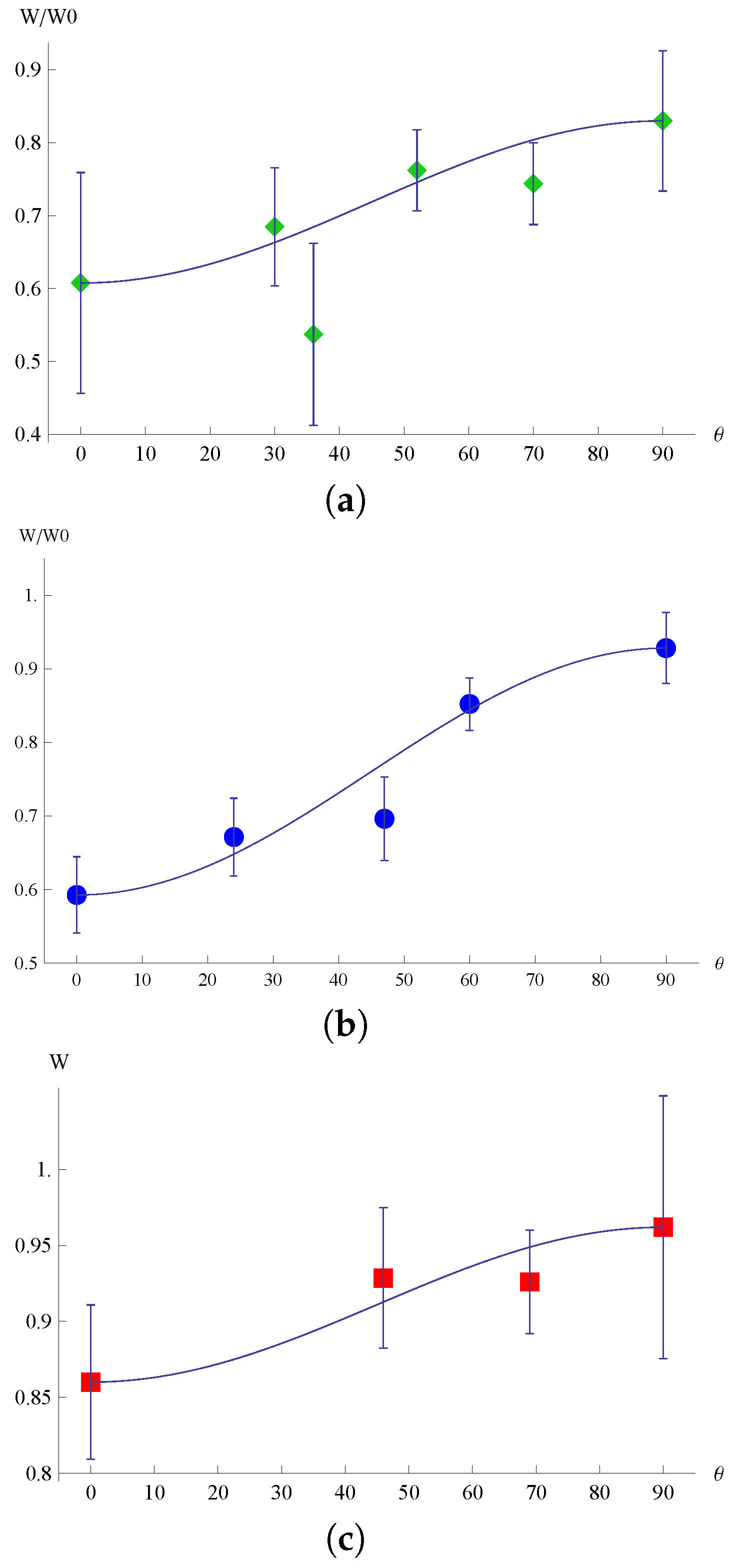
With the quantities and determined for a given configuration, the resistance-force model predict that the terminal vertical speed for fluids under a field at an oblique angle is given by Equation (11). Figure 3 shows a comparison of Equation (11) and measurements made with fields as oblique angles. The theoretical line matches the measurements at the endpoints as these values were used to determine the parameters. Hence, only the intermediate angles compare the model and experiment. Quantitative comparison between the measurements at intermediate angles and the model is limited by the experimental uncertainty of the results, embodied in the standard deviation from the mean value of the terminal-speed measurement, over repeated ball-drop trials in a fixed configuration (magnet and applied-field angle).
4. Discussion
Equation (11), derived from a simplified model of the complex fluid dynamics involved in the flow of the ferrofluid through the matrix of thread-like aggregates, provides a means to quantify the experimental measurements of an anisotropic effect. We adopt this point of view in considering the results, rather than looking to the experiments described in the current work to provide a strong validation the model. In particular, the EFH-1 ferrofluid preparation had an anisotropic resistance comparable to the isotropic resistance due to viscous forces when the applied field was sufficiently strong. Under a weaker applied field, the anisotropy was much less pronounced. Similarly, the selective removal of the larger magnetic nanoparticles (more likely to form aggregates) led to a drastic reduction in anisotropy, as well as a less pronounced magnetoviscous effect.
5. Conclusions
We designed falling ball experiments to examine anisotropic magneto-viscous drag in ferrofluids when uniform fields are applied. Visualization via high intensity X-rays allowed simultaneous tracking of flow and thin elongated structures (threads) formed from the agglomeration of magnetic nano-particles along the field lines. We were unable to precisely quantify the number density or spatial distribution of the threads, but visualization gave rough information about thread diameter and density, including validation of diminished threading due to purification (removal of larger magnetic nano-particles).
A phenomenological model for the thread drag was built that is able to predict the dependence of the terminal velocity on the angle of the applied field (and thus the threads). The model treated the Stokes flow of the falling ball as uniform and neglected the wall effect of the cylindrical container in which the experiments took place. A numerical calculation of total integrated thread array drag for a sphere falling in a finite cylinder has been performed elsewhere [50] and shows only small deviations from the result presented here.
The approach used here is unique in that it used a powerful visualization method to diagnose rheological effects while simultaneously imaging the flow and small scale structures in the fluid. Here, we applied this method to falling spheres in ferrofluid, but it can be generalized to other flows and other complex, difficult to visualize fluids and suspensions.
Acknowledgments
Use of the Advanced Photon Source at Argonne National Laboratory was supported by the U.S. Department of Energy, Office of Basic Energy Sciences. A. David Trubatch and Philip Yecko acknowledge the support of NSF awards DMS-1620158 and DMS-1016383 in this work, while GK12-0638708 supported Alexander Cali.
Author Contributions
A. David Trubatch, Philip Yecko conceived and designed the experiments; Alexander Cali, A. David Trubatch and Philip Yecko performed the experiments, analyzed the data and produced the model; Wah-Keat Lee contributed reagents/materials/analysis tools; A. David Trubatch wrote the article.
Conflicts of Interest
The authors declare no conflict of interest. The sponsors had no role in the design of the study; in the collection, analyses, or interpretation of data; in the writing of the manuscript, nor in the decision to publish the results.
References
- Rinaldi, C.; Chaves, A.; Elborai, S.; He, X.; Zahn, M. Magnetic fluid rheology and flows. Curr. Opin. Colloid Interface Sci. 2005, 10, 141–157. [Google Scholar] [CrossRef]
- Torres-Diaz, I.; Rinaldi, C. Recent progress in ferrofluids research: Novel applications of magnetically controllable and tunable fluids. Soft Matter 2014, 10, 8584–8602. [Google Scholar] [CrossRef] [PubMed]
- Odenbach, S. (Ed.) Ferrofluids: Magnetically Controllable Fluids and Their Applications; Lecture Notes in Physics; Springer: Berlin/Heidelberg, Germany, 2002; Volume 594. [Google Scholar]
- Raj, K.; Hirota, Y.; Black, T. Current and emerging applications of ferrofluids. Magnetohydrodynamics 2013, 49, 568–581. [Google Scholar]
- Trahms, L. Biomedical Applications of Magnetic Nanoparticles. In Colloidal Magnetic Fluids: Basics, Development and Application of Ferrofluids; Lecture Notes in Physics; Odenbach, S., Ed.; Springer: Berlin/Heidelberg, Germany, 2009; Volume 763, pp. 327–358. [Google Scholar]
- Nowak, J.; Wolf, D.; Odenbach, S. A rheological and microscopical characterization of biocompatible ferrofluids. J. Magn. Magn. Mater. 2014, 354, 98–104. [Google Scholar] [CrossRef]
- Jeyadevan, B.; Torigoe, T.; Nakatsuka, K.; Nakatani, I.; Fujita, T.; Oka, H. X-ray image analysis and ultramicroscope study of magnetic fluids used as working liquid in heat transfer experiments. J. Appl. Phys. 1999, 85, 5968–5970. [Google Scholar] [CrossRef]
- Nakatsuka, K.; Jeyadevan, B.; Akagami, Y.; Torigoe, T.; Asari, S. Visual observation of the effect of magnetic field on moving air and vapor bubbles in a magnetic fluid. J. Magn. Magn. Mater. 1999, 201, 256–259. [Google Scholar] [CrossRef]
- Lee, W.; Scardovelli, R.; Trubatch, A.; Yecko, P. Numerical, experimental, and theoretical investigation of bubble aggregation and deformation in magnetic fluids. Phys. Rev. E 2010, 81, 016302. [Google Scholar] [CrossRef] [PubMed]
- Yecko, P.; Lee, W.K.; Trubatch, A.D.; Vieira, M. Drag enhancement due to macro-chains in uniformly magnetized ferrofluids. J. Magn. Magn. Mater. 2011, 323, 1288–1292. [Google Scholar] [CrossRef]
- Hayes, C.F. Observation of association in a ferromagnetic colloid. J. Colloid Interface Sci. 1975, 52, 239–243. [Google Scholar] [CrossRef]
- Horng, H.E.; Hong, C.Y.; Yang, S.Y.; Yang, H.C. Novel properties and applications in magnetic fluids. J. Phys. Chem. Sol. 2001, 62, 1749–1764. [Google Scholar] [CrossRef]
- Jones, G.A. Aggregation of water-based magnetic liquids observed with the polarizing microscope. J. Phys. D-Appl. Phys. 1985, 18, 1281–1290. [Google Scholar] [CrossRef]
- Taketomi, S.; Takahashi, H.; Inaba, N.; Miyajima, H. Experimental and theoretical investigations on agglomeration of magnetic colloidal particles in magnetic fluids. J. Phys. Soc. Jpn. 1991, 60, 1689–1707. [Google Scholar] [CrossRef]
- Isimoto, J.; Okubo, M.; Higashitani, S.K.M. Bubble behavior in magnetic fluid under a nonuniform magnetic field. JSME Int. J. B Fluids Therm. Eng. 1995, 38, 382–387. [Google Scholar] [CrossRef]
- Bashtovoi, V.; Kovalev, M.; Reks, A. Instabilities of bubbles and droplets flows in magnetic fluids. J. Magn. Magn. Mater. 2005, 289, 350–352. [Google Scholar] [CrossRef]
- Drenckhan, W.; Elias, F.; Hutzler, S.; Weaire, D.; Janiaud, E.; Bacri, J.C. Bubble size control and measurement in the generation of ferrofluid foams. J. Appl. Phys. 2003, 93, 10078–10083. [Google Scholar] [CrossRef]
- Wang, Z.; Holm, C.; Muller, H.W. Boundary condition effects in the simulation study of equilibrium properties of magnetic dipolar fluids. J. Chem. Phys. 2003, 119, 379–387. [Google Scholar] [CrossRef]
- Wiedenmann, A.; Heinemann, A. Field-induced ordering phenomena in ferrofluids observed by small-angle neutron scattering. J. Magn. Magn. Mater. 2005, 289, 58–61. [Google Scholar] [CrossRef]
- Krueger, D. Review of agglomeration in ferrofluids. IEEE Trans. Magn. 1980, 16, 251–253. [Google Scholar] [CrossRef]
- Butter, K.; Bomans, P.; Frederik, P.; Vroege, G.; Philipse, A. Direct observation of dipolar chains in iron ferrofluids by cryogenic electron microscopy. Nat. Mater. 2003, 2, 88–91. [Google Scholar] [CrossRef] [PubMed]
- Bacri, J.C.; Salin, D. Optical scattering on ferrofluid agglomerates. J. Phys. Lett. 1982, 34, 771–777. [Google Scholar] [CrossRef]
- Klokkenburg, M.; Erné, B.H.; Meeldijk, J.D.; Wiedenmann, A.; Petukhov, A.V.; Dullens, R.P.A.; Philipse, A.P. In situ imaging of field-induced hexagonal columns in magnetite ferrofluids. Phys. Rev. Lett. 2006, 97, 185702. [Google Scholar] [CrossRef] [PubMed]
- Andelman, D.; Rosensweig, R.E. The Phenomenology of Modulated Phases: From Magnetic Solids and Fluids to Organic Films and Polymers. In Polymers, Liquids and Colloids in Electric Fields: Interfacial Instabilities, Orientation and Phase Transitions; Tsori, Y., Steiner, U., Eds.; Soft Condensed Matter; World Scientific: Singapore, 2009; Volume 2, pp. 1–56. [Google Scholar]
- Lee, W.K. X-ray microtomography of field-induced macro-structures in a ferrofluid. J. Magn. Magn. Mater. 2010, 322, 2525–2528. [Google Scholar] [CrossRef]
- Sano, K.; Doi, M. Theory of agglomeration of ferromagnetic particles in magnetic fluids. J. Phys. Soc. Jpn. 1983, 52, 2810–2815. [Google Scholar] [CrossRef]
- Zubarev, A.Y.; Iskakova, L.Y. To the theory of rheological properties of ferrofluids: Influence of drop-like aggregates. Phys. A Stat. Mech. Appl. 2004, 343, 65–80. [Google Scholar] [CrossRef]
- Odenbach, S.; Raj, K. The influence of large particles and agglomerates on the magnetoviscous effect in ferrofluids. Magnetohydrodynamics 2000, 36, 312–319. [Google Scholar] [CrossRef]
- Thurm, S.; Odenbach, S. Particle size distribution as key parameter for the flow behavior of ferrofluids. Phys. Fluids 2003, 15, 1658–1664. [Google Scholar] [CrossRef]
- Lee, W.K.; Ilavsky, J. Particle size distribution in ferrofluid macro-clusters. J. Magn. Magn. Mater. 2013, 330, 31–36. [Google Scholar] [CrossRef]
- Santiago-Quinones, D.I.; Raj, K.; Rinaldi, C. A comparison of the magnetorheology of two ferrofluids with different magnetic field-dependent chaining behavior. Rheol. Acta 2013, 52, 719–726. [Google Scholar] [CrossRef]
- Chantrell, R.; Sidhu, J.; Bissell, P.; Bates, P. Dilution induced instability in ferrofluids. J. Appl. Phys. 1982, 53, 8341–8343. [Google Scholar] [CrossRef]
- Gerth-Noritzsch, M.; Borin, D.Y.; Odenbach, S. Anisotropy of the magnetoviscous effect in ferrofluids containing nanoparticles exhibiting magnetic dipole interaction. J. Phys. Condens. Matter 2011, 23, 346002. [Google Scholar] [CrossRef] [PubMed]
- Mertelj, A.; Resetic, A.; Gyergyek, S.; Makovec, D.; Copic, M. Anisotropic microrheological properties of chain-forming magnetic fluids. Soft Matter 2011, 7, 125–131. [Google Scholar] [CrossRef]
- Ghosh, S.; Puri, I.K. Soft polymer magnetic nanocomposites: Microstructure patterning by magnetophoretic transport and self-assembly. Soft Matter 2013, 9, 2024–2029. [Google Scholar] [CrossRef] [PubMed]
- Rosensweig, R.E.; Keiser, R.; Miskolczy, G. Viscosity of magnetic fluid in a magnetic field. J. Colloid Interface Sci. 1969, 29, 680–686. [Google Scholar] [CrossRef]
- Shliomis, M.I. Effective viscosity of magnetic suspensions. Sov. Phys. JETP 1972, 34, 1291–1294. [Google Scholar]
- Rosensweig, R.E. Ferrohydrodynamics; Cambridge University Press (Dover): New York, NY, USA, 1984 (1997).
- De Gennes, P.G.; Pincus, P.A. Pair correlations in a ferromagnetic colloid. Z. Phys. B Condens. Matter 1970, 11, 189–198. [Google Scholar] [CrossRef]
- Rosensweig, R. Towards ferrofluids with enhanced magnetization. J. Magn. Magn. Mater. 2011, 323, 1191–1197. [Google Scholar] [CrossRef]
- McTague, J.P. Magnetoviscosity of magnetic colloids. J. Chem. Phys. 1969, 51, 133–136. [Google Scholar] [CrossRef]
- Kamiyama, S.; Satoh, A. Rheological properties of magnetic fluids with the formation of clusters: Analysis of simple shear flow in a strong magnetic field. J. Colloid Interface Sci. 1989, 127, 173–188. [Google Scholar] [CrossRef]
- Felicia, L.; Vinod, S.; Philip, J. Recent advances in magnetorheology of ferrofluids (magnetic nanofluids)—A critical review. J. Nanofluids 2016, 5, 1–22. [Google Scholar] [CrossRef]
- Cunha, F.R.; Rosa, A.P.; Dias, N.J. Rheology of a very dilute magnetic suspension with micro-structures of nanoparticles. J. Magn. Magn. Mater. 2016, 397, 266–274. [Google Scholar] [CrossRef]
- Linke, J.; Odenbach, S. Anisotropy of the magnetoviscous effect in a ferrofluid with weakly interacting magnetic nanoparticles. J. Phys. Condens. Matter 2015, 27, 176001. [Google Scholar] [CrossRef] [PubMed]
- Dohmen, E.; Borin, D.; Zubarev, A. Magnetic field angle dependent hysteresis of a magnetorheological suspension. J. Magn. Magn. Mater. 2017, 443, 275–280. [Google Scholar] [CrossRef]
- Batchelor, G.K. Slender-body theory for particles of arbitrary cross-section in Stokes flow. J. Fluid Mech. 1970, 44, 419–440. [Google Scholar] [CrossRef]
- Lauga, E.; Powers, T.R. The hydrodynamics of swimming microorganisms. Rep. Prog. Phys. 2009, 72, 096601. [Google Scholar] [CrossRef]
- Franklin, T.A. Ferrofluid Flow Phenomena. Ph.D. Thesis, Massachusetts Institute of Technology, Cambridge, MA, USA, June 2003. [Google Scholar]
- Cali, A. Magnetoviscous Effects of Magnetized Particle Threads in Magnetized Ferrofluids. Master’s Thesis, Montclair State University, Montclair, NJ, USA, 2014. [Google Scholar]
Figure 1.
Schematic diagram of the Experiment.
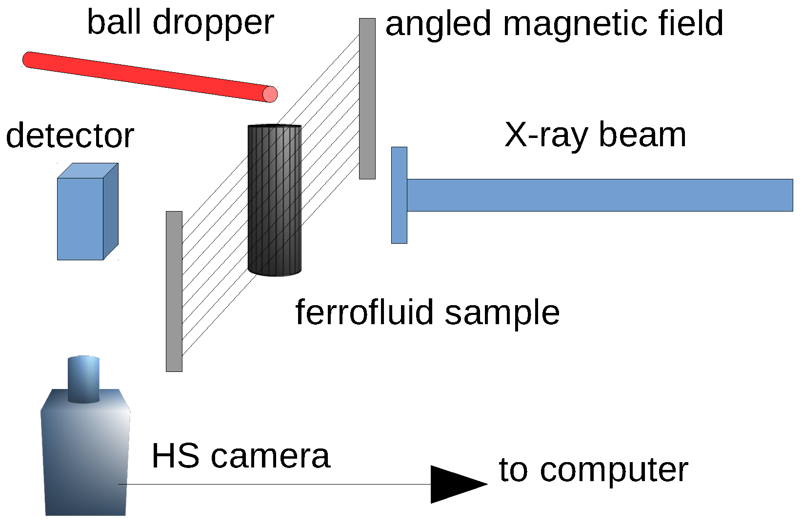
Figure 2.
X-ray, phase-contrast image of magnetized bulk ferrofluid, showing (i) thread-like aggregates aligned with direction of applied uniform magnetic field; and (ii) falling spherical glass ball.
Figure 2.
X-ray, phase-contrast image of magnetized bulk ferrofluid, showing (i) thread-like aggregates aligned with direction of applied uniform magnetic field; and (ii) falling spherical glass ball.

Figure 3.
Normalized speed vs. angle of the applied field, experimental measurements and model interpolation as in Equation (11): (a) EFH-1 fluid and magnet B; (b) EFH-1 fluid and magnet B; (b) EFH-1 fluid and magnet C; (c) P2XD fluid and magnet C; the value for each configuration is the mean over several repeated “ball-drop” trials in that configuration; the error bars are the standard-deviation from the mean value for the repeated trials in a given configuration.

Table 1.
Measured magnetoviscosity factor, , and anisotropy factor for the two applied field strengths (C magnet: 980 G, B magnet: 490 G) and types of ferrofluid (EFH-1, P2XD purified, see text) used in the experiments.
Table 1.
Measured magnetoviscosity factor, , and anisotropy factor for the two applied field strengths (C magnet: 980 G, B magnet: 490 G) and types of ferrofluid (EFH-1, P2XD purified, see text) used in the experiments.
| Configuration | ||
|---|---|---|
| EFH-1 with B magnet | 0.76 | 0.58 |
| EFH-1 with C magnet | 0 .47 | 1.31 |
| P2XD with C magnet | 0.92 | 0.13 |
© 2017 by the authors. Licensee MDPI, Basel, Switzerland. This article is an open access article distributed under the terms and conditions of the Creative Commons Attribution (CC BY) license (http://creativecommons.org/licenses/by/4.0/).
Share and Cite
MDPI and ACS Style
Cali, A.; Lee, W.-K.; Trubatch, A.D.; Yecko, P. Flow Anisotropy due to Thread-Like Nanoparticle Agglomerations in Dilute Ferrofluids. Fluids 2017, 2, 67. https://doi.org/10.3390/fluids2040067
AMA Style
Cali A, Lee W-K, Trubatch AD, Yecko P. Flow Anisotropy due to Thread-Like Nanoparticle Agglomerations in Dilute Ferrofluids. Fluids. 2017; 2(4):67. https://doi.org/10.3390/fluids2040067
Chicago/Turabian StyleCali, Alexander, Wah-Keat Lee, A. David Trubatch, and Philip Yecko. 2017. "Flow Anisotropy due to Thread-Like Nanoparticle Agglomerations in Dilute Ferrofluids" Fluids 2, no. 4: 67. https://doi.org/10.3390/fluids2040067