Article

Effects of Lewis Number on the Evolution of Curvature in Spherically Expanding Turbulent Premixed Flames

1
School of Engineering, Newcastle University, Newcastle-Upon-Tyne NE1 7RU, UK
2
Department of Aerospace Engineering, Bundeswehr University Munich, LRT1, Werner-Heisenberg-Weg 39, 85577 Neubiberg, Germany
*
Author to whom correspondence should be addressed.
Fluids 2019, 4(1), 12; https://doi.org/10.3390/fluids4010012
Submission received: 30 November 2018 / Revised: 7 January 2019 / Accepted: 11 January 2019 / Published: 16 January 2019
(This article belongs to the Special Issue Numerical Simulations of Turbulent Combustion)

Abstract

:
The effects of Lewis number on the physical mechanisms pertinent to the curvature evolution have been investigated using three-dimensional Direct Numerical Simulation (DNS) of spherically expanding turbulent premixed flames with characteristic Lewis number of L e = 0.8 , 1.0 and 1.2. It has been found that the overall burning rate and the extent of flame wrinkling increase with decreasing Lewis number L e , and this tendency is particularly prevalent for the sub-unity Lewis number (e.g., L e = 0.8 ) case due to the occurrence of the thermo-diffusive instability. Accordingly, the L e = 0.8 case has been found to exhibit higher probability of finding saddle topologies with large magnitude negative curvatures in comparison to the corresponding L e = 1.0 and 1.2 cases. It has been found that the terms in the curvature transport equation due to normal strain rate gradients and curl of vorticity arising from both fluid flow and flame normal propagation play pivotal roles in the curvature evolution in all cases considered here. The net contribution of the source/sink terms of the curvature transport equation tends to increase the concavity and convexity of the flame surface in the negatively and positively curved locations, respectively for the L e = 0.8 case. This along with the occurrence of high and low temperature (and burning rate) values at the positively and negatively curved zones, respectively acts to augment positive and negative curved wrinkles induced by turbulence in the L e = 0.8 case, which is indicative of thermo-diffusive instability. By contrast, flame propagation effects tend to weakly promote the concavity of the negatively curved cusps, and act to decrease the convexity of the highly positively curved bulges in the L e = 1.0 and 1.2 cases, which are eventually smoothed out due to high and low values of displacement speed S d at negatively and positively curved locations, respectively. Thus, flame propagation tends to smoothen the flame surface in the L e = 1.0 and 1.2 cases.

1. Introduction

Spherically expanding turbulent premixed flames are of fundamental importance in Spark Ignition (SI) engines and for understanding accidental explosions. Hence, they are often used as a canonical configuration for laboratory-scale experiments [1,2,3,4,5,6,7,8,9] and numerical investigations [10,11,12,13,14,15,16,17,18,19,20,21,22,23,24,25,26,27,28,29,30,31]. The role of mean flame curvature [20,21,22,26] on Flame Surface Density (FSD) [20,25] and Scalar Dissipation Rate (SDR) [25,27], which are central to determine the fuel burning rate, has been demonstrated in several previous DNS studies on ignition kernels [11,22] and spherically expanding flames [15,17,18,19,20,21,22,23,24,25,26,27]. Moreover, LES of spherical flames using the flame wrinkling factor [14,16], FSD [27,29] and combined FSD-probability density function (PDF) [28] sub-grid closures, and Reynolds Averaged Navier–Stokes (RANS) simulations using various combustion modelling approaches [10,13,30] showed good agreement with experimental measurements. However, several analyses [20,21,22,24,27,30,31] demonstrated that there are significant differences between statistically planar and spherical flames, specifically in terms of flame propagation and fuel burning rate. Although these past studies provided important physical insights on spherical flames, they seldom considered thermo-diffusive effects arising from differential diffusion of heat and mass, characterised by Lewis number L e (i.e., ratio of thermal and mass diffusivities). The presence of thermo-diffusive instabilities augments the burning rate as demonstrated in experiments [4,5] and thus spherical flames in lean hydrogen–air mixture grow quicker compared to those in hydrocarbon–air mixture under statistically similar turbulent flow conditions. The necessity to include these effects was demonstrated by computing stoichiometric and fuel-lean hydrogen–air and methane–air spherical flames [30,31].
The flame wrinkling is often characterised in terms of flame front curvature distribution, which plays a key role in determining the local flame propagation behaviour. This is reflected in the correlation between displacement speed S d and curvature κ m [21,22,24,32,33,34,35,36,37,38,39,40,41]. Moreover, in non-unity Lewis number flames the consumption speed S c also demonstrates correlation with local flame curvature κ m [42]. Furthermore, tangential strain rate and curvature have been found to be negatively correlated for small turbulence intensities and the strengths of the correlations of tangential strain rate and flame speed with curvature weaken with increasing turbulence intensity. The flame curvature κ m is also known to affect the curvature and propagation terms in the Surface Density Function (SDF = | c | with c being the reaction progress variable) transport equation [43,44,45,46,47,48,49,50], which in turn influence the evolutions of FSD and SDR [27,29,30,31,50]. It has been demonstrated in several previous analyses [27,39,44,47] that the curvature dependences of displacement speed, temperature and SDF are influenced by the characteristic Lewis number L e , and thus it is expected that the curvature evolution is also likely to be affected by L e .
Pope [51] derived a transport equation for a parameterised surface and recently, Dopazo et al. [52] derived a transport equation of flame front curvature κ m and analysed the statistical behaviours of the different terms of this transport equation for passive scalar mixing without the effects of heat release. This analysis has been extended by Cifuentes et al. [53] to analyse the statistical behaviours of the terms in the curvature transport equation in a bluff-body stabilised turbulent premixed flame burner configuration using a flame-resolved high-fidelity simulation. However, the effects of characteristic Lewis number on the flame curvature evolution in a configuration with a non-zero mean curvature, as in the case of spherically expanding turbulent premixed flames, are yet to be analysed in detail. For example, the reasons for the differences in flame topology in terms of curvature distribution in response to the variation of L e , and the predominance of positively curved bulges and the presence of intermediate sharply negatively curved cusps between positively curved bulges for the L e < 1 flames have not been sufficiently explained in the existing literature. This distribution has strong implications on the augmentation of flame wrinkling and overall burning rate with decreasing Lewis number [39,42,44,54,55,56,57,58]. Thus, it is important to gain a better understanding of the curvature evolution in the presence of thermo-diffusive instabilities and their interrelation with flame shape and propagation in order to be able to derive high fidelity models, which can predict the non-unity Lewis number effects on premixed turbulent combustion. The flame curvature transport equation in Cartesian coordinates is a relatively new concept and the effects of thermo-diffusive instabilities on curvature transport are yet to be understood in detail. In order to address the aforementioned deficits in the existing literature, the statistical behaviours of the curvature transport have been analysed in this paper for statistically spherical flames with characteristic Lewis numbers L e = 0.8 , 1.0 and 1.2. In this respect, the main objectives of this paper are:
  • To demonstrate the effects of Lewis number on the terms of the transport equation of flame curvature κ m in spherically expanding turbulent premixed flames.
  • To identify the mechanisms, which lead to the effects of thermo-diffusive instability (i.e., augmentation of burning rate and flame wrinkling and a positive correlation between local burning rate and flame curvature) in the flames with L e < 1 .
The mathematical and numerical background pertaining to this analysis are presented in the next two sections of this paper. Following that, the results will be presented and subsequently discussed. The main findings will be summarised and conclusions are drawn in the final section of this paper.

2. Mathematical Background

In the current analysis, the chemical mechanism has been simplified by a single-step irreversible reaction so that the effects of characteristic Lewis number L e can be investigated in isolation, as done in several previous analyses [39,40,41,42,44,54,55,56,57,58]. The present analysis considers three characteristic Lewis numbers L e = 0.8 ,   1.0 and 1.2 following previous analyses [39,40,41,42,44,54,55,56,57,58]. Furthermore, the current analysis only focuses on Lewis number effects (i.e., differential diffusion of heat and mass) and not the differential diffusion between species.
In the case of non-unity Lewis number flames, the scalar field can be characterised by the reaction progress variable c and non-dimensional temperature θ , which are defined as:
c = Y R 0 Y R Y R 0 Y R
θ = ( T T 0 ) ( T a d T 0 )
where Y R is the mass fraction of a suitable reactant which is used for defining the reaction progress variable. The subscripts 0 and are used to refer to values in the unburned gas and fully burned products, respectively. In Equation (2), T , T 0 and T a d denote the dimensional temperature, unburned gas temperature and adiabatic flame temperature, respectively.
The transport equation of the reaction progress variable c ( x , t ) is given by:
c t + u j   c x j = 1 ρ x j ( ρ D c c x j ) + w ˙ c = 1 ρ x N ( ρ D c c x N ) + D c c x N n i , i + w ˙ c
where u j is the jth component of the flow velocity, ρ is the fluid density, D c is the diffusivity of c and w ˙ c is chemical reaction rate. The reaction rate w ˙ c variation with c for the present thermo-chemistry is shown in Figure 1 of ref. [59] and thus will not be repeated in this paper. The flame normal vector, n , of a c iso-surface is defined as: n i = ( c / x i ) / | c | = c , i / | c | = c , i / ( c / x N ) , where x N is the coordinate in the normal direction to the iso-surface. The quantity, n i , i / 2 = 0.5 n i / x i = κ m is the mean value of two principal curvatures of the iso-surface and will henceforth be referred to as the flame curvature in this paper. According to the convention used here, the flame normal points towards the reactants and the flame surface has a positive (negative) curvature where it is convex (concave) to the reactants. The transport equation of c ( x , t ) can alternatively be presented in the kinematic form as [21,22,24,32,33,34,35,36,37,38,39,40,41]:
c t + u j c x j = S d | c |
where S d is the displacement speed, which is expressed as [21,22,24,32,33,34,35,36,37,38,39,40,41]:
S d ( x , t ) =   1 ρ | c | x N ( ρ D c c x N ) 2 D c κ m + w ˙ c | c |
Differentiating Equation (3) with respect to x i yields [52,53]:
1 | c | ( | c | t + v j c | c | x j ) = n i v j , i c n j
n i t + v j c n i x j = ( δ i j n i n j ) S j k c n k + W i j c n j ;
where v j c = u j + S d n j is the jth component of local propagation velocity of a given c isosurface. The quantity n i v j , i c n j = n i S i j c n j = a N c = a N + S d / x N is often referred to as the total or effective normal strain rate [46,48,49,53,56,57], whereas a N = n i S i j n j is the fluid-dynamic normal strain rate and S d / x N is an added normal strain rate induced by flame propagation [46,48,49,53,60,61]. The gradient of the flame propagation velocity v j c takes the following form [52,53]:
v j , i c = v j c x i = 1 2 ( v j c x i + v i c x j ) + 1 2 ( v j c x i v i c x j ) =   1 2 ( u j x i + u i x j ) + 1 2 ( u j x i u i x j ) + 1 2 ( S d x i n j + S d x j n i ) + 1 2 ( S d x i n j S d x j n i ) + S d 1 2 ( n j x i + n i x j ) + S d 1 2 ( n j x i n i x j ) = S i j c W i j c
Table 1 presents the nomenclature associated with Equation (8), where the total strain rate and rotation rate tensors are expressed as S i j c = S i j + S i j a and W i j c = W i j + W i j a respectively [52,53]. The strain rate S i j and rotation rate W i j tensors originate due to the fluid motion, and the additional strain rate S i j a and rotation W i j a rate tensors originate due to the gradients of spatially dependent S d .
Taking the derivative with respect to x i on both sides of Equation (7) yields a transport equation of κ m = 0.5 ( κ 1 + κ 2 ) = 0.5 n i , i (with κ 1 and κ 2 being the two principal curvatures) [52,53]:
κ m t + v j c   κ m x j = a N ( n i , i ) 2 T 1 + 1 2 a N x N T 2 S i j n j , i T 3 1 2 S i j x i n j T 4 + 1 2 W i j x i n j T 5 f l o w   t e r m s + 1 2 S d x N n i , i T 6 + 1 2 2 S d x N 2 T 7 S i j a n j , i T 8 1 2 S i j a x i n j T 9 + 1 2 W i j a x i n j T 10 a d d e d   t e r m s
The terms T 1 5 arise due to fluid motion, whereas T 6 10 originate due to flame propagation. The positive (negative) contributions of these terms tend to increase the convexity (concavity) of iso-surfaces. The physical significances of the terms on the right side of Equation (9) are summarised in Table 2.
It can be appreciated from Equation (9) that curvature transport depends mainly on the statistics of fluid velocity/vorticity, scalar gradient and displacement speed. It has been demonstrated in the past that displacement speed statistics from simple chemistry [38,39,40,41,45] and detailed chemistry [32,33,34,35,36,37] DNS are qualitatively similar. The same is true for the statistics of the reactive scalar gradient obtained from simple chemistry [43,44,45,62] and detailed chemistry [47,62] DNS studies. Moreover, the vorticity and sub-grid flux statistics obtained from simple chemistry [59,63,64] DNS are found to be qualitatively consistent with those obtained from detailed chemistry [65,66] DNS. Furthermore, several models developed based on simple chemistry data [64,67,68] have been found to perform equally well in the context of detailed chemistry and transport [66,69,70].

3. Numerical Implementation

In the present analysis, DNS simulations of spherically expanding turbulent premixed flames with L e = 0.8 , 1.0 and 1.2 have been carried out using a well-known compressible code SENGA [71] where the conservation equations of mass, momentum, energy and reaction progress variable have been solved in non-dimensional form. The L e = 0.8 case is representative of hydrogen-blended methane-air mixtures (e.g., 10% by volume hydrogen blended methane-air flames with overall equivalence ratio of 0.6) and the Lewis number 1.2 case is representative of a hydrocarbon-air mixture involving a hydrocarbon fuel which is heavier than methane (e.g., ethylene-air mixture with equivalence ratio of 0.7) [72,73]. The unity Lewis number flames are analogous to the stoichiometric methane-air flame [72,73]. The spatial discretisation for internal grid points has been carried out using a 10th order central difference scheme and the order of differentiation decreases gradually to a one-sided 2nd order scheme at the non-periodic boundaries [71]. The time-advancement has been carried out using a 3rd order explicit Runge–Kutta scheme [74]. The computational domain is taken to be a cube of 58.10 δ t h × 58.10 δ t h × 58.10 δ t h (where δ t h = ( T a d T 0 ) / max | T | L is the thermal flame thickness and the subscript ‘L’ is used to refer to conditions in the unstrained laminar premixed flame), which is discretised by a uniform Cartesian grid of 650 × 650 × 650 . In all the cases considered here, the boundaries of the computational domain are taken to be partially non-reflecting and are specified using the Navier–Stokes Characteristic Boundary conditions (NSCBC) technique [75]. The reacting scalar fields obtained from a steady state unstrained laminar flame have been utilised to create a burned gas sphere with its centre initially at the centre of the domain. This reacting scalar field is allowed to evolve in a quiescent environment at least for one chemical time scale (i.e., t = δ t h / S L ). For all simulations, standard values are taken for Prandtl number P r and Zel’dovich number β = T a c ( T a d T 0 ) / T a d 2 (i.e., P r = 0.7 and β = 6.0 with T a c being the activation temperature) and the heat release parameter τ = ( T a d T 0 ) / T 0 is taken to be 4.5 for all cases considered here. The spherical laminar flame kernels for different Lewis numbers with a normalised radius of r S L / α T 0 = 10.6 (where α T 0 is the thermal diffusivity of the unburned gas) based on the region corresponding to c 0.85 have been considered as the initial condition for turbulent simulations. A standard pseudo-spectral method [76] has been adopted to initialise homogeneous isotropic turbulent velocity fluctuations following the model spectrum by Pope [77]. For all cases the initial values of the normalised root-mean-square velocity fluctuation and longitudinal integral length scale are given by: u / S L = 7.5 and l / δ t h = 4.58 , respectively. These values of u / S L and l / δ t h are representative of the thin reaction zones regime of combustion according to the regime diagram by Peters [78]. All the turbulent simulations have been continued for 2 initial eddy turnover times (i.e., t = l / k where k is the turbulent kinetic energy based on the whole domain), which is equivalent to 1.0 chemical timescale (i.e., t c h e m = δ t h / S L ). By this time, the turbulent kinetic energy was not varying rapidly with time and u decayed by 40% in comparison to its initial value.

4. Results and Discussion

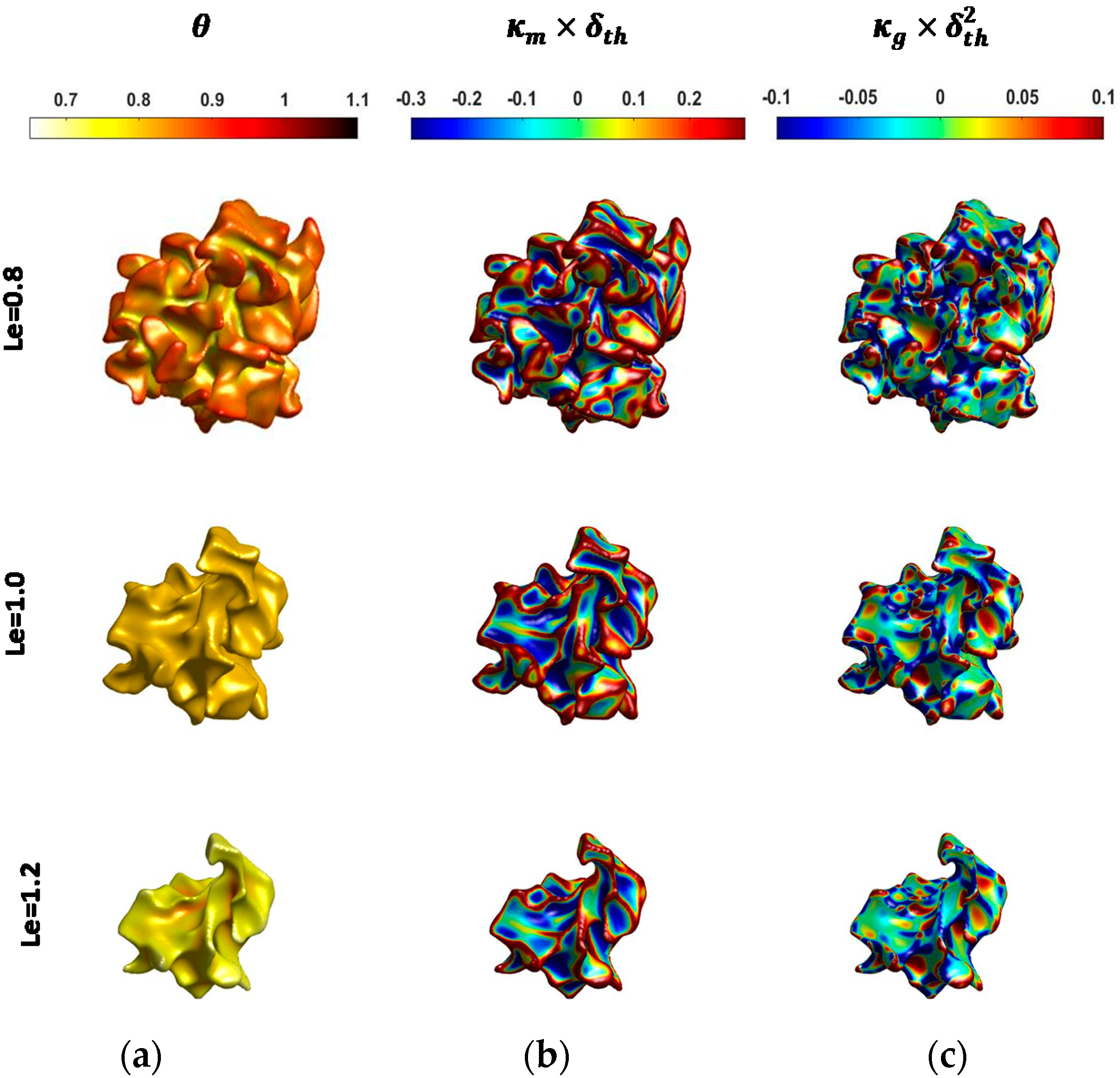
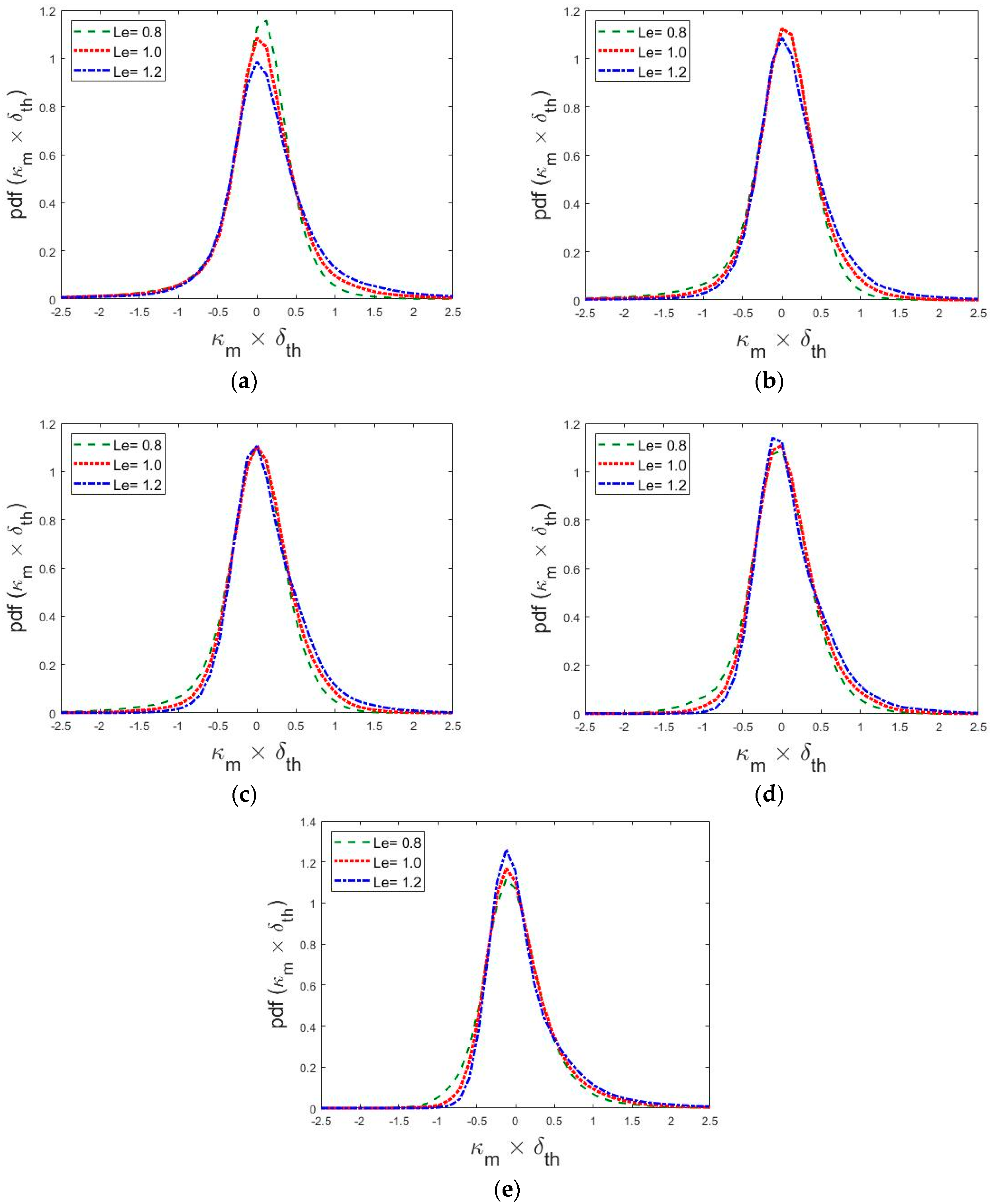
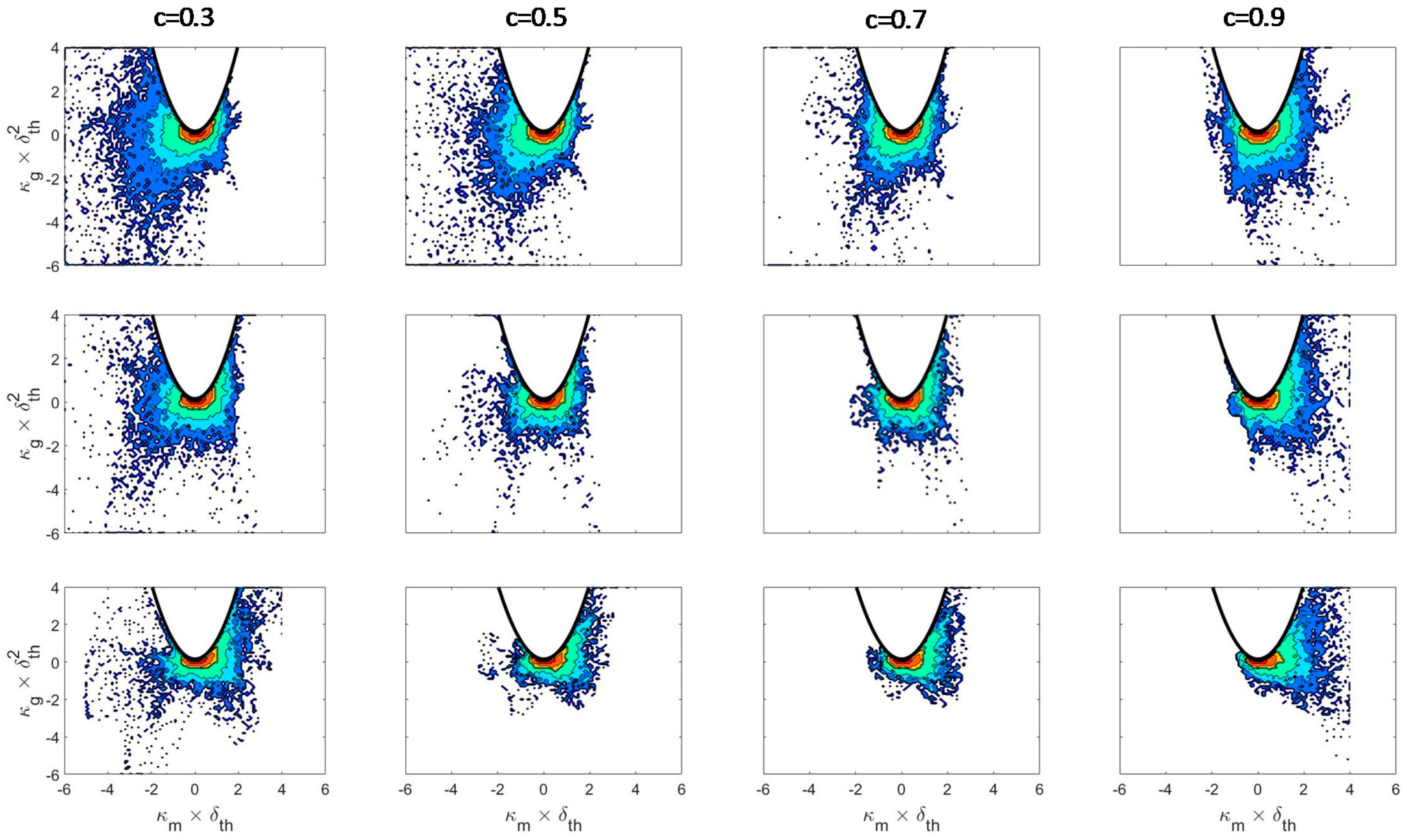
4.1. Curvature Characterisation

The flame topology is often characterised by the mean of principal curvatures (i.e., κ m = 0.5 ( κ 1 + κ 2 ) ) and Gauss curvature κ g = κ 1 κ 2 [79] where κ 1 and κ 2 are the principal curvatures. The c = 0.8 isosurface coloured by local values of non-dimensional temperature θ , normalised mean curvature κ m × δ t h and normalised Gauss curvature κ g × δ t h 2 for the L e = 0.8 , 1.0 and 1.2 flames are shown in Figure 1. It is worth noting that the reaction rate w ˙ c assumes maximum value close to c = 0.8 for the present thermochemistry and this isosurface can be taken to be the flame surface for the purpose of this analysis.
It is evident from Figure 1 that the extent of wrinkling and burned gas volume increase with decreasing L e , and especially the occurrences of saddle point topologies (i.e., κ g < 0 ) and sharply negatively curved cusps (i.e., large magnitudes of negative κ m ) increase with decreasing Lewis number. The augmentation of flame wrinkling with decreasing L e has implications on the extent of burning and flame surface area, which can be substantiated from Table 3 where the normalised volume-integrated burning rate Ω T / Ω L and flame surface area A T / A L are listed. Here, Ω and A are evaluated by volume-integrals Ω = V ρ w ˙ c d V and A = V | c | d V , respectively and the subscripts T and L refer to the values in turbulent flame and initial laminar flame kernels, respectively. The fresh reactants diffuse faster into the reaction zone than the rate at which heat diffuses out in the L e = 0.8 flame. This gives rise to higher burning rate in the L e = 0.8 flame than in the corresponding unity Lewis number case. The diffusion of reactants is slower into the reaction zone than the rate at which heat diffuses out in the L e = 1.2 flame, which in turn reduces the burning rate in the L e = 1.2 case than in the corresponding unity Lewis number case. This is qualitatively consistent with several previous findings [1,39,41,42,44,54,55,56,57,58].
It can be seen from Figure 1 that high temperature zones are associated with positive κ m values in the L e = 0.8 case, whereas the high temperature zones are associated with negatively curved zones (i.e., κ m < 0 ) in the L e = 1.2 case. The non-dimensional temperature θ remains uniform and equal to 0.8 (i.e., θ = c = 0.8 ) on the c = 0.8 isosurface in the unity Lewis number case. The statistically spherical flames have predominantly positive curvatures where the combination of strong focussing of reactants and weak defocussing of heat gives rise to high reaction rate in the positively curved regions in the L e = 0.8 flame. Just the opposite mechanisms lead to low reaction rate at the negatively curved regions in the L e = 0.8 flame. This also gives rise to θ > c at the positively curved locations in the L e = 0.8 flame. As a result of this, the L e = 0.8 case exhibits stable positively curved bulges with large radius of curvature separated by sharply negatively curved cusps. In the L e = 1.2 case, the focussing of heat is faster than the defocussing of reactants at the negatively curved locations, which increases the reaction rate magnitude in these locations and may give rise to local occurrences of θ > c . Thus, the sharply negatively curved pockets burn faster in the L e = 1.2 case and as a result sharp negatively curved cusps with small radius of curvature are unlikely to survive in this case. The unity Lewis number case is thermo-diffusively neutral and thus, for low-Mach number adiabatic conditions, the non-dimensional temperature θ remains equal to the reaction progress variable.
The high temperature values at the positively curved zones significantly increase the fuel consumption rate per unit area in the turbulent L e = 0.8 case in comparison to the corresponding unstrained laminar flame value and this gives rise to a Ω T / Ω L value, which is greater than A T / A L . The consumption rate per unit area in the turbulent L e = 1.0 case remains comparable to the corresponding unstrained laminar flame value and thus Ω T / Ω L and A T / A L remain close to each other. The combination of strong thermal diffusion and weak diffusion of reactants into the reaction zone reduces the consumption rate per unit area in the positively stretched zones in turbulent L e = 1.2 case in comparison to the corresponding unstrained laminar flame value, which results in Ω T / Ω L < A T / A L in this case.
The probability density functions (PDFs) of normalised curvature κ m × δ t h for different c -isosurfaces across the flame front are shown in Figure 2. It is evident from Figure 2 that the width of the curvature PDFs tends to increase with decreasing Lewis number due to increased flame wrinkling with decreasing Lewis number L e . The most probable value of κ m has been found to be close to zero for all flame kernels considered here but the mean value of κ m remains positive due to the statistically spherical configuration. In the L e 1 flames, the PDFs of normalised curvature κ m × δ t h remain almost symmetric around κ m × δ t h = 0 towards the unburned gas side of the flame front (e.g., c = 0.1 ) due to the strong deformation of the flame surface as a result of the interaction between energetic eddies with the preheat zone. However, the PDFs of normalised curvature κ m × δ t h exhibit higher propensity to obtain positive values for the major part of flame front. It can be seen from Figure 2 that the high magnitudes of negative κ m are more frequent for the c = 0.5 ,   0.7 and 0.9 isosurfaces in the L e = 0.8 case than in the corresponding L e = 1.0 and 1.2 cases. This tendency for the L e = 0.8 flame could be a consequence of thermo-diffusive instability associated with L e < 1 , where sharply negative curved cusps with small radii of curvature are found in between positively curved bulges with large or moderate radii of curvature.
The Joint Probability Density Functions (JPDFs) of normalised mean curvature κ m × δ t h and normalised Gauss curvature κ g × δ t h 2 for different c iso-surfaces across the flame are shown in Figure 3. The region corresponding to κ g > κ m 2 on the κ m κ g plane corresponds to complex principal curvature values and thus cannot be realised in practice. The combination of κ m > 0 ( κ m < 0 ) and κ g > 0 corresponds to cup convex (concave) shapes. By contrast, the combination of κ m > 0 ( κ m < 0 ) and κ g < 0 corresponds to saddle convex (concave) shapes. Finally, the combination of κ m > 0 ( κ m < 0 ) and κ g = 0 corresponds to tile convex (concave) flame topologies. For a schematic diagram of these topologies interested readers are referred to Figure 1 of ref. [53]. The spread of κ m × δ t h values on both positive and negative sides for the L e = 0.8 case is greater than that in the corresponding L e = 1.0 and 1.2 cases, which is indicative of larger extent of flame wrinkling in the L e = 0.8 case (see Figure 1 and Table 3). The highest values of joint PDFs are obtained for a positive value of κ m close to κ m 0 , which is consistent with the observations made from Figure 2. Figure 3 demonstrates that the joint PDFs in the L e = 0.8 case show skewness for the negative values of κ m × δ t h on the unburned gas side of the flame, but the joint PDFs eventually become skewed towards the positive values of κ m as the burned gas side is approached. The distribution depicted by the joint PDF also shows a propensity to obtain predominantly positive κ m towards the burned gas side of the flame front for both L e = 1.0 and 1.2 cases but this tendency is more prevalent for the L e = 1.2 case. The high probability of finding negatively curved cusps ( κ m < 0 ) for the L e = 0.8 case is a reflection of the thermo-diffusive instability in this flame. Both cup and saddle topologies appear considerably for convex and concave curvatures throughout the flame front in all cases. However, the cup like topology, whether for concave or convex structure, is more probable than the saddle and tile topologies for all cases considered here. The probability of finding saddle topologies decreases from the unburned to the burned gas side for all flames considered here. Moreover, the probability of finding saddle topologies decreases with increasing L e , which is consistent with the observations made from Figure 1.
The budgets of the various terms in the curvature transport equation conditional on c will be discussed in the next section. Based on this analysis it will be possible to judge the magnitude of the different terms and which terms possibly balance each other. Beside this, another focus of this paper is to establish a relation between the terms of the curvature transport equation and flame instabilities that might occur under certain conditions. It will therefore be instructive to analyse the terms T 1 ,   , T 10 conditional on mean curvature in the next but one section. Only by this additional representation, it will be possible to understand if positive or negative flame curvature elements are damped or possibly amplified in the presence of flame instabilities.

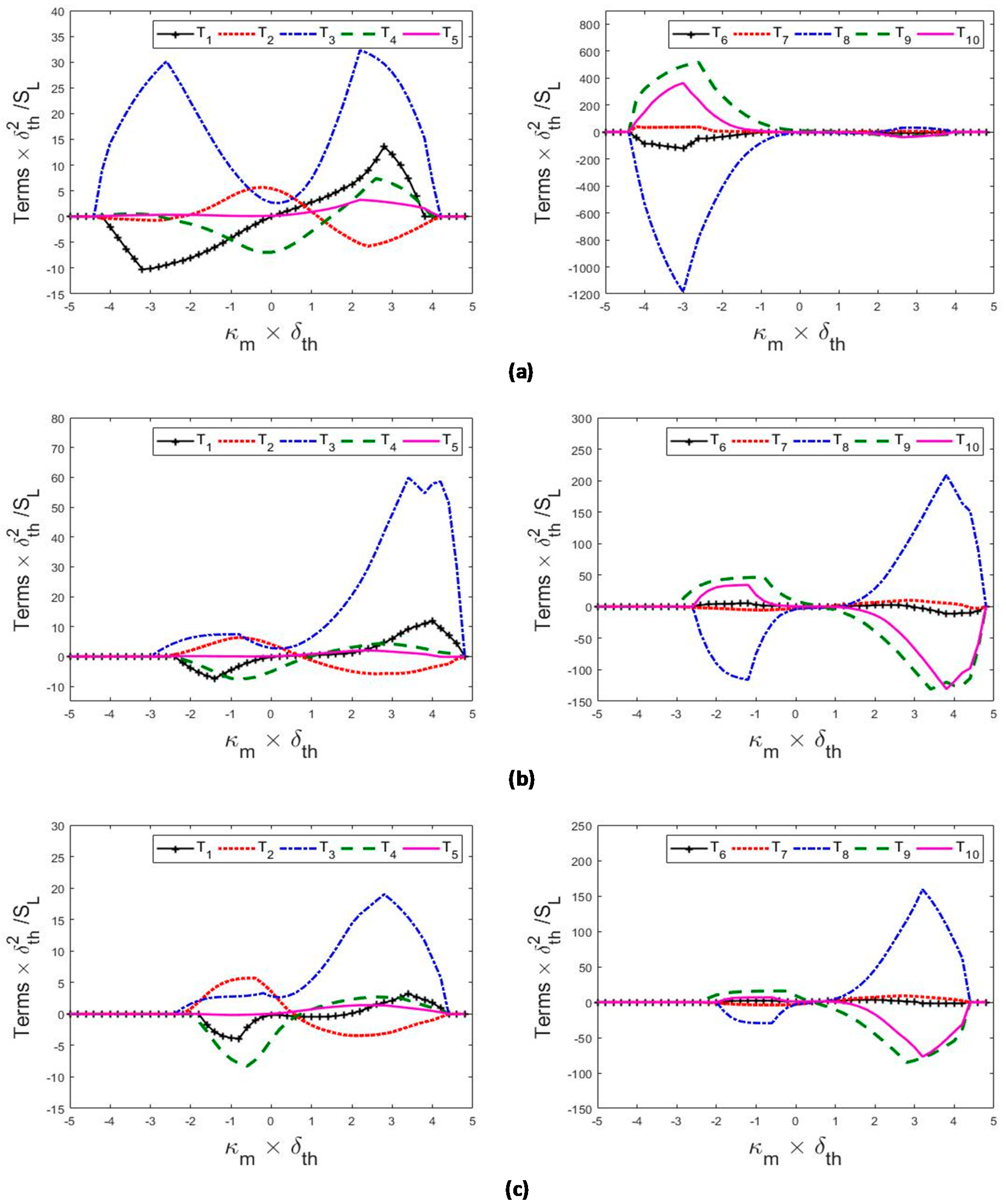
4.2. Mean Profiles of Source/Sink Terms of the Curvature Transport Equation

The profiles of mean values of T i × δ t h 2 / S L conditional on c for L e = 0.8 ,   1.0 and 1.2 cases are shown in Figure 4a–c respectively. The objective of Figure 4 is to provide insights into the mean behaviour of the terms on the right-hand side of the curvature transport equation (i.e., Equation (9)) across the flame. It can be seen from Figure 4 that the term T 1 × ( δ t h 2 / S L ) , originating from the correlation between curvature and normal strain rate, assumes weakly negative values for the major part of the flame front for the for L e = 1.0 and 1.2 cases. In these cases, the mean value of T 1 × ( δ t h 2 / S L ) remains weakly positive towards the burned gas side of the flame front. However, the mean values of T 1 × ( δ t h 2 / S L ) remain positive throughout the flame front for the L e = 0.8 case. Therefore, the term T 1 tends to increase the convexity of iso-surface in the L e = 0.8 case, while the opposite behaviour is obtained in the L e = 1.0 and 1.2 cases. In the L e = 1.0 and 1.2 flames the reaction progress variable gradient c aligns predominantly with the most compressive principal strain rate due to stronger turbulent straining than the strain rate arising from flame normal acceleration induced by chemical heat release. This leads to predominantly negative normal strain rate a N = ( e α cos 2 θ α + e β cos 2 θ β + e γ cos 2 θ γ ) (where e α , e β and e γ are the most extensive, intermediate and the most compressive eigenvalues of the strain rate tensor S i j = 0.5 ( u i / x j + u j / x i ) and θ α , θ β and θ γ are the angles of their eigenvectors with c , respectively) in the L e = 1.0 and 1.2 flames considered here. In these cases, c exhibits some tendency for local preferential collinear alignment with e α only in the heat release zone. However, the alignment of c with the most extensive principal strain rate weakens especially in the positively curved locations due to defocussing of heat [27,39,40,43,80,81,82], which gives rise to a situation where the highly negative a N values are associated with highly positively curved locations. This gives rise to negative mean value of T 1 × ( δ t h 2 / S L ) in the L e = 1.0 and 1.2 cases considered here. In the case of L e = 0.8 , the alignment of c with the eigenvector associated with e α ( e γ ) is stronger (weaker) than the L e = 1.0 and 1.2 cases owing to stronger heat release effects. Furthermore, the alignment of c with the eigenvector associated with e α increases in the positively curved regions due to high reaction rate and heat release associated with these locations. As a result, high positive values of a N are obtained at the positively curved locations in the L e = 0.8 case to yield positive mean values of T 1 × ( δ t h 2 / S L ) .
The mean contribution to the curvature transport due to normal gradients of the flow normal strain rate, T 2 × ( δ t h 2 / S L ) = [ ( a N / x N ) / 2 ] / ( δ t h 2 / S L ) , assumes negative values on the reactant side but becomes positive towards the burned gas side of the flame. The normal strain rate a N increases gradually from the reactant side toward the product side due to the heat release and reaches its maximum close to the reaction zone, and hence its normal gradient a N / x N becomes zero, then it decreases again near the product side [61]. Accordingly, the tendency of ( a N / x N ) < 0 is high on the reactant side, while the opposite occurs on the product side of the flame front. Consequently, T 2 tends to act as a sink (source) term toward the reactant (product) side of the flame front. However, the profile and the magnitude of a N change due to differential diffusion effects induced by non-unity Lewis number [61]. This also alters the location at which the highest value of a N is obtained [61]. As a result of this, the magnitude of T 2 increases with decreasing L e and in all cases the magnitude of the positive mean value of T 2 × ( δ t h 2 / S L ) remains greater than the negative mean contribution towards the unburned gas side.
The mean value of the curvature flow stretching term T 3 × ( δ t h 2 / S L ) = ( S i j n j , i ) ( δ t h 2 / S L ) is found to be positive throughout the flame brush in all cases considered here. The magnitude of T 3 becomes comparable to T 2 for the L e = 1.2 case but its magnitude in comparison to T 2 remains small in the L e = 0.8 case. Using ( x T 1 ,   x T 2 ) as the local principal axes along the tangential directions on a given c isosurface, the curvature flow stretching term can be expressed as T 3 = ( S 11 κ 1 + S 22 κ 2 ) , where S 11 and S 22 are the tangential strain rates along axes x T 1 and x T 2 , respectively. The mean tangential strain rate a T = S 11 + S 22 assumes positive values throughout the flame front for all flames considered here [43,44,45,46,47,48,49]. A positive magnitude of T 3 is obtained for a combination of cup and saddle concave iso-scalar topologies. For S 11 > 0 and S 22 > 0 , one can obtain T 3 > 0 for a cup concave structure where κ 1 < 0 and κ 2 < 0 or for a saddle topology where either κ 1 < 0 and κ 2 > 0 when S 11 > S 22 or κ 1 > 0 and κ 2 < 0 when S 11 < S 22 .
The statistical behaviour of the mean value of the term T 4 × ( δ t h 2 / S L ) = { [ ( S i j / x i ) n j ] / 2 } ( δ t h 2 / S L ) conditional on c shows an opposite trend in comparison to that of T 2 , in other words it exhibits positive contribution toward the reactant side but becomes negative on the burned gas side. This means that the two vectors with components S i j / x i and n j , respectively are in the same direction on the reactant side, while they point in the opposite direction on the burned gas side. The magnitudes of T 2 and T 4 are mostly comparable and remain in balance for all cases considered here.
The normalised contribution to the curvature transport due to vorticity gradients, T 5 × ( δ t h 2 / S L ) = { [ ( W i j / x i ) n j ] / 2 } ( δ t h 2 / S L ) , can alternatively be written as: T 5 = { [ n i ε i j k ( ω k / x j ) ] / 4 } ( δ t h 2 / S L ) . The mean value of T 5 can be expressed as T 5 = ( ω 2 / x 1 ω 1 / x 2 ) / 4 , using the local principal axes ( x T 1 ,   x T 2 ,   x N ) and n = ( 0 , 0 , 1 ) , where ω 1 and ω 2 are the components of the flow vorticity tangent to the c iso-surface. Thus, co-rotating parallel vortices of different intensity and counter-rotating parallel vortices of the same intensity can potentially curve a planar local iso-surface structure, leading to positive or negative curvatures. For the cases considered here, the mean value of T 5 shows negligible contribution throughout the flame front.
In the L e = 1.2 case, the mean values of the term T 6 × ( δ t h 2 / S L ) = { ( S d / x N ) n i , i / 2 } ( δ t h 2 / S L ) which arises due to the correlation between ( S d / x N ) and κ m , exhibit positive contributions throughout the flame front, while a weakly positive trend is seen in the L e = 1.0 case for the major part of the flame. However, this term shows negative contribution throughout the flame in the L e = 0.8 case. It has been demonstrated elsewhere that the contributions of ( S d / x N ) and a N are of same order of magnitude but opposite in behaviour [61], and hence an opposite behaviour for the mean values of T 1 and T 6 is observed. It is also worth noting that ( S d / x N ) is predominantly negative and its magnitude decreases with increasing L e [61]. Furthermore, small values of the flame thickness are associated with the positively curved locations in the L e = 0.8 case [60], which tends to increase the magnitude of negative ( S d / x N ) at positive κ m values. This leads to predominantly negative mean contribution of T 6 in the L e = 0.8 flame. By contrast, small values of the flame thickness are associated with the negatively curved locations in the L e = 1.2 case [61], and this increases the magnitude of negative ( S d / x N ) at negative κ m values, leading to positive mean values of T 6 . The quantity ( S d / x N ) remains weakly correlated with κ m in the L e = 1.0 case [61], which leads to weak positive mean value of this term throughout the flame front.
The normalised mean value of the term T 7 × ( δ t h 2 / S L ) = [ ( 2 S d / x N 2 ) / 2 ] ( δ t h 2 / S L ) , due to the normal gradient of the added normal strain rate, assumes a positive mean value towards the unburned gas side but becomes negative toward the burned gas side of the flame. The magnitude of T 7 decreases with increasing L e . As it has been shown elsewhere [61] that the contributions of ( S d / x N ) and a N are of the same order of magnitude but opposite in sign, their normal gradients ( 2 S d / x N 2 and a N / x N ) are expected to exhibit the opposite behaviour, and thus, T 7 exhibits an opposite trend to T 2 .
In the thin reaction zones regime flames considered here, the normalised added stretching term T 8 × ( δ t h 2 / S L ) = ( S i j a n j , i ) ( δ t h 2 / S L ) acts as a leading order contributor in all cases where it remains negative throughout the flame. Using the local principal axes ( x T 1 ,   x T 2 ,   x N ) and for n = ( 0 , 0 , 1 ) , one can express the term as T 8 = S d ( κ 1 2 + κ 2 2 ) , which explains the predominant negative contribution of T 8 throughout the flame front. The magnitude of T 8 increases with decreasing L e due to a larger spread of displacement speed S d and principal curvatures κ 1 and κ 2 as a result of greater extent of flame wrinkling.
The second derivatives of S d and n i determine the normalised mean contributions due to the added strain rate gradients T 9 × ( δ t h 2 / S L ) = { [ ( S i j a / x i ) n j ] / 2 } ( δ t h 2 / S L ) , which exhibit negative (positive) contribution towards reactant (product) side in all cases. The mean contribution of the added vorticity contribution term T 10 = [ 0.25 ( δ i j n i n j ) 2 S d / x i x j + 0.25 ( S d / x N ) n i , i ] remains negligible in all cases considered here.
It can be inferred from Figure 4 that the terms T 2 , T 4 , T 7 , T 8 and T 9 are the leading order terms of the mean curvature transport for all cases. In addition, the term T 3 plays a leading order role for the L e = 1.2 case. However, in all cases considered here, the mean contributions of T 2 and T 4 assume comparable magnitudes with opposite signs and remain mostly in balance.

4.3. Mean Profiles of the Terms of the Curvature Transport Equation Conditioned Upon Curvature

The normalised mean values of flow-induced terms (i.e., T 1 5 ) and added flame propagation terms (i.e., T 6 10 ) in the mean curvature transport equation conditional upon the normalised curvature κ m δ t h for the c = 0.8 isosurface are shown in Figure 5. It can be seen from Figure 5 that the magnitudes of the mean values of T 1 10 increase with decreasing L e . In Figure 5, the positive contributions of the terms in the positively curved locations tend to increase the convexity of the flame surface, whereas the negative contributions of the terms act to reduce the convexity at κ m > 0 . By the same token, the positive contributions of the terms in the negatively curved locations tend to decrease the concavity of the flame surface, whereas the negative contributions of the terms act to increase the concavity at κ m < 0 .
It is evident from Figure 5 that the mean contribution of T 1 = [ ( a N n i , i ) / 2 ] assumes negative values for κ m < 0 and positive values for κ m > 0 for all cases on the c = 0.8 isosurface. In the reactive region a N assumes predominantly positive values due to predominant preferential alignment between c with the eigenvector associated with e α , and this leads to negative (positive) values of T 1 = [ ( a N n i , i ) / 2 ] at the negatively (positively) curved zones on the flame surface.
In all cases, the term T 2 exhibits negative mean values associated with κ m > 0 and positive mean values are obtained for κ m < 0 . The flow divergence ahead of the positively curved zones and flow convergence ahead of the negative curved regions lead to positive mean values of T 2 for κ m < 0 and negative values of T 2 for κ m > 0 . The mean contribution of the flow stretching term T 3 = ( S i j n j , i ) shows large positive values for convex topologies and weakly positive mean values for topologies with concave curvatures in the L e = 1.0 and 1.2 cases, whereas large positive mean values of T 3 are obtained at both highly positive and negative curved locations for the L e = 0.8 case. This is in agreement with Figure 4, which shows that the mean value of T 3 conditional on c remains positive throughout the flame. The probability of finding both cup concave and saddle concave topologies is greater in the L e = 0.8 case than in the L e = 1.0 and 1.2 cases, where T 3 can assume positive values, and thus the mean value of T 3 conditional on κ m assumes large positive values in the negative curved zones. The mean value of T 4 conditional on κ m shows an opposite behaviour in comparison to T 2 , and thus it exhibits positive (negative) mean values for κ m > 0 ( κ m < 0 ). The mean value of T 5 conditioned on curvature shows almost similar behavior to T 4 but the conditional mean value of T 5 remains negligible for κ m < 0 .
The mean contributions of the additional normal strain term T 6 = { ( S d / x N ) n i , i / 2 } and the term due to the normal gradient of the added normal strain rate T 7 conditional upon curvature remain negligible in comparison to the conditional mean values of T 8 , T 9 and T 10 . The mean contribution to the added stretching term, T 8 = ( S i j a n j , i ) conditioned on curvature plays a leading order role. It has already been mentioned that in the coordinate aligned with principal axes of curvature, T 8 can be expressed as: T 8 = S d ( κ 1 2 + κ 2 2 ) , which implies a non-linear (e.g., cubic) curvature dependence of T 8 due to the curvature dependence of displacement speed S d [32,33,34,35,36,37,38,39,40,41]. Consequently in all cases considered here, T 8 exhibits an asymmetric trend with respect to κ m = 0 , where its negative (positive) mean values correlating to κ m < 0 ( κ m > 0 ), with κ m = 0 being the inflection point for the L e = 0.8 ,   1.0 and 1.2 cases. However, in the L e = 0.8 case, the negative mean contribution of T 8 conditioned on κ m for negatively curved regions remains much greater than the positive mean contribution in the positively curved zones. By contrast, the positive mean contribution of T 8 conditioned on κ m for positively curved regions remains much greater than the negative mean contribution in the negatively curved zones in the L e = 1.0 and 1.2 cases. The mean contribution of the term T 9 due to the added strain rate gradients conditional upon curvature κ m exhibits large positive values for topologies with highly negative curvatures but its mean value assumes small negative values in the positively curved zones for the L e = 1.0 and 1.2 cases. In the L e = 0.8 case, the negative mean contribution of T 9 remains negligible at highly positively curved locations. The mean values of the added vorticity curl contribution T 10 conditional upon κ m exhibit similar qualitative trend as that of T 9 .

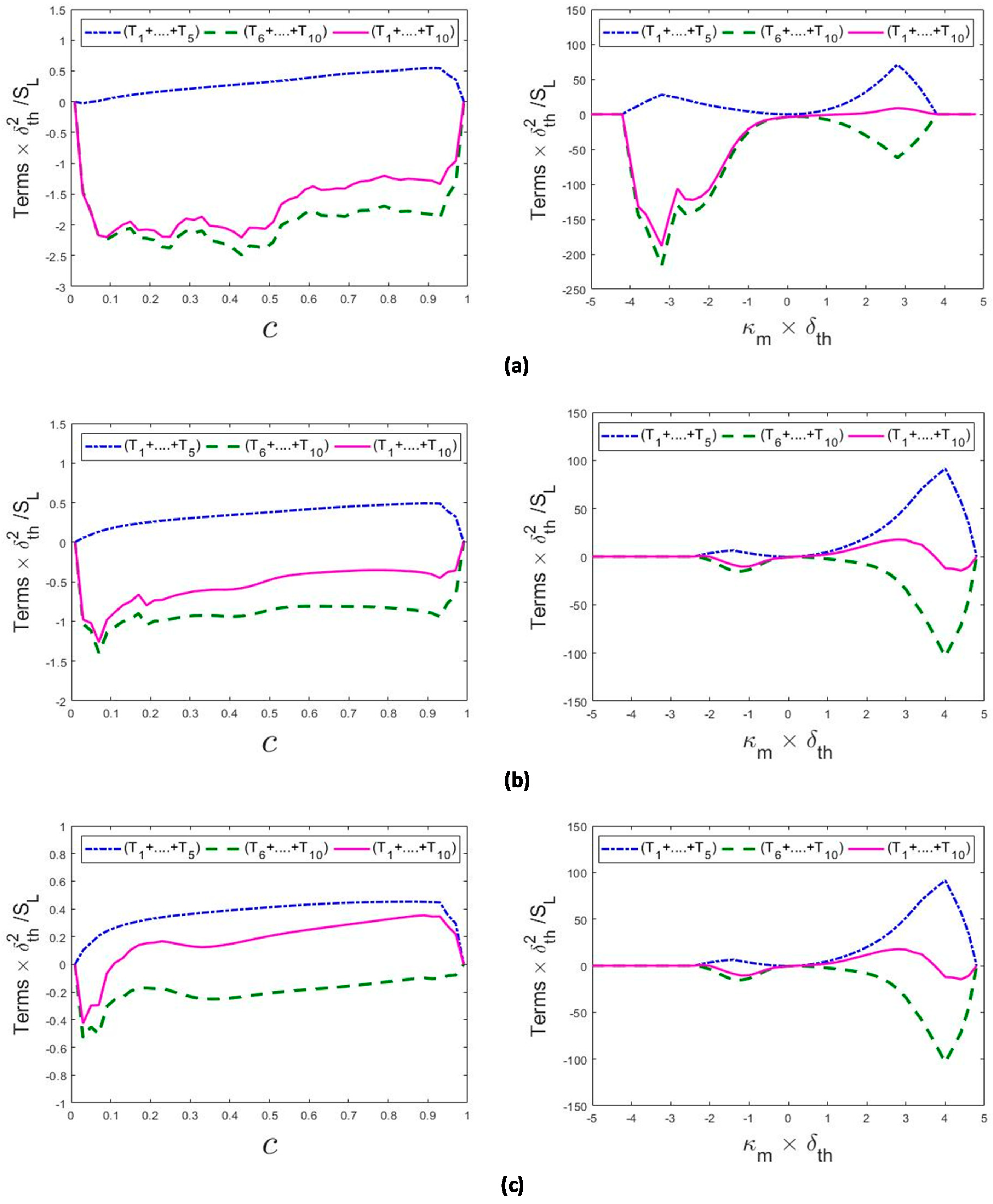
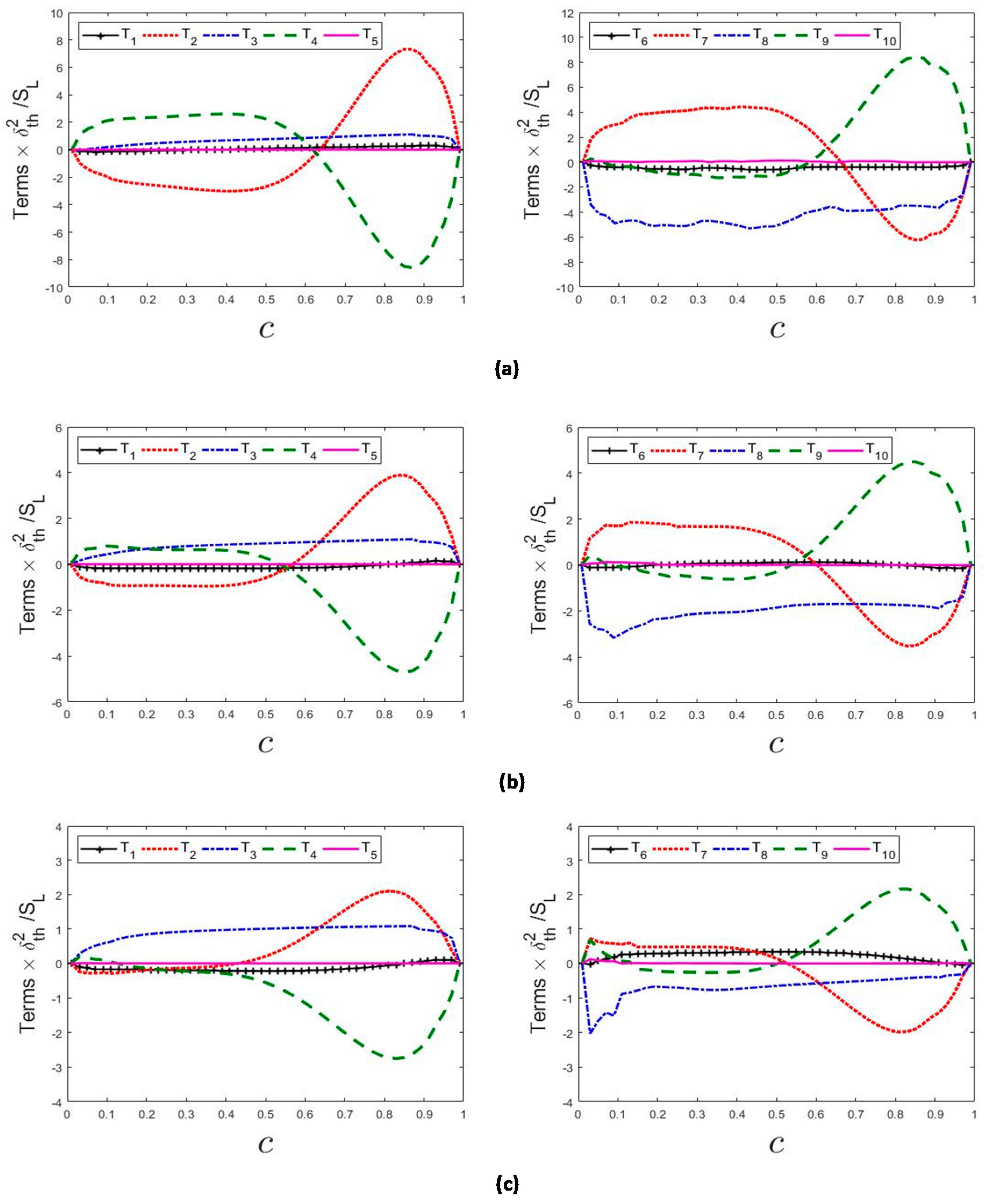
4.4. Overall Behaviour of the Terms in the Curvature Transport Equation

Figure 6 (left column) shows the normalised mean values of net fluid flow contributions ( T 1 + + T 5 ) × ( δ t h 2 / S L ) , flame propagation induced added contributions ( T 6 + + T 10 ) × ( δ t h 2 / S L ) and the total contribution ( T 1 + + T 10 ) × ( δ t h 2 / S L ) conditional upon the reaction progress variable c . As T 1 and T 5 have negligible contributions and T 4 nullifies T 2 , the net mean values of fluid motion terms ( T 1 + + T 5 ) × ( δ t h 2 / S L ) follow the statistical trend of the curvature flow stretching term T 3 × ( δ t h 2 / S L ) in all cases considered here. It is evident from Figure 6 (left column) that the net contribution of the added terms due to flame propagation ( T 6 + + T 10 ) × ( δ t h 2 / S L ) dominates over the net contribution of the terms ( T 1 + + T 5 ) × ( δ t h 2 / S L ) arising from fluid flow. The mean contributions of ( T 6 + + T 10 ) × ( δ t h 2 / S L ) and ( T 1 + + T 10 ) × ( δ t h 2 / S L ) remain negative throughout the flame front for all cases. This behaviour originates because the negative contributions of T 8 and T 9 dominate over the positive contribution arising from T 7 on the unburned gas side, whereas the combined negative contributions of T 7 and T 8 dominate over the positive contribution of T 9 on the product side of the flame front.
The statistical behaviours of the normalised mean values of flow contributions ( T 1 + + T 5 ) × ( δ t h 2 / S L ) , flame propagation induced contributions ( T 6 + + T 10 ) × ( δ t h 2 / S L ) and the total contribution ( T 1 + + T 10 ) × ( δ t h 2 / S L ) to the curvature transport, conditioned on curvature κ m are shown in Figure 6 (right column) for the c = 0.8 isosurface. It is clear from Figure 6 (right column) that the mean values of the flow contributions ( T 1 + + T 5 ) are negligible in comparison to the mean values of the overall added flame propagation terms ( T 6 + + T 10 ) in the negative curved locations, whereas the flow terms ( T 1 + + T 5 ) dominate over ( T 6 + + T 10 ) for positive curvatures in the L e = 0.8 case. However, in the L e = 1.0 and 1.2 cases, the net mean flame propagation contribution ( T 6 + + T 10 ) dominates over the mean contribution of the flow terms ( T 1 + + T 5 ) especially for the highly positive and negative curvatures. It can clearly be seen that the net contribution of the added terms induced by flame propagation conditional upon mean curvature κ m shows the same trend of the added strain rate and vorticity gradients terms T 9 and T 10 in the positively curved locations, whereas the added curvature stretching term T 8 determines the net mean behaviour of the added flame propagation contribution in the negatively curved zones. Thus, the net mean contribution of ( T 6 + + T 10 ) remains negative for both highly negative and positive curvatures. However, the magnitudes of mean negative ( T 6 + + T 10 ) in the positively curved zones are much greater than that in the negative curvatures in the L e = 1.0 and 1.2 cases. Just the opposite behaviour can be seen for the L e = 0.8 case, and the magnitude of the negative mean contribution of ( T 6 + + T 10 ) at the negatively curved locations is especially large in this case due to large negative values of T 8 . It is recalled that positivity (negativity) of ( T 1 + + T 10 ) leads to increasing positivity (negativity) of mean curvature. As a result of such an amplification of positive (negative) curvature values, the position of flame elements in the diagrams shown in the right column of Figure 6 moves towards the right (left) and the opposite happens for a damping of curvature values. In other words, Figure 6 implies a characteristic motion of the location of flame elements in this diagram until they either behave in a neutral manner or small-scale wrinkles with characteristic length scales considerably smaller than the inner cut-off scale are smoothed out by molecular diffusion effects.
Figure 6 (right column) shows that the mean contribution of ( T 1 + + T 10 ) remains strongly negative at negative values of κ m and mildly positive at positive values of κ m in the L e = 0.8 case. However, in the L e = 1.0 and 1.2 cases, the mean contribution of ( T 1 + + T 10 ) assumes negative values at highly positive and negative curved locations and positive values are obtained at moderately positive curved locations. The above findings indicate that the concavity of the negatively curved cusps, and the convexity of the positively curved bulges are promoted by the curvature transport in the L e = 0.8 case, which is further aided by the presence of high and low temperature (and thus burning rate) regions at positively and negatively curved regions, respectively. As a result, positively curved bulges with large radii of curvature and intermediate negatively curved cusps with small radii of curvature are likely to be observed in the L e = 0.8 case, which is consistent with the observations made from Figure 1 and the expected picture of the flame surface associated with L e < 1 . In the L e = 1.0 and 1.2 cases, the negative mean contribution of ( T 1 + + T 10 ) acts to reduce the convexity of the positively curved bulges. By contrast, the negative mean ( T 1 + + T 10 ) values at negatively curved locations in the L e = 1.0 and 1.2 cases act to increase the concavity of the negatively curved cusps. However, these structures are unstable and are eventually smoothed out due to increased S d at negatively curved locations. This effect is particularly strong in the L e = 1.2 case because of large temperature (and thus also burning rate) at the negatively curved regions.

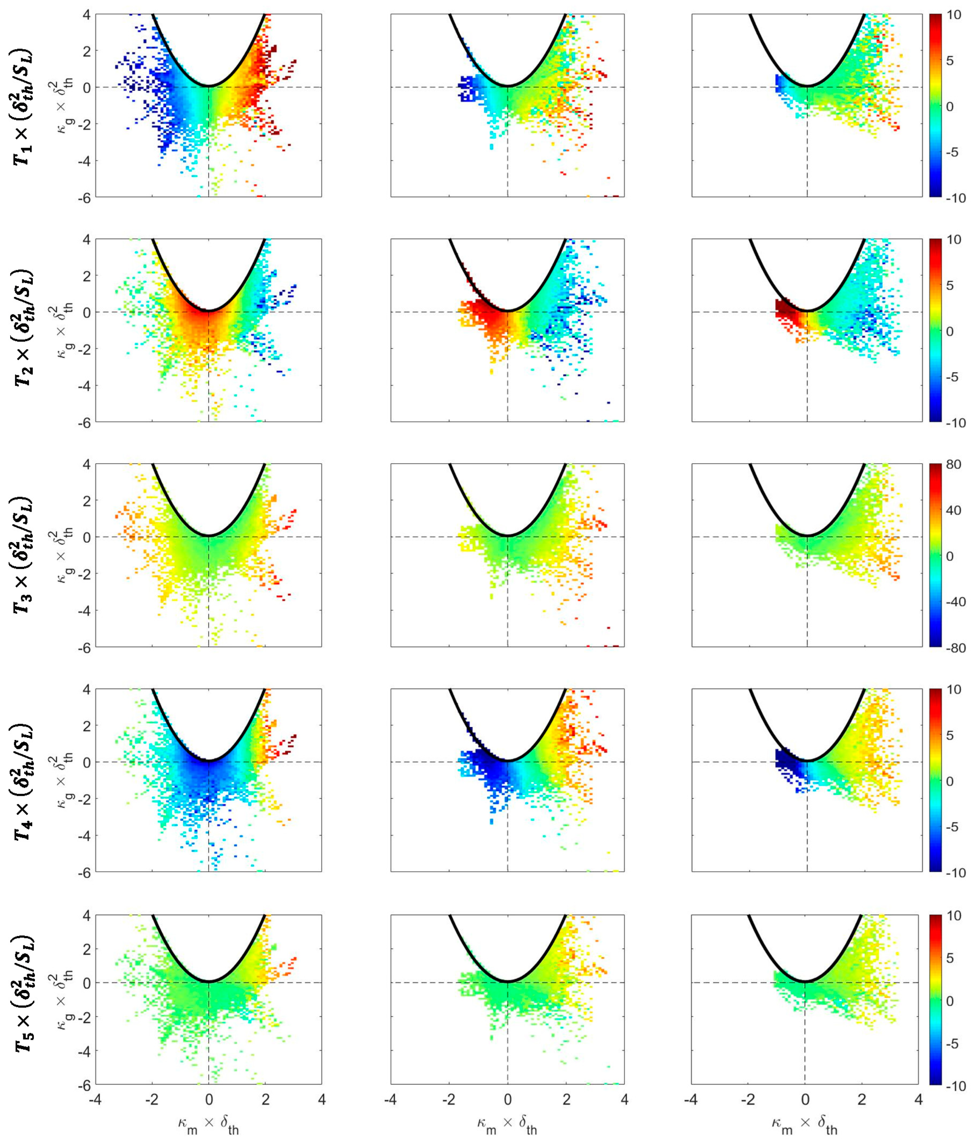
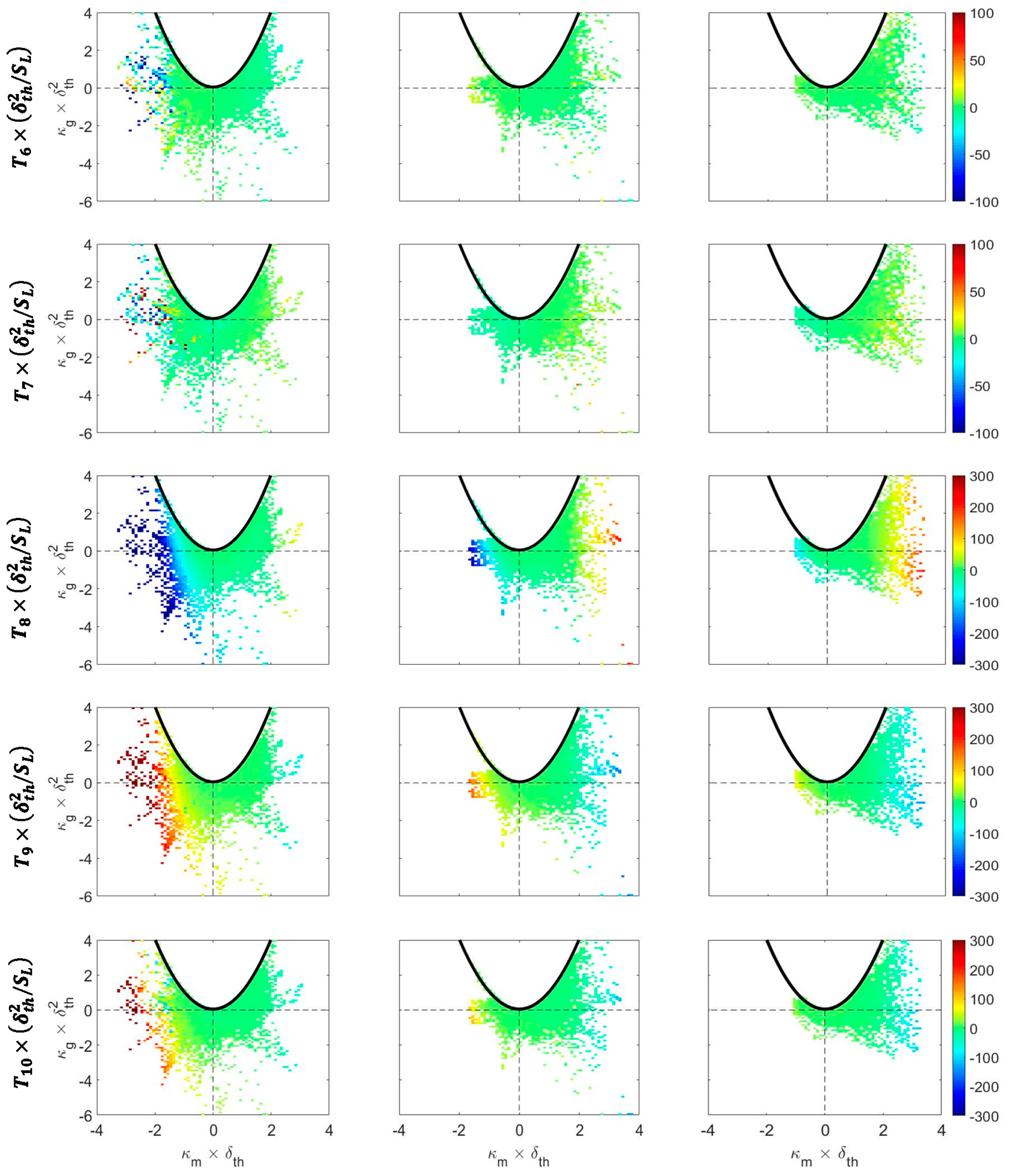
4.5. Relations of the Terms of the Curvature Transport Equation with Local Curvature

The mean values of T 1 5 × ( δ t h 2 / S L ) conditional on κ m × δ t h and κ g × δ t h 2 for the L e = 0.8 , 1.0 and 1.2 cases are shown in Figure 7 for the c = 0.8 isosurface. The corresponding variations of T 6 10 × ( δ t h 2 / S L ) conditional on κ m × δ t h and κ g × δ t h 2 on the c = 0.8 isosurface are shown in Figure 8 for these cases. Figure 7 indicates high magnitudes of T 1 and T 3 are mostly obtained for concave topologies on the flame surface for the L e = 0.8 case. The same trend is seen for T 1 , T 2 and T 4 in the L e = 1.0 and 1.2 flames. The large magnitudes of T 5 are associated with the cup convex flame topologies in all cases, and the magnitudes of these terms increase with decreasing Lewis number.
It is evident from Figure 8 that the terms T 6 10 in the L e = 0.8 case show high magnitudes for cup concave (i.e., κ m < 0 and κ g > 0 ) and saddle concave (i.e., κ m < 0 and κ g < 0 ) topologies. However, large magnitudes of these terms are mostly obtained for cup convex and saddle convex flame topologies in the L e = 1.0 and 1.2 cases. Moreover, large negative magnitudes of T 8 and large positive magnitudes of T 9 and T 10 can be discerned for small (both positive and negative) values of κ g for weakly negatively curved zones (i.e., κ m < 0 ) in the L e = 1.0 case.

4.6. Modelling Implications

It can be seen from Figure 4, Figure 5, Figure 6, Figure 7 and Figure 8 that the net flame propagation contribution to the curvature κ m transport plays significant roles for all flames considered here. This suggests that displacement speed S d is not only interlinked with curvature (i.e., a negative correlation exists between S d and κ m [32,33,34,35,36,37,38,39,40,41]) but it also affects flame wrikling through the curvature evolution. Moreover, it was demonstrated elsewhere [67,69,83,84,85,86] that the curvature κ m and its interrelation with displacement speed S d plays a key role in the Flame Surface Density (FSD) and scalar dissipation rate (SDR) transports. Furthermore, the analysis of curvature evolution also reveals that the displacement speed induced terms are principally responsible for the generation of negatively curved cusps in the flames with L e < 1 .

5. Conclusions

The effects of characteristic Lewis number on the statistical behaviours of the different terms of the curvature transport equation have been analysed based on three-dimensional compressible DNS data of spherically expanding turbulent premixed flames with L e = 0.8 , 1.0 and 1.2. The statistically spherical flames with L e = 0.8 , 1.0 and 1.2 had the same initial radius before they were allowed to interact with initially homogeneous isotropic decaying turbulence. It has been found that the flame surface area and volume-integrated burning rate increase with decreasing L e , which is consistent with several previous findings. The greater extent of flame wrinkling in the L e = 0.8 case is reflected in the wider range of both positive and negative curvatures than in the corresponding L e = 1.0 and 1.2 cases where the joint PDF remains almost symmetrical about κ m = 0 on the reactant side, but skews gradually toward positive values of κ m in the reaction and hot product zones. The PDFs of curvature for the L e = 0.8 case show higher probabilities of finding sharply negatively curved cusps than in the corresponding L e = 1.0 and 1.2 cases. Moreover, the saddle topologies have been found to be more frequent in the L e = 0.8 case than in the other cases considered in this analysis.
It has been found that the mean contributions of flame normal gradient of normal strain rate and the added strain rate due to flame displacement speed (i.e., T 2 and T 9 ) assume negative values (i.e., promote concavity of the flame surface) towards the unburned gas and positive values (i.e., promote convexity of the flame surface) on the burned gas side of the flame. By contrast, the mean contributions arising from flow strain rate gradient and the flame normal gradient of the added strain rate (i.e., T 4 and T 7 ) tend to promote positive and negative curvatures on reactant and product sides of the flame. The mean added curvature stretch term T 8 exhibits negative mean values throughout the flame, while the curvature flow stretching term T 3 remains positive throughout the flame front.
The mean added curvature stretch term T 8 conditional on curvature shows different behaviour in response to the changes in L e . The added curvature stretch term T 8 shows negative mean values for κ m < 0 and negligible mean value of T 8 is obtained for κ m > 0 in the L e = 0.8 case but positive (negative) mean values of T 8 are obtained for positive (negative) κ m values in the L e = 1.0 and 1.2 cases. The mean value of curvature flow stretching term T 3 remains positive for both κ m > 0 and κ m < 0 but the magnitude of T 3 associated with κ m < 0 increases significantly with decreasing L e . The terms due to normal gradient of added strain rate T 9 and the curl of added vorticity T 10 assume positive (negative) values for negative (positive) κ m values. The net mean contribution of the terms arising from flame propagation (i.e., ( T 6 + + T 10 ) ) dominates over the net mean contribution of the terms due to background fluid motion (i.e., ( T 1 + + T 5 ) ) for the negatively curved locations but the opposite behaviour has been observed for the positively curved zones in the L e = 0.8 case. However, in the L e = 1.0 and 1.2 cases the net mean flame propagation contribution ( T 6 + + T 10 ) dominates over the mean contribution of the flow terms ( T 1 + + T 5 ) especially for high magnitudes of κ m . For the L e = 1.0 and 1.2 cases, the net mean contribution of ( T 1 + + T 10 ) remains negative for high positive curvatures but this contribution assumes weak negative values for negatively curved regions. By contrast, in the L e = 0.8 case, the net mean contribution of ( T 1 + + T 10 ) assumes negative values for κ m < 0 and mild positive values are obtained for κ m > 0 , which is indicative of promoting sharply negatively curved cusps and positively curved bulges with large radii of curvature. This tendency is further augmented by high temperatures (also burning rates) in the positively curved and low temperatures (also burning rates) in the negatively curved regions in the L e = 0.8 case, which is expected in the presence of thermo-diffusive instability. By contrast, highly positively curved bulges are not promoted in the L e = 1.0 and 1.2 cases, and weak negative mean contributions of ( T 1 + + T 10 ) at the negatively curved zones tend to produce negatively curved cusps which are eventually smoothed by large values of S d in these regions. Thus, flame propagation tends to smoothen the flame wrinkles induced by turbulence in the L e = 1.0 and 1.2 cases and this effect is stronger in the L e = 1.2 case due to high temperature (and thus high reaction rate) at the negatively curved regions. Furthermore, it has been found that flame propagation plays a pivotal role in the curvature evolution irrespective of the characteristic Lewis number and thus the interrelation between displacement speed and curvature needs to be explicitly accounted for in the context of FSD and SDR closures, especially in order to predict thermo-diffusive instability effects for L e < 1 flames. This model development along with further analysis of curvature evolution using detailed chemistry and transport-based DNS data will form the basis of further investigations.

Author Contributions

Conceptualization, N.C. and M.K.; simulation, M.K.; Postprocessing code development, A.A., N.C.; formal analysis, A.A., N.C.; writing—original draft preparation, A.A., N.C.; writing—review and editing, N.C., M.K.; visualization, A.A., N.C. M.K.; supervision, N.C.; funding acquisition, N.C., M.K.

Funding

This research was funded by Engineering and Physical Sciences Research Council (EPSRC) (EP/K025163/1) and the German Research Foundation (DFG, KL1456/5-1).

Acknowledgments

We received computational support from ARCHER, Rocket High Performance Computing and Gauss Centre for Supercomputing (grant: pn69ga).

Conflicts of Interest

The authors declare no conflict of interest.

References

  1. Abdel-Gayed, R.G.; Al-Khishali, K.J.; Bradley, D. Turbulent burning velocities and flame straining in explosions. Proc. R. Soc. Lond. A 1984, 391, 393–414. [Google Scholar] [CrossRef]
  2. Beretta, G.P.; Rashidi, M.; Keck, J.C. Turbulent flame propagation and combustion in spark ignition engines. Combust. Flame 1983, 52, 217–245. [Google Scholar] [CrossRef] [Green Version]
  3. Bradley, D.; Gaskell, P.H.; Gu, X.J. Burning velocities, Markstein lengths, and flame quenching for spherical methane-air flames: A computational study. Combust. Flame 1996, 104, 176–198. [Google Scholar] [CrossRef]
  4. Renou, B.; Boukhalfa, A.; Puechberty, D.; Trinit’e, M. Local scalar flame properties of freely propagating premixed turbulent flames at various Lewis numbers. Combust. Flame 2000, 123, 507–521. [Google Scholar] [CrossRef]
  5. Haq, M.Z.; Sheppard, C.G.W.; Woolley, R.; Greenhalgh, D.A.; Lockett, R.D. Wrinkling and curvature of laminar and turbulent premixed flames. Combust. Flame 2002, 131, 1–15. [Google Scholar] [CrossRef]
  6. Bradley, D.; Haq, M.Z.; Hicks, R.A.; Kitagawa, T.; Lawes, M.; Sheppard, C.G.W.; Woolley, R. Turbulent burning velocity, burned gas distribution, and associatedflame surface definition. Combust. Flame 2002, 133, 415–430. [Google Scholar] [CrossRef]
  7. Lawes, M.; Ormsby, M.P.; Sheppard, C.G.W.; Woolley, R. The turbulent burning velocity of iso-octane/air mixtures. Combust. Flame 2012, 159, 1949–1959. [Google Scholar] [CrossRef] [Green Version]
  8. Chaudhuri, S.; Wu, F.; Zhu, D.; Law, C.K. Flame speed and self-similar propagation of expanding turbulent premixed flames. Phys. Rev. Lett. 2012, 108, 044503. [Google Scholar] [CrossRef]
  9. Akkerman, V.; Chaudhuri, S.; Law, C.K. Accelerative propagation and explosion triggering by expanding turbulent premixed flames. Phys. Rev. E 2013, 87, 23008. [Google Scholar] [CrossRef]
  10. Pope, S.B.; Cheng, W.K. Statistical calculations of spherical turbulent flames. Proc. Combust. Inst. 1986, 21, 1473–1481. [Google Scholar]
  11. Baum, M.; Poinsot, T. Effects of mean flow on premixed flame ignition. Combust. Sci. Technol. 1995, 106, 19–39. [Google Scholar] [CrossRef]
  12. Poinsot, T.; Candel, S.; Trouve, A. Applications of direct numerical simulation to premixed turbulent combustion. Prog. Energy Combust. Sci. 1995, 21, 531–576. [Google Scholar] [CrossRef]
  13. Schmid, H.-P.; Habisreuther, P.; Leuckel, W. A model for calculating heat release in premixed turbulent flames. Combust. Flame 1998, 113, 79–91. [Google Scholar] [CrossRef]
  14. Nwagwe, I.K.; Weller, H.G.; Tabor, G.R.; Gosman, A.D.; Lawes, M.; Sheppard, C.G.W.; Wooley, R. Measurements and large eddy simulations of turbulent premixed flame kernel growth. Proc. Combust. Inst. 2000, 28, 59–65. [Google Scholar] [CrossRef]
  15. Jenkins, K.W.; Cant, R.S. Curvature effects on flame kernels in a turbulent environment. Proc. Combust. Inst. 2002, 29, 2023–2029. [Google Scholar] [CrossRef]
  16. Tabor, G.; Weller, H.G. Large eddy simulation of premixed turbulent combustion using flame surface wrinkling model. Flow Turbul. Combust. 2004, 72, 1–27. [Google Scholar] [CrossRef]
  17. van Oijen, J.A.; Groot, G.R.A.; Bastiaans, R.J.M.; de Goey, L.P.H. A flamelet analysis of the burning velocity of premixed turbulent expanding flames. Proc. Combust. Inst. 2005, 30, 657–664. [Google Scholar] [CrossRef]
  18. Gashi, S.; Hult, J.; Jenkins, K.W.; Chakraborty, N.; Cant, R.S.; Kaminski, C.F. Curvature and Wrinkling of Premixed Flame Kernels-Comparisons of OH PLIF and DNS data. Proc. Combust. Inst. 2005, 30, 809–817. [Google Scholar] [CrossRef]
  19. Thevenin, D. Three-dimensional direct simulations and structure of expanding turbulent methane flames. Proc. Combust. Inst. 2005, 30, 629–637. [Google Scholar] [CrossRef]
  20. Klein, M.; Chakraborty, N.; Jenkins, K.W.; Cant, R.S. Effects of initial radius on the propagation of premixed flame kernels in a turbulent environment. Phys. Fluids 2006, 18, 055102. [Google Scholar] [CrossRef]
  21. Jenkins, K.W.; Klein, M.; Chakraborty, N.; Cant, R.S. Effects of strain rate and curvature on the propagation of a spherical flame kernel in the thin-reactionzones regime. Combust. Flame 2006, 145, 415–434. [Google Scholar] [CrossRef]
  22. Klein, M.; Chakraborty, N.; Cant, R.S. Effects of turbulence on self-sustained combustion in premixed flame kernels: A direct numerical simulation (DNS) study. Flow Turbul. Combust. 2008, 81, 583–607. [Google Scholar] [CrossRef]
  23. Hult, J.; Gashi, S.; Chakraborty, N.; Klein, M.; Jenkins, K.W.; Cant, R.S.; Kaminski, C. Measurement of Flame Surface Density for Turbulent Premixed Flames using PLIF and DNS. Proc. Combust. Inst. 2007, 31, 1319–1326. [Google Scholar] [CrossRef]
  24. Chakraborty, N.; Klein, M.; Cant, R.S. Stretch rate effects on displacement speed in turbulent premixed flame kernels in the thin reaction zones regime. Proc. Combust. Inst. 2007, 31, 1385–1392. [Google Scholar] [CrossRef]
  25. Dunstan, T.D.; Jenkins, K.W. Flame surface density distribution in turbulent flame kernels during the early stages of growth. Proc. Combust. Inst. 2009, 32, 1427–1434. [Google Scholar] [CrossRef]
  26. Dunstan, T.D.; Jenkins, K.W. The effects of hydrogen substitution on turbulent premixed methane-air kernels using direct numerical simulation. Int. J. Hydrogen Energy 2009, 34, 8389–8404. [Google Scholar] [CrossRef]
  27. Chakraborty, N.; Rogerson, J.W.; Swaminathan, N. The scalar gradient alignment statistics of flame kernels and its modelling implications for turbulent premixed combustion. Flow Turbul. Combust. 2010, 85, 25–55. [Google Scholar] [CrossRef]
  28. Lecocq, G.; Richard, S.; Colin, O.; Vervisch, L. Hybrid presumed PDF and flame surface density approaches for large-eddy simulation of premixed turbulent combustion. part 2: Early flame development after sparking. Combust. Flame 2011, 158, 1215–1226. [Google Scholar] [CrossRef]
  29. Colin, O.; Truffin, K. A spark ignition model for large eddy simulation based on an FSD transport equation (ISSIM-LES). Proc. Combust. Inst. 2011, 33, 3097–3104. [Google Scholar] [CrossRef]
  30. Ahmed, I.; Swaminathan, N. Simulation of spherically expanding turbulent premixed flames. Combust. Sci.Technol. 2013, 185, 1509–1540. [Google Scholar] [CrossRef]
  31. Ahmed, I.; Swaminathan, N. Simulation of turbulent explosion of hydrogen-air mixtures. Int. J. Hydrogen Energy 2014, 39, 9562–9572. [Google Scholar] [CrossRef]
  32. Peters, N.; Terhoeven, P.; Chen, J.H.; Echekki, T. Statistics of flame displacement speeds from computations of 2-D unsteady methane-air flames. Proc. Combust. Inst. 1998, 27, 833–839. [Google Scholar] [CrossRef] [Green Version]
  33. Echekki, T.; Chen, J.H. Analysis of the contributions of curvature to premixed flame propagation. Combust. Flame 1999, 118, 308–311. [Google Scholar] [CrossRef]
  34. Chen, J.H.; Im, H.G. Correlation of flame speed with stretch in turbulent premixed Methane/Air flames. Proc. Combust. Inst. 1998, 27, 819–826. [Google Scholar] [CrossRef]
  35. Chen, J.H.; Im, H.G. Stretch effects on the burning velocity of turbulent premixed Hydrogen/Air flames. Proc. Combust. Inst. 2000, 28, 211–218. [Google Scholar] [CrossRef]
  36. Hawkes, E.R.; Chen, J.H. Direct numerical simulation of hydrogen-enriched lean premixed methane air flames. Combust. Flame 2004, 138, 242–258. [Google Scholar] [CrossRef]
  37. Hawkes, E.R.; Chen, J.H. Evaluation of models for flame stretch due to curvature in the thin reaction zones regime. Proc. Combust. Inst. 2005, 30, 647–655. [Google Scholar] [CrossRef]
  38. Chakraborty, N.; Cant, S. Unsteady effects of strain rate and curvature on turbulent premixed flames in inlet-outlet configuration. Combust. Flame 2004, 137, 129–147. [Google Scholar] [CrossRef]
  39. Chakraborty, N.; Cant, R.S. Influence of Lewis number on curvature effects in turbulent premixed flame propagation in the thin reaction zones regime. Phys. Fluids 2005, 17, 105105. [Google Scholar] [CrossRef]
  40. Chakraborty, N. Comparison of displacement speed statistics of turbulent premixed flames in the regimes representing combustion in corrugated flamelets and thin reaction zones. Phys. Fluids 2007, 19, 105109. [Google Scholar] [CrossRef]
  41. Han, I.; Huh, K.Y. Roles of displacement speed on evolution of flame surface density for different turbulent intensities and Lewis numbers in turbulent premixed combustion. Combust. Flame 2008, 152, 194–205. [Google Scholar] [CrossRef]
  42. Rutland, C.; Trouvé, A. Direct Simulations of premixed turbulent flames with nonunity Lewis numbers. Combust. Flame 1993, 94, 41–57. [Google Scholar] [CrossRef]
  43. Chakraborty, N.; Cant, R.S. Effects of strain rate and curvature on surface density function transport in turbulent premixed flames in the thin reaction zones regime. Phys. Fluids 2005, 17, 065108. [Google Scholar] [CrossRef]
  44. Chakraborty, N.; Klein, M. Influence of Lewis number on the Surface Density Function transport in the thin reaction zones regime for turbulent premixed flames. Phys. Fluids 2008, 20, 065102. [Google Scholar] [CrossRef]
  45. Chakraborty, N.; Klein, M. Effects of global flame curvature on surface density function transport in turbulent premixed flame kernels in the thin reaction zone regime. Proc. Combust. Inst. 2009, 32, 1435–1443. [Google Scholar] [CrossRef]
  46. Sandeep, A.; Proch, F.; Kempf, A.M.; Chakraborty, N. Statistics of strain rates and Surface Density Function in a flame-resolved high-fidelity simulation of a turbulent premixed bluff body burner. Phys. Fluids 2018, 30, 065101. [Google Scholar] [CrossRef]
  47. Chakraborty, N.; Hawkes, E.R.; Chen, J.H.; Cant, R.S. Effects of strain rate and curvature on Surface Density Function transport in turbulent premixed CH4-air and H2-air flames: A comparative study. Combust. Flame 2008, 154, 259–280. [Google Scholar] [CrossRef]
  48. Klein, M.; Alwazzan, D.; Chakraborty, N. A Direct Numerical Simulation analysis of pressure variation in turbulent premixed Bunsen burner flames-Part 1: Scalar gradient and strain rate statistics. Comput. Fluids 2018. [Google Scholar] [CrossRef]
  49. Klein, M.; Alwazzan, D.; Chakraborty, N. A Direct Numerical Simulation analysis of pressure variation in turbulent premixed Bunsen burner flames-Part 2: Surface Density Function transport statistics. Comput. Fluids 2018. [Google Scholar] [CrossRef]
  50. Reddy, H.; Abraham, J. Two-dimensional direct numerical simulation evaluation of the flame-surface density model for flames developing from an ignition kernel in lean methane/air mixtures under engine conditions. Phys. Fluids 2012, 24, 105108. [Google Scholar] [CrossRef]
  51. Pope, S.B. The evolution of surfaces in turbulence. Int. J. Eng. Sci. 1988, 26, 445–469. [Google Scholar] [CrossRef]
  52. Dopazo, C.; Martin, J.; Cifuentes, L.; Hierro, J. Strain, rotation and curvature of non-material propagating iso-scalar surfaces in homogeneous turbulence. Flow Turbul. Combust. 2018. [Google Scholar] [CrossRef]
  53. Cifuentes, L.; Dopazo, C.; Karichedu, A.; Chakraborty, N.; Kempf, A.M. Analysis of flame curvature evolution in a turbulent premixed bluff Body burner. Phys. Fluids 2018, 30, 095101. [Google Scholar] [CrossRef]
  54. Sivashinsky, G.I. Diffusional-thermal theory of cellular flames. Combust. Sci. Technol. 1977, 16, 137–146. [Google Scholar] [CrossRef]
  55. Clavin, P.; Williams, F.A. Effects of molecular diffusion and thermal expansion on the structure and dynamics of turbulent premixed flames in turbulent flows of large scale and small intensity. J. Fluid Mech. 1982, 128, 251–282. [Google Scholar] [CrossRef]
  56. Ashurst, W.T.; Peters, N.; Smooke, M.D. Numerical simulation of turbulent flame structure with non-unity Lewis number. Combust. Sci. Technol. 1987, 53, 339–375. [Google Scholar] [CrossRef]
  57. Haworth, D.C.; Poinsot, T.J. Numerical simulations of Lewis number effects in turbulent premixed flames. J. Fluid Mech. 1992, 244, 405–436. [Google Scholar] [CrossRef]
  58. Trouvé, A.; Poinsot, T. The evolution equation for flame surface density in turbulent premixed combustion. J. Fluid Mech. 1994, 278, 1–31. [Google Scholar] [CrossRef]
  59. Dopazo, C.; Cifuentes, L.; Chakraborty, N. Vorticity budgets in premixed combusting turbulent flows at different Lewis numbers. Phys. Fluids 2017, 29, 045106. [Google Scholar] [CrossRef]
  60. Dopazo, C.; Cifuentes, L.; Martin, J.; Jimenez, C. Strain rates normal to approaching isoscalar surfaces in a turbulent premixed flame. Combust. Flame 2015, 162, 1729–1736. [Google Scholar] [CrossRef]
  61. Dopazo, C.; Cifuentes, L.; Alwazzan, D.; Chakraborty, N. Influence of the Lewis number on effective strain rates in weakly turbulent premixed combustion. Combust. Sci. Technol. 2018, 190, 591–614. [Google Scholar] [CrossRef]
  62. Chakraborty, N.; Kolla, H.; Sankaran, R.; Hawkes, E.R.; Chen, J.H.; Swaminathan, N. Determination of three-dimensional quantities related to scalar dissipation rate and its transport from two-dimensional measurements: Direct Numerical Simulation based validation. Proc. Combust. Inst. 2013, 34, 1151–1162. [Google Scholar] [CrossRef]
  63. Lipatnikov, A.N.; Nishiki, S.; Hasegawa, T. A direct numerical study of vorticity transformation in weakly turbulent premixed flames. Phys. Fluids 2014, 26, 105104. [Google Scholar] [CrossRef]
  64. Gao, Y.; Chakraborty, N.; Klein, M. Assessment of sub-grid scalar flux modelling in premixed flames for Large Eddy Simulations: A-priori Direct Numerical Simulation. Eur. J. Mech. Fluids-B 2015, 52, 97–108. [Google Scholar] [CrossRef]
  65. Papapostolou, V.; Wacks, D.H.; Klein, M.; Chakraborty, N.; Im, H.G. Enstrophy transport conditional on local flow topologies in different regimes of premixed turbulent combustion. Sci. Rep. 2017, 7, 11545. [Google Scholar] [CrossRef] [PubMed]
  66. Klein, M.; Kasten, C.; Chakraborty, N.; Mukhadiyev, N.; Im, H.G. Turbulent scalar fluxes in Hydrogen-Air premixed flames at low and high Karlovitz numbers. Combust. Theory Model. 2018, 22, 1033–1048. [Google Scholar] [CrossRef]
  67. Gao, Y.; Chakraborty, N. Modelling of Lewis Number dependence of Scalar dissipation rate transport for Large Eddy Simulations of turbulent premixed combustion. Numer. Heat Trans. A 2016, 69, 1201–1222. [Google Scholar] [CrossRef]
  68. Lai, J.; Chakraborty, N. Effects of Lewis Number on head on quenching of turbulent premixed flame: A Direct Numerical Simulation analysis. Flow Turbul. Combust. 2016, 96, 279–308. [Google Scholar] [CrossRef]
  69. Gao, Y.; Minamoto, Y.; Tanahashi, M.; Chakraborty, N. A priori assessment of scalar dissipation rate closure for Large Eddy Simulations of turbulent premixed combustion using a detailed chemistry Direct Numerical Simulation database. Combust. Sci. Technol. 2016, 188, 1398–1423. [Google Scholar] [CrossRef]
  70. Lai, J.; Klein, M.; Chakraborty, N. Direct Numerical Simulation of head-on quenching of statistically planar turbulent premixed methane-air flames using a detailed chemical mechanism. Flow Turbul. Combust. 2018, 101, 1073–1091. [Google Scholar] [CrossRef]
  71. Jenkins, K.W.; Cant, R.S. DNS of turbulent flame kernels. In Proceedings of the 2nd AFOSR Conference on DNS and LES; Liu, C., Sakell, L., Beautner, T., Eds.; Kluwer Academic Publishers: Dordrecht, The Netherlands, 1999; pp. 192–202. [Google Scholar]
  72. Muppala, S.R.; Aluri, N.K.; Dinkelacker, F.; Leipertz, A. Development of an Algebraic Reaction rate approach for the Numerical Calculation of Turbulent Premixed Methane, Ethylene and Propane/air flames at Pressures up to 1.0 MPa. Combust. Flame 2005, 140, 257–266. [Google Scholar] [CrossRef]
  73. Kobayashi, H.; Tamura, H.; Maruta, K.; Nikola, T.; Williams, F.A. Burning velocity of turbulent premixed flames in a high-pressure environment. Proc. Combust. Inst. 1996, 26, 389–396. [Google Scholar] [CrossRef]
  74. Wray, A.A. Minimal Storage Time Advancement Schemes for Spectral Methods; NASA Ames Research Center: Mountain View, CA, USA, 1990; Unpublished work.
  75. Poinsot, T.; Lele, S.K. Boundary conditions for direct simulation of compressible viscous flows. J. Comp. Phys. 1992, 101, 104–129. [Google Scholar] [CrossRef]
  76. Rogallo, R.S. Numerical Experiments in Homogeneous Turbulence; NASA Technical Memorandum 81315; NASA Ames Research Center: Mountain View, CA, USA, 1981.
  77. Pope, S.B. Turbulent Flows; Cambridge University Press: Cambridge, UK, 2000. [Google Scholar]
  78. Peters, N. Turbulent Combustion, Cambridge Monograph on Mechanics; Cambridge University Press: Cambridge, UK, 2000. [Google Scholar]
  79. Dopazo, C.; Martin, J.; Hierro, J. Local geometry of isoscalar surfaces. Phys. Rev. E 2007, 76, 056316. [Google Scholar] [CrossRef]
  80. Hartung, G.; Hult, J.; Kaminski, C.F.; Rogerson, J.W.; Swaminathan, N. Effect of heat release on turbulence and scalar-turbulence interaction in premixed combustion. Phys. Fluids 2008, 20, 035110. [Google Scholar] [CrossRef]
  81. Chakraborty, N.; Swaminathan, N. Influence of Damköhler number on turbulence-scalar interaction in premixed flames, Part I: Physical Insight. Phys. Fluids 2007, 19, 045103. [Google Scholar] [CrossRef]
  82. Chakraborty, N.; Klein, M.; Swaminathan, N. Effects of Lewis number on reactive scalar gradient alignment with local strain rate in turbulent premixed flames. Proc. Combust. Inst. 2009, 32, 1409–1417. [Google Scholar] [CrossRef]
  83. Chakraborty, N.; Cant, R.S. A-Priori Analysis of the curvature and propagation terms of the Flame Surface Density transport equation for Large Eddy Simulation. Phys. Fluids 2007, 19, 105101. [Google Scholar] [CrossRef]
  84. Chakraborty, N.; Cant, R.S. Direct Numerical Simulation analysis of the Flame Surface Density transport equation in the context of Large Eddy Simulation. Proc. Combust. Inst. 2009, 32, 1445–1453. [Google Scholar] [CrossRef]
  85. Gao, Y.; Chakraborty, N.; Swaminathan, N. Local strain rate and curvature dependences of scalar dissipation rate transport in turbulent premixed flames: A Direct Numerical Simulation analysis. J. Combust. 2014, 2014, 280671. [Google Scholar] [CrossRef]
  86. Gao, Y.; Chakraborty, N.; Swaminathan, N. Scalar dissipation rate transport and its modelling for Large Eddy Simulations of turbulent premixed combustion. Combust. Sci. Technol. 2015, 187, 362–383. [Google Scholar] [CrossRef]
Figure 1. Instantaneous isosurfaces of reaction progress variable c = 0.8 colored by non-dimensional temperature 𝜃 (a), local values of normalised curvature κ m × δ t h (b) and normalised Gauss curvature κ g × δ t h 2 (c) for cases with Le = 0.8, 1.0 and 1.2 (1st–3rd row).
Fluids 04 00012 g001
Figure 2. Probability density functions (PDFs) of κ m × δ t h on (ae) c = 0.1 , 0.3, 0.5, 0.7 and 0.9 isosurfaces for Le = 0.8, 1.0 and 1.2.
Fluids 04 00012 g002
Figure 3. Joint PDF (coloured from blue to dark red) between normalised curvature κ m × δ t h and normalised Gauss curvature κ g × δ t h 2 for c = 0.3 , 0.5, 0.7 and 0.9 (1st–4th column) isosurfaces for cases Le = 0.8,1.0 and 1.2 (1st–3rd row).
Fluids 04 00012 g003
Figure 4. Profiles of the normalised mean values of the fluid flow induced terms (i.e., T 1 5 × δ t h 2 / S L ) (left column) and flame propagation induced terms (i.e., T 6 10 × δ t h 2 / S L ) (right column) of the curvature transport equation conditional upon c for cases (ac) Le = 0.8, 1.0 and 1.2.
Fluids 04 00012 g004
Figure 5. Profiles of the normalised mean values of the fluid flow induced terms (i.e., T 1 5 × δ t h 2 / S L ) (left column) and flame propagation induced terms (i.e., T 6 10 × δ t h 2 / S L ) (right column) of the curvature transport equation conditional upon normalised curvature κ m × δ t h on the c = 0.8 isosurface for cases (ac) Le = 0.8, 1.0 and 1.2.
Fluids 04 00012 g005
Figure 6. Profiles of normalised mean values of the flow contributions ( T 1 + + T 5 ) × ( δ t h 2 / S L ) , flame propagation induced contributions ( T 6 + + T 10 ) × ( δ t h 2 / S L ) and the total contribution ( T 1 + + T 10 ) × ( δ t h 2 / S L ) to the curvature transport, conditioned on the reaction progress variable c (left column) and normalised curvature κ m × δ t h on the c = 0.8 isosurface (right column) for cases (ac) Le = 0.8, 1.0 and 1.2.
Fluids 04 00012 g006
Figure 7. Variations of the mean values of T 1 5 × ( δ t h 2 / S L ) (1st–5th row) conditional on κ m × δ t h and κ g × δ t h 2 for Le = 0.8, 1.0 and 1.2 flames (1st–3rd column) for c = 0.8 isosurface.
Fluids 04 00012 g007
Figure 8. Variations of the mean values of T 6 10 × ( δ t h 2 / S L ) (1st–5th row) conditional on κ m × δ t h and κ g × δ t h 2 for Le = 0.8, 1.0 and 1.2 flames (1st–3rd column) for c = 0.8 isosurface.
Fluids 04 00012 g008
Table 1. Nomenclature associated with the velocity gradient tensor v i , j c of an iso-surface element.
DescriptionTerm
Total strain rate tensor S i j c = 0.5 ( v i c / x j + v j c / x i )
Total rotation rate tensor W i j c = 0.5 ( v i c / x j v j c / x i )
Flow strain rate tensor S i j = 0.5 ( u i / x j + u j / x i )
Flow rotation rate tensor W i j = 0.5 ( u i / x j u j / x i )
Added strain rate tensor S i j a =   0.5 [ ( S d / x j ) n i + ( S d / x i ) n j ] Space   dependence   of   S d +   S d 0.5 ( n i / x j + n j / x i ) Propagating   curved   iso c
Added rotation rate tensor W i j a =   0.5 [ ( S d / x j ) n i ( S d / x i ) n j ] Space   dependence   of   S d +   S d 0.5 ( n i / x j n j / x i ) Propagating   curved   iso c
Table 2. Description of the various terms in the curvature transport Equation (9).
Flow TermsAdded Terms
TermsDescriptionTermsDescription
T 1 Contribution due to curvature and flow normal strain rate correlation T 6 Term due to curvature and added normal strain rate correlation
T 2 Contribution due to flow normal strain rate normal variation T 7 Contribution due to added normal strain rate normal variation
T 3 Flow stretching term T 8 Added stretching term
T 4 Contribution of flow strain rate gradients T 9 Contribution of added strain rate gradients
T 5 Contribution of flow vorticity curl T 10 Contribution of added vorticity curl
Table 3. Lewis number dependence of the normalised volume-integrated burning rate Ω T / Ω L and flame surface area A T / A L when the statistics were extracted.
LeΩTLAT/AL
0.813.7513.22
1.06.867.30
1.23.864.66

