Role of Surface-Layer Coherent Eddies in Potential Vorticity Transport in Quasigeostrophic Turbulence Driven by Eastward Shear


1
School of Marine and Atmospheric Sciences, Stony Brook University, Stony Brook, NY 11794, USA
2
Lamont-Doherty Earth Observatory, Columbia University, Palisades, NY 10964, USA
*
Author to whom correspondence should be addressed.
Fluids 2020, 5(1), 2; https://doi.org/10.3390/fluids5010002
Submission received: 1 November 2019
/
Revised: 10 December 2019
/
Accepted: 18 December 2019
/
Published: 22 December 2019
(This article belongs to the Special Issue Lagrangian Transport in Geophysical Fluid Flows)
Abstract
:The transport by materially coherent surface-layer eddies was studied in a two-layer quasigeostrophic model driven by eastward mean shear. The coherent eddies were identified by closed contours of the Lagrangian-averaged vorticity deviation obtained from Lagrangian particles advected by the flow. Attention was restricted to eastward mean flows, but a wide range of flow regimes with different bottom friction strengths, layer thickness ratios, and background potential vorticity (PV) gradients were otherwise considered. It was found that coherent eddies become more prevalent and longer-lasting as the strength of bottom drag increases and the stratification becomes more surface-intensified. The number of coherent eddies is minimal when the shear-induced PV gradient is 10–20 times the planetary PV gradient and increases for both larger and smaller values of the planetary PV gradient. These coherent eddies, with an average core radius close to the deformation radius, propagate meridionally with a preference for cyclones to propagate poleward and anticyclones to propagate equatorward. The meridional propagation preference of the coherent eddies gives rise to a systematic upgradient PV transport, which is in the opposite direction as the background PV transport and not captured by standard Lagrangian diffusivity estimates. The upgradient PV transport by coherent eddy cores is less than 15% of the total PV transport, but the PV transport by the periphery flow induced by the PV inside coherent eddies is significant and downgradient. These results clarify the distinct roles of the trapping and stirring effect of coherent eddies in PV transport in geophysical turbulence.
1. Introduction
Ocean mesoscale eddies play an important role in transport and mixing in the ocean, and can affect wide range of oceanographic phenomena, including the stratification and overturning circulation in the Southern Ocean [1,2,3,4,5], eastern boundary currents [6,7,8,9,10,11,12,13], nutrient cycling in the upper ocean [14], and ocean uptake of carbon dioxide [15,16]. In geophysical fluid dynamics, an “eddy” is typically defined as a deviation from a suitably defined mean state and is thought to contribute to tracer transport primarily by stirring background tracer gradients. However, with the advent of satellite observations and high-resolution ocean models, the observed eddies are increasingly considered as individual coherent structures [17,18,19]. Coherent eddies can trap fluid inside their cores and physically move water and tracers over potentially long distances. The importance of this transport mechanism to ocean circulation is currently uncertain. This study investigates the contribution of coherent eddies to tracer transport in a two-layer quasigeostrophic model of geophysical turbulence driven by eastward mean shear.
Coherent eddies (vortices) are a characteristic phenomenon in geophysical turbulence. Freely decaying barotropic turbulence tends to organize itself into a finite number of isolated coherent vortices starting from random initial conditions [20]. These vortices are distinct objects with closed circulations which maintain their identity for times much longer than eddy turnover time [21]. Although the formation of these coherent vortices is believed to be related to the inverse energy cascade, the specific formation mechanisms are still uncertain. Studies have shown that coherent vortices are important in determining the mixing and dispersion properties of turbulent flows [21,22]. On the one hand, the strong potential vorticity (PV) gradients around coherent vortices work as material barriers—semi-impermeable to fluid inside vortex cores—so fluids or passive tracers are trapped inside the vortices for times comparable to the vortex lifetime. This leads to nonlocal and subdiffusive mixing [21,23]. On the other hand, in flows characterized as “vortex-dominated”, Lagrangian particle dispersion [24] and Eulerian eddy fluxes [25] outside the vortex cores can also be dominated by the vortex dynamics. Despite their recognized importance, the flow regimes that favor the formation of coherent vortices and their transport characteristics remain open questions.
The majority of modern ocean models—including the oceanic components of climate models—are of insufficient resolution to resolve mesoscale eddies. Therefore, the effects of eddies must be parameterized in terms of large-scale quantities that are resolved by the model. The eddy flux is typically represented as a diffusive process where the flux of a tracer is related to the large-scale tracer gradient by an eddy diffusivity. However, a diffusive parameterization does not fully account for the effects of coherent eddies [21,24]. Bracco et al. [22] showed that the existence of coherent vortices leads to non-Gaussian velocity distributions, and Berloff et al. [23] revealed the nondiffusive properties of the tracer transport by mesoscale eddies in oceanic gyres, which casts doubt on using horizontally isotropic eddy diffusion for eddy parameterization. Studies by Pasquero et al. [24] and Berloff and McWilliams [26] further showed that parameterizations using stochastic models to account for effects of coherent vortices can better simulate the turbulent dispersion. It is, therefore, necessary to understand the dynamics and transport properties of coherent eddies in order to appropriately parameterize their effects.
Estimates of the transport by coherent eddies in ocean are quite uncertain. A factor which contributes to this uncertainty is the lack of a widely-accepted and rigorous definition of a “coherent vortex”. Chelton et al. [17] assumed eddies exceeding a threshold value of a nonlinearity parameter were coherent and found that most of the mesoscale motions observable from satellite were coherent. Zhang et al. [18] defined a “coherent eddy” as a closed potential vorticity (PV) contour and estimated that the zonal volume transport due to these coherent eddies was 30–40 Sv in the subtropics. Another study by Dong et al. [27] detected coherent eddies based on the geometry of the velocity vectors and showed that the meridional heat and salt transport due to the individual coherent eddies is significant. However, the eddies in these studies were detected by Eulerian methods that can be shown to be non-objective; that is, observers in different reference frames disagree about the boundary or even the existence of the coherent eddy [28].
The particle advection studies of Beron-Vera et al. [29], Haller and Beron-Vera [30], and Wang et al. [31] have shown that eddies identified by Eulerian methods are very leaky—the defined boundary does not effectively trap the fluid inside it. Haller [28] developed an objective definition of a coherent eddy as a rotationally-coherent Lagrangian vortex (RCLV) and, in Haller et al. [32], showed that the cores of RCLVs are maxima of the Lagrangian averaged vorticity deviation (LAVD)—vorticity averaged along the trajectories of Lagrangian particles. The LAVD method reliably detects RCLVs and is significantly less computationally expensive than the previous objective coherent eddy detection methods [33]. Applying this method, Abernathey and Haller [34] showed that the RCLVs in eastern Pacific are generally smaller and shorter-lived than the eddies detected by Chelton et al. [17]. As a result, the zonal volume transport by these RCLVs was estimated to be one order smaller than Zhang et al. [18]’s estimate, and their meridional transport was negligible. Thus, the previous estimates using Eulerian methods generally overestimated the importance of coherent eddies, leading to uncertainty about their role in tracer transport. This uncertainty extends to the fundamental question of whether coherent eddy transport is a significant player in oceanic tracer transport.
The aim of this study is to quantify the contribution of coherent eddies to tracer transport in the classical setting of two-layer quasigeostrophic (QG) turbulence. The advantage of the QG system is its simplicity, generality, and controllability which allows us to consider a range of oceanographically relevant regimes and obtain results which are reasonably independent of the vagaries of individual observational and modeling systems. Following Abernathey and Haller [34], we apply the LAVD method to detect coherent eddies. Instead of estimating the volume flux due to coherent eddies we focus on the PV flux, which is a crucial dynamical quantity in geophysical flows. PV is a materially conservative tracer, and its flux can affect the evolution of the flow. The meridional PV flux—the sum of the heat and vorticity flux—plays an important role in both driving the mean flow and maintaining the eddy enstrophy budget. Quantifying the contribution of coherent eddies to the meridional PV transport sheds light on the dynamical role of coherent eddies in the eddy-mean flow interaction.
Much of our modern understanding of the dynamics of and transport by eddies in the World Ocean comes from altimetry (e.g., [17,29,34,35,36,37,38]). Accordingly, this study is concerned with the properties of upper-layer eddies and will leave the dynamics of coherent bottom-trapped and mode-water eddies to future studies. For the sake of compactness, the present study also focuses on the classical case of geostrophic turbulence driven by an eastward shear flow, which serves as a model for the flow in the Antarctic Circumpolar Current and western boundary current extensions. Nonzonal and westward flows tend to be less stable than eastward flows, since the stabilizing effect of is suppressed or absent. These flow regimes—which are relevant for mid-ocean gyres [39,40]—will be considered in a sequel study.
This paper is structured as follows. In Section 2, we introduce the two-layer QG model, the Lagrangian diagnostics and the detection method of coherent eddies. Section 3 provides the statistics of coherent eddies in a series experiments with different friction strengths, layer thickness ratios, and planetary vorticity gradients. The meridional PV transport due to coherent eddies and their contribution to the total PV transport is discussed in Section 4. Then, in Section 5, we estimate the Lagrangian diffusivity due to coherent eddies, which quantifies the transport of generic passive tracers. Finally, Section 6 gives a summary and conclusions.
2. Methods
2.1. Model Description
This study uses the Python package pyqg [41] to simulate two-layer QG turbulence. The governing equations of the model are the forced-dissipative PV evolution equations in the two layers:
where the PV in layer is
The flow is forced by a background vertical shear, . The Jacobian is
and
where is the inverse of the Rossby deformation radius, , and is the ratio of the thickness of two layers. Small scale dissipation (‘ssd’ in (1), (2)) is represented by an exponential cutoff wavenumber filter [42,43]. The bottom frictional damping rate is .
We use the same parameters in the control simulation as Wang et al. [43]: km, m, , m/s, , and days, which mimics the dynamics of the Southern Ocean. Two other values of the drag parameter , and 40 days are taken as reference simulations for case studies and referred to as the “strong friction” and “weak friction” cases, respectively. The control and strong friction cases have the same order of the ‘throughput’ value, , suggested by Arbic and Flierl [42] as representative friction strength for midocean eddies, while the weak friction case falls in the “weakly damped” regime.
In addition to the three reference simulations, we also vary the other parameters to explore a wide range of flow regimes. The two-layer QG system has three independent nondimensional parameters which we take to be the nondimensional bottom friction and beta parameters,
respectively, and the layer thickness ratio, . Note that is the inverse of the ‘throughput’. We conduct three groups of experiments, each varying only one nondimensional parameter and keeping the other parameters the same as the control simulation. Each nondimensional parameter is varied over at least one order of magnitude. The control simulation with moderate friction corresponds to and . Note that zonal jets begin to form for ; the interaction between coherent eddies and zonal jets—while interesting—is not the focus of this study and we restrict our attention to the cases with .
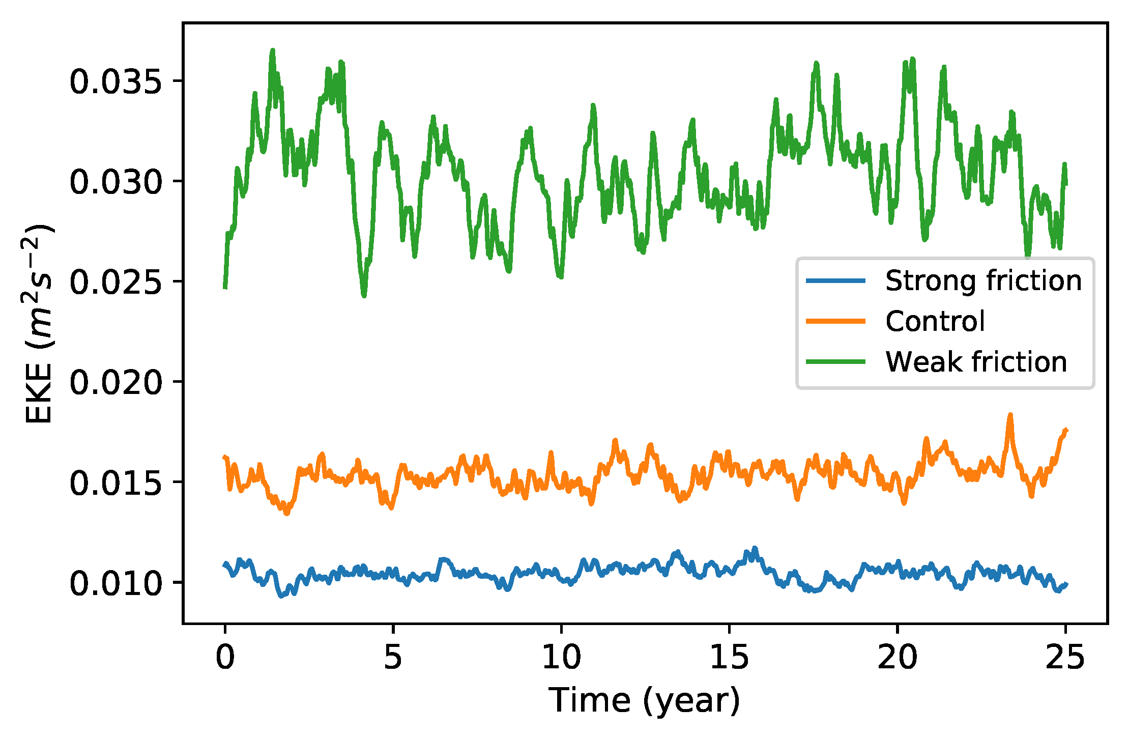
The model is run in a doubly periodic domain 1200 km on a side with a horizontal resolution of grid points. Each case was run for 60 years with time step of 10 or 5 min, and the last 50 years were sampled daily to calculate the diagnostics. Figure 1 gives the eddy kinetic energy (EKE) time series in the upper layer over 25 years for the three reference simulations; here “eddy” refers to a deviation from the time-independent, zonal-mean flow. The standard deviation of the EKE is 4–8% of its mean value, and all three experiments show episodes where the EKE grows or decays by 20–30%. This implies that relatively long time averages will be necessary to obtain robust statistics.
2.2. Lagrangian Particle Advection and Lagrangian Diffusivity
Once the flow is equilibrated, the upper layer is seeded with Lagrangian particles whose positions, , evolve according to:
where is the velocity. The particles are initialized on a rectangular grid with a uniform spacing of 1.2 km for a total of 1,048,576 particles. They are advected for 90 (for RCLV detection) or 360 (to estimate Taylor diffusivity) days with their positions, velocities, vorticities, and PV saved daily. The RCLV detection process was repeated for one hundred continuous and nonoverlapping intervals.
Particle trajectories are used to calculate the Lagrangian diffusivity. According to Taylor [44], for homogeneous and stationary turbulent flow, the Eulerian diffusivity is consistent with the single-particle Lagrangian diffusivity, which can be estimated as
where is the meridional position of a particle released at at time , and N is the total number of particles.
2.3. Identification of Coherent Eddies
We use the Lagrangian Averaged Vorticity Deviation (LAVD) technique of Haller et al. [32] to detect coherent eddies, which are defined as a nested family of fluid tubes which rotate collectively around a common core. The cores of coherent eddies are identified as the maxima of LAVD, defined as
where is the vorticity of the particle located at position at time , and is the domain-averaged vorticity (zero in the present case). The integrand is the vorticity deviation—the absolute difference of vorticity from its domain average—so, the LAVD field is the vorticity deviation averaged along the Lagrangian trajectories over the time interval . Closed contours of LAVD surrounding a maximum thus represent rings of particles rotating around the core of an eddy at the same average rate over the specified time interval. The outermost convex LAVD contour is defined as the material boundary of the eddy which is expected to trap all the fluid parcels inside during that time interval.
Figure 2a,c show example sets of LAVD contours around a local maximum where the LAVD field is plotted at the initial positions of particles at time . The outermost LAVD contour is determined by a threshold of a Coherency Index (CI). CI measures the variation of spatial compactness of particles initially inserted within an LAVD contour and is defined as
where is the variance of particle positions inside an LAVD contour at time t, is the position of the particle at time t, , indicates the average over all the particles inside the contour, and is the standard Euclidean distance. The Coherency Index compares the maximum of to , which is the variance of the same number of particles in a disk with radius of R. Since a disk is the most compact form of a particle cloud, any stretching or filamenting of the particle cloud will make CI negative. The definition of CI in this study is different from the one defined by Tarshish et al. [38], which measures the change of variance of particle positions at the final time relative to their initial variance. This metric tends to favor large, spatially extended initial particle clouds. In this study, the normalization factor does not depend on time or initial conditions and the particle spread is checked at each time step. A detailed description of the advantages of this CI will be discussed in a forthcoming paper.
Here, we choose the threshold for CI as . If the eddy remained elliptical, this value would correspond to an ellipse with an eccentricity of 94.9% (semi-major axis 3.2 times greater than the semi-minor axis). Figure 2b,d show the variation of CI on a nested set of LAVD contours for two example eddies. The value of CI typically drops rapidly below the threshold value at certain contour level, which indicates that the enclosed eddy is no longer fully coherent. Similar patterns are found in many examples, which suggests that this value is an approximate critical value below which the contour encloses incoherent particles. Sensitivity tests of the threshold of CI on the coherent eddy statistics are conducted by varying the threshold of CI to and (eccentricities of 92.4% and 96.3%, respectively) to detect the 30-day coherent eddies in different friction simulations (shown as the red and black stars in the following figures of eddy statistics). Increasing (decreasing) the magnitude of the CI threshold increases (decreases) the number of detected eddies by about 25% but does not significantly affect the statistics of coherent eddy properties (e.g., the eddy radius, zonal propagation velocity, and meridional PV flux).
In summary, the algorithm for detecting the coherent eddies within the LAVD field is the following:
- Identify all the LAVD maxima with a minimum separation of 20 pixels (minimum separation suggested by Tarshish et al. [38]).
- Search from each maximum in LAVD for the outermost LAVD contour satisfying CI using the bisection method with an initial contour level of 0.36 times the LAVD value of the maximum.
- Remove eddies containing fewer than 200 particles (approximately equivalent to an area of 274 ).
This algorithm is implemented by a Python package, floater modified from Abernathey [45].
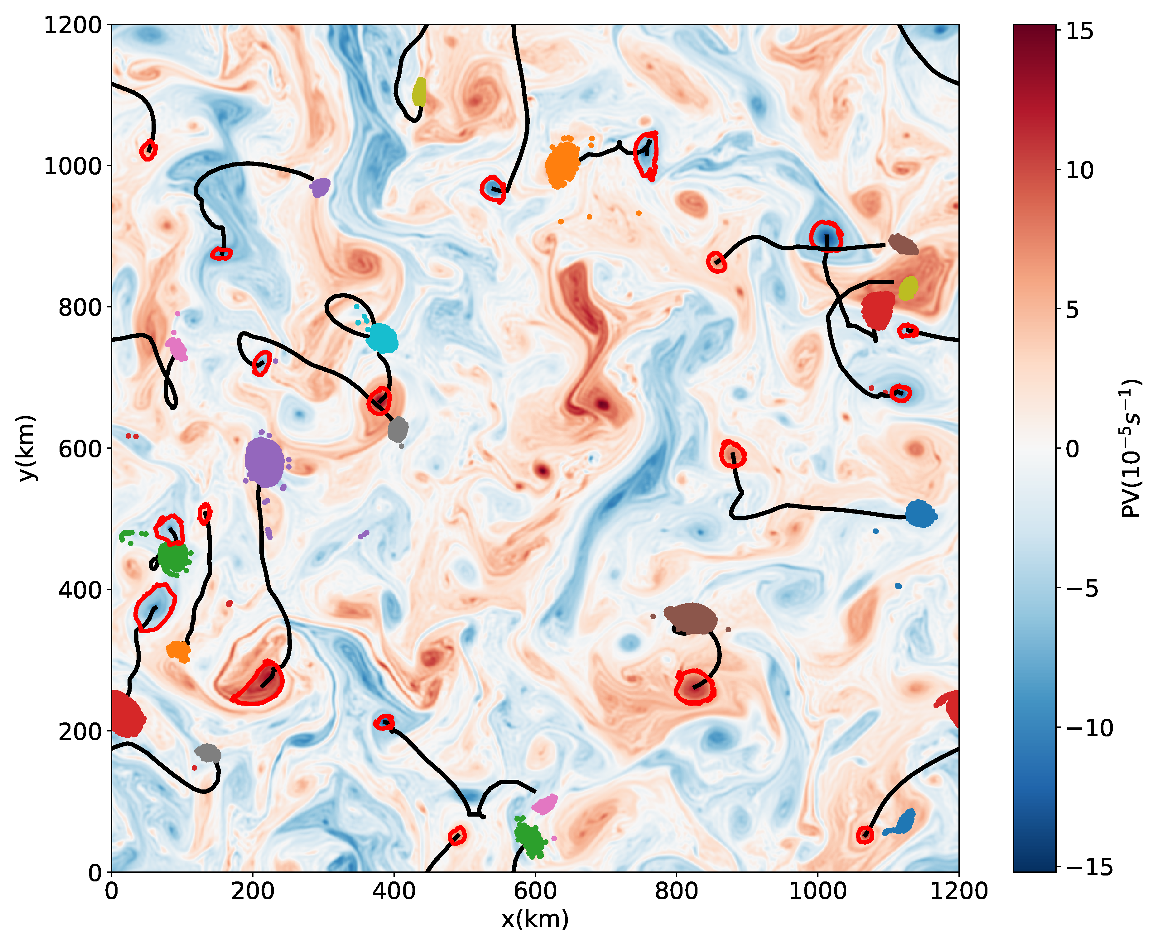
An example set of 30-day coherent eddies is shown in Figure 3, the particles inserted initially within the outer boundary of the eddies remain together in a compact shape after 30 days, with a few exceptions where eddies lose a small number of particles by the end of the 30-day period.
3. Eddy Statistics
3.1. Occurrence Frequency of Coherent Eddies
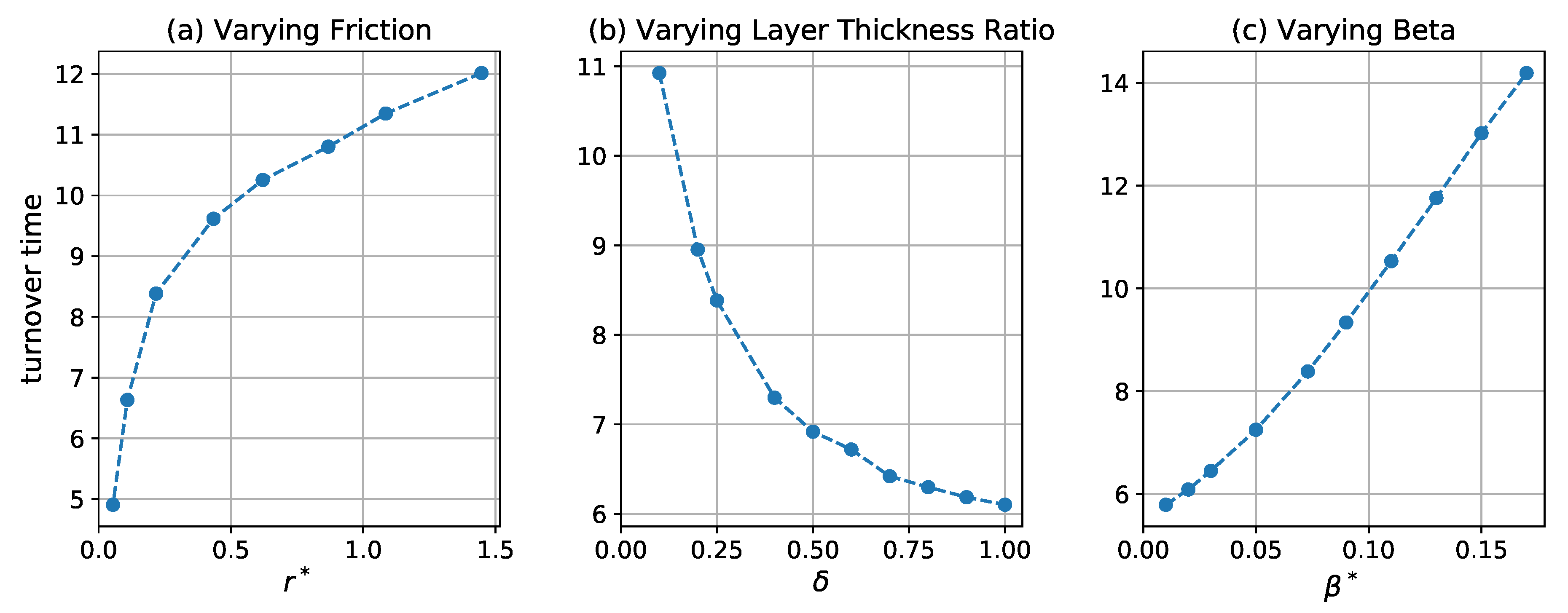
The method outlined in the previous section was used to detect 30-day, 60-day and 90-day coherent eddies in the first 30-, 60-, and 90-day periods of each of the 100 90-day intervals. The shortest interval is at least three times the eddy turnover time, estimated by , where Z is the spatial mean eddy enstrophy in the upper layer. This eddy turnover time is shown in Figure 4 as a function of nondimensional friction parameter, , layer thickness ratio, , and nondimensional beta, . It increases with increasing friction and beta parameters and decreases with increasing thickness ratio.
The number of coherent eddies in the 30-, 60-, and 90-day intervals are shown in Figure 5a–c. Shorter-lived eddies are systematically more prevalent than longer-lived eddies. Note that each 30-day period is included in the corresponding 60-day period, which is itself included in the corresponding 90-day period. Therefore, the 90-day eddies are subsets of the 60-day eddies, which are again subsets of the 30-day eddies. For the cases with varying and , the number of eddies in a given time interval tracks the eddy turnover time, and they become less numerous as the turnover time decreases. A simple interpretation of this observation is that eddies have a uniform probability of loosing coherence when time is measured in turnover times, so that the number of coherent eddies in a given time interval decreases as the number of turnover times in that interval increases. If the probability that an eddy loses coherence were indeed uniform, the number of eddies of a given age (measured in turnover times) should decrease exponentially. Fits of eddy number to exponential decay laws are shown in Figure 5d,e; the fits are significant () and the cases with fixed give approximately the same decay rate of per turnover time, implying that an eddy has a nearly 20% probability of losing coherence over each turnover time. The number distribution has some curvature when plotted on a log scale and the residual of power-law fit is slightly smaller than that of exponential fit in Figure 5e. A power-law decay means that the probability of eddy death is not uniform with age—in particular, older eddies are slightly less likely to loose coherence in a given time interval than younger eddies.
The prevalence and lifetimes of coherent eddies do not follow the eddy turnover time for the cases with varying . The turnover time increases monotonically as increases, but the number of coherent eddies decreases as increases until it reaches a minimum and then increases again (Figure 4c and Figure 5c). The minimum eddy number occurs at for 60- and 90-eddies and for 30-day eddies. However, the normalized eddy lifetime does increase monotonically as increases (Figure 5f); in particular, the exponential decay rate of the coherent eddies, , is well-approximated by (Figure 6). The non-monotonic behavior in Figure 5c is, therefore, due to the competition between increasing turnover time and decay rate as increases.
Why do coherent eddies decay more quickly as increases? The -effect causes isolated vortices to lose energy at a rate proportional to and the eddy’s angular momentum by radiating Rossby waves [46,47,48,49]. Since the turnover time is inversely proportional to angular momentum, larger values of lead to more rapid decay relative to the turnover time. The recoil caused by the radiation of Rossby waves additionally leads isolated vortices to propagate meridionally on the -plane, with cyclones and anticyclones drifting north and south, respectively, in the Northern Hemisphere [46,48,49,50]. While the coherent eddies considered in this study are not isolated, their decay rate is indeed proportional to , and we verify in Section 3.4.2 that they propagate meridionally in a manner analogous to isolated eddies. These results suggest that the basic physics governing the propagation and decay of isolated eddies on the -plane continues to operate in geophysical turbulence with many interacting eddies.
The different location of the minimum for 30-day eddies compared to 60- and 90-day eddies may be due to the fact that the turnover time is a substantial fraction of 30 days, especially for the larger values of . Since the eddies are only able to complete a few rotations within 30 days, there is little opportunity for them to lose coherence.
3.2. Eddy Radius Distribution
Eddy radius is estimated by , where A is the area enclosed by the outer boundary of the eddy (i.e., the red curves in Figure 3). The distribution of the eddy radii is given in Figure 7. The coherent eddies are generally small, with mean radii 10–40% larger than the deformation radius, . Arbic and Flierl [42] report eddy scales of roughly twice the deformation radius for parameter ranges similar to those considered here. The smaller values found here are due partially to differences in definition, as Arbic and Flierl [42] define “eddy scale” as the reciprocal of the first momentum of kinetic energy spectrum, while here it is the radius of a coherent core embedded in a larger eddy structure. An alternative eddy radial scale is the e-folding scale of its PV distribution, which is typically around 1.2 times the radius of the coherent core (cf. Figure 8).
Longer-lived coherent eddies have smaller coherent cores for all parameter values. This is because longer-lived coherent eddies are subsets of shorter-lived coherent eddies and particles near the outer edge are more likely to be lost as the eddy interacts with other eddies and the exterior straining flow. A given 90-day eddy begins life as a larger 30-day eddy and gradually loses particles, becoming a smaller 60-day eddy, and, finally, a still smaller 90-day eddy. Only the particles retained for the full 90 days are labeled as “belonging” the 90-day eddy, and these particles are closer to the eddy center than those retained for only 30 or 60 days.
The mean radius of the coherent core becomes slightly larger as increases, which is consistent with Arbic and Flierl [42], who show that the eddy length scale of weakly-damped eddies increases weakly as approaches order one. Evidently, larger eddies are able to host larger coherent cores. The radius of the coherent cores initially decreases as and increase from small values then stabilizes. The decrease with largely parallels the decrease in the turnover time and eddy number seen in Figure 4 and Figure 5. The upper layer becomes more energetic as the stratification becomes less surface-intensified [42], so eddy interactions are more frequent and involve stronger strain fields; both of these effects would tend to make it more difficult for the eddies to retain fluid parcels along their periphery. The initial decrease in radius with is likely related to the fact that the -effect can halt inverse energy cascade to large scales [43,51].
3.3. Radial Structure
The radial structure of the vorticity of isolated vortices in a two-dimensional viscous flow has been shown to have an analytical form
where and are vorticity anomaly and radial distance normalized by the amplitude at eddy center and radius of the corresponding eddies. The form given in (11) is a similarity solution for the viscous decay of initially compact eddies with zero net vorticity; it was derived by Taylor [52], observed in laboratory experiments [53], and has been adopted to describe the radial structure of pressure anomaly—instead of vorticity—for ocean mesoscale eddies observed in satellite and Argo observations [54].
We compare the radial structure of the coherent eddies to (11), using PV instead of vorticity because the PV is the QG analog of vorticity in two-dimensional flow. The PV and radial distance r are normalized by and , respectively, where , is the PV anomaly at the center of the eddy, and the scale parameter is the e-folding scale of the PV distribution of the eddy. The radial distribution of each eddy is obtained by azimuthally averaging in contiguous radial windows of length of 0.1 . The average normalized radial PV structure for all the eddies is shown in Figure 8. The radial PV structure has a negative lobe similar to the theoretical function (11) but is steeper near the eddy center, and the minimum is shifted away from the origin. The negative lobe indicating the opposite-sign PV rings around the eddies becomes smaller as the friction increases.
3.4. Eddy Propagation
3.4.1. Zonal Propagation
The mean zonal propagation velocity of the coherent eddies is estimated by their zonal displacements over their corresponding time interval. Studies have suggested that the eddy zonal phase speeds estimated from satellite observations can be predicted by the linear baroclinic Rossby wave theory [36,46]. In the long-wave limit, taking into account the Doppler shift by the mean flow [36,43], the baroclinic Rossby wave speed is estimated as
where is the depth-averaged mean flow. For the control simulation case, cm s−1 and cm s−1. Figure 9 shows the zonal propagation velocities of coherent eddies are systematically eastward and larger than except for the very weak friction and large thickness ratio cases. This may be due to the tendency of the eddies to concentrate in the faster upper layer when friction is stronger and stratification is more surface-intensified [43]. When decreases or increases, the eddy propagation velocity decreases or even turns westward, which is due to the larger contribution of the barotropic mode as bottom friction becomes weaker and stratification is less surface-intensified [43]. By varying the planetary vorticity gradient beta, the eddy propagation velocity is always eastward and decreases in the similar rate as the linear decrease of as beta increases.
3.4.2. Meridional Propagation
As discussed in Section 3.1, isolated vortices on the -plane radiate Rossby waves and the recoil contributes to their meridional propagation. The propagation direction is correlated with the sign of their PV anomaly, with cyclones (anticyclones) drifting northward (southward) in the Northern Hemisphere. The preference for cyclones and anticyclones to drift in opposite directions has been observed in a global investigation of ocean mesoscale eddies [17], which indicates that this is a universal phenomenon for ocean eddies. Indeed, McWilliams and Flierl [46] demonstrated that the secondary circulation induced by the leading and trailing streamfunction anomalies of an anticyclone acts to advect it southward. They showed that nonlinearity is essential for this self-advection process, and beta effect acts to induce the initial streamfunction dispersion. Similar mechanism is also discussed by Cushman-Roisin and Beckers [55] with clear schematics. A more fundamental interpretation is that a vortex has tendency to return to a rest latitude where the ambient PV matches that of the eddy [46,56]. Since the meridional drift reduces the eddy’s PV anomaly, this drift contributes to eddy decay and may lead to loss of coherence.
Interacting eddies are also randomly displaced meridionally due to their mutual interaction—indeed, only about 60% of the coherent eddies in a given sample propagate in the direction implied by their polarity. However, the -induced meridional drift becomes apparent when averaged over many eddies. Figure 10 shows the variation of mean eddy meridional propagation velocity with the three nondimensional parameters. The meridional speed of coherent eddies increases as decreases and increases (Figure 10a,b). This is because the flow becomes more barotropic for small and large and the meridional -drift primarily driven by coupling to barotropic Rossby waves [49]. As increases, the mean meridional speed initially increases to a maximum value at around and then decreases. The initial increase is driven by the increased momentum transport by radiated Rossby waves as increases. For sufficiently large values of , however, the inverse cascade preferentially transfers energy into zonal flows [51,57], which tends to suppress meridional propagation.
4. PV Transport by Coherent Eddies
4.1. Transport by Trapping
The Lagrangian trajectories of the coherent eddies can be used to estimate their PV transport. The total Lagrangian advective PV flux in the meridional direction is
where and are the velocity and PV anomalies for each Lagrangian particle, and the overbar is an ensemble average over all the Lagrangian particles during each 30-, 60-, or 90-day period.
The PV flux due to the coherent eddies is
where A is a masking function that is 1 for particles inside coherent eddies and 0 outside. is the fractional area occupied by coherent eddies, so is the mean flux per coherent particle due to coherent eddies—the total PV flux due to coherent eddies is obtained by multiplying (14) by . The PV flux per particle due to incoherent motions is
where is fraction of the domain outside of coherent eddies. Figure 11 shows the statistics of coherent PV flux, , calculated in each of the 30-, 60-, and 90-day periods and the corresponding time averaged incoherent PV flux, . The total incoherent flux, , is close to the total PV flux since the area occupied by coherent eddies is small. For all these cases, the coherent PV flux, , is systematically positive (upgradient), while the mean incoherent PV flux, , is always negative (downgradient). This means that the PV transport inside coherent eddies is systematically opposite to the transport in the background flow.
Both and increase as decreases and increases, which is consistent with the increase of eddy meridional propagation speed in these regimes (Figure 10a,b). The flow becomes more energetic and motive as bottom friction becomes weaker and stratification is less surface-intensified, which gives rise to larger PV anomalies and stronger advection of PV by both eddy and background flows. increases with to a maximum value first and then decreases as is larger, which is also related to the change of meridional propagation speed of coherent eddies with , while always decreases with , which is due to the suppression of meridional PV diffusion by stronger meridional PV gradient [57].
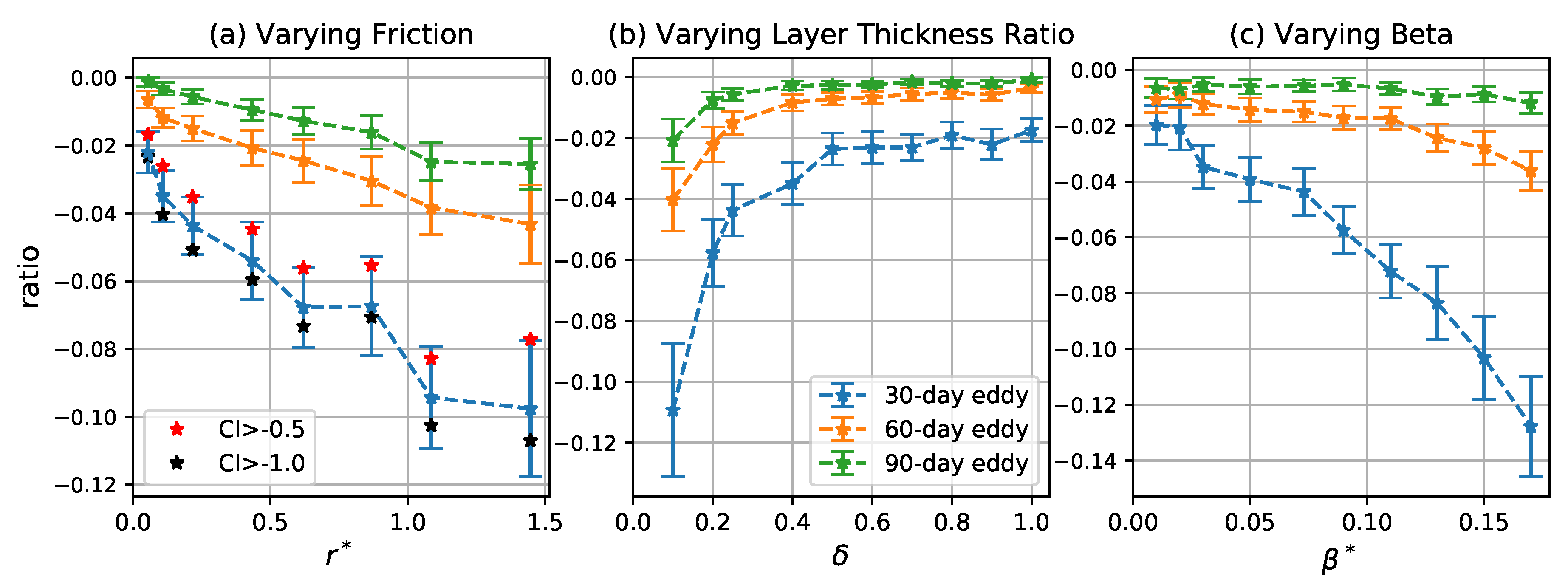
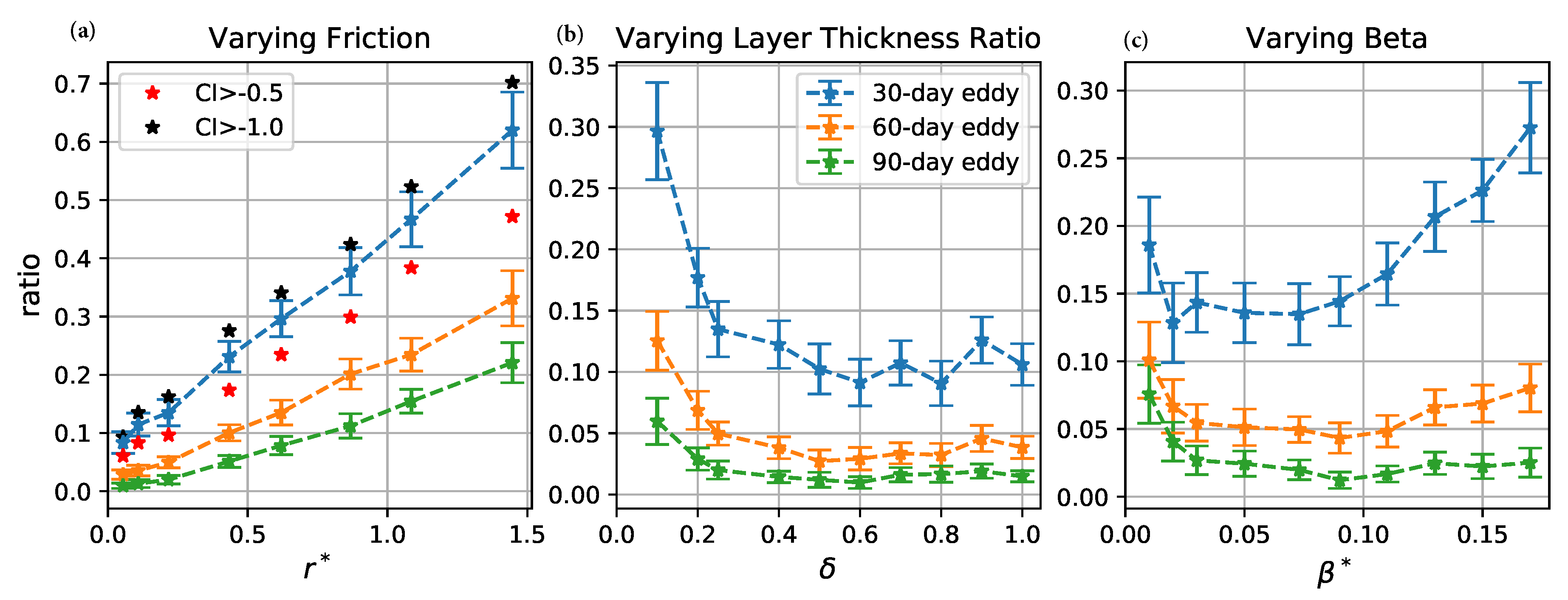
The total meridional PV flux by coherent eddies is , so the fraction of the total flux due to coherent eddies is . Figure 12 shows the mean of the ratio is systematically less than 15% in all the cases. Thus, the PV transport by coherent eddies is small compared to the total PV transport, but is systematically in the opposite direction. The fraction of the total flux due to coherent eddies increases as increases and decreases. Although decreases with increasing and decreasing , the background incoherent PV flux decreases in a even faster rate (Figure 11), and the fractional area occupied by coherent eddies, , increases due to the increase of number and radius of coherent eddies (Figure 5 and Figure 7), so (where ) increases in these cases. As increases, initially decreases due to the decrease of number and radius of coherent eddies, but it is compensated by the initial increase of and decrease of (Figure 11), so overall increases with .
The upgradient coherent PV flux is due to the systematically poleward translation of cyclones and equatorward translation of anticyclones (cf. Section 3). Since the total PV transport must be downgradient in statistical equilibrium, the downgradient incoherent PV transport over the whole domain must be much larger to compensate for the upgradient transport due to coherent eddies. This sets a dynamical constraint on the contribution of PV transport due to coherent eddies. However, were flows less zonally uniform, advection of enstrophy by mean flow might become important [58]. Holland and Rhines [59] showed that strong advection of enstrophy by gyres leads to both up- and downgradient PV fluxes. Thus, the upgradient PV transport by coherent eddies might be more significant in regions with strong nonuniform or nonzonal mean flows.
4.2. Transport by Stirring
The small contribution of PV transport inside coherent eddies does not necessarily mean that coherent eddies are not important in meridional PV transport. In addition to trapping fluid inside their cores, coherent eddies also induce the flow in the far field. Transport by these flows can also be thought of as “due to” the coherent eddies. Studies of two-dimensional turbulence have proposed a two-component fluid view [22,60] for modeling flow with coherent vortices immersed in background turbulence. The main idea for this view is to decompose the Eulerian flow into two dynamical components: one is generated by coherent vortices and the other is generated by the background vorticity field [24]. This allows us to estimate the transport by the flow induced by coherent eddies including the far field.
The flow induced by the coherent eddies is calculated using piecewise PV inversion (PPVI) [61,62,63]. PPVI has been widely used in diagnosing the effect of portions of the PV in geophysical systems, such as the effect of a PV anomaly at the tropopause on the cyclogenesis [64]. The PV inversion process is linear in QG, so the total flow is the sum of flows induced by all the portions of the PV. Specifically, the streamfunction for the total flow is decomposed as
where and are the flow generated by the coherent eddies and the background PV field, respectively. The former is calculated by the inversion of the PV field which is nonzero only in the upper layer inside coherent eddies. The incoherent flow, , is derived from the remaining PV field, including the lower layer. An example of the flow field is shown in Figure 13—the PV inside coherent eddies induce the flow throughout the whole domain.
The meridional PV flux due to is , where q is the total (coherent plus incoherent) PV field. The PV transport by the flow induced by coherent eddies is 10–60% of the total PV transport in all the cases (Figure 14). The change of with the three parameters has the similar trend as the change of number of coherent eddies (Figure 5). In addition, this transport is systematically downgradient, so the net PV transport due to both the stirring and trapping effect of coherent eddies is downgradient. Therefore, the meridional PV transport due to coherent eddies is primarily due to stirring rather than the drift of their cores, but these two components are actually correlated with each other. More than 80% of the induced PV transport is localized within three radii of the coherent cores; in this region, more than 50% of the EKE is induced by the PV inside the eddy cores.
5. Tracer Transport by Coherent Eddies
The PV distribution is highly correlated with the eddies—indeed, the eddies are PV extrema almost by definition. The role of coherent eddies in the transport of a “generic” passive tracer (i.e., a tracer whose initial distribution is independent of the distribution of the eddies) is also of interest. In this section, we focus on the three reference simulations for brevity.
The single-particle Lagrangian diffusivity is calculated by (8) in a 360-day period. The time series of the Lagrangian diffusivity in the three reference cases are shown in Figure 15 and compared to the Eulerian meridional PV diffusivity
where an overbar indicates an area and time average. The Eulerian diffusivity becomes larger as the friction weakens. The Lagrangian diffusivity of all the three simulations increases to a maximum within the first 10 days, and then decays and asymptotes to a constant value which is close to the domain-mean Eulerian diffusivity.
We can use a small modification of the Taylor diffusivity (8) to calculate the coherent diffusivity; that is, the diffusivity due to coherent eddies. The modified diffusivity is
where is a masking function which is unity for particles inside coherent eddies and zero otherwise.
The coherent diffusivity increases to a maximum within the first 1–2 days, then drops to a local minimum near the 5th day, and then increases again (Figure 16). The period of this diffusivity oscillation is on the same order of the eddy turnover time, so may be due to the swirling motion of the eddies. After this oscillation, the coherent diffusivity converges to the Eulerian diffusivity much faster than the Lagrangian diffusivity averaged over all the particles. However, this does not mean the coherent diffusivity represents the total Lagrangian diffusivity. The contribution of coherent eddies to the total diffusivity is , which is the same as the ‘coherent diffusivity’ defined in Abernathey and Haller [34]. Indeed, the fraction of Lagrangian diffusivity due to coherent eddies is less than 2% for the three friction cases shown in Figure 16. The estimate for 30-day eddies is slightly larger than the estimate by Abernathey and Haller [34] but is still not a significant contribution to the total diffusivity. The smallness of the coherent diffusivity is due to the small fractional area, , occupied by coherent eddies.
The coherent diffusivity is mostly positive, which is inconsistent with the upgradient coherent PV flux discussed in Section 4. This implies that the PV transport by the coherent cores is not a diffusion process and is not captured merely by the dispersion of Lagrangian particles in the cores. Taylor’s [44] derivation assumes that the initial tracer gradient is uniform and that the particle motion is independent of the tracer distribution. This is clearly not the case for PV transport by coherent eddies since the eddies themselves are the PV extrema, and their motion depends on the sign of their PV. Therefore, Taylor’s theory is not applicable to PV transport by coherent eddies since its assumptions are violated.
6. Summary and Conclusions
This study uses the objective Lagrangian coherent eddy detection method of Haller et al. [32] to identify the surface-layer coherent eddies in two-layer quasigeostrophic turbulence. Materially coherent eddies are detected for a wide range of parameters, with stronger bottom friction and stronger surface-intensified stratification associated with a greater prevalence of coherent eddies. These flow regimes are generally less energetic and more baroclinic. The number of coherent eddies is minimum when the shear-induced PV gradient is 10–20 times the background PV gradient, and as the background PV gradient is larger or smaller than that pivot value, the number of coherent eddies increases. The coherent eddies take the form of a small (near the deformation radius) materially coherent core embedded in a larger area of PV anomaly characterized by incoherent particle motion. The mean radius of coherent eddy cores increases with stronger bottom friction, while it decreases and approaches to a constant value as stratification is less surface-intensified and background PV gradient decreases.
The cyclonic and anticyclonic eddies have distinct preferences for meridional propagation. Cyclonic eddies systematically propagate poleward and anticyclonic eddies propagate equatorward, which gives rise to upgradient PV transport. This upgradient PV transport is the opposite of the general PV transport by the background flow and is not captured by the Lagrangian diffusivity of Taylor [44]. This implicates the PV transport by coherent eddies is distinct from the diffusion process, indicating a special dynamical role played by them. The meridional propagation speed of coherent eddies increases with weaker bottom friction and less surface-intensified stratification, which gives rise to stronger PV flux per coherent particle. However, the contribution of coherent eddies to the total meridional PV transport increases as the bottom friction is stronger and stratification is more surface-intensified, where the coherent eddies are more numerous but propagate more slowly in the meridional direction. That means the coherent eddy transport tends to be more important in a slower and less energetic flow regime, where the background filaments and strains are suppressed. As the background PV gradient, , increases, the mean meridional propagation speed of coherent eddies initially increases to a maximum value due to enhanced Rossby wave radiation but then decreases as further increases. Combining with the change of number of coherent eddies with , the overall contribution of coherent eddies to total PV transport increases as increases.
The PV transport due to the drift of coherent eddy cores is generally small (less than 15%) compared to the total PV transport, but these coherent cores can induce the flow in the far field which gives rise to significant downgradient PV transport in the periphery of the eddy cores. The former component of the transport is due to trapping, while the latter is due to stirring. This study shows that the stirring transport by coherent eddies is more likely to be parameterized as a diffusion process, while the trapping transport—although itself small—might determine the evolution of eddies themselves. How the trapping and stirring transport correlate with each other and how they are correlated with the formation and decay of coherent eddies needs further study. On the other hand, the two-layer QG model in this study might not fully consider the three-dimensionality of the eddies, which has been shown to lead to a stronger filamentary background than the two-dimensional case [65]. Looking at the contribution of transport by coherent eddies in the two-component fluid view in a fully three-dimensional QG model is an another direction of the future work.
The meridional propagation tendency of coherent eddies relies on the -effect, and PV is itself an active tracer, which makes the PV transport special. It would also be interesting to investigate the role of coherent eddies in the transport of tracers, like heat and biochemical constituents, which have been shown to correlate with the signs of PV of mesoscale eddies in the ocean. Thompson and Young [25] investigated the eddy heat flux in a two-mode, f-plane QG model and proposed that the downgradient heat flux is due to the systematic propagation of hot anticyclones poleward and cold cyclones equatorward, which is opposite to our cases. However, Dong et al. [27] showed that the heat transport by mesoscale eddies in the ocean is significantly upgradient near the tropics. It would be worthwhile to investigate this process in the -plane QG model.
The flows considered in this study are zonal background mean flows with statistically homogeneous geostrophic turbulence, while the transport and mixing in ocean gyres might be nonzonal, anisotropic, and inhomogeneous [23]. Previous studies on oceanic circulations have shown that statistics and tracer transport by eddies can differ from homogeneous case in many ways, with more energetic eddies arising in nonzonal mean flows [40], subdiffusive single-particle dispersion due to coherent structures [23], mixing nonlocality within jets [66] and the transport barriers in eastward jets. Whether the trapping or stirring transport of coherent eddies is significant in such systems and how coherent eddies interact with the zonal jets or meridional western boundary currents would be interesting to explore. On the other hand, all the flow regimes in this study are forced by the eastward background flow vertical shear, while study by Arbic and Flierl [40] suggested that more vortices might form in the westward zonal mean shear case. Berloff et al. [67] showed that the vortices would tend to propagate down the upper-layer meridional PV gradient (i.e., southward) in the westward zonal mean shear case. Whether the statistics and PV transport by coherent eddies will be significantly changed in that flow regime is interesting to explore in the future. Better understanding of the universal transport properties of coherent eddies will improve our ability to diagnose the turbulent flow structures and parameterize the eddy fluxes in coarse-resolution climate models.
Author Contributions
Conceptualization, R.A., C.L.P.W. and W.Z.; methodology, R.A.; software, R.A., W.Z. and C.L.P.W.; validation, W.Z., C.L.P.W. and R.A.; formal analysis, W.Z. and C.L.P.W.; investigation, W.Z. and C.L.P.W.; resources, RA. and C.L.P.W.; data curation, W.Z.; writing—original draft preparation, W.Z.; writing—review and editing, C.L.P.W. and R.A.; visualization, W.Z. and C.L.P.W.; supervision, C.L.P.W. and R.A.; project administration, C.L.P.W. All authors have read and agreed to the published version of the manuscript.
Funding
This research received no external funding.
Acknowledgments
We thank Stony Brook Research Computing and Cyber Infrastructure and the Institute for Advanced Computational Science at Stony Brook University for access to the high-performance SeaWulf computing system, which is supported by the NSF. We would like to thank two anonymous reviewers for their helpful comments, which significantly improved this study. We also thank John Marshall for suggesting the piecewise PV inversion method.
Conflicts of Interest
The authors declare no conflict of interest. The funders had no role in the design of the study; in the collection, analyses, or interpretation of data; in the writing of the manuscript, or in the decision to publish the results.
Abbreviations
The following abbreviations are used in this manuscript:
| LAVD | Lagrangian-averaged vorticity deviation |
| PV | potential vorticity |
| RCLV | rotationally-coherent Lagrangian vortex |
| QG | quasigeostrophic |
| EKE | eddy kinetic energy |
| CI | coherency Index |
| PPVI | piecewise PV inversion |
| NSF | National Science Foundation |
References
- Hallberg, R.; Gnanadesikan, A. The role of eddies in determining the structure and response of the wind-driven Southern Hemisphere overturning: Results from the Modeling Eddies in the Southern Ocean (MESO) project. J. Phys. Oceanogr. 2006, 36, 2232–2252. [Google Scholar] [CrossRef] [Green Version]
- Marshall, J.; Radko, T. Residual-mean solutions for the Antarctic Circumpolar Current and its associated overturning circulation. J. Phys. Oceanogr. 2003, 33, 2341–2354. [Google Scholar] [CrossRef]
- Marshall, J.; Radko, T. A model of the upper branch of the meridional overturning of the Southern Ocean. Prog. Oceanogr. 2006, 70, 331–345. [Google Scholar] [CrossRef]
- Wolfe, C.L.; Cessi, P. Overturning circulation in an eddy-resolving model: The effect of the pole-to-pole temperature gradient. J. Phys. Oceanogr. 2009, 39, 125–142. [Google Scholar] [CrossRef] [Green Version]
- Wolfe, C.L.; Cessi, P. What sets the strength of the middepth stratification and overturning circulation in eddying ocean models? J. Phys. Oceanogr. 2010, 40, 1520–1538. [Google Scholar] [CrossRef]
- Griffiths, R.; Pearce, A. Satellite images of an unstable warm eddy derived from the Leeuwin Current. Deep Sea Res. Part A. Oceanogr. Res. Pap. 1985, 32, 1371–1380. [Google Scholar] [CrossRef]
- Fang, F.; Morrow, R. Evolution, movement and decay of warm-core Leeuwin Current eddies. Deep Sea Res. Part II Top. Stud. Oceanogr. 2003, 50, 2245–2261. [Google Scholar] [CrossRef]
- Kurian, J.; Colas, F.; Capet, X.; McWilliams, J.C.; Chelton, D.B. Eddy properties in the California Current System. J. Geophys. Res. Ocean. 2011, 116, C08027. [Google Scholar] [CrossRef]
- Cessi, P.; Wolfe, C.L. Eddy-driven buoyancy gradients on eastern boundaries and their role in the thermocline. J. Phys. Oceanogr. 2009, 39, 1595–1614. [Google Scholar] [CrossRef]
- Colas, F.; Capet, X.; McWilliams, J.C.; Li, Z. Mesoscale eddy buoyancy flux and eddy-induced circulation in Eastern Boundary Currents. J. Phys. Oceanogr. 2013, 43, 1073–1095. [Google Scholar] [CrossRef]
- Pelland, N.A.; Eriksen, C.C.; Lee, C.M. Subthermocline eddies over the Washington continental slope as observed by Seagliders, 2003–09. J. Phys. Oceanogr. 2013, 43, 2025–2053. [Google Scholar] [CrossRef]
- Bire, S.; Wolfe, C.L. The role of eddies in buoyancy-driven eastern boundary currents. J. Phys. Oceanogr. 2018, 48, 2829–2850. [Google Scholar] [CrossRef]
- Steinberg, J.M.; Pelland, N.A.; Eriksen, C.C. Observed evolution of a California Undercurrent eddy. J. Phys. Oceanogr. 2019, 49, 649–674. [Google Scholar] [CrossRef]
- McGillicuddy, D., Jr.; Anderson, L.; Doney, S.; Maltrud, M. Eddy-driven sources and sinks of nutrients in the upper ocean: Results from a 0.1∘ resolution model of the North Atlantic. Glob. Biogeochem. Cycles 2003, 17, 1035. [Google Scholar] [CrossRef]
- Siegenthaler, U. Uptake of excess CO2 by an outcrop-diffusion model of the ocean. J. Geophys. Res. Ocean. 1983, 88, 3599–3608. [Google Scholar] [CrossRef]
- Gnanadesikan, A.; Pradal, M.A.; Abernathey, R. Isopycnal mixing by mesoscale eddies significantly impacts oceanic anthropogenic carbon uptake. Geophys. Res. Lett. 2015, 42, 4249–4255. [Google Scholar] [CrossRef]
- Chelton, D.B.; Schlax, M.G.; Samelson, R.M. Global observations of nonlinear mesoscale eddies. Prog. Oceanogr. 2011, 91, 167–216. [Google Scholar] [CrossRef]
- Zhang, Z.; Wang, W.; Qiu, B. Oceanic mass transport by mesoscale eddies. Science 2014, 345, 322–324. [Google Scholar] [CrossRef]
- Zhang, Z.; Zhang, Y.; Wang, W. Three-compartment structure of subsurface-intensified mesoscale eddies in the ocean. J. Geophys. Res. Ocean. 2017, 122, 1653–1664. [Google Scholar] [CrossRef]
- McWilliams, J.C. The emergence of isolated coherent vortices in turbulent flow. J. Fluid Mech. 1984, 146, 21–43. [Google Scholar] [CrossRef] [Green Version]
- Provenzale, A. Transport by coherent barotropic vortices. Annu. Rev. Fluid Mech. 1999, 31, 55–93. [Google Scholar] [CrossRef] [Green Version]
- Bracco, A.; LaCasce, J.; Pasquero, C.; Provenzale, A. The velocity distribution of barotropic turbulence. Phys. Fluids 2000, 12, 2478–2488. [Google Scholar] [CrossRef]
- Berloff, P.S.; McWilliams, J.C.; Bracco, A. Material transport in oceanic gyres. Part I: Phenomenology. J. Phys. Oceanogr. 2002, 32, 764–796. [Google Scholar] [CrossRef]
- Pasquero, C.; Provenzale, A.; Babiano, A. Parameterization of dispersion in two-dimensional turbulence. J. Fluid Mech. 2001, 439, 279–303. [Google Scholar] [CrossRef]
- Thompson, A.F.; Young, W.R. Scaling baroclinic eddy fluxes: Vortices and energy balance. J. Phys. Oceanogr. 2006, 36, 720–738. [Google Scholar] [CrossRef]
- Berloff, P.S.; McWilliams, J.C. Material transport in oceanic gyres. Part II: Hierarchy of stochastic models. J. Phys. Oceanogr. 2002, 32, 797–830. [Google Scholar] [CrossRef] [Green Version]
- Dong, C.; McWilliams, J.C.; Liu, Y.; Chen, D. Global heat and salt transports by eddy movement. Nat. Commun. 2014, 5, 3294. [Google Scholar] [CrossRef] [Green Version]
- Haller, G. An objective definition of a vortex. J. Fluid Mech. 2005, 525, 1–26. [Google Scholar] [CrossRef] [Green Version]
- Beron-Vera, F.J.; Wang, Y.; Olascoaga, M.J.; Goni, G.J.; Haller, G. Objective detection of oceanic eddies and the Agulhas leakage. J. Phys. Oceanogr. 2013, 43, 1426–1438. [Google Scholar] [CrossRef]
- Haller, G.; Beron-Vera, F.J. Coherent Lagrangian vortices: The black holes of turbulence. J. Fluid Mech. 2013, 731, R4. [Google Scholar] [CrossRef] [Green Version]
- Wang, Y.; Olascoaga, M.J.; Beron-Vera, F.J. Coherent water transport across the South Atlantic. Geophys. Res. Lett. 2015, 42, 4072–4079. [Google Scholar] [CrossRef] [Green Version]
- Haller, G.; Hadjighasem, A.; Farazmand, M.; Huhn, F. Defining coherent vortices objectively from the vorticity. J. Fluid Mech. 2016, 795, 136–173. [Google Scholar] [CrossRef] [Green Version]
- Hadjighasem, A.; Farazmand, M.; Blazevski, D.; Froyland, G.; Haller, G. A critical comparison of Lagrangian methods for coherent structure detection. Chaos Interdiscip. J. Nonlinear Sci. 2017, 27, 053104. [Google Scholar] [CrossRef] [PubMed]
- Abernathey, R.; Haller, G. Transport by Lagrangian vortices in the eastern Pacific. J. Phys. Oceanogr. 2018, 48, 667–685. [Google Scholar] [CrossRef] [Green Version]
- Abernathey, R.P.; Marshall, J. Global surface eddy diffusivities derived from satellite altimetry. J. Geophys. Res. Oceans 2013, 118, 901–916. [Google Scholar] [CrossRef]
- Klocker, A.; Abernathey, R. Global patterns of mesoscale eddy properties and diffusivities. J. Phys. Oceanogr. 2014, 44, 1030–1046. [Google Scholar] [CrossRef]
- Wang, Y.; Beron-Vera, F.J.; Olascoaga, M.J. The life cycle of a coherent Lagrangian Agulhas ring. J. Geophys. Res. Oceans 2016, 121, 3944–3954. [Google Scholar] [CrossRef] [Green Version]
- Tarshish, N.; Abernathey, R.; Zhang, C.; Dufour, C.O.; Frenger, I.; Griffies, S.M. Identifying Lagrangian coherent vortices in a mesoscale ocean model. Ocean Model. 2018, 130, 15–28. [Google Scholar] [CrossRef]
- Spall, M.A. Generation of strong mesoscale eddies by weak ocean gyres. J. Mar. Res. 2000, 58, 97–116. [Google Scholar] [CrossRef] [Green Version]
- Arbic, B.K.; Flierl, G.R. Effects of mean flow direction on energy, isotropy, and coherence of baroclinically unstable beta-plane geostrophic turbulence. J. Phys. Oceanogr. 2004, 34, 77–93. [Google Scholar] [CrossRef] [Green Version]
- Abernathey, R.; Rocha, C.B.; Poulin, F.J.; Jansen, M.; Penn, J. pyqg: v0.2.0. 2016. Available online: https://zenodo.org/record/50569#.Xfwj6Px5vIU (accessed on 14 March 2019).
- Arbic, B.K.; Flierl, G.R. Baroclinically unstable geostrophic turbulence in the limits of strong and weak bottom Ekman friction: Application to midocean eddies. J. Phys. Oceanogr. 2004, 34, 2257–2273. [Google Scholar] [CrossRef] [Green Version]
- Wang, L.; Jansen, M.; Abernathey, R. Eddy phase speeds in a two-layer model of quasigeostrophic baroclinic turbulence with applications to ocean observations. J. Phys. Oceanogr. 2016, 46, 1963–1985. [Google Scholar] [CrossRef]
- Taylor, G.I. Diffusion by continuous movements. Proc. Lond. Math. Soc. 1922, 2, 196–212. [Google Scholar] [CrossRef]
- Abernathey, R. Floater. 2018. Available online: https://github.com/rabernat/floater (accessed on 1 April 2019).
- McWilliams, J.C.; Flierl, G.R. On the evolution of isolated, nonlinear vortices. J. Phys. Oceanogr. 1979, 9, 1155–1182. [Google Scholar] [CrossRef]
- Flierl, G.R. Rossby Wave Radiation from a Strongly Nonlinear Warm Eddy. J. Phys. Oceanogr. 1984, 14, 47–58. [Google Scholar] [CrossRef]
- Sutyrin, G.G.; Hesthaven, J.S.; Lynov, J.P.; Rasmussen, J.J. Dynamical properties of vortical structures on the beta-plane. J. Fluid Mech. 1994, 268, 103–131. [Google Scholar] [CrossRef]
- Korataev, G.K. Radiating Vorticies in Geophysical Fluid Dynamics. Surv. Geophys. 1997, 18, 567–619. [Google Scholar] [CrossRef]
- Early, J.J.; Samelson, R.; Chelton, D.B. The evolution and propagation of quasigeostrophic ocean eddies. J. Phys. Oceanogr. 2011, 41, 1535–1555. [Google Scholar] [CrossRef]
- Rhines, P.B. Waves and turbulence on a beta-plane. J. Fluid Mech. 1975, 69, 417–443. [Google Scholar] [CrossRef] [Green Version]
- Taylor, G. On the dissipation of eddies. In Meteorology, Oceanography and Turbulent Flow; Cambridge University Press: Cambridge, UK, 1918; pp. 96–101. [Google Scholar]
- Trieling, R.; Van Heijst, G. Decay of monopolar vortices in a stratified fluid. Fluid Dyn. Res. 1998, 23, 27. [Google Scholar] [CrossRef]
- Zhang, Z.; Zhang, Y.; Wang, W.; Huang, R. Universal structure of mesoscale eddies in the ocean. Geophys. Res. Lett. 2013, 40, 3677–3681. [Google Scholar] [CrossRef] [Green Version]
- Cushman-Roisin, B.; Beckers, J.M. Introduction to Geophysical Fluid Dynamics: Physical and Numerical Aspects; Academic Press: Waltham, MA, USA, 2011; Volume 101. [Google Scholar]
- Rossby, C.G. On a mechanism for the release of potential energy in the atmosphere. J. Meteorol. 1949, 6, 164–180. [Google Scholar] [CrossRef] [Green Version]
- Thompson, A.F.; Young, W.R. Two-layer baroclinic eddy heat fluxes: Zonal flows and energy balance. J. Atmos. Sci. 2007, 64, 3214–3231. [Google Scholar] [CrossRef] [Green Version]
- Marshall, J. Eddy-mean-flow interaction in a barotropic ocean model. Q. J. R. Meteorol. Soc. 1984, 110, 573–590. [Google Scholar] [CrossRef]
- Holland, W.R.; Rhines, P.B. An example of eddy-induced ocean circulation. J. Phys. Oceanogr. 1980, 10, 1010–1031. [Google Scholar] [CrossRef] [Green Version]
- Provenzale, A.; Babiano, A.; Bracco, A.; Pasquero, C.; Weiss, J. Coherent vortices and tracer transport. In Transport and Mixing in Geophysical Flows; Springer: Berlin/Heidelberg, Germany, 2008; pp. 101–118. [Google Scholar]
- Hoskins, B.J.; McIntyre, M.E.; Robertson, A.W. On the use and significance of isentropic potential vorticity maps. Q. J. R. Meteorol. Soc. 1985, 111, 877–946. [Google Scholar] [CrossRef]
- Davis, C.A. Piecewise potential vorticity inversion. J. Atmos. Sci. 1992, 49, 1397–1411. [Google Scholar] [CrossRef] [Green Version]
- Egger, J. Piecewise potential vorticity inversion: Elementary tests. J. Atmos. Sci. 2008, 65, 2015–2024. [Google Scholar] [CrossRef]
- Eliassen, A.; Kleinschmidt, E. Dynamic meteorology. In Geophysik II/Geophysics II; Springer: Berlin/Heidelberg, Germany, 1957; pp. 1–154. [Google Scholar]
- Petersen, M.R.; Julien, K.; Weiss, J.B. Vortex cores, strain cells, and filaments in quasigeostrophic turbulence. Phys. Fluids 2006, 18, 026601. [Google Scholar] [CrossRef]
- Chen, R.; Waterman, S. Mixing Nonlocality and Mixing Anisotropy in an Idealized Western Boundary Current Jet. J. Phys. Oceanogr. 2017, 47, 3015–3036. [Google Scholar] [CrossRef]
- Berloff, P.; Karabasov, S.; Farrar, J.T.; Kamenkovich, I. On latency of multiple zonal jets in the oceans. J. Fluid Mech. 2011, 686, 534–567. [Google Scholar] [CrossRef] [Green Version]
Figure 1.
Time series of upper layer eddy kinetic energy (EKE) of the three simulations. Blue, orange, and green curves indicate the weak friction, control, and strong friction cases, respectively.
Figure 1.
Time series of upper layer eddy kinetic energy (EKE) of the three simulations. Blue, orange, and green curves indicate the weak friction, control, and strong friction cases, respectively.

Figure 2.
(a,c): Lagrangian averaged vorticity deviation (LAVD) fields at the initial particle positions for two example eddies (shading). Contours give values relative to the LAVD maximum at the eddy center with the outer boundary obtained from the threshold Coherency Index (CI) indicated by a thick blue contour. (b,d): Radial distribution of the CI for the eddies shown in (a,c), respectively, as a function of contour. Dashed red lines indicate the threshold value for the CI.

Figure 3.
An example set of 30-day eddies from the weak friction case. The background field is the potential vorticity (PV) anomaly at the initial time, red curves give the boundaries of the coherent eddies at the initial time, black lines are the trajectories of eddy centers, and colored dots are the positions after 30 days of particles initially inside the eddies.

Figure 4.
Eddy turnover time in days as a function of the (a) friction parameter, , (b) layer thickness ratio, , and (c) beta parameter, .
Figure 4.
Eddy turnover time in days as a function of the (a) friction parameter, , (b) layer thickness ratio, , and (c) beta parameter, .

Figure 5.
Number of coherent eddies in each time interval as a function of (a) , (b) , and (c) . Blue, orange, and green curves correspond to the mean of the number of 30-, 60-, and 90-day eddies, respectively. Error bars give two times the standard error of the mean over 100 time intervals. Red and black stars in the left panel indicate the mean for 30-day eddies detected by varying the CI threshold to and , respectively. Average number of coherent eddies with lifetimes normalized by the eddy turnover time in each case for experiments varying (d) , (e) , and (f) . In (d) and (e), the black dashed line is an exponential fit , and the green dash-dot line is a power law fit , where N is the number of coherent eddies, and is the normalized lifetime. In (f), different colored dots indicate the simulations with different .

Figure 6.
Coherent eddy decay rate, , in units of inverse turnover time as a function of (blue). The orange line gives . The decay rate is obtained from exponential fits to the number of 30-, 60-, and 90-day eddies for each value of .
Figure 6.
Coherent eddy decay rate, , in units of inverse turnover time as a function of (blue). The orange line gives . The decay rate is obtained from exponential fits to the number of 30-, 60-, and 90-day eddies for each value of .

Figure 7.
Radius of coherent eddies as a function of (a) , (b) , and (c) . Blue, orange, and green curves correspond to the mean of the radius for 30-, 60-, and 90-day eddies, respectively. Error bars give two times the standard error of the mean. Red and black stars in the left panel indicate the mean for 30-day eddies detected by varying the CI threshold to and , respectively.

Figure 8.
Mean radial structure of PV in coherent eddies. Panels from top to bottom are from the strong, control and weak friction cases. The orange solid curve is the PV normalized by its maximum value in the eddy center and averaged over all the coherent eddies. The blue shading spans the 20th–80th percentiles of the normalized PV at each radial distance normalized by the e-folding scale of the PV distribution. The red dashed line is the theoretical radial structure given by (11) and is normalized by its own e-folding scale.

Figure 9.
Zonal propagation velocity of coherent eddies as a function of (a) , (b) , and (c) . Blue, orange, and green curves correspond to the mean of the zonal propagation velocity for 30-, 60-, and 90-day eddies, respectively. Error bars give two times the standard error of the mean. Red and black stars in the left panel indicate the mean for 30-day eddies detected by varying the CI threshold to and , respectively. The dashed cyan, black and red lines give the upper layer mean flow , depth-averaged mean flow , and baroclinic Rossby wave speed , respectively.

Figure 10.
Meridional propagation velocity of coherent eddies as a function of (a) , (b) , and (c) . Blue, orange, and green curves with correspond to the mean of the meridional propagation velocity for 30-, 60-, and 90-day eddies, respectively, and dashed curves with triangles and solid curves with circles indicate cyclonic and anticyclonic eddies, respectively. Error bars give two times the standard error of the mean. Red and black stars in the left panel indicate the mean for 30-day eddies detected by varying the CI threshold to and , respectively.

Figure 11.
Net meridional PV flux (per coherent particle) due to coherent eddies as a function of (a) , (b) , and (c) . Blue, orange, and green curves correspond to the mean of the net PV flux for 30-, 60-, and 90-day eddies, respectively. Error bars give two times the standard error of the mean over 100 time intervals. The dash-dot red, purple, and grey lines indicate the averaged incoherent meridional PV flux over the 100 30-, 60-, and 90-day intervals, respectively. Red and black stars in the left panel indicate the mean PV flux for 30-day eddies detected by varying the CI threshold to and , respectively.

Figure 12.
Ratio of meridional PV transport due to trapping of coherent eddies to total PV transport as a function of (a) , (b) , and (c) . Blue, orange, and green curves correspond to the mean of the ratio for 30-, 60-, and 90-day eddies, respectively. Error bars give two times the standard error of the mean over 100 time intervals. Red and black stars in the left panel indicate the mean for 30-day eddies detected by varying the CI threshold to and , respectively.

Figure 13.
An example of flow field induced by coherent eddies.

Figure 14.
Ratio of meridional PV transport by the flow induced by coherent eddies to total PV transport as a function of (a) , (b) , and (c) . Blue, orange, and green curves correspond to the mean of the ratio for 30-, 60-, and 90-day eddies, respectively. Error bars give two times the standard error of the mean over 100 time intervals. Red and black stars in the left panel indicate the mean for 30-day eddies detected by varying the CI threshold to and , respectively.

Figure 15.
Upper level Lagrangian diffusivity calculated by (8) (red curve) with shaded error bars of 2 times standard error, and Eulerian diffusivity (green dashed curve).
Figure 15.
Upper level Lagrangian diffusivity calculated by (8) (red curve) with shaded error bars of 2 times standard error, and Eulerian diffusivity (green dashed curve).

Figure 16.
Time series of coherent diffusivity (per coherent particle) in three simulations. Blue, orange, and green lines are 30-, 60-, and 90-day coherent diffusivities, respectively. Error bars give two times the standard error. Black lines indicate the Lagrangian diffusivity averaged over all the particles in the same time period. Red dashed line indicates the Eulerian diffusivity.

© 2019 by the authors. Licensee MDPI, Basel, Switzerland. This article is an open access article distributed under the terms and conditions of the Creative Commons Attribution (CC BY) license (http://creativecommons.org/licenses/by/4.0/).
Share and Cite
MDPI and ACS Style
Zhang, W.; Wolfe, C.L.P.; Abernathey, R. Role of Surface-Layer Coherent Eddies in Potential Vorticity Transport in Quasigeostrophic Turbulence Driven by Eastward Shear. Fluids 2020, 5, 2. https://doi.org/10.3390/fluids5010002
AMA Style
Zhang W, Wolfe CLP, Abernathey R. Role of Surface-Layer Coherent Eddies in Potential Vorticity Transport in Quasigeostrophic Turbulence Driven by Eastward Shear. Fluids. 2020; 5(1):2. https://doi.org/10.3390/fluids5010002
Chicago/Turabian StyleZhang, Wenda, Christopher L. P. Wolfe, and Ryan Abernathey. 2020. "Role of Surface-Layer Coherent Eddies in Potential Vorticity Transport in Quasigeostrophic Turbulence Driven by Eastward Shear" Fluids 5, no. 1: 2. https://doi.org/10.3390/fluids5010002