Aerodynamic and Structural Design of a 2022 Formula One Front Wing Assembly


Centre for Computational Engineering Sciences, School of Aerospace, Transport and Manufacturing, Cranfield University, Cranfield MK43 0AL, UK
*
Author to whom correspondence should be addressed.
Fluids 2020, 5(4), 237; https://doi.org/10.3390/fluids5040237
Submission received: 30 October 2020
/
Revised: 26 November 2020
/
Accepted: 7 December 2020
/
Published: 9 December 2020
(This article belongs to the Special Issue Aerodynamics and Aeroacoustics of Vehicles)
Abstract
:The aerodynamic loads generated in a wing are critical in its structural design. When multi-element wings with wingtip devices are selected, it is essential to identify and to quantify their structural behaviour to avoid undesirable deformations which degrade the aerodynamic performance. This research investigates these questions using numerical methods (Computational Fluid Dynamics and Finite Elements Analysis), employing exhaustive validation methods to ensure the accuracy of the results and to assess their uncertainty. Firstly, a thorough investigation of four baseline configurations is carried out, employing Reynolds Averaged Navier–Stokes equations and the k-ω SST (Shear Stress Transport) turbulence model to analyse and quantify the most important aerodynamic and structural parameters. Several structural configurations are analysed, including different materials (metal alloys and two designed fibre-reinforced composites). A 2022 front wing is designed based on a bidimensional three-element wing adapted to the 2022 FIA Formula One regulations and its structural components are selected based on a sensitivity analysis of the previous results. The outcome is a high-rigidity-weight wing which satisfies the technical regulations and lies under the maximum deformation established before the analysis. Additionally, the superposition principle is proven to be an excellent method to carry out high-performance structural designs.
1. Introduction
Aerodynamics has been considered in the design of Formula One cars since the beginning of the competition in the early 1950s. However, its role was secondary and aerodynamic considerations were focused on reducing the amount of drag generated in the car. The apparition of wings in Formula One cars took place in 1968, when Colin Chapman introduced front and rear wings in the Lotus 49 to achieve aerodynamic downforce [1,2,3], which highlighted the importance of the aerodynamic design of a racing car in its performance. The downforce can increase the tyre’s maximum lateral and tangential forces [1,4], resulting in an increment in the car’s cornering speed and an improvement in car’s acceleration and braking performance. Additionally, the most important influence of the reduction in drag is the increment in the car’s maximum speed.
Every external component of a Formula One car is exposed to a thorough aerodynamic design prior to its implementation. Nonetheless, most of these components have other goals, and therefore their aerodynamic design is only based on reducing the amount of generated drag. Almost all generated downforce in the car is provided by three main aerodynamic devices: front wing, rear wing and diffuser-floor [1,5]. They are designed exclusively according to aerodynamic considerations, and thus cannot be designed separately. If aerodynamic effects are employed to increase the performance of the car, an optimal downforce balance between front and rear wheels is crucial to equilibrating the normal force applied in both tyres [4]. The pressure centre, when placed in the rear part of the car, ensures that the front wheels have less maximum lateral force and the car understeers. On the other hand, if the pressure centre is placed in the front part of the car, the rear wheels have less maximum lateral force, and therefore the car oversteers.
Focused on the front wing, this aerodynamic device is the frontmost component of an open-wheeled racing car. It consists of a negative attack angle wing with additional devices, such as flaps, flaps Gurney or endplates. Two major features have a critical influence in its design: the proximity of the tarmac (ground effect) and the tyres [1]. It possesses several targets: to generate a downforce (25–30% of the overall car’s downforce [3,5]) in the front part of the car with high aerodynamic efficiency, to reduce the drag generated in the front wheels and to canalise the airflow to the rearmost components. Hence, racing car front wings possess a very high lift-to-drag ratio [6].
The high magnitude of the aerodynamic forces generated in the wings makes the structural design critical. In a Formula One front wing, the aerodynamic loads are considerably smaller than in a commercial aircraft because the maximum speed and wing aspect ratio are remarkably lower. The main objective of the structural design of a front wing is the reduction in structural weight. In an extremely competitive motorsports sector, the correct parametrisation of the limit between lightweight and structural reliability is essential. Furthermore, FIA Formula One regulations establish that all the aerodynamic devices of the car, including the front wing, rear front and bodywork, among other external components, need to be immobile according to the car’s reference plane [7]. Thereby, the front wing of a Formula One car possesses extremely high rigidity, thus minimising its deformation, which has a negative influence in the aerodynamic performance of the car [8].
The topology of a Formula One front wing has changed along the years, from the first design in the late 1960s until the sophisticated designs of the 2010s. The first front wing introduced in the Lotus 49 was a simple rectangular one-element wing with flap vertical endplates [3]. In the 1970s, the main developments in the front wings were the introduction of flaps Gurney and top-view elliptical shape [3]. Multi-element wings were introduced in 1984 by McLaren [3], but three-element wings were not designed until 2004. Due to the enormous ground effect employed in the 1980s, the distance between the front wing and the tarmac was extremely short. In a dynamic situation, the flow behind the wing usually was blocked, generating an important fluctuation in the downforce. This undesired effect, called porpoising [9], obligated the FIA to restrict the minimum distance between the wing and the ground for safety reasons after Imola 1994. In 1990, Tyrrell raised the front bodywork to increase the aerodynamic performance under the car and to reduce the wing–body interaction [3]. Due to the increase in aerodynamic performance, in 2001 the FIA increased the minimum distance between wing and tarmac again, from 40 to 100 mm [2], and teams started to design front wings with a positive dihedral angle. The use of slats has not been common in Formula One cars, with the Ferrari F2005 being the most well-known car employing this leading edge aerodynamic device. Since the 2010s, strict regulations did not allow for new innovative concepts, but the introduction of computational fluid dynamics (CFD) methods has allowed teams to develop extraordinary high-performance, multi-element front wings.
For the year 2022, a new aerodynamic concept has been established in Formula One cars, provoking the beginning of a new era in the competition. To improve the spectacle [10], the championship promotors and teams created new technical regulations [7] focused on increasing the aerodynamic performance of the cars located in the wake of the previous cars, boosting overtake possibilities. The outcomes are wings with lower aerodynamic performance, but whose design remains one of the most important stages in the design of the car.
The extremely high competitiveness provokes secrecy regarding the aerodynamic performance of the cars, and hence there is not a high amount of public research information. However, several authors performed aerodynamic investigations applied to Formula One cars: Petrone et al. [11], Gorostidi et al. [12], Arrondeau et al. [13] and Syazrul [14] optimised and analysed the aerodynamic behaviour of a F1 front wing. Heyder-Bruckner [15] and van den Berg [16] analysed the aerodynamic interaction between the front wing and wheels. Azmi et al. [17] analysed the airflow characteristics of a rear wing and Bhatnagar [18] optimised the aerodynamic relationship between the front and rear wings. Castro [4] performed an aerodynamic optimisation of the whole car. Ahlfeld et al. [19] quantified the uncertainty of CFD methods for Formula One aerodynamic devices. Regarding the structural analysis of front wings, the teams usually perform fluid–structure interactions (FSI), where the fluid and the solid are coupled into a single problem and the set of partial differential equations (PDE) describing fluid and solid motion has to be satisfied simultaneously [20]. Due to the computational restrictions, fluid–structure interactions have commonly been analysed through aeroelastic wind tunnels [21] instead of solved with numerical methods [22]. Hence, the amount of public research is extremely limited, highlighting the analysis of FSI in racing car spoilers performed by Landvogt [8].
The research is split into two blocks. Firstly, a thorough investigation is performed, including the analysis of the most important aerodynamic and structural parameters, among a detailed selection and analysis of the most suitable materials. Moreover, two composites are created based on the mechanical properties of reinforcement and matrix, packing and volume of constituents. Lastly, a 2022 front wing is designed through the application of the most relevant aerodynamic features and its structural components are made based on a sensitivity analysis. After the analysis, several conclusions are extracted and a thorough validation is performed to ensure the accuracy of the results and to quantify its uncertainty.
2. Methodology
2.1. Front Wing Design
The front wing design is one of the most complex and time-consuming tasks in the whole design of the Formula One car. It needs to achieve all the aerodynamic and structural targets and to satisfy the technical regulations. The designed front wing satisfies the articles of the 2022 FIA Formula One regulations presented in Table 1.
2.1.1. Design of Front Wing Baseline Configurations
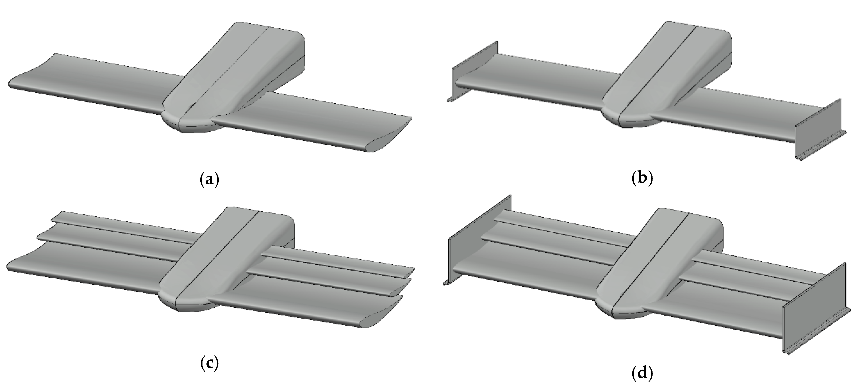
Four baseline configurations (Figure 1) are designed to analyse the influence of flaps and endplates in the aerodynamic and structural performance of the wing. They are based on the optimised bidimensional (2D) three-element configuration achieved by Gorostidi et al. [12] through the analysis of several high-efficiency airfoils and multiple degrees of freedom (chord, attack angles, overlapping between elements, among other minor considerations). The four configurations are extruded 900mm in the spanwise direction, which is the maximum length allowed by the 2022 FIA Formula One regulations to the front wings. Additionally, the baseline configurations are employed to carry out the analysis of the front wing structural components because of the complex shape of the 2022 wing (composed of 21 different 2D sections). After the structural and sensitivity analysis, the selected wing components are implemented in the designed 2022 Formula One front wing. The main features of this bidimensional configuration are provided in Table 2.
The simple one-element configuration (a) provides reference values for further simulations. The second configuration (b) possess endplates which increase the pressure differential over the top and bottom surfaces of the wing, decreasing the induced drag and vortices [23]. The third configuration (c) is designed to analyse the influence of the aspect ratio in the flap structural behaviour and the influence of flaps on the overall wing performance. In the last configuration (d) (three-element wing with endplates), the wingtip devices create a new mechanical ligature between elements, and therefore the structural behaviour of this configuration is similar to Formula One front wings.
2.1.2. Design of 2022 Formula One Front Wing
The 2022 front wing is an adaptation of a three-element bidimensional configuration performed by Gorostidi et al. [12] according to the FIA 2022 Formula One regulations [7]. The volume assigned for the front wing elements (main element and flaps) is derived from Art. A21 is split into 21 sections. The configuration of airfoils in each section is performed through the maximisation of the generated downforce. Thereby, it is important to select the main influence parameters: wing area, attack angle and gap and overlap between elements. The first parameter to modify is the top-view area, which has a proportional influence on the downforce without modifying the two-dimensional optimal configuration. Thereby, the total chord of each section is scaled to match the maximum chord allowed by the front wing reference volume. The second parameter to adapt is the attack angle. Due to the interest in increasing the downforce, it is a parameter to maximise. However, this is only interesting in the sections where the trailing edge position is limited by the length of the reference volume, otherwise the top-view area is decreased. Overall, 18 sections are limited by the length, and therefore their angle is increased to achieve the maximum total attack angle allowed by the maximum volume allowed by Art. A21. On its behalf, the sections limited by height are modified thought the gap and overlap between elements to match the maximum length allowed by the regulations in each section.
Furthermore, more components are added to the wing geometry. In the first place, the endplates are designed through a 90° circular path from the main element satisfying Art. 3.9.2, Art. 3.9.5 and Art. A23. Secondly, a diveplane is added in the endplate external surface following the indications and restrictions explained in Art. 3.9.4, Art. A22 and Art. A25. Lastly, a nose satisfying front bodywork articles (Art. 3.6.1, Art. 3.9.9, Art. 3.11.5, Art. A9 and Art. A11) is designed to analyse the fluid interaction with the wing, but its shape does not fulfil any aerodynamic requirement
2.1.3. Design of Structural Components
Although the current front wings possess a sandwich composite structure with a fibre-reinforced skin and a polymeric interior with inner ribs, this research employs a most conventional structure, based on ribs, spars and skin, similar to commercial aircraft [24]. The internal structure of the wing was submitted to a thorough investigation to analyse the influence of each component in the final structural behaviour, the nature of their main stresses and strains and the influence of the most important design parameters. Firstly, a baseline configuration was designed to obtain a first approach of the wing’s structural behaviour. This configuration is based on qualitative engineering design and it consisted of five ribs, five spars and a skin. Once the baseline configuration is established, several designs were made to analyse their performance. Some of these designs are shown in Figure 3.
The first components to design are the spars, which are the longitudinal beams of the wing. Their main function is to avoid the vertical deformation of the wing and to absorb the loads coming from the skin. They are exposed to shear stress, and, for this case, the shear modulus became a critical factor. The designed spars consist of a normal extrusion along the span width direction, whose section is based on an I beam, which proved to be the best choice in terms of stiffness–weight ratio. The initial number of spars is set in five (four normal I-section beams and one beam in the trailing edge of 10mm width whose section matches the airfoil geometry), whose position is mainly placed in the frontmost part of the wing for two main reasons: pressure distribution is higher near the leading edge and the airfoil S12010 has a much thinner section after the maximum thickness position. However, due to the structural behaviour of the wing, the trailing edge achieves the highest deformation in the wing, and this is the reason why the last spar becomes a critical component in the structure. Another important parameter of the spars is their size. Due to the aforementioned complex cambered airfoil selected, the size of each spar must be adjusted to the environment. Hence, the most suitable approach to parametrise the size of the spars is to set it according to the rib vertical length in each position. Lastly, the spar shape is analysed according to three parameters of freedom: root width, head width and head length (all of them measured as a percentage of the root length). Overall, a total of 324 spar configurations are analysed.
The second components to design are the ribs. They are the transversal element of the wing, whose shape is an airfoil, and they support stiffness to the wing. The ribs are exposed to normal stresses of compression. These stresses can be achieved in the pressure coefficient in each rib, where the maximum load is present in the front part. Besides, the ribs near the tip suffer less load due to the loss of aerodynamic efficiency in the wing. The rib analysis is performed in three degrees of freedom: number of ribs in the structure, thickness and circular holes. The last parameter is essential to the reduction in structural weight because the centre of the ribs is a region with lower stresses. These holes were also decided to be circular because they better absorb the stresses than sharped geometries, such as triangles or squares. Overall, a total of 80 configurations of ribs were investigated. It is very important to notice that each rib has a different volume for each spar set and skin thickness.
Lastly, the skin is the external component of the wing. It is exposed to high flexion loads which depend on the number of ribs and spars of the wing. The skin of an aircraft wing needs to be resistant to corrosion because the coatings increase the structural weight. On the contrary, Formula One wings have a short life expectancy and, therefore, corrosion is not a problem. The skin was created throughout an internal extrusion of the wing surface and it is designed with five different thickness. Even if the thickness of the skin is very small, its volume is the highest of all components, and thereby, it will have enormous importance in the structural design. Additionally, it is important to remark that a bigger thickness provokes a reduction in the section of the rib and spar, which is properly treated in the structural design.
2.1.4. Selection of Front Wing Materials
The selection of the materials is a critical stage in the structural design of a wing. Formula One cars, always immersed in the research and development of new technologies, have improved and changing their materials over the years. They started with metallic structures at the beginning of the Formula One competition in the 1950s, but nowadays they are mostly built of composites [25].
According to the most important physical (density) and mechanical properties (rigidity, yield strength, tensile strength and toughness), three metal alloys are selected and two fibre-reinforced wovens are designed to be implemented in the designed front wings. Thermal and electrical properties, as well as other physical (melting temperature) and mechanical properties (hardness and machinability), are discarded in the material selection process due to their lack of importance in Formula One wing designs.
The metals employed in the wing structure were selected by comparing the mechanical properties of 41 preselected metal alloys (8 steels, 4 cast irons, 9 aluminium alloys, 6 titanium alloys, 8 copper alloys and 6 magnesium alloys) based on several material databases [26,27,28,29,30]. After this analysis, three metal alloys were selected for their implementation in the structural components of the front wing: titanium alloy R54810, which possesses the highest specific Young’s modulus of all preselected alloys (27.46 GPa·cm3/g) and a medium-density (4.37 kg/cm3), magnesium alloy AZ31B, which have a very low density (1.77 kg/cm3) and excellent specific modulus (25.42 GPa·cm3/g) and aluminium alloy 2024 T3, which possesses intermediate properties (specific modulus of 26.29 GPa·cm3/g and density of 2.81 kg/cm3).
The fibre-reinforced composites were designed in several steps. Firstly, 50 ceramic fibres (8 glass fibres, 30 carbon fibres, 8 para-oriented aramid fibres and 4 meta-oriented aramid fibres) and 10 polymeric matrices were investigated (4 thermosetting polymers and 6 thermoplastics) were preselected through several material databases [26,31,32,33,34,35,36]. Secondly, the best two fibres were selected. The first reinforcement choice was carbon fibre: two of them, HS40 and UHMS, possess the highest elasticity modulus (441 GPa) and the same density (1.81 kg/cm3), but HS40 was selected due to its higher tensile strength (4400 MPa vs. 3450 MPa). The second choice was the aramid fibre with the highest mechanical properties: Kevlar K149, which possesses an elasticity modulus of 147 GPa and a very low density (1.47 kg/cm3). Thirdly, assuming that the selected fibres have enough ultimate strength to avoid the composite breaking, the matrices were only selected according to Young’s modulus and the specific Young’s modulus: the first choice was the epoxy polymer, with a Young’s modulus of 6 GPa and a specific Young’s modulus of 4.29 GPa·cm3/g and the second selection was the thermoplastic Polyetherketone (PEK), which possesses a Young’s modulus of 4.6 GPa and a specific Young’s modulus of 3.49 GPa·cm3/g. Lastly, after all considerations and mathematical relationships needed, four composites were created with the two selected fibres (carbon and aramid) and the two selected matrices (Epoxy and PEK) with a 78.5% of fibre volume. The orthotropic mechanical properties and density of the designed composites are provided in Table 3.
2.2. Fluid Conditions
Sea-level fluid conditions were assumed in concordance with the International Standard Atmosphere. Regarding the flow conditions, the velocity of the flow was considered as a one-dimensional streamwise velocity whose magnitude is a typical maximum speed of a Formula One car, where the aerodynamic forces are maximum in the wing. A summary of the fluid and flow conditions is provided in Table 4.
2.3. Mesh Design
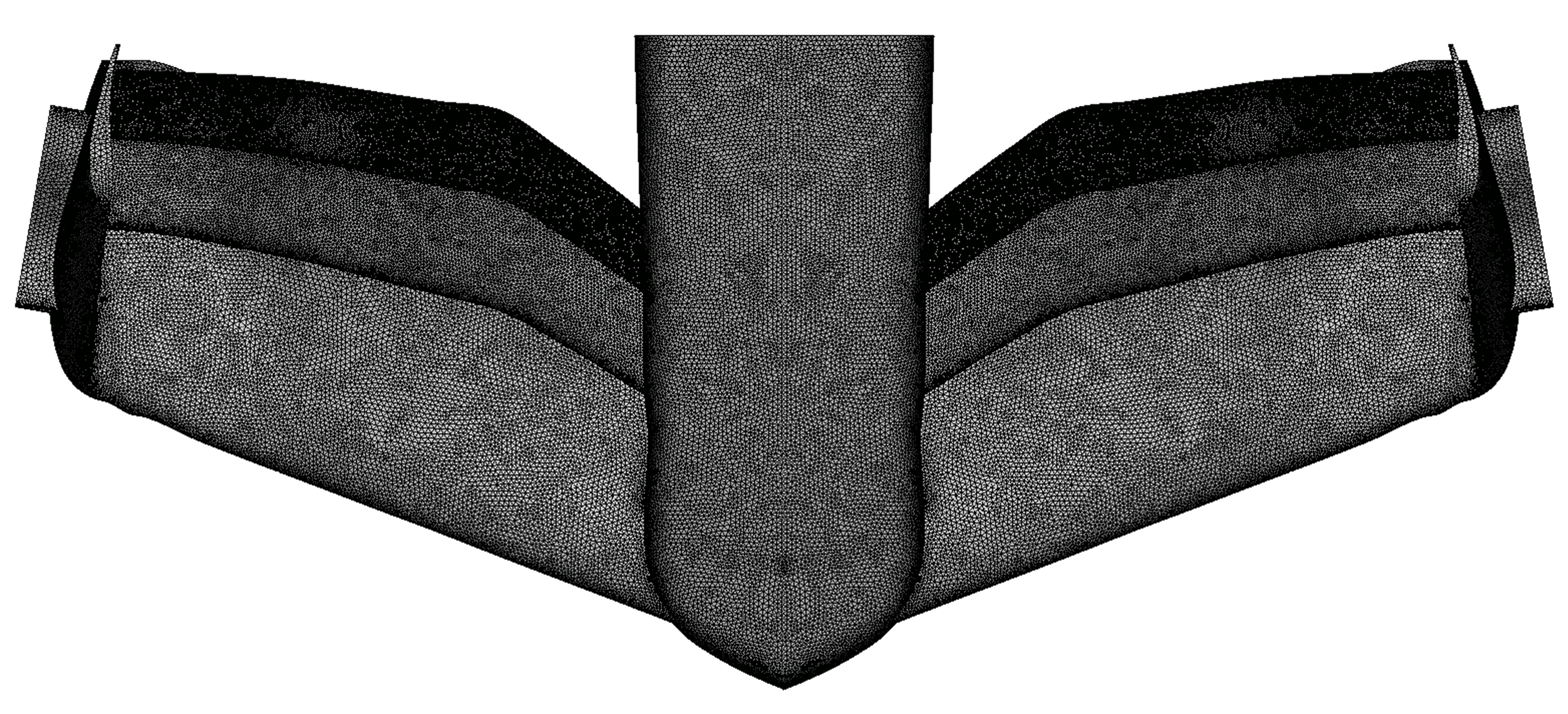
The fluid-dynamic simulations of this research are performed with a hybrid mesh (Figure 4), which is suitable because offers the highest accuracy–cost ratio. It is composed of a structured boundary layer of 30 elements and unstructured methods in the other regions of the domain. On its behalf, the mesh of the inner structure of the front wing is carried out with structured methods (hexahedrons).
The fluid domain selection is one of the most challenging decisions due to the presence of the road under the car. Even if several sizes are used by different authors with accurate results, something is clear: the most suitable topology is a cubical domain. Ashton et al. [37] employed a cubical domain of 8 H height, 14 H wide, 13 H upstream, 19 H downstream and 14 H cross-stream in the analysis of Reynolds-averaged Navier–Stokes (RANS) and detached eddy simulation (DES) methods for realistic automotive models, where H is the height of the car. Heft et al. [38] used the length of the car to set the upstream (2 L) and the downstream (7 L) sizes of the domain. Arrondeau et al. [13] used a fluid domain based on the height in their study of a 2021 F1 front wing. They set 5 H height, 3 H upstream and 10 H downstream. They used the same height as Ashton and a cross-stream length of (11 W). In the most conservative domain, Simmonds et al. [39] employed 10 L height, 20 L wide, 12 L upstream and 15 L downstream. Furthermore, it is important to remark that Ashton et al. [37], Heft [38] and Simmonds [39] did not employ symmetrical boundary conditions in the central plane of the car, implying additional computational cost. In the analysis of the results achieved by the abovementioned authors, the selected fluid domain demonstrates the dimensions employed by Simmonds et al. [39], but using the chord as a relative measurement method. The number of nodes in the airfoil needs to be enough to accurately represent the original geometry and to be considered grid-independent; following the experience of the authors with similar airfoils, 250 nodes were selected. The density of nodes is maximum in the leading edge, with a minimum tangential grid spacing of 0.002, and it is minimum in the maximum thickness location, with a maximum tangential grid spacing of 0.006.
Regarding the boundary layer treatment, ε-based and ω-based models present y+ insensitive wall treatment options through the wall function approach [40]. Using the wall functions, the normal spacing is considered optimal when y+ ≈ 30 (if it is lower, the accuracy of the wall shear stress and the heat transfer can be seriously degraded) [41]. Thereby, a preliminary y+ = 30 and posterior analysis of computed y+ are performed to ensure the correct caption of the boundary layer. The second boundary layer meshing requirement is to ensure its full meshing: the theoretical thickness of the boundary layer is calculated [42] and the number of elements is set as 30 according to Castro [42]. Hence, through mathematical relationships between the abovementioned three parameters (minimum normal grid spacing, maximum thickness and number of elements), the growth rate was set as 1.1. Once all the mesh parameters are obtained, the boundary layer is generated with triangular prisms through a normal extrusion from the wall.
2.4. Numerical Framework
The fluid dynamic analyses were carried out in ANSYS® Fluent (v2019), which employs the finite volume method to solve the partial differential equations governing the fluid dynamic problem. Additionally, decoupled structural analysis were carried out with ANSYS® Mechanical (v2019), a finite element analysis solver (FEA).
Regarding the turbulence models, in the same way as the majority of the engineering simulations, the equations employed in the solver are Reynolds Averaged Navier–Stokes (RANS) equations. These simulations present a lower computational cost than Large Eddy Simulations (LES), which are employed mainly in research fields. All the simulations were carried out with the k-ω SST turbulence model. It is widely used for engineering applications and motorsport aerodynamic designs, being the most important turbulence model in the Formula One fluid dynamic simulation, where an optimal balance between accuracy and time is needed [13].
The fluid dynamic simulations were performed in a coupled incompressible solver based on the SIMPLE algorithm. The iterative scheme significantly affects the computational cost and cost per iteration. Therefore, the coupled pressure-velocity method was set because it has some advantages, such as robustness and efficient single-phase implementation [41]. The coupled scheme is suitable for steady flows. The recommended gradient discretisations are the Least Squares Cell-Based or the Green-Gauss Node Based options. The accuracy between them is similar, but the Least Squares Cell-Based is less expensive to compute [43]. The discretisation of the density, momentum, turbulent viscosity and energy was performed through second-order methods.
The boundary conditions of a Formula One front wing are an important challenge to achieve high accuracy in the fluid dynamic simulations. In a common CFD simulation, the superposition principle is applied. However, it is only valid when the object moving through the air is not near walls. In a Formula One car, the floor is near the wing, and it is very important to make some adjustments to the wall-modelling and boundary conditions.
In order to employ the optimal boundary conditions, the experience of some authors provides important advice. Arrondeau et al. [13] split the ground into two parts in their study of a 2021 Formula One front wing: before the wing, a stationary wall with slip condition was applied and after that, the floor was modelled as a moving wall with a no-slip condition. In the other parts of the domain, they employed a one-directional streamwise velocity for the inlet, outflow for the outlet, with symmetry conditions in the side and upper walls. In the optimisation of a 2020 Formula One front wing, Gorostidi et al. [12] divided the floor into three sections: prior and after the wing, a stationary slip-wall was selected, and under the wing, a no-slip moving wall was set. Besides this, the inlet was a one-directional velocity, the outlet was modelled as pressure-outlet, symmetry was employed in the plane Y = 0, and a slip-wall was set in the opposite sidewall. A different approach to the ground was employed by van den Berg [16] in his analysis of the interaction of a Formula One front wing with the wheels. In this case, all the floor was modelled as a no-slip moving wall. The simulations of the current research were carried out using pressure outlet as outlet, and the side and top planes were modelled with symmetry conditions. The same boundary conditions as van den Berg were used by Heyder-Bruckner [15] in a similar analysis, and the results were compared with the experimental data obtained in a wind tunnel. Simmonds et al. [39] used the same asphalt, inlet and outlet boundary conditions, but they employed slip-walls to the top, and side surfaces (as mentioned, they did not use symmetry conditions in the centre of the car).
The boundary conditions employed are summarised in Table 5: a streamwise velocity of 105 m/s is employed in the inlet of all the simulations and a zero-pressure gradient is selected in the outlet. Symmetry boundary conditions are employed along the plane Y = 0, whose target is to reduce the mesh size by half, and hence to drop the computational cost of the simulations. The asphalt, top and side walls are modelled using the simulations performed by van den Berg [16] and Heyder-Bruckner [15] as a reference, because they were compared with wind tunnel experimental data, achieving high accuracy.
3. Results
3.1. Validation and Verification
When an analysis is performed through computational fluid dynamic and finite element analysis methods, is crucial to ensure the accuracy of the results and to quantify its uncertainty. Hence, an enormous amount of the available time was destined to select the optimal methodology and to establish several validation methods. The most important applied validation methods are the grid convergence analysis, the verification of convergence throughout the aerodynamic coefficients and residuals and the analysis of the boundary layer’s quality. Furthermore, other validation methods were applied, such as the analysis of the pressure transmission between the CFD solver and the FEA solver.
The first validation method is the grid convergence index (GCI) [44,45] developed by Roache [46]. This method applies Richardson extrapolation to determine the order of convergence of the grids and the asymptotic solution of the representative magnitudes. Two additional meshes of the one-element baseline configuration are created to analyse the mesh convergence analysis, whose relative refinement ratio is 2. The GCI is performed through a MatLab® (R2020) file developed by the author [47]. Table 6 provides a summary of the most important parameters of the grid convergence study, including the refinement ratio, the order of convergence, the asymptotic solution and the Grid Convergence Index of the two aerodynamic coefficients.
Additionally, Figure 5 provides the relationship between the aerodynamic coefficients and their asymptotic limit according to the mesh size. As can be observed, the drag coefficient is more influenced by the number of elements of the grid than the lift coefficient because its magnitude is remarkably lower (aerodynamic efficiency of 18.12). However, in grids with more than 5 × 10⁶ elements, the error between the lift and drag coefficients and their grid-independent values is smaller than 1% (0.067% and 0.763%, respectively). After this number of elements, the dependence between results and mesh size can be considered neglectable. Therefore, this mesh size is selected to represent the front wing. More elements would immensely increase the computational cost without any relevant accuracy improvement.
The second validation method consists of ensuring the optimal convergence of the solution, achieving results independent of the iterations of the solver. As mentioned, fluid dynamic simulations need an optimal balance between accuracy and computational cost. In the process, geometries, meshes, numerical schemes and turbulence models need to be adapted to the necessities of the problems and the computational performance available. All these efforts can be disrupted if engineers do not properly analyse the solution convergence and run simulations with thousands of useless iterations in high-performance computing (HPC) facilities. To avoid that, the convergence in preliminary and final simulations was thoroughly analysed throughout aerodynamic forces and residuals. The convergence of results was analysed through the residuals and the value of aerodynamic coefficients according to the iterations. The most important target in the convergence of the equations is to achieve aerodynamic forces independent of the iterations of the solver. This parameter allows for verifying the physical convergence in the simulation: if aerodynamic forces are independent of the iterations, it means that the surface pressure field is invariant, and hence, the velocity field is invariant as well. If aerodynamic forces achieve an equilibrium state in the solution, it means that all the computational domain is converged. Satisfactorily, a very good and fast convergence was achieved due to the high-quality geometries and meshes.
The last validation method consists of analysing if the boundary layer of the airfoils was solved accurately. The computed y+ of every simulation was obtained and compared with the desired value, ensuring that the computed y+ does not exceed 30 at any point on the wing surface.
3.2. Aerodynamic and Structural Analysis of Baseline Wings
The first set of results provides the most important aerodynamic and structural findings of the investigations performed on the four three-dimensional baseline front wings designed in Section 2.1.1. The target is to analyse the main aerodynamic and structural behaviour of a three-element wing with endplates in comparison with a one-element wing without endplates with a similar airfoil, chord and attack angle.
3.2.1. Influence of Flaps and Endplates in the Aerodynamic Performance of the Wings
The aerodynamic objective of the front wing is to achieve maximum negative lift in the front part of the car, to canalise the airstream to the floor, diffuser and other parts of the car, and to reduce the drag generated in the front wheels. However, to analyse the two last benefits it is necessary to perform fluid dynamic simulations of the front wing attached to the other parts of the car, something out of the scope of this research. Hence, the aerodynamic goal is to optimise aerodynamic forces and to analyse the pressure distribution in the wing walls to properly design their internal structure.
Aerodynamic forces are generated by the difference in pressure between the upper and lower surfaces of the wing. Figure 6 provides the pressure distribution in the lower surface of the wing, which possesses negative manometric pressures. The most striking feature is that the negative pressure peak is located near the front bodywork, far away from wingtip effects (circulation of air with different pressures from the upper surface to the lower surface). Additionally, the peak increases with the introduction of endplates and flaps.
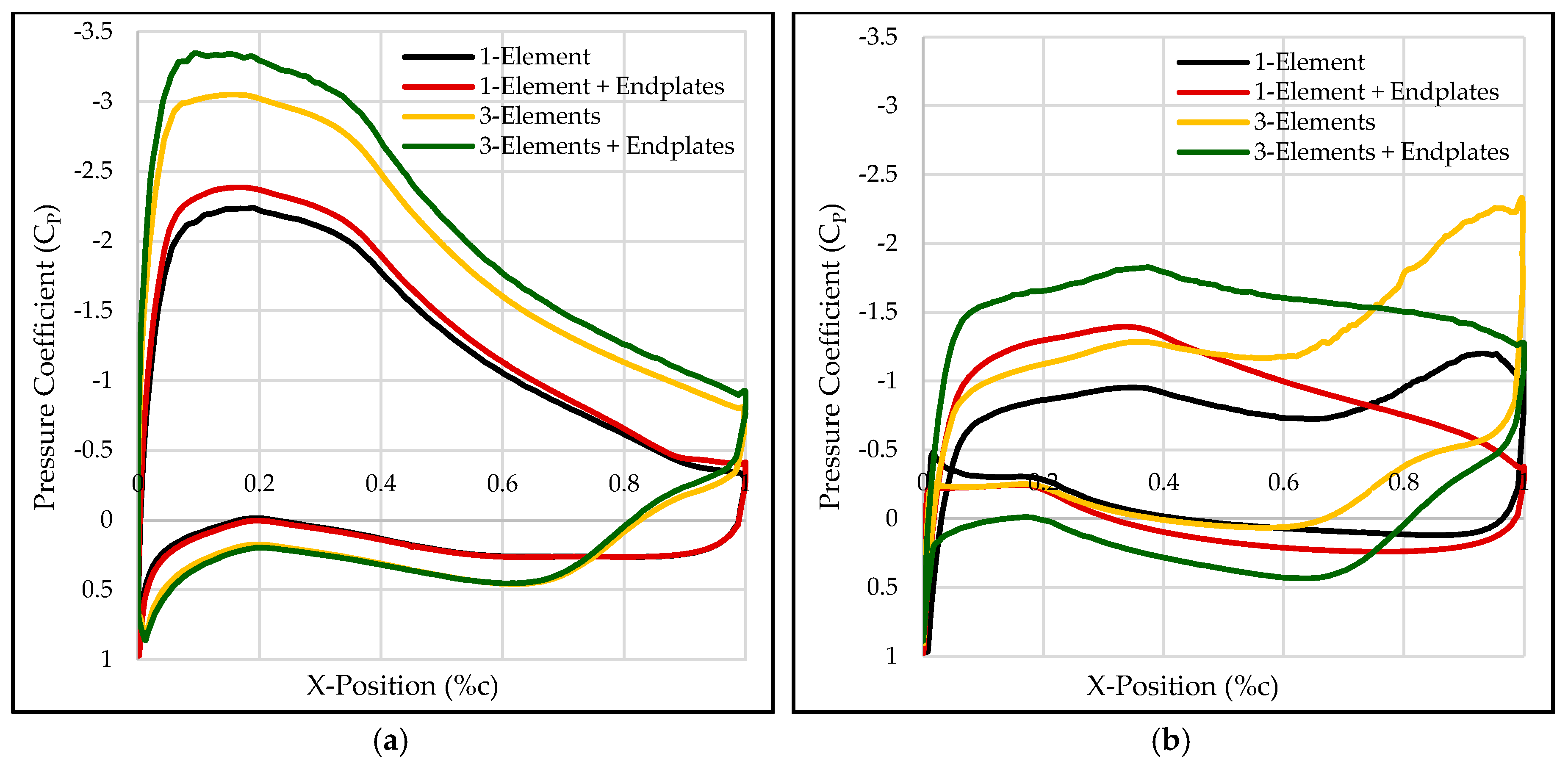
Figure 7 provides the pressure distribution in the surfaces of the first element of the wing at sections 0.05 and 0.95 s (measured in percentage of span width). In all the configurations, near the front bodywork (0.05 s) the wing has an aerodynamic performance more similar to a common 2D airfoil at high attack angle (minimum pressure located in the front part of the suction side with a sudden increment in pressure due to the boundary layer separation). The increment in the variation in pressures is high with the introduction of endplates and very high with the introduction of flaps. Additionally, the three-element configurations possess a reduction in performance in the upper surface near the trailing edge, area highly influenced by the overlapping of the flap. Near the wingtip (0.95 s), each configuration has a different aerodynamic behaviour: configurations with endplates possess a suction peak near the trailing edge due to the air circulation between surfaces and multi-element configurations are affected by the flap in the upper surface near the trailing edge.
The aerodynamic performance of the baseline configurations is assessed through its aerodynamic coefficients (Figure 8). The introduction of endplates in the one-element configuration derives from an increment in the lift coefficient of 12.39% (1.186 vs. 1.333) and decrease in the drag coefficient of 12.28% (0.065 vs. 0.057), provoking an increase in aerodynamic efficiency of 28.70% (23.45 vs. 18.22). The introduction of flaps generated an increment of a 37.69% (1.633 vs. 1.186) in the downforce coefficient (measured in the configurations without endplates). However, the increment in drag was higher (124.61%), which derived from an aerodynamic efficiency loss of 38.47% (11.21 vs. 23.45).
Additionally, it is important to remark that the introduction of flaps increases the top-view area of the front wing by 29.53% (0.62885 vs. 0.48546 m2), and thereby the increment in aerodynamic forces between single-element and multi-element configurations is still higher.
Several conclusions can be extracted from the aerodynamic investigation: the endplates increase the overall aerodynamic performance of the wing, increasing the downforce and decreasing the drag of the front wing. Hence, there are no contraindications of the use of endplates. Meanwhile, the flaps are an effective way to extremely increase the generated downforce, but its introduction generates an increase in the drag of higher magnitude, decreasing the aerodynamic efficiency. Nonetheless, the flaps proved to be a better tool to increase the downforce generated in the wing than the attack angle increment, which derives from the still-higher growth of drag and a possible wing stall, an extremely undesired phenomenon.
3.2.2. Influence of Flaps and Endplates in the Structural Performance of the Wings
The structural analysis of the four baseline configurations is performed through FEA methods. All the configurations possess a structure based on five ribs, five spars and a skin. Additionally, the structural components of the flaps of the three-element configurations are designed with a scale factor proportional to the chord length. The material employed in the structural components is aluminium alloy 2024 T3, the most extended material for aircraft wings [48]. The deformation of the wing follows a linear distribution from the nose ligature to the wingtip. The deformation possesses higher gradient in the trailing edge than in the leading edge. Therefore, the deformation of the configurations is analysed in the upper part of the trailing edge (Figure 9). The one-element configuration without endplates (Figure 9a) presents a maximum deformation of 4.28 mm. With the introduction of endplates (Figure 9b), this deformation is increased by 28.73% (5.51 mm) but followed the same distribution. The three-element configuration without endplates (Figure 9c) experiences an important increment of 44.85% in the maximum deformation of the main element due to the increase in aerodynamic forces in the wing. However, the most critical feature of the configuration is the maximum deformation in the secondary flap (110.25 mm). This element, although present in smaller loads in its surface, suffers the effects of the components scaling without a reduction in spanwise size (increasing the aspect ratio). This configuration is unacceptable because the secondary flap crashes with the primary flap (distance between elements of 16.27 mm and overlapping of 35.46%). Finally, the introduction of endplates in the multi-element configuration (Figure 9d) provokes a different structural behaviour. Firstly, it is noticeable than the deformation of all elements along the spanwise direction is not proportional, and hence the position of the maximum relative distance between elements is located at y = 0.55 m. Secondly, the maximum deformation of the second flap (7.68 mm) is located at y = 0.743 m, and in the main element and primary flap, it is located in the wingtip (6.84 and 7.14 mm, respectively). Lastly, the deformation in the endplate ligature is different for each element (6.84, 7.14 and 7.27 mm) because the endplate is undergoing an internal deformation along the Z-direction. This deformation comes from the high normal loads (traction) provoked by the difference in deformations of the wing elements in the configuration without endplates (Figure 9c). Hence, the introduction of endplates in a multi-element configuration generates a new mechanical ligature between the wing elements, and hence the behaviour of the wings is analogous to a bi-embedded beam with some differences: Firstly, the endplate is a ligature between the elements but its position is not fixed, and secondly, the low thickness of the endplate derives from internal deformations. Therefore, the maximum deformation of the elements is not necessarily in the wingtip, and also its deformation in the wingtip is not certainly the same.
3.3. Structural Analysis of Front Wing Components
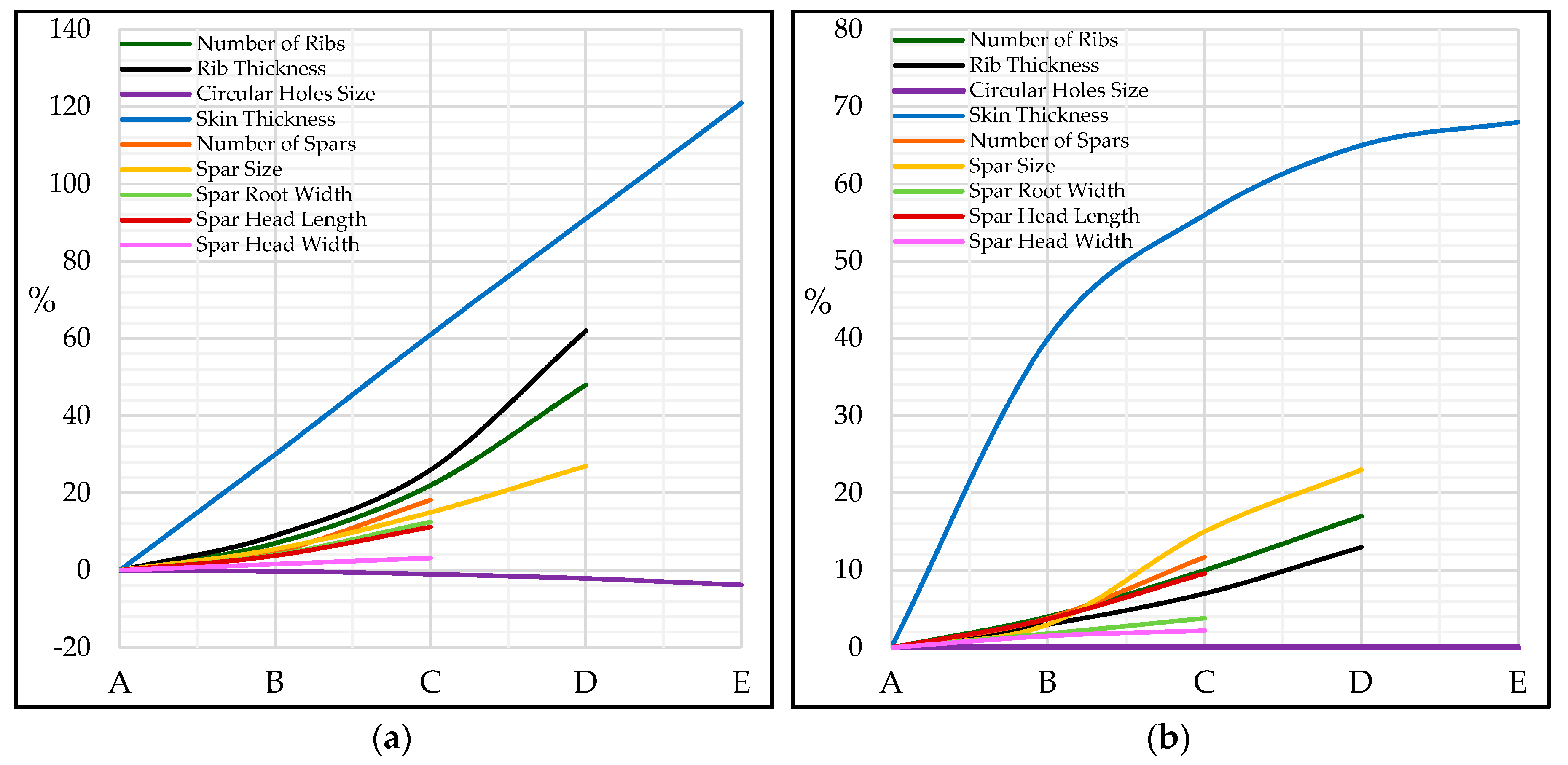
The structural investigation consists of analysing the structural behaviour of the internal wing components: spars, ribs and skin. The degrees of freedom of the structural design are the number of ribs (A = 3, B = 5, C = 9 and D = 17), rib thickness (A = 2.5 mm, B = 5 mm, C = 10 mm and D = 20 mm), the circular holes implemented in the ribs (A = without holes, B = 20%, C = 40%, D = 60% and E = 80%), the number of spars (A = 4, B = 5 and C = 8), spar size (A = 20%, B = 40%, C = 60% and D = 80%), spar root width (A = 5%, B = 10% and C = 20%), spar head length (A = 10%, B = 50% and C = 100%), spar head width (A = 5%, B = 10% and C = 20%) and skin thickness (A = 0.5 mm, B = 1 mm, C = 1.5 mm, D = 2 mm and E = 2.5 mm). A total of 129,600 combinations were achieved from the investigation of the structural components to the posterior sensitivity analysis.
Figure 10 provides the variation in maximum deformation and structural weight in the aforementioned degrees of freedom. The parameters with more influence in the deformation and weight of the wing are the skin thickness, rib thickness and the number of ribs. On the opposite side, the width of the spar section and the circular holes implemented in the skin possess a low influence. In terms of deformation–weight ratio, the circular holes offer a perfect balance because they reduce the weight without an increase in deformation. All the data obtained were used as an input of the structural sensitivity analysis (Section 3.5).
3.4. Analysis of Materials
The three selected alloys (Titanium R54810, aluminium 2024 T3 and magnesium AZ31B), the carbon-reinforced composite (HS40-Epoxy) and the aramid-reinforced composite (Kevlar K149-Epoxy) were implemented in the structural components to analyse their performance. Both composite wovens were placed properly in each component to achieve the best efficacy. Additionally, due to the complex shape of the spars (I-section), the carbon-reinforced composite (HS40-Epoxy) and the aramid-reinforced composite (Kevlar K149-Epoxy) were discarded instead of implemented. The analysis of materials is decoupled for each structural component.
Table 7 gives the weight and maximum deformation of the wing according to the component material. Due to the orthotropic properties of the fibre-reinforced composites, the most rigid material depends on the structural composites: the wing with ribs made of titanium R54810 possessed the minimum deformation (4.25 mm) and the wing with skin made of a carbon–epoxy composite achieved the minimum deformation (2.33 mm). The data obtained were the input of the structural sensitivity analysis.
Additionally, the mechanical investigation proved that skin is exposed to the highest normal loads, mainly in its mechanical ligature with the front bodywork. Furthermore, it is exposed to high-flexion stresses which directly depend on the number of ribs and spars and the skin thickness. Therefore, this is the component with the highest fluctuation according to the analysed configuration. The ribs, the component whose main target is to transmit loads from the skin to the spars, is the structural element most exposed to normal stresses of compression. Lastly, due to the overall structural behaviour of the 2022 front wing, similar to a bi-embedded beam, the spars are the component most exposed to shear stresses.
3.5. Sensitivity Analysis of Wing Structure
The geometrical design and materials of the structural components of the Formula One 2022 front wing are selected through a sensitivity analysis. The objective is to design the lightest structure whose maximum deformation is lower than 2 mm in the most deformed position. The degrees of freedom are the number of ribs, rib thickness, the circular holes implemented in the ribs, the number of spars, spar size, spar root width, spar head length, spar head width, skin thickness, spar material, ribs material and skin material. The sensitivity analysis performed in each wing element is decoupled, and therefore a total of 29.16 million combinations are possible. The selection of the most suitable wing structural components can be summarised in three steps.
The first step consists of setting the most rigid combination of each degree of freedom. Thereby, it is possible to obtain the least deformed structure inside the structural and material combinations analysed. This value is equal to 1.61 mm in the main element, 1.68 mm in the primary flap and 1.80 mm in the secondary flap. Once a preliminary structure satisfying the deformation limitation established in the objectives (2 mm) is obtained, the reduction in weight is carried.
The second step consists of obtaining the weight-deformation variation gradient, shown in Table 8. These values are achieved through several applied mathematics relationships between sequential configurations in each degree of freedom of the data obtained (Figure 10). Hence, the values provided represent the sensitivity of the wing in terms of deformation and weight when a lighter combination is implemented. As can be observed, the best measure to implement in the structure is the introduction of circular holes in the structure, which reduces the structural weight without an increase in deformation. Other good measures are the introduction of lighter materials in the ribs and the reduction in rib thickness. On the contrary, the reduction in the skin thickness, spars size and the introduction of lighter materials in the skin are the worst measures to reduce structural weight.
Once the gradient table is made, the methodology of the sensitivity analysis consists of selecting the combinations with the highest gradient until the maximum established deformation value is reached. Two main restrictions are applied to ensure the viability and robustness of the model. Firstly, the sensitivity analysis is performed sequentially. Secondly, if the highest gradient variation provokes a higher maximum deformation than the applied restriction, it is discarded and the next highest gradient is implemented. The features of the selected mechanical components of the main element and flaps are presented in Table 9, including the expected deformation.
3.6. Formula One 2022 Front Wing
Finally, the aerodynamic and structural parametrical studies of the designed 2022 front wing (Section 2.1.2) are carried out. The aerodynamic performance of the 2022 wing is evaluated through the distribution of pressures in the wing and the aerodynamic coefficients. Comparing them with the baseline three-element configuration with endplates, it is possible to understand and assess how 2022 technical rules influence the front wing performance. The structural analysis is carried out with the structural components selected in Section 3.5 and shown in Figure 11.
Due to the geometric complexity of the front wing, each element was designed in detail: each rib possesses a particular shape, and, consequently, the relative measures and dimensions used to design the spars and circular holes are different. In order to achieve maximum structural performance, each spar and hole was designed specifically to match the position assigned and their dimensions were set based on the rib thickness of each position. Hence, each one of the 51 aramid-epoxy ribs, 21 titanium spars and 306 circular holes possesses unique dimensions.
Figure 12 provides the distribution of pressure in the lower and upper surfaces of the front wing elements. The pressure field, which possesses all the aerodynamic phenomena explained in Section 3.2.1, presents some interesting features to analyse. Firstly, the low-pressure region in the lower surface of the main element has a bigger magnitude and its adverse gradient along the spanwise direction is slower. The reason behind this performance is the increment of chord and attack angle in the central sections of the wing. Therefore, the 2022 wing does not present the minimum pressure near the front bodywork (it is located at 0.47 s). Besides, the volume assigned for the front wing in the Article A21 of the 2022 FIA Formula One regulations possesses a negative dihedral angle from y = 0.125 m to y = 0.900 m of φ = 2.586°. Hence, the airfoils located near the airfoil possess a smaller distance to the asphalt, rising the ground effect. Lastly, the rear part of the upper surface of the main element near the wingtips possesses negative manometric pressure. This is the consequence of the maximisation of the area allowed by the regulations and the endplate design. However, although this is an undesired effect, the maximisation of the area allows very high negative pressures in the leading edge of the wing near the wingtip. Besides, the benefits of the area maximisation near the wingtip possess a higher magnitude than the negative effects of the excessive overlapping.
Figure 13 gives the pressure distribution of the 2022 front wing in the sections 0.05 and 0.95 s. Focused in the airfoils located near the front bodywork, the minimum pressure in the lower surface is achieved near the leading edge (0.0617c), where it achieves a peak of −27,100 Pa. After this position, the lower surface experiences a pressure increment of constant gradient until the trailing edge, where it reaches a value of −6711.3 Pa. Its behaviour is slightly different from the baseline three-element configuration with endplates, where the peak in minimum pressure is located in a more convex surface, but with a noticeably slower peak (−22,602.3 Pa). However, the upper surface of the main element and the flaps possess similar aerodynamic features. The airfoils near the wingtip presents the worst aerodynamic performance for three reasons: they possess a low attack angle (α = 13.02°) and chord (c = 554.29 mm), they are influenced by the negative effects of the wingtip, and the overlapping between elements reaches a critical value. Hence, its minimum pressure is highly affected and the upper surface of the main element reaches negative manometric pressures after 50% of the chord.
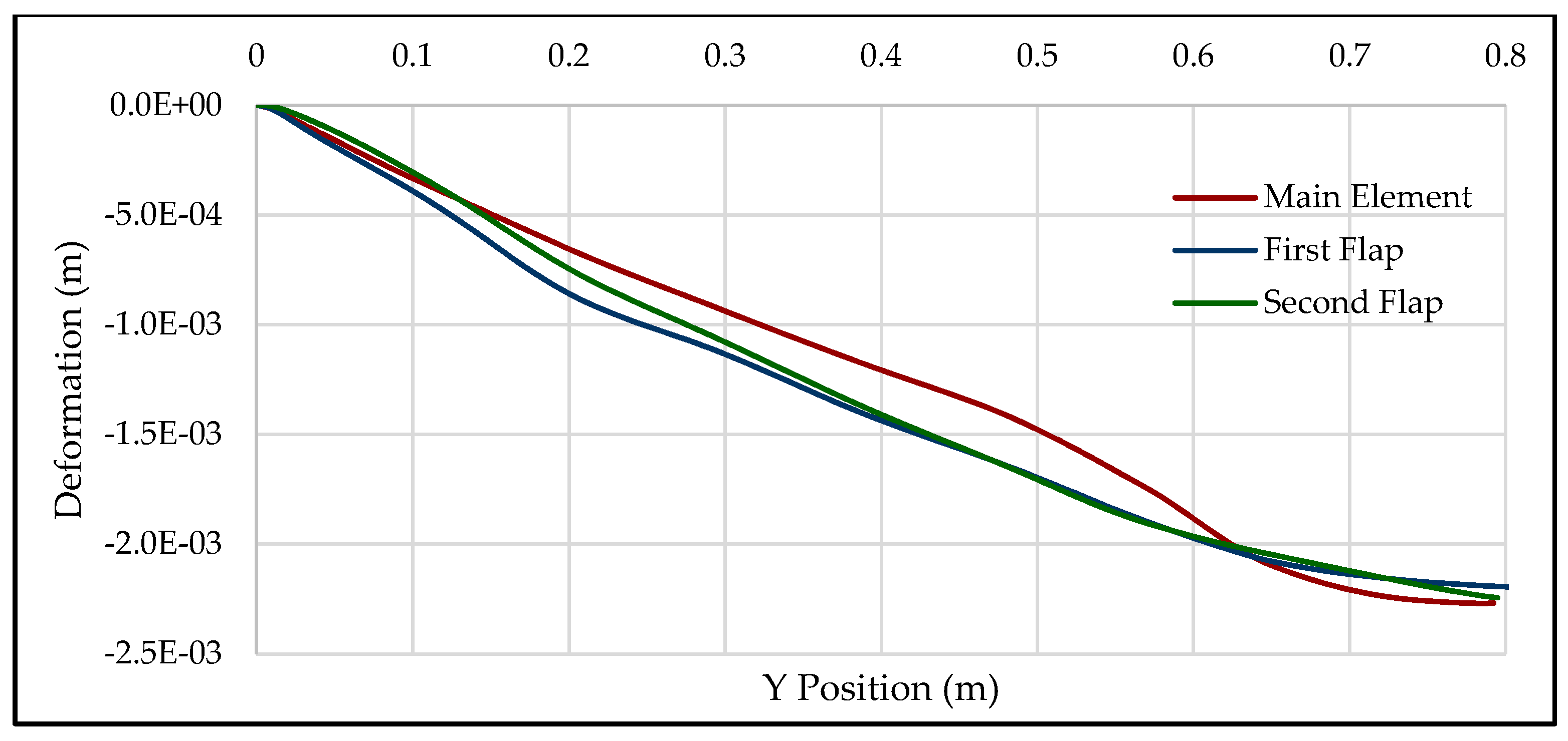
The most important parameter to analyse is the Z-direction deformation (Figure 14 and Figure 15). Due to the complex shape of the wing, the deformation does not follow an exactly linear path. The maximum relative deformation between components is 0.31 mm at Y = 0.453 m. This low number ensures the negligible variation in aerodynamic performance under big loads because the elements possess an extremely small variation according to the optimised gap and overlapping between elements. The maximum deformation of the main element, primary flap and the secondary flap is 2.26, 2.19 and 2.24 mm, respectively. Comparing these deformations with the expected deformations (Table 9), the difference is 14.14%, 10.66% and 13.70%. These differences are mainly originated by the particular features of the 2022 high-performance front wing. Additionally, using the gradient method it is possible to know the best way to reduce the deformation or to reduce the structural weight in each element, depending on the engineering purposes. In this development, a target of maximum deformation in the wing of 2 mm was established, but there is not a general requirement. Moreover, the velocity employed in the analysis was the historical maximum velocity achieved by a Formula One car, and hence the designed structure satisfies the established target in most of the tracks. Due to all these reasons, there is not any advantage of modifying and generating a new structural design.
4. Conclusions
This research provides interesting observations regarding the aerodynamic and structural performance of multi-element wings with wingtip devices that can be useful to readers fascinated by Formula One aerodynamic devices and readers interested in building their own wing who want to have a starting point to analyse the structural behaviour of the wing, such as Formula Student engineers. Besides, the research brings knowledge about the influence of the 2022 FIA Formula One regulations on the wing performance.
Several conclusions about multi-element structural designs can be achieved. Firstly, the deformation of a wing is extremely affected by the aspect ratio, and therefore, in a three-element wing, the secondary flap suffers a bigger deformation, which needs to be compensated with structural components or materials of higher rigidity. In this research, the second flap possesses four times more aspect ratio than the main element (7.2 vs. 1.8) which derives from a variation in maximum deformation 17.81 times (110.25 vs. 6.19 mm) when they possess the same components and materials. Secondly, the endplates create a mechanical ligature between the elements of the wing, changing their mechanical behaviour from an embedded beam to a bi-embedded beam. When wingtip devices are employed, the wing element of lower aspect ratio (1.8) experiences an increasing light deformation (from 6.19 to 6.84 mm), and the element with a higher aspect ratio (7.2) experiences a remarkable decreasing deformation (from 110.25 to 7.68 mm) Additionally, this mechanical ligature is mobile, and consequently the position of the maximum deformation of the wings is located in the secondary flap at 0.743 s and not in the centre of the wingspan width. Regarding the structural components, the best way to reduce weight in a wing is to introduce circular holes in the centre of the ribs, because this does not affect the deformation. Besides, the skin thickness in a wing made of spars, ribs and skin possesses a high influence on the deformation (12.52 mm when skin thickness is 0.5 mm, and 3.56 mm when skin thickness is 2.5 mm) and the weight (4.013 kg when skin thickness is 0.5 mm, and 8.958 kg when skin thickness is 2.5 mm) of the wing. Lastly, it is possible to apply the superposition principle in a structural design, allowing the analysis of millions of configurations with accurate results.
The 2022 Formula One regulations have a big influence on the aerodynamic and structural performance of the front wing. Firstly, they provoke a bad aerodynamic performance near the wingtip due to the new endplates and their influence on the bidimensional configuration of the wing near the endplate. Secondly, the designed 2022 front wing presents a minimum pressure at 0.47s due to the volume assigned in the Article A21 of the 2022 FIA Formula One regulations: the wing possesses a negative dihedral angle from y = 0.125 m to y = 0.900 m of φ=2.586º, increasing the ground effect and, additionally, the central sections have a higher chord and attack angle. Lastly, the flaps of the 2022 F1 undergo deformations and stresses of remarkably lower magnitude than embedded flaps (2020 front wing style), something observed in the baseline configurations.
Author Contributions
Z.A.R. and X.C. performed investigations into the concept. X.C. performed numerical analysis and mesh generation. X.C. obtained the results and performed analysis and visualisations. Z.A.R. provided supervision and guidance to the whole research, including analysis of data and post-processing. All authors have read and agreed to the published version of the manuscript.
Funding
This research received no external funding.
Acknowledgments
All the simulations are performed using Cranfield High-Performance Computing Cranfield HPC) facility. We acknowledge the support received from Mick Knaggs from Cranfield HPC during the simulation process.
Conflicts of Interest
The authors declare no conflict of interest.
References
- Katz, J. Race Car Aerodynamics: Designing for Speed; R. Bentley: Cambridge, MA, USA, 1995; ISBN 978-0-8376-0142-7. [Google Scholar]
- Lau, C.S.; Srigrarom, S. Flow field around the front wing of Formula One racing car model: BAR Honda 003 and MP4-21 under ground effect. Int. J. Aerodyn. 2010, 1, 72–81. [Google Scholar] [CrossRef]
- Seljak, G. Race Car Aerodynamics; University of Ljubljana: Ljubljana, Slovenia, 2008. [Google Scholar]
- Castro, X. Diseño, Optimización y Análisis Aerodinámico de un Fórmula 1; Universidad Rey Juan Carlos: Móstoles, Spain, 2018. [Google Scholar]
- Wright, P.; Matthews, T. Formula 1 Technology; SAE International: Warrendale, PA, USA, 2001; ISBN 978-0-7680-2887-4. [Google Scholar]
- Obeid, S.; Jha, R.; Ahmadi, G. RANS Simulations of Aerodynamic Performance of NACA 0015 Flapped Airfoil. Fluids 2017, 2, 2. [Google Scholar] [CrossRef] [Green Version]
- 2022 Formula One Technical Regulations. In Proceedings of the Fédération Internationale de l’ Automobile, Paris, France, 30 October 2019. Iss 2.
- Landvogt, B. Fluid-Structure Interaction of Racing Car Spoilers. In Proceedings of the NAFEMS European Conference: Multiphysics Simulation, Copenhagen, Denmark, 15–16 November 2016. [Google Scholar]
- McBeath, S. Competition Car Aerodynamics; Veloce Publishing Limited: Dorset, UK, 2015; ISBN 978-1-78711-086-1. [Google Scholar]
- Reynolds, J. 2021 F1 Rules: The Key Changes Explained|Formula 1®. Available online: https://www.formula1.com/en/latest/article.2021-f1-rules-the-key-changes-explained.2dCtCkxNofk20K1B4rJwTk.html (accessed on 4 June 2020).
- Petrone, G.; Hill, C.; Biancolini, M. Track by track robust optimization of a F1 front wing using adjoint solutions and radial basis functions. In Proceedings of the 32nd AIAA Applied Aerodynamics Conference, Atlanta, GA, USA, 16–20 June 2014; American Institute of Aeronautics and Astronautics: Atlanta, GA, USA, 2014. [Google Scholar]
- Gorostidi, N.; Lecourt, D.; Castro, X.; Maigler, M. Optimisation of Aerofoil Design; Cranfield University: Cranfield, UK, 2020. [Google Scholar]
- Arrondeau, B.; Saravana, A.; Sabatés, A.; Daniela, S. Front Wing Design of a 2021 F1 Race Car; Cranfield University: Cranfield, UK, 2020. [Google Scholar]
- Syazrul, M. Study of F1 Car Aerodynamics Front Wing Using Computational Fluid Dynamics (CFD); Universiti Malaysia Pahang: Gambang, Malaysia, 2010. [Google Scholar]
- Heyder-Bruckner, J. The Aerodynamics of an Inverted Wing and a Rotating Wheel in Ground Effect; University of Southampton: Southampton, UK, 2011. [Google Scholar]
- van den Berg, M.A. Aerodynamic Interaction of an Inverted Wing with a Rotating Wheel; University of Southampton: Southampton, UK, 2007. [Google Scholar]
- Azmi, A.R.S.; Sapit, A.; Mohammed, A.N.; Razali, M.A.; Sadikin, A.; Nordin, N. Study on airflow characteristics of rear wing of F1 car. IOP Conf. Ser. Mater. Sci. Eng. 2017, 243, 012030. [Google Scholar] [CrossRef] [Green Version]
- Bhatnagar, U.R. Formula 1 Race Car Performance Improvement by Optimization of the Aerodynamic Relationship between the Front and Rear Wings; The Pennsylvania State University: State College, PA, USA, 2014. [Google Scholar]
- Ahlfeld, R.; Ciampoli, F.; Pietropaoli, M.; Pepper, N.; Montomoli, F. Data-driven uncertainty quantification for Formula 1: Diffuser, wing tip and front wing variations. Proc. Inst. Mech. Eng. Part D J. Automob. Eng. 2019, 233, 1495–1506. [Google Scholar] [CrossRef]
- Chirco, L.; Manservisi, S. On the Optimal Control of Stationary Fluid–Structure Interaction Systems. Fluids 2020, 5, 144. [Google Scholar] [CrossRef]
- Dillinger, J.K.S.; Meddaikar, Y.M.; Lübker, J.; Pusch, M.; Kier, T. Design and Optimization of an Aeroservoelastic Wind Tunnel Model. Fluids 2020, 5, 35. [Google Scholar] [CrossRef] [Green Version]
- Pedrol, E.; Massons, J.; Díaz, F.; Aguiló, M. Two-Way Coupling Fluid-Structure Interaction (FSI) Approach to Inertial Focusing Dynamics under Dean Flow Patterns in Asymmetric Serpentines. Fluids 2018, 3, 62. [Google Scholar] [CrossRef] [Green Version]
- Zhao, L.; Shkarayev, S.; Su, E. Aerodynamics of a Wing with a Wingtip Flapper. Fluids 2018, 3, 29. [Google Scholar] [CrossRef] [Green Version]
- Megson, T.H.G. Aircraft Structures for Engineering Students, 3rd ed.; Arnold: London, UK, 1999; ISBN 978-0-340-70588-9. [Google Scholar]
- Savage, G. Honda Racing F1 Team. 2008. Available online: http://www.formula1-dictionary.net/ (accessed on 8 December 2020).
- Callister, W.D.; Rethwisch, D.G. Materials Science and Engineering: An Introduction, 10th ed.; Wiley: Hoboken, NJ, USA, 2018; ISBN 978-1-119-40539-9. [Google Scholar]
- ASM International (Ed.) ASM Handbook, 10th ed.; ASM International: Materials Park, OH, USA, 1990; ISBN 978-0-87170-377-4. [Google Scholar]
- AZO Materials: Material Science News Materials Engineering News. Available online: https://www.azom.com/ (accessed on 25 July 2020).
- MatWeb: Online Materials Information Resource. Available online: http://www.matweb.com/ (accessed on 29 July 2020).
- ASM Aerospace Specification Metals, Inc. Florida Aerospace Metal Distributor. Available online: https://www.aerospacemetals.com/ (accessed on 26 July 2020).
- MakeItFrom.com: Material Properties Database. Available online: https://www.makeitfrom.com/ (accessed on 28 July 2020).
- ResearchGate: Find and Share Research. Available online: https://www.researchgate.net/ (accessed on 30 July 2020).
- Gabara, V. High-resistance fibers. In Ullmann’s Encyclopedia of Industrial Chemistry; Wiley-VCH Verlag GmbH & Co. KGaA: Weinheim, Germany, 2000; p. a13_001. ISBN 978-3-527-30673-2. [Google Scholar]
- Omnexus: The Material Selection Platform. Free Online Database for Plastic Industry. Available online: https://omnexus.specialchem.com (accessed on 1 August 2020).
- Polymer Properties Database: Free Encyclopedia of Polymer Science and Technology. Available online: http://polymerdatabase.com/home.html (accessed on 2 August 2020).
- Ensigner Plastics: High Performance Plastic Solutions. Available online: https://www.ensingerplastics.com/en (accessed on 31 July 2020).
- Ashton, N.; West, A.; Lardeau, S.; Revell, A. Assessment of RANS and DES methods for realistic automotive models. Comput. Fluids 2016, 128, 1–15. [Google Scholar] [CrossRef] [Green Version]
- Heft, A.I.; Indinger, T.; Adams, N.A. Experimental and numerical investigation of the DrivAer model. In Proceedings of the ASME 2012 Fluids Engineering Division Summer Meeting collocated with the ASME 2012 Heat Transfer Summer Conference and the ASME 2012 10th International Conference on Nanochannels, Microchannels, and Minichannels. Volume 1: Symposia, Parts A and B, Rio Grande, PR, USA, 8–12 July 2012; pp. 41–51. [Google Scholar]
- Simmonds, N.; Pitman, J.; Tsoutsanis, P.; Jenkins, K.; Gaylard, A.; Jansen, W. Complete Body Aerodynamic Study of Three Vehicles; SAE Technical Paper 2017-01-1529; SAE International: Warrendale, PA, USA, 2017. [Google Scholar] [CrossRef] [Green Version]
- Lisejkin, V.D. Grid generation methods. In Scientific Computation, 3rd ed.; Springer: Cham, Switzerland, 2017; ISBN 978-3-319-57846-0. [Google Scholar]
- ANSYS Fluent User’s Guide; Release 19.2; ANSYS Inc.: Canonsburg, PA, USA, 2013.
- Castro, X. Grid Generation & CAD; Cranfield University: Cranfield, UK, 2020. [Google Scholar]
- ANSYS Fluent Theory Guide; Release 19.2; ANSYS Inc.: Canonsburg, PA, USA, 2013.
- Kwaśniewski, L. Application of grid convergence index in FE computation. Bull. Pol. Acad. Sci. Tech. Sci. 2013, 61, 123–128. [Google Scholar] [CrossRef] [Green Version]
- NPARC Alliance-Policies and Plans; NASA Glenn Research Centre. Available online: https://www.grc.nasa.gov/www/wind/plans/Policies_and_Plans.pdf (accessed on 8 December 2020).
- Roache, P.J. Verification and Validation in Computational Science and Engineering; Computing in Science; Hermosa Publishers: Socorro, NM, USA, 1998. [Google Scholar]
- Castro, X. GCI Solver; Cranfield University: Cranfield, UK, 2020. [Google Scholar]
- Dubourg, L.; Merati, A.; Jahazi, M. Process optimisation and mechanical properties of friction stir lap welds of 7075-T6 stringers on 2024-T3 skin. Mater. Des. 2010, 31, 3324–3330. [Google Scholar] [CrossRef]
Figure 1.
Baseline configurations: (a) one-element without endplates; (b) one-element with endplates; (c) three-element without endplates; (d) three-element with endplates.
Figure 1.
Baseline configurations: (a) one-element without endplates; (b) one-element with endplates; (c) three-element without endplates; (d) three-element with endplates.

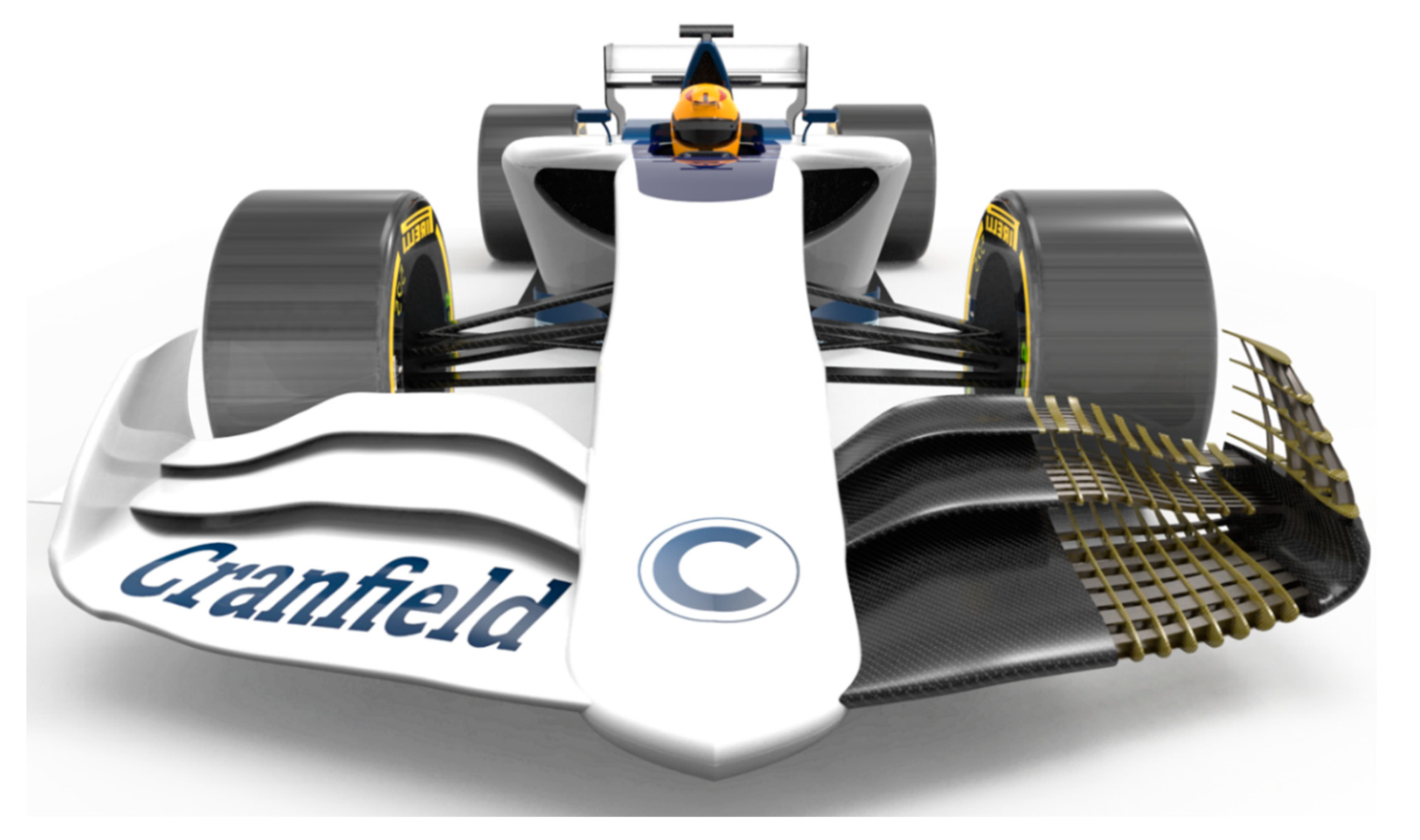
Figure 2.
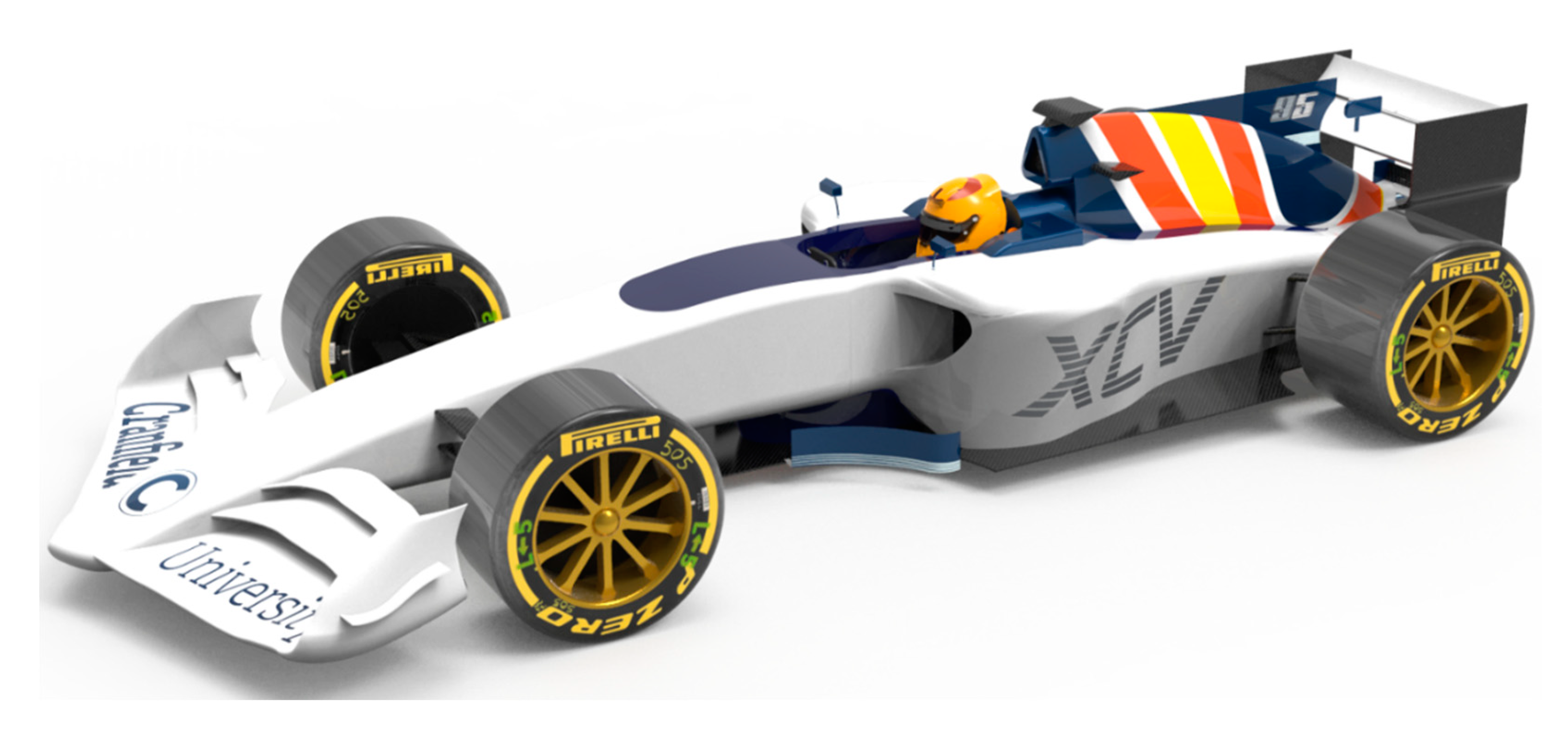
2022 front wing attached to a 2018 Formula One car (the whole design is performed and developed by the authors).
Figure 2.
2022 front wing attached to a 2018 Formula One car (the whole design is performed and developed by the authors).

Figure 3.
Examples of wing structural designs: (a) wing structure with high-density ribs; (b) ribs with implemented circular holes; (c) wing structure with high-density spars; (d) ribs with high thickness.
Figure 3.
Examples of wing structural designs: (a) wing structure with high-density ribs; (b) ribs with implemented circular holes; (c) wing structure with high-density spars; (d) ribs with high thickness.

Figure 4.
Mesh of the 2022 Formula One front wing assembly.

Figure 5.
Approximation of the aerodynamic coefficients according to the grid size.

Figure 6.
Distribution of pressure in the lower surface of (a) one-element without endplates; (b) one-element with endplates; (c) three-element without endplates; (d) three-element with endplates.
Figure 6.
Distribution of pressure in the lower surface of (a) one-element without endplates; (b) one-element with endplates; (c) three-element without endplates; (d) three-element with endplates.

Figure 7.
Pressure distribution in baseline configurations at sections: (a) 0.05 s; (b) 0.95 s.

Figure 8.
(a) Lift coefficients; (b) Drag coefficients.

Figure 9.
Z-Position of the trailing edge along with spanwise direction in (a) one-element without endplates; (b) one-element with endplates; (c) three-element without endplates; (d) three-element with endplates.
Figure 9.
Z-Position of the trailing edge along with spanwise direction in (a) one-element without endplates; (b) one-element with endplates; (c) three-element without endplates; (d) three-element with endplates.

Figure 10.
Increment in weight (a) and reduction in deformation (b) according to the structural configuration.
Figure 10.
Increment in weight (a) and reduction in deformation (b) according to the structural configuration.

Figure 11.
Selected structural components of the Formula One 2022 front wing.

Figure 12.
Pressure field in lower (a) and upper (b) surfaces of the Formula One 2022 front wing.

Figure 13.
Pressure distribution in the three elements of the 2022 F1 front wing at sections: (a) 0.05 s; (b) 0.95 s.
Figure 13.
Pressure distribution in the three elements of the 2022 F1 front wing at sections: (a) 0.05 s; (b) 0.95 s.

Figure 14.
Z-deformation in the trailing edge of the Formula One 2022 front wing.

Figure 15.
Z-deformation measured in meters of the Formula One 2022 front wing.


Table 1.
2022 FIA Formula One Technical Regulations [7].
Table 1.
2022 FIA Formula One Technical Regulations [7].
| Parameter | Articles |
|---|---|
| Front Bodywork | Art. 3.6.1, Art. 3.9.9 and Art. 3.11.5 |
| Front Wing Airfoils | Art. 3.9.1 |
| Front Wing Endplates | Art. 3.9.2 and Art. 3.9.5 |
| Front Wing Tip | Art. 3.9.3 |
| Front Wing Diveplane | Art. 3.9.4 |
| Front Wing Assembly | Art. 3.9.6 |
| Materials | Art. 15.3.1, Art. 15.3.2, Art. 15.3.3 and Art. 15.3.4 |
| Coordinate Systems, Reference Surfaces and Reference Volumes | Art. 2.9.1, Art. 2.9.2, Art. 2.9.3, Art. 2.9.4, Art. 2.11.1, Art. 2.11.2, Art. 2.11.3, Art. 3.4.1, Art 3.4.2, Art 3.4.3, Art. 12.1.4, Art. A.9, Art. A.12, Art. A.21, Art A.22, Art. A23, Art. A24, Art. A25 and Art. A26. |
Table 2.
Features of bidimensional three-element F1 front wing achieved by Gorostidi et al. [11].
Table 2.
Features of bidimensional three-element F1 front wing achieved by Gorostidi et al. [11].
| Feature | Symbol | Value | Units |
|---|---|---|---|
| Airfoil | S1210 | - | - |
| Chord of Main Element | 250 | mm | |
| Chord of Primary Flap | 125 | mm | |
| Chord of Secondary Flap | 62.5 | mm | |
| Attack Angle of Main Element | 3 | ° | |
| Attack Angle of Primary Flap | 6 | ° | |
| Attack Angle of Secondary Flap | 9 | ° | |
| Gap between elements 1 and 2 | 19.43 | mm | |
| Gap between elements 2 and 3 | 16.27 | mm | |
| Overlap between elements 1 and 2 | 29.87 | % | |
| Overlap between elements 2 and 3 | 35.46 | % | |
| Distance to the Reference Plane | 75 | mm | |
| Distance to the Floor | 160 | mm |
Table 3.
Orthotropic mechanical properties and density of the designed composites.
| Property | HS40-Epoxy | HS40-PEK | K149-Epoxy | K149-PEK | |
|---|---|---|---|---|---|
| Density | 1.73 | 1.71 | 1.46 | 1.44 | |
| Longitudinal Young’s Modulus | 354.0 | 353.7 | 118.8 | 118.5 | |
| Transversal Young’s Modulus | 28.5 | 22.1 | 25.8 | 20.4 |
Table 4.
Summary of fluid and flow conditions.
| Flow Condition | Symbol | Value | Units |
|---|---|---|---|
| Fluid Density | 1.225 | ||
| Fluid Temperature | 288.15 | ||
| Aospheric Pressure | 101325 | ||
| Dynamic Viscosity | 1.8 × 10⁻⁵ | ||
| Streamwise Air Velocity | 105 | ||
| Spanwise Air Velocity | 0 |
Table 5.
Summary of boundary conditions employed in the simulations.
| Surface | Boundary condition | Value | Units | Description |
|---|---|---|---|---|
| Inlet | Velocity-inlet | (105, 0, 0) | m/s | Normal to boundary |
| Turbulence Intensity | 0.3 | % | ||
| Turbulent Viscosity Ratio | 10−7 | - | ||
| Outlet | ) | (0, 0, 0) | Pa/m | Allows for recirculation |
| Asphalt | No-slip moving wall | (105, 0, 0) | m/s | Enforces relative movement |
| Left-Wall | Symmetry | - | - | Saves computational time |
| Top-Wall | Symmetry | - | - | Verified with experimental data |
| Right-Wall | Symmetry | - | - | Verified with experimental data |
| Wing | No-slip stationary wall | (0, 0, 0) | m/s | Allows boundary layer build-up |
Table 6.
Results of grid convergence analysis.
| Parameter | r | p | fh=0 | GCI12 | GCI23 | GCI12/rpGCI23 |
|---|---|---|---|---|---|---|
| CL | 2 | 1.5850 | 0.0655 | 2.9297 | 0.9615 | 1.0156 |
| CD | 2 | 1.8074 | 1.1868 | 0.2956 | 0.0843 | 1.0017 |
Table 7.
Weight and maximum deformation of the wing according to the materials employed.
| Material | Ribs | Spars | Skin | |||
|---|---|---|---|---|---|---|
| Max. Def. (mm) | Weight (kg) | Max. Def. (mm) | Weight (kg) | Max. Def. (mm) | Weight (kg) | |
| Aluminium | 4.28 | 7.707 | 4.28 | 7.707 | 4.28 | 7.707 |
| Titanium | 4.25 | 8.421 | 4.03 | 8.413 | 2.74 | 10.585 |
| Magnesium | 4.32 | 7.234 | 4.47 | 7.248 | 6.51 | 5.778 |
| Carbon–Epoxy | 4.29 | 7.228 | - | - | 2.33 | 5.738 |
| Aramid–Epoxy | 4.31 | 7.095 | - | - | 4.05 | 5.234 |
Table 8.
Weight-deformation variation gradient of the entire wing according to the sequential combination in each degree of freedom.
Table 8.
Weight-deformation variation gradient of the entire wing according to the sequential combination in each degree of freedom.
| Parameter | i1→i2 | i2→i3 | i3→i4 | i4→i5 |
|---|---|---|---|---|
| ∂W/∂def | ∂W/∂def | ∂W/∂def | ∂W/∂def | |
| Number of ribs | 2.1736 | 1.6456 | 0.9305 | - |
| Rib thickness | 3.3456 | 3.3726 | 1.9640 | - |
| Rib circles | ∞ | ∞ | ∞ | ∞ |
| Number of spars | 1.2502 | 1.1961 | - | - |
| Spars size | 0.5920 | 0.8885 | 0.5606 | - |
| Spar root width | 2.8754 | 2.4763 | - | - |
| Spar head length | 1.0638 | 0.9743 | - | - |
| Spar head width | 2.2526 | 1.0046 | - | - |
| Skin thickness | 0.6954 | 0.6062 | 0.7233 | 0.3456 |
| Spars material | 1.3632 | 1.3423 | - | - |
| Ribs material | 10.9533 | 66.1858 | 18.1257 | - |
| Skin Material | 0.1195 | 1.6456 | 0.9305 | - |
Table 9.
Features of the structural elements of each wing, including deformation.
| Parameter | Main Element | Primary Flap | Secondary Flap | |
|---|---|---|---|---|
| Number of ribs | 17 | 17 | 17 | |
| Rib thickness | mm | 5 | 5 | 20 |
| Rib circles | % | 80 | 80 | 80 |
| Number of spars | 8 | 8 | 8 | |
| Spars size | mm | 80 | 80 | 80 |
| Spar root width | % | 10 | 20 | 20 |
| Spar head length | % | 100 | 100 | 100 |
| Spar head width | % | 10 | 20 | 5 |
| Skin thickness | mm | 2.5 | 2.5 | 2.5 |
| Spars material | Titanium R54810 | Titanium R54810 | Titanium R54810 | |
| Ribs material | Aramid K149-Epoxy | Aramid K149-Epoxy | Aramid K149-Epoxy | |
| Skin material | Carbon HS40-Epoxy | Carbon HS40-Epoxy | Carbon HS40-Epoxy | |
| Expected Deformation | mm | 1.98 | 1.98 | 1.97 |
Publisher’s Note: MDPI stays neutral with regard to jurisdictional claims in published maps and institutional affiliations. |
© 2020 by the authors. Licensee MDPI, Basel, Switzerland. This article is an open access article distributed under the terms and conditions of the Creative Commons Attribution (CC BY) license (http://creativecommons.org/licenses/by/4.0/).
Share and Cite
MDPI and ACS Style
Castro, X.; Rana, Z.A. Aerodynamic and Structural Design of a 2022 Formula One Front Wing Assembly. Fluids 2020, 5, 237. https://doi.org/10.3390/fluids5040237
AMA Style
Castro X, Rana ZA. Aerodynamic and Structural Design of a 2022 Formula One Front Wing Assembly. Fluids. 2020; 5(4):237. https://doi.org/10.3390/fluids5040237
Chicago/Turabian StyleCastro, Xabier, and Zeeshan A. Rana. 2020. "Aerodynamic and Structural Design of a 2022 Formula One Front Wing Assembly" Fluids 5, no. 4: 237. https://doi.org/10.3390/fluids5040237