
Dimples for Skin-Friction Drag Reduction: Status and Perspectives


Department of Aerospace Science and Technologies, Politecnico di Milano, 20156 Milano, Italy
*
Author to whom correspondence should be addressed.
Fluids 2022, 7(7), 240; https://doi.org/10.3390/fluids7070240
Submission received: 30 May 2022
/
Revised: 1 July 2022
/
Accepted: 4 July 2022
/
Published: 13 July 2022
(This article belongs to the Special Issue Drag Reduction in Turbulent Flows)
Abstract
:Dimples are small concavities imprinted on a flat surface, known to affect heat transfer and also flow separation and aerodynamic drag on bluff bodies when acting as a standard roughness. Recently, dimples have been proposed as a roughness pattern that is capable of reducing the turbulent drag of a flat plate by providing a reduction of skin friction that compensates the dimple-induced pressure drag and leads to a global benefit. The question whether dimples do actually work to reduce friction drag is still unsettled. In this paper, we provide a comprehensive review of the available information, touching upon the many parameters that characterize the problem. A number of reasons that contribute to explaining the contrasting literature information are discussed. We also provide guidelines for future studies by highlighting key methodological steps required for a meaningful comparison between a flat and dimpled surface in view of drag reduction.
1. Introduction
Reducing the drag generated by a fluid set in relative motion to a solid body is at the same time a fundamental attempt to learn how to favorably interact with turbulence and a technological challenge with immense potential in so many application fields. The interest in turbulent flow control is steadily increasing, owing to massive economic and environmental concerns.
Skin-friction drag is perhaps the most essential manifestation of the dissipative nature of turbulence and accounts for the total drag in the case of planar walls (as in a channel flow or a zero-incidence flat plate boundary layer). Several techniques are available to reduce friction drag below the level typical of a smooth solid wall; they can be categorized into active (requiring extra energy) and passive ones. The former typically provide larger savings but imply extra complexity and cost, so that the ideal technique for friction reduction remains a passive one, often embodied in surface patterns performing better than the planar flat geometry.
The most prominent example of such patterns is riblets [1]. Introduced by NASA in the 1980s and intensely studied over the subsequent years for their potential in aeronautical applications, riblets consist of streamwise-aligned microgrooves and have the proven ability to reduce friction drag. The riblets cross section can be of several shapes, the triangular one being perhaps the most popular, but an essential feature is a very sharp tip. Although new developments [2,3] hint at a bright future for riblets in aeronautics and suggest lower cost/benefit ratios, riblets are currently still not deployed in commercial transport aircraft owing to their limited savings [4,5] and to critical production and maintenance issues, descending from the microscopic size of riblets and from the requirement of preserving the sharpness of the tip.
A possible alternative to riblets has emerged recently that is easier to manufacture and lacks any sharp detail. The pattern to impress on the surface consists of small dimples. Dimples, i.e., small concavities imprinted on a surface, have been extensively studied in the past for their ability to enhance the heat transfer of a surface (see, e.g., ref. [6] and references therein). The use of dimples on the surface of bluff bodies (e.g., a golf ball) is well known, and their ability to influence the turbulent boundary layer and the separation on the body is rather well understood [7]; the same concept is also being considered in sports-car racing [8]. In this paper, we concern ourselves with dimples applied to an otherwise flat surface: the goal is to reduce the turbulent skin-friction drag. We limit our review to passive dimples, although active control by dimples has also been proposed [9].
The ability of dimples to reduce drag is way less intuitive than that to increase heat exchange and was considered first at the Kurchatov Institute of Atomic Energy [10] in Russia, where hemispherical dimples were placed on the surface of a heat exchanger and found to reduce the flow resistance as well. In subsequent studies by the same group, a drag reduction of about 15–20% was mentioned [11], the highest performance reported so far. In the last two decades, a handful of research groups have devoted their efforts to understanding the drag reduction problem by dimples, attempting to come up with a recipe for the best shape and size. Unfortunately, to date, no consensus has been reached on the effectiveness of dimples in reducing friction drag and on their working mechanism: some authors confirmed drag reduction, others did not.
Measuring—in the lab or with a numerical simulation—the (very small, if any) drag reduction induced by dimples is by no means a trivial task. A reduction of friction drag would be unavoidably accompanied by an increase of pressure drag, with a net benefit possible only if the former overwhelms the latter. There are just so many design variables to be tested, as the geometry of the dimple itself, the size, the spatial layout and relative arrangement of the dimples on the surface need to be carefully considered. This is a daunting task as long as no theory, hypothesis of working mechanism or scaling argument is available to guide the search in such a vast parameter space. However, it is undeniable that dimples, once proven to work, would provide substantial advantages over riblets, thanks to their simplicity, ease of production, lack of sharp corners and easier maintenance.
The goal of the present contribution is to provide the first comprehensive review of the published information available on dimples for skin-friction drag reduction. Since the very fact that dimples can actually work is still subject to debate, we will complement the review with a discussion of important procedural aspects that in our view are essential, should one embark in a (numerical or laboratory) experiment to assess the potential for drag reduction. Such procedures (or, more precisely, their absence) are at the root of the large uncertainty and scatter of the available data and have thus far hindered the answer to such a simple question as: Do dimples actually work to reduce turbulent drag?
The present contribution is structured as follows. Section 2 provides an overview of the experimental and numerical studies on the drag reduction properties of dimples. Section 3 describes the geometrical parameters defining the dimples, whereas Section 4 reports the two main physical explanations for the working mechanism of drag-reducing dimples. In Section 5, we highlight the problem of properly measuring drag reduction, and guidelines and recommendations on how to properly compare results among different studies are provided. This review paper is closed by brief concluding remarks in Section 6. Appendix A contains details of the DNS simulations that were carried out for the present study.
In the next Subsection, the concept of dimples is introduced first, together with the notation that will be used later to indicate their geometrical parameters.
Characterization of a Dimpled Surface
A solid wall covered with dimples is described by several geometric parameters: the dimple shape, the relative spatial arrangement of the dimples and the coverage ratio (ratio between non-planar and total surface). Originally, dimples were conceived as spherical recesses, hence with a circular footprint on the wall. One particular class of circular dimples, introduced by Chen et al. [12], has become quite popular thanks to its parametric nature and represents the starting point of our description. This design is the union of a spherical indentation and a torus, meeting tangentially in a regular way that avoids sharp edges. A cross section of this dimple, which possesses axial symmetry, is drawn in Figure 1.
Four parameters define the geometry of this dimple: the diameter D of the circular section at the wall, the depth d of the spherical cap, the curvature radius r at the edge and the curvature radius R of the spherical cap. These four parameters are not independent, but linked by one analytical relation, so that only three degrees of freedom exist. In fact, geometry dictates that:
Moreover, a handful of studies extended this baseline circular geometry by introducing the additional parameter s which describes the shift along the streamwise direction (either downstream for or upstream for ) of the point of maximum depth which in the baseline geometry lies exactly at the center of the dimple cavity.
It is difficult to overemphasize the importance of a well-defined parametric geometry in the quest for the optimally performing dimple. Although the circular shape is by far the most popular, over the last years a number of alternative dimple shapes have been studied; sketches for the various shapes are drawn in Figure 2. Some of them derive from a deformation of the circular shape, e.g., the elliptical dimple is the result of a symmetrical stretch of the circular dimple along the streamwise direction. The teardrop dimple has two segments tangent to the circle, preserves the spanwise symmetry and exists in two variants depending on whether the triangle points upstream or downstream. The diamond dimple is the union of the two variants of teardrop and possesses two vertices. Only the triangular dimple differs substantially from the circular shape and—as with the teardrop dimple—can have the streamwise-aligned vertex pointing upstream or downstream.
When a single dimple is identically replicated to fully cover the planar surface, the relative spatial arrangement of the dimples is important in determining the overall influence on the flow. A regular spatial layout of a dimpled surface depends on the distance between two adjacent dimples in both the streamwise and spanwise directions. Another parameter that is related to the spatial arrangement of dimples is the coverage ratio that can be defined as the percentage of recessed surface compared to the total surface of the wall. (The reader will notice an ambiguity, as at the denominator of the coverage ratio, one could put either the surface area of the equivalent flat wall or the wetted area of the dimpled surface. This ambiguity is often ignored, but it is commented upon, e.g., in refs. [13,14,15].) It is doubtful whether coverage, which is affected by so many parameters, is by itself a useful quantity to describe dimples performance.
Moreover, dimples can be arranged either irregularly or regularly following a certain pattern. The two most widespread patterns are the staggered and the flow-aligned arrangements. Their definition is not unique. Often, the layout is referred to as staggered when the streamwise projection of one dimple overlaps with the following one, while it is called flow-aligned otherwise (see Figure 3). However, this definition, which corresponds to the most-used arrangement, is not universally accepted. Prass et al. [13], indeed, define the staggered arrangement as having the distance in the spanwise direction from the centres of two adjacent dimples equal to half the distance between the centres of two non-adjacent dimples. Several additional patterns have been tested, e.g., the hexagonal one.
2. Do Dimples Work?
Although a number of dimples-related contributions have appeared in the last two decades, many works claim that drag reduction is possible for certain geometries and flow conditions [16,17,18,19,20,21,22,23], whereas others only report drag increase [13,14,15,24]. Notably, one work [23] set out to specifically reproduce the experimental drag reduction results described in ref. [19] with a state-of-the-art combined numerical/experimental study and failed.
Such an uncertain situation can be traced back to the lack of a generally accepted standard to measure drag and to compare different geometries among themselves and with the reference flat wall, since there are unavoidable differences when measuring drag in experiments and simulations and in external (e.g., boundary layer) and internal (plane channel) flows. An additional reason explaining the scatter of available results consists in the still limited understanding of how dimples modify the surrounding flow field. Knowing the physics involved in drag reduction by dimples would be extremely useful in the optimization of all the several parameters involved. A description of the effect of the many geometrical parameters involved and the conjectures on the working mechanism of dimples is reported later in Section 3 and Section 4, respectively.
We start by presenting an overview of the main results available in the literature by focusing on the raw drag reduction information. They are reported in Table 1 which contains entries for the best drag reduction figure that could be extracted from each paper; when multiple dimple shapes are present, they are all considered. Drag change is simply defined here as , where and are the (measured or computed) friction drag of the reference flat plate and the total drag of the dimpled plate, respectively. Negative values of thus correspond to drag reduction. Across the several studies, various definitions of the Reynolds number are used, particularly for internal flows. These have all been converted, whenever possible, to the value of the bulk Reynolds number by using the empirical Dean’s correlation [25]. Several other entries are also available in the Table, and will be defined and discussed throughout the text.
2.1. Experimental Studies
The majority of the experimental studies carry out their tests in a wind tunnel and compare the drag measured on a flat plate with the drag measured on a dimpled plate. The flat/dimpled plate lies either on the upper or bottom wall, whereas the other wall of the wind tunnel is smooth. The plate is installed at a certain distance from the entrance section for the flow to become fully developed by the time it reaches the test section. A major difference among the various studies consists in the internal/external character of the flow.
The largest drag reduction, as observed in Table 1, is a whopping 14% found in the boundary layer experiment by Veldhuis & Vervoort [16] at the Technical University of Delft. The free-stream velocity was 7.5 m/s, and dimples were of circular shape. They found the staggered configuration to be more efficient in reducing drag than the flow-aligned one. Other boundary layer experiments carried out later by the same group at TU Delft reported a significantly smaller but still extremely interesting maximum drag reduction of 4% [19], obtained at a Reynolds number based on the free-stream velocity and the dimple diameter D of 40,000, which corresponds to a Reynolds number based on the boundary layer thickness of . In this case, dimples are relatively large (in physical dimensions) shallow circular dimples with a 50% smaller coverage ratio than ref. [16]. In a later study [24], they also measured a drag increase of 1% for shallow dimples with different layouts at 63,100. Van Nesselrooij et al. [19] presented what is described in ref. [23] as a “very convincing experimental paper”, studying different dimple configurations and finding that the best one consistently involves sparse (low coverage) and staggered dimples for the entire range of considered Reynolds numbers. They also focused on the importance of the depth of the dimples. When made dimensionless with the dimple diameter, shallower dimples are found to work better for each flow condition; however, when depth is compared to the boundary layer thickness, shallow dimples work better at low , but deep dimples are better at higher .
Another group that provided a significant contribution to the dimples research thread is from the National University of Singapore, with Tay and colleagues. They performed experimental studies on a channel flow and reported up to 7.5% drag reduction in ref. [27] for diamond-shaped dimples at a Reynolds number based on the bulk velocity and the channel semi-height h of 30,000 and a layout with full coverage. Large drag reductions are also measured with other non-conventional dimple shapes [22], such as the upstream-pointing teardrop at 6% or the downstream-pointing teardrop at 5%, in a flow with 30,140 and 22,270, respectively. Conversely, the triangular shape was proven to always lead to drag increase [20]. Circular dimples were found to be less effective than diamond and teardrop shapes. A reduction of drag up to 2% [17] and 2.8% [18] is found at 17,500 and 32,100 for different physical geometrical parameters of the dimple but with an identical layout and coverage ratio of 90%. At 42,850, a drag reduction of 3.5% is measured in ref. [22]. In ref. [18], they compare the same physical dimples and flow geometry by varying the coverage ratio and find that a dense layout with 90% coverage performs better than a sparse one with 40% coverage. They also compare two different dimple depths, measuring slightly higher drag reduction for deeper dimples. Finally, Tay and Lim in ref. [21] experiment with shifting the point of maximum depth within the dimple along the streamwise direction and measure the best performance of 3.7% when the shift is in the downstream direction.
2.2. Numerical Simulations
For drag reduction studies, numerical simulations need to resort to high-fidelity approaches, such as Direct Numerical Simulation (DNS) and highly resolved LES (Large Eddy Simulation). Obviously, such simulations are not very practical for large-scale parametric studies, especially when the Reynolds number becomes large, since their unit computational cost rapidly increases with . The need for high-fidelity methods, the computational cost and the requirement to handle non-planar geometries are among the reasons why numerical studies for dimples are fewer than experiments. However, simulations (and DNS in particular, which avoids the need of turbulence modeling) are perfectly suited for such fundamental studies and provide us with the full information required to understand the working mechanism of dimples by, e.g., breaking up the drag changes into friction drag and pressure drag changes and by yielding a detailed and complete statistical characterization of the turbulent flow.
Circular dimples in a turbulent channel flow were studied with DNS for the first time in 2008 by Lienhart et al. [26], who reported a drag increase of 1.99% at . The same work also contains an experimental study of the same configuration for which no drag changes were observed.
Ng et al. [15] at NUS performed one of the most interesting DNS studies, considering a turbulent channel flow at and examining different dimple geometries. They found that the classic circular dimple increases drag by 6.4%, an amount that decreases to 4.6% when the point of maximum depth is shifted downstream by . They also studied non-circular dimple shapes, obtaining this time a large drag reduction of 7.4% for the diamond dimple, 4.9% for the elliptical dimple and 3.1% for the upstream-pointing teardrop dimple; the downstream-pointing teardrop dimple, instead, gave 0.1% drag increase.
Another recent numerical channel flow study is that by Tay and coworkers in [14]: they run a Detached Eddy Simulation (in which a baseline LES is complemented with a RANS model for the near-wall region) to replicate their own experimental study described in ref. [18]. The DES yielded a 1% drag increase at , which does not confirm the experimental study and found a drag increase for every case tested, whereas the experiments found a smaller drag increase and even a slight drag reduction for a particular geometry. The suitability of DES for such drag reduction studies, however, remains dubious.
Prass et al. [13] published the only work in which an open channel is considered: with an LES, they report a drag reduction of 3.6% at . They also considered two different configurations, finding that flow-aligned dimples perform better than staggered dimples.
There is only one DNS study for the boundary layer, i.e., the already mentioned work by Spalart et al. [23] in which circular dimples at 30,000 were considered as the baseline geometry. They additionally studied the effect of the edge radius r and found that with proper smoothing of this edge a drag reduction of −1.1% is obtained, which descends from the combination of a −1.7% reduction of friction drag counterbalanced by a 0.6% increase of pressure drag.
3. How to Design Dimples?
Systematic studies which address the influence of each geometric parameter are lacking, so that the design of the optimal configuration to achieve the maximum drag reduction has not been identified yet. This Section describes the little we know, first in terms of the geometrical characteristics of the dimples and then in terms of their arrangement.
3.1. The Shape of the Dimple
Figure 4 plots the drag change data measured by several works which adopted the baseline circular geometry. The percentage of drag change is shown as a function of the three independent geometrical parameters, , and , after extracting from each publication the largest drag reduction (or the smallest drag increase). It should be noted that, in general, the various points correspond to simulations or experiments that differ for other, sometimes very important, design parameters. Dashed lines, instead, connect points for which only the parameter on the abscissa is changed.
The influence of on the drag change has been studied by several authors: previous research from heat exchange enhancement suggests the very reasonable idea that this is one of the key factors affecting drag. However, while the optimal is in the range 0.1–0.5 for best heat exchange [28,29], several authors report that shallower dimples with should be considered for reducing the overall drag to avoid excess penalty from the ensuing pressure drag. Data are extremely scattered and clearly indicate that the drag change over a dimpled surface does not depend on the ratio alone. For example, for , Veldhuis and Vervoort [16] report a drag reduction of almost 15%, while Tay et al. [14] report a drag increase of approximately 6%. The experimental measurements from ref. [16] are for a turbulent boundary layer over a dimpled surface with a coverage ratio of 60% at a free-stream velocity in the range 0–29 m/s; the results from ref. [14] are from a Detached Eddy Simulation of a turbulent channel flow at with a coverage ratio of 90%.
It is reassuring, though, to see—at least in some of the datasets where data points are connected by dashed lines—a local optimum for intermediate depths, since it is reasonable to expect zero drag changes for and an increase of drag as for standard k-type roughness for . With the other parameters unchanged, Tay et al. [14] and Van Nesselrooij et al. [19] agree on observing a decrease of performance with increasing (in the range ), although at a different rate; within the same range, Tay et al. [18] and Veldhuis and Vervoort [16] measured a slight increase of drag reduction performance with increasing . The latter study was extended up to , finding that for the overall drag increases with .
The curvature radius r at the edge of the dimple is meant to mitigate the negative effects of pressure drag by preventing or decreasing flow separation. The second panel of Figure 4 shows that also in this case data are highly scattered: for , the achieved drag change ranges between −4% [19] and 4.8% [15]. The experiments of Tay et al. [18] at 32,100 show that after a certain value, i.e., , the influence of the edge curvature on the drag change is minimal. Spalart et al. [23] performed a DNS of a turbulent boundary layer with a Reynolds number (based on the boundary layer thickness) of and and considered . Their data points are not plotted in Figure 4 since their paper does not contain enough information to quantify r. However, they confirmed that smoothing the dimple rim is beneficial.
A scattered picture is also obtained when data are plotted against the ratio, as shown in the third panel of Figure 4, confirming again that for this configuration a single geometrical parameter is unable to fully characterize the influence of the dimples on the flow.
The experiments of Tay & Lim [21] and the numerical simulations of Ng et al. [15,30] agree on the indication that the downstream shift s is beneficial for a wide range of Reynolds numbers, with the best effect observed when in the downstream direction. When the shift is in the upstream direction instead, i.e., , drag increases rapidly. It should be mentioned that the Reynolds number of the simulations () is somewhat lower than the lowest Reynolds number of the experiments (). Tay & Lim [21] claim that a downstream shift is equivalent to the axisymmetric case at with a drag increase of 1.5% because the lower drag obtained by the reduced flow separation at the shallower upstream wall is compensated by the higher drag of the flow impinging on the steeper downstream wall. Ng et al. [15,30], who can take advantage of DNS to break down the total drag into friction and pressure contributions, find that friction drag is almost unaffected by a downstream shift since it does not affect the reattachment point.
When it comes to alternative shapes, triangular dimples were considered by Tay et al. [20]. In their experiment, they machined dimples with the bottom surface sloping up from the deepest point at the triangular vertex towards the base of the triangular depression to meet the flat channel surface, hence producing the negative of a wedge. A larger drag was obtained for both upstream- and downstream-pointing triangles for the whole range of tested Reynolds numbers, i.e., 28,600. Moreover, for the downstream-pointing triangle, the drag increase is nearly constant with , whereas for the upstream-pointing triangle, the drag increase grows with . Tay & Lim [22] studied the teardrop dimple and measured drag reduction for both the upstream- and downstream-pointing teardrops, for 44,000, with the former yielding up to a 6% drag reduction and the latter up to a 5%. Tay et al. [27] studied the diamond dimple and measured drag reduction up to 7.5%. More recently, Ng et al. [15] compared the circular, elliptical, teardrop and diamond dimples in a turbulent channel flow in a numerical study, reporting drag reduction of 4.9% for the elliptical dimple, 3.1% for the upstream-pointing teardrop and 7.4% for the diamond dimple.

3.2. The Arrangement of the Dimples
When it comes to the spatial arrangement of dimples on the surface, once the other parameters are fixed, the staggered configuration leads to lower drag compared to the flow-aligned one [16,19,23,24], a fact that explains why the staggered configuration is the most adopted one. Van Nesselrooij et al. [19] found 3% of drag increase for flow-aligned dimples and up to a 4% drag reduction for staggered dimples with the same geometrical parameters, coverage and Reynolds number. Spalart et al. [23] found a drag increase for both configurations, but the drag increase of the flow-aligned dimples was almost twice that of the staggered dimples.
Lashkov and Samoilova [31] and Van Campenhout et al. [24] also considered the drag change for other, non-standard arrangements. The former study found a large drag increase (up to 50%) when a hexagonal dimple layout is used. The latter study showed a constant drag increase of about 1% for each of the several considered layouts.
The effect of coverage ratio was considered by Tay et al. [17,18], who compared circular dimples in a channel flow with 40% and 90% coverage, and found that higher coverage enhances the (positive or negative) effects of the dimples. Van Nesselrooij et al. [19] experimentally studied the effect of coverage in a boundary layer. They found that a 90% coverage yields drag increase for a wide range of , whereas 33.3% coverage always yields drag reduction within the same Reynolds number range. Performance of both layouts are found to improve by increasing . Spalart at al. [23] compared the two coverage ratios in their boundary layer DNS, and observed about 1% of drag reduction for the lower coverage, and 2% of drag increase for the higher one.
4. How Do Dimples Work?
The uncertainties on the true effectiveness of dimples in reducing turbulent drag are accompanied, perhaps unsurprisingly, by a limited understanding of the physics involved. Thanks to the several experimental and numerical works carried out so far, some ideas and hypotheses exist, but consensus is lacking. We describe two prevailing descriptions of how dimples interact with the overlying turbulent flow below.
4.1. Self-Organized Secondary Tornado-like Jets
The first attempt at explaining drag reduction by dimples is from Kiknadze et al. [32], who based their explanations uniquely on video records and photographs, even though similar observations were already put forward in previous numerical [16] and experimental [28] studies. According to ref. [32], whose authors are affiliated with the Research and Production Centre “Tornado-Like Jet Technologies” in Moscow, the action of dimples can be explained by a so-called tornado-like jet self-organization. In plain words, this is how the flow organizes itself and develops over the double-curvature concavity of a dimple. The flow coming from an upstream flat portion accelerates at the leading edge of a circular dimple and is lifted off from the surface while trying to follow the curved wall, leading to a reduction of skin-friction drag in the fore half of the dimple. After the streamwise midpoint, the flow converges towards the midline to eventually meet the flat wall past the trailing edge, and the skin friction increases again. Although the skin-friction reduction in the fore half might outweigh the increase of the aft half, the recessed geometry of the dimple introduces an additional pressure drag component: hence, to achieve drag reduction the net reduction of the skin-friction drag needs to be larger than the increase of pressure drag. It should be observed, though, that this description does not directly address the insurgence of drag reduction but only constitutes an attempt to draft a simplified description of the local flow modifications induced by the dimple.
If dimples are deep enough, their steep walls make the flow prone to separation on the upstream part of the recess with the creation of spanwise vorticity and recirculation. The flow reversal has a positive effect on the drag, causing negative skin friction in the first portion of the dimple. When the flow reattaches, a strong impingement of the flow on the rear slope of the dimple produces a locally high skin friction. Moreover, flow separation obviously causes a large increase of pressure drag which could cancel out the positive effect of the skin-friction drag. To avoid separation and the consequent increase of pressure drag, more efficient shapes than the classical circular one are used. Shifting downstream, the point of maximum depth of the dimple alters the wall slopes, and affects the total drag by changing pressure drag, whereas the friction drag tends to remain unchanged [15]. A (moderate) downstream shift minimizes the negative effects of separation and offers lower drag than the standard circular geometry. However, the shift does not significantly affect the location of the reattachment point except for very large shifts, for which flow reversal may be entirely suppressed, but at the cost of an intense impingement onto the steeper rear wall which negatively affects the drag.
Non-circular dimples induce different drag changes [15]. Flow separation and flow reversal are not observed for elliptical, upstream-pointing and diamond dimples, leading to a lesser drag compared to the smooth wall. This can be attributed to the gentler upstream slope and to the longer, more streamwise-aligned leading edge. Other studies which do not report flow reversal even for the circular shape are [19,23]; they measure a maximum drag reduction of 4% and 1.1%, respectively. Tay et al. [14] observe flow separation for circular dimples in the whole range of tested flow conditions for but not for ; however, they measure drag increase in all the tested cases.
4.2. Spanwise Forcing
A more recent conjecture on the mechanisms by which dimples attain drag reduction has been put forward independently by the two groups at TU Delft [19] and NUS [18]. Flow visualisations indicate that near the wall streamlines coming in straight from a flat surface bend towards the dimple centerline in the upstream portion of the recess, then bend away from it in the downstream portion, thus creating a converging–diverging pattern (see for example [29]). Such meandering implies a spanwise velocity distribution with changing sign across the dimple length [19,24] and a consequent alternating streamwise vorticity [14] since the spanwise velocity remains confined very near the wall. Ref. [19] reports an average spanwise velocity of about 2–3% of the free-stream velocity for a boundary layer; ref. [14] measured a maximum spanwise velocity in the range of 3.5–8% of the centerline velocity in the channel. Spalart et al. [23] also detected a spanwise motion in their DNS study, although weaker in intensity.
Figure 5 depicts an instantaneous spanwise velocity field over a circular dimple, taken from one of our DNS simulations of a turbulent channel flow over circular dimples (see Appendix A for computational and discretization details of our simulations). An alternating spanwise velocity pattern is clearly visible, supporting the idea that the dimple creates a velocity component in the spanwise direction and bends the streamlines in a converging–diverging behaviour. The instantaneous values are very large, up to 40% of the bulk velocity.
The alternate spanwise velocity resembles the spanwise-oscillating wall [33], an active technique for the reduction of turbulent friction drag, where the wall oscillates in time in the spanwise direction. In the oscillating-wall control, the spanwise velocity component at the wall is prescribed as a function of time as:
where A is the amplitude of the oscillation, and T is its period. The oscillating wall produces very large reductions of friction drag, although at a significant energy cost. Its detailed performance is determined by the control parameters A and T; Quadrio & Ricco [34], after a careful DNS study, identified the link between the value of parameters and the obtained drag reduction. They found an optimum value for the oscillating period of , whereas drag reduction monotonically improves with the amplitude (albeit the energy cost of the control rises faster as ). Dimples could be considered as a passive implementation of the spanwise-oscillating wall. Van Campenhout et al. [24] measured the analogous parameters and defined a period T and a maximum spanwise velocity of a fluid particle, averaging over a selected region of the domain. In the oscillating wall, it is known [35] that the time-averaged mean spanwise velocity profile coincides with the laminar solution of the Stokes second problem. Ref. [24] assumes the same to hold for the flow over dimples, thus deriving an analogous value for the amplitude. For their dimples with , they found and . Data from ref. [34] do not contain information for such small amplitudes, but an extrapolation leads to a drag reduction of about 4% for this combination of parameters: a value that closely resembles the measurement of 3.8% from ref. [19].
It should be noted, first, that a closer analogy should be made between this interpretation of the dimples working mechanism and the spatially modulated spanwise forcing introduced by Viotti et al. [36]. However, in that paper, it is shown how temporal and spatial oscillations can be easily converted one into the other by using a suitable convective velocity scale at the wall. There are, of course, obvious differences between data collected by Quadrio & Ricco for a turbulent channel flow at or and the dimple experiments described in refs. [19,24] for a boundary layer at (the limited information provided in these references precludes computing the value of the friction Reynolds number).
Other important concepts to be aware of when trying to draw such a parallel is that, with the oscillating wall, a minimum spanwise velocity is required for the active technique to produce its effects: this threshold value , which needs to be of the order of the natural fluctuations of spanwise velocity in the near-wall region, is quantified in ref. [34] as , i.e., similar to or larger than the dimples-induced spanwise velocity as determined in [24]. Finally, and definitely most important, with a flat wall, even in the presence of spanwise forcing, one should only be concerned with friction drag, whereas with dimples, both viscous and pressure drag come into play.
5. How to Set Up a Proper Comparison
Measuring (small) changes in aerodynamic drag is not trivial, especially in the turbulent regime, regardless of the numerical or experimental nature of the analysis. Studies employ a variety of approaches, where simulations and experiments present different approaches and different challenges.
Nowadays, whenever we need to compare the drag of a reference flat surface with that of a rough surface, we are aware of the subtlety of the measurement, of the importance to carefully define and control the Reynolds number of the experiment to discriminate between internal and external flows and in general to correctly define the equivalent “flat wall” flow to compare with. In this final Section, we will discuss some of these topics, trying to call the reader’s attention to the logical steps that should be followed when designing a meaningful experimental or numerical campaign.
5.1. Measurement of the Drag (Difference)
All the available studies measure the drag difference by separately measuring the drag forces and . As recently discussed in ref. [37] in the context of the description of their novel experimental setup devoted to such measurements, various approaches are available. The simplest among them measure the local friction, and as such are unable to yield satisfactory results for the drag because the friction contribution to the drag force over a dimpled surface depends on the position, and the same holds for the pressure component. Hence, in an experiment, one has to either resort to measuring the drag force with a balance, a challenge by itself owing to the small forces involved, or to deduce the force from the pressure drop across two sections, as performed, for example, by Gatti et al. in [38]. With dimples, both approaches have been used. Information about the shear stress was extracted from boundary layer momentum loss in ref. [26]. Direct measurement of the drag through a force sensor was employed in refs. [16,19,24]. This type of measurement may be affected by uncertainty and accuracy problems: forces are small and blurred by spurious contributions, and the experimental setup must be designed and run with extreme care.
In the case of numerical experiments, only the DNS approach provides the required accuracy that is not embedded, e.g., in RANS models, constructed and tuned for canonical flows and hence incapable to deal with drag reduction in a quantitatively accurate way. Once DNS is used, two equivalent options are available to compute the drag in internal flows. One possibility is the calculation of (the time-averaged value of) the friction drag and the pressure drag separately, employing their definition as surface integrals of the relevant force component. As an alternative, the time-averaged value of the pressure drop between inlet and outlet informs of the total dissipated power and thus leads to the total drag. This is feasible both in simulations and experiments. Tay and colleagues [14,17,18,20,21,22], in fact, compared the mean streamwise pressure gradients of both the two flat sections upstream and downstream of the dimpled test section with the mean streamwise pressure gradient within the test section, employing static pressure taps.
Experience accumulated in riblets research, however, tells us that the riblets community obtained its first fully reliable dataset when D.Bechert in Berlin developed on purpose a test rig, the Berlin oil channel [39], where the measured quantity was directly the drag difference: targeting the quantity of interest instead of relying on the difference between two separately measured drag forces, i.e., the drag difference under identical flow conditions was key to improve accuracy and reliability.
5.2. The Reynolds Number
Dynamic similarity is a well known concept in fluid mechanics, and it enables meaningful comparative tests provided the value of the Reynolds number is the same. The true question is to understand which Reynolds number should be kept the same. The Reynolds number is defined as the product of a velocity scale U and a length scale L, divided by the kinematic viscosity of the fluid. While, e.g., in an experiment the precise measurement of might be difficult, its meaning is unequivocal. Choosing U and L, instead, presents more than one option.
For the velocity scale U, dimples do not lead to specific issues. While for a zero-pressure-gradient boundary layer over a flat plate, the use of the external velocity sounds reasonable, for internal flows such as the plane channel flow one has to choose among the bulk velocity , the centerline velocity and the friction velocity . The choice of reference velocity has already been discussed in the context of skin-friction drag reduction [40]: provided drag reduction is not too large and the flow is far enough from laminarity, choosing U is not critical and should not be regarded as a major obstacle.
For the length scale L, instead, the situation is different, as dimples themselves contain one or more length scales that could be used in the definition of . For example, to avoid the ambiguity implied by the definition of the origin for the wall-normal coordinate, Van Nesselrooij et al. [19] and Van Campenhout et al. [24] decided to define a Reynolds number based on the diameter of their circular dimple in their boundary layer experiments. Naturally, achieving the same based on flow velocity and dimple diameter is not enough to guarantee dynamic similarity in two different flows.
By isolating all the data sets for which a value for the bulk Reynolds number is given (either explicitly or deduced from equivalent information) and putting together the reported drag changes, one obtains the picture reported in Figure 6. In addition to showing both drag reduction and drag increase, drag changes exhibit every possible trend with : increasing, decreasing, constant or nearly constant and non-monotonic with either a maximum or a minimum at intermediate . Without excluding additional possible causes, this can be attributed to the host of parameters that are not kept identical across the dataset, besides the Reynolds number, and stresses once more the importance of experiments where only one parameter at a time is changed.
In a turbulent wall flow, the Reynolds number is an essential ingredient to define the proper scaling of important quantities, say the total drag change. If, for example, only the dimple depth d is varied, its value can be set in wall units () or in outer units (), and if the Reynolds number is also changed, various combinations for and become possible. It is the flow physics which dictates what scaling works best at collapsing results. We have performed two sets of DNS simulations (see Appendix A for details) to understand the scaling of drag changes induced by circular dimples when only their dimensions are changed but its shape is preserved. We have fixed the values of and , the value of the depth d (either in inner or outer units) has been varied, and all the other parameters did vary accordingly, as prescribed by Equation (1).
Figure 7 plots the results and shows that drag changes (in this specific case, drag increases) appear to follow an outer scaling: all the data points collapse onto a single curve when drag changes are plotted against . This is an expected result, as these dimples are rather deep and thus somehow akin to a large-scale d-roughness [41], where the large cavities basically destroy the near-wall layer, i.e., the only region where inner scaling would make sense.
5.3. The Equivalent Flat Wall
The comparison between a flat and a dimpled wall can be set up for internal or external flows. The latter, which may be less convenient in numerical simulations owing to their non-parallel nature, present a sensible advantage in this context, since drag and its related changes simply have to be computed for the same plate immersed in the same external velocity, and a reduced drag force is unequivocally advantageous. For internal flows, however, the non-planar dimpled wall brings up the problem of properly defining the location of the equivalent flat wall and, in general, of setting up the comparison properly.
As shown schematically in Figure 8, for a channel flow, for example, a certain definition of the reference flat wall impacts the reference length h and, eventually, changes the value of the Reynolds number of the flow to compare with. The reference wall might be placed on the flat surface among dimples, on the position of lowest elevation in the cavity, on the average height of the dimpled surface, etc., leading to different flow volumes.
To properly account for this effect, let us start from the usual definition of the bulk Reynolds number , where h is a reference length (e.g., half the width of the flat channel), and is the kinematic viscosity. Once the cross-sectional area of the dimpled channel changes along the streamwise direction, the bulk velocity , defined as an average velocity across the section, becomes itself a streamwise-dependent function:
We thus replace this definition with a volume average, and define a new bulk velocity as an average over the volume to obtain a streamwise-independent quantity:
Note that the two quantities and coincide for a flat wall. A comparison at the same flow rate requires that the volumetric flow rate
is the same for the flat and dimpled channels, provided the streamwise length of the channel is the same. This implies that , where the subscripts and refer to quantities measured in the flat and dimpled channel, respectively. In the end, the bulk velocity in the dimpled channel (and the bulk Reynolds number) needs to be changed by multiplication of a factor given by the volume ratio:
The numerical value of is thus affected by the choice of the equivalent flat channel. For example, the equivalent flat channel might go from the top wall to the lowest point of the dimple, and . In contrast, if the equivalent channel goes from the top wall to the tip of the dimple, . The two bulk Reynolds numbers end up being the same only when the volume is preserved in the reference and dimpled channels (i.e., the equivalent flat channel is located at the average dimple height).
If the comparison is carried out by DNS, one conveniently measures the time-averaged value of the spatially uniform volume force f required to maintain a constant flow rate at each time step. This volume force is interpreted as , where is the pressure drop along the channel. The proper measure of the drag change is:
Therefore, the change of the fluid volume has to be considered also when measuring the drag change in the controlled case.
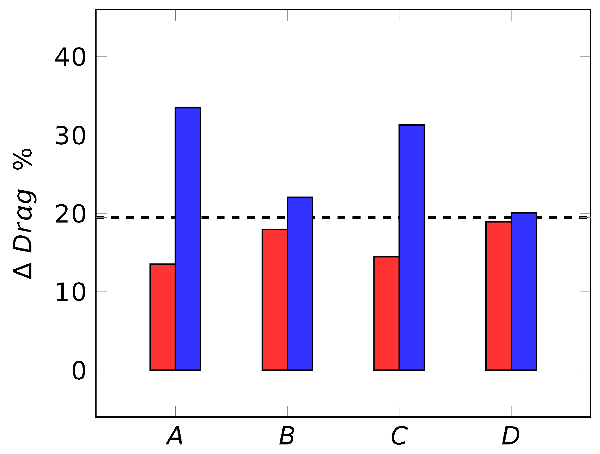
Figure 9 exemplifies the consequences of neglecting these considerations. These are certainly exaggerated by the choice of working with a dimple configuration that causes a large change of drag. However, the relative differences are major; neglecting such considerations would most certainly hinder the true ability of dimples to alter skin-friction drag.
5.4. The Drag Reduction Metrics
In closing, we mention a final methodological issue that affects drag reduction measurements for dimples, riblets and roughness at large: the proper metrics to express it. It is customary to express drag reduction as percentage changes in the skin-friction coefficient at a given ; unfortunately, the coefficient itself already contains a dependence on the Reynolds number for the flat wall case, thus making it impossible to rely on percentage changes for a robust assessment of the drag change properties of a given surface. The complete information would be the pair. Alternatively, the proper metric for expressing drag reduction is the vertical shift of the logarithmic portion of the mean streamwise velocity profile expressed in viscous units.
This is a known concept for roughness [41] as well as riblets [42,43] and also extends to some active flow control strategies [44]. As long as the direct effect of the roughness remains confined within the buffer layer of the turbulent flow, it can be translated into an upward shift of the logarithmic velocity profile in the law of the wall: a positive corresponds to drag reduction, and a negative implies drag increase, as for the conventional k-type roughness. Part of the trends seen in Figure 6 for drag reduction data are due to Reynolds effects; properly removing them via analytical relations is possible, as accomplished in ref. [44] for active spanwise forcing and would contribute to clarifying the situation by exposing some remaining “puzzling” trends with (to cite words used in ref. [23]).
6. Conclusions
In this review paper, we have provided a brief and up-to-date description of what we know and what we do not about the potential of dimples for turbulent skin-friction drag reduction. While we cannot obviously offer an answer to the still-standing question of whether or not dimples are a suitable technique to reduce turbulent skin-friction drag, it is our hope that this comprehensive overview will at least help the newcomer frame the problem, quickly identify the key references and get a glimpse at the complexity of the topic.
While reviewing the state of the art, we have also mentioned some methodological issues that bear a critical importance when attempting to measure drag changes by dimples. Leveraging concepts and procedures (and perhaps facilities altogether) developed over the years for riblets might yield data that are reliable enough to begin understanding the physics behind dimple drag reduction, a necessary and preliminary step to improve their performance.
Author Contributions
F.G., A.C. and M.Q. contributed equally to conceptualization, investigation, methodology, and writing. All authors have read and agreed to the published version of the manuscript.
Funding
This research received no external funding.
Institutional Review Board Statement
Not applicable.
Informed Consent Statement
Not applicable.
Data Availability Statement
The data presented in this study are available on request from the corresponding author.
Conflicts of Interest
The authors declare no conflict of interest.
Appendix A. Computational Details
In this review, we have also presented results from DNS simulations carried out for the present work. They concern a turbulent plane channel flow with dimples placed on one wall only. The employed parallel DNS code was introduced by [45], and solves the incompressible Navier–Stokes equations in primitive variables on a staggered Cartesian grid. Space discretization is based on second-order finite differences, and temporal integration uses a fractional time-stepping method based on a third-order Runge–Kutta scheme. The Poisson equation for the pressure is solved by an iterative successive over-relaxation algorithm. An implicit immersed-boundary method, implemented in staggered variables, continuous with respect to boundary crossing and numerically stable at all distances from the boundary [45,46] describes the geometry of the non-planar wall. Periodic boundary conditions are enforced in both the streamwise and spanwise directions, while no slip and no penetration boundary conditions are enforced at the walls.
The size of the computational domain (and therefore the number of dimples considered) is chosen to ensure that it is always larger than the minimal flow units needed to sustain the near-wall turbulence cycle [47]. The smallest domain in our simulations has size and in external units and and in viscous units. A uniform distribution of points is used in both the streamwise and spanwise directions, with the selected grid spacing ensuring that and for all the considered cases. In the wall-normal direction, a non-uniform distribution is used to properly resolve the dimples and the near wall region. The grid spacing is indeed constant from the dimple bottom to the dimple tip from where a hyperbolic tangent distribution is used. The number of points in the wall-normal direction is chosen to ensure that at the walls for all cases. The number of points for the simulations in Figure 9, carried out at about (or ) is , and . For the simulations in Figure 7, instead, the number of points increases up to , and to deal with the higher Reynolds numbers, since in this dataset the Reynolds number varies, in the range (or ).
References
- García-Mayoral, R.; Jiménez, J. Drag Reduction by Riblets. Phil. Trans. R. Soc. A 2011, 369, 1412–1427. [Google Scholar] [CrossRef] [PubMed] [Green Version]
- Quadrio, M.; Chiarini, A.; Banchetti, J.; Gatti, D.; Memmolo, A.; Pirozzoli, S. Drag Reduction on a Transonic Airfoil. J. Fluid. Mech. 2022, 942, 1–10. [Google Scholar] [CrossRef]
- Cacciatori, L.; Brignoli, C.; Mele, B.; Gattere, F.; Monti, C.; Quadrio, M. Drag Reduction by Riblets on a Commercial UAV. Appl. Sci. 2022, 12, 5070. [Google Scholar] [CrossRef]
- McLean, J.; George-Falvy, D.; Sullivan, P. Flight Test of Turbulent Skin-Friction Reduction by Riblets. In Proceedings of the International Conference on Turbulent Drag Reduction by Passive Means, London, UK, 15–17 September 1987; Volume RAeS 2, pp. 408–424. [Google Scholar]
- Kurita, M.; Iijima, H.; Koga, S.; Nishizawa, A.; Kwak, D.; Iijima, Y.; Takahashi, H.; Abe, H. Flight Test for Paint Riblets. In AIAA Scitech 2020 Forum; American Institute of Aeronautics and Astronautics: Reston, VA, USA, 2020. [Google Scholar]
- Leontiev, A.; Kiselev, N.; Vinogradov, Y.; Strongin, M.; Zditovets, A.; Burtsev, S. Experimental Investigation of Heat Transfer and Drag on Surfaces Coated with Dimples of Different Shape. Int. J. Therm. Sci. 2017, 118, 152–167. [Google Scholar] [CrossRef]
- Choi, J.; Jeon, W.P.; Choi, H. Mechanism of Drag Reduction by Dimples on a Sphere. Phys. Fluids 2006, 18, 41702. [Google Scholar] [CrossRef] [Green Version]
- Allarton, R.; Yao, J.; Clifford, T.; Hitchborn, B.; Parker, L.; Shaw, J. Surface Flow Modification of Aerofoils for Automotive Racing Car Applications. Int. J. Mod. Phys. 2020, 34, 2040096. [Google Scholar] [CrossRef]
- Ge, M.W.; Fang, L.; Liu, Y.Q. Drag Reduction of Wall Bounded Incompressible Turbulent Flow Based on Active Dimples/Pimples. J. Hydrodyn. 2017, 29, 261–271. [Google Scholar] [CrossRef]
- Kiknadze, G.I.; Krasnov, Y.K.; Chushkin, Y.V. Investigation of the Enhancement of Heat Transfer Due to Self-Organization of Ordered Dynamic Twisted Heat-Carrier Structures on a Heat-Transfer Surface; Technical Report 50.05/59; I. V. Kurchatov Institute of Atomic Energy: Moscow, Russia, 1984. [Google Scholar]
- Alekseev, V.V.; Gachechiladze, I.A.; Kiknadze, G.I.; Oleinikov, V. Tornado-like Energy Transfer on Three-Dimensional Concavities of Reliefs-Structures of Self Organizing Flow, Their Visualisation, and Surface Streamlining Mechanism. Heat Transf. Intensif. Radiat. Complex Heat Transf. 1998, 6, 33–42. [Google Scholar]
- Chen, Y.; Chew, Y.T.; Khoo, B.C. Enhancement of Heat Transfer in Turbulent Channel Flow over Dimpled Surface. Int. J. Heat Mass Transf. 2012, 55, 8100–8121. [Google Scholar] [CrossRef]
- Praß, J.; Wannmacher, H.; Franke, J.; Becker, S. The Influence of Different Arrangements of Shallow Dimples on the Resistance of Plates Subjected to Relative Fluid Motion. Tech. Mech. 2019, 39, 39–50. [Google Scholar]
- Tay, C.M.J.; Khoo, B.C.; Chew, Y.T. Use of DES in Mildly Separated Internal Flow: Dimples in a Turbulent Channel. J. Turbul. 2017, 18, 1180–1203. [Google Scholar] [CrossRef]
- Ng, J.; Jaiman, R.; Lim, T.; Tay, C.; Khoo, B. Geometric Effects of Shallow Dimples in Turbulent Channel Flows at Reτ≈ 180: A Vorticity Transport Perspective. Flow Turbul. Combust. 2020, 105, 83–122. [Google Scholar] [CrossRef]
- Veldhuis, L.; Vervoort, E. Drag Effect of a Dented Surface in a Turbulent Flow. In Proceedings of the 27th AIAA Applied Aerodynamics Conference, San Antonio, TX, USA, 22–25 June 2009; p. 3950. [Google Scholar]
- Tay, C. Determining the Effect of Dimples on Drag in a Turbulent Channel Flow. In Proceedings of the 49th AIAA Aerospace Sciences Meeting Including the New Horizons Forum and Aerospace Exposition, Orlando, FL, USA, 4–7 January 2011; p. 682. [Google Scholar]
- Tay, C.; Khoo, B.; Chew, Y. Mechanics of Drag Reduction by Shallow Dimples in Channel Flow. Phys. Fluids 2015, 27, 035109. [Google Scholar] [CrossRef]
- Van Nesselrooij, M.; Veldhuis, L.; Van Oudheusden, B.; Schrijer, F. Drag Reduction by Means of Dimpled Surfaces in Turbulent Boundary Layers. Exp. Fluids 2016, 57, 142. [Google Scholar] [CrossRef]
- Tay, C.; Lim, T.; Khoo, B.; Jaiman, R. Effectiveness of Triangular Depressions and Asymmetric Circular Dimples for Drag Reduction. In Proceedings of the 20th Australasian Fluid Mechanics Conference, Perth, Australia, 5–8 December 2016. [Google Scholar]
- Tay, J.; Lim, T.T. Drag Reduction with Non-Axisymmetric Dimples. In Proceedings of the 35th AIAA Applied Aerodynamics Conference, Denver, CO, USA, 5–9 June 2017; p. 3569. [Google Scholar]
- Tay, J.; Lim, T.T. Drag Reduction with Teardrop-Shaped Dimples. In Proceedings of the 2018 Flow Control Conference, Atlanta, GA, USA, 25–29 June 2018; p. 3528. [Google Scholar]
- Spalart, P.; Shur, M.; Strelets, M.; Travin, A.; Paschal, K.; Wilkinson, S. Experimental and Numerical Study of the Turbulent Boundary Layer over Shallow Dimples. Int. J. Heat Fluid Flow 2019, 78, 108438. [Google Scholar] [CrossRef]
- Van Campenhout, O.; Van Nesselrooij, M.; Veldhuis, L.L.; Van Oudheusden, B.; Schrijer, F. An Experimental Investigation into the Flow Mechanics of Dimpled Surfaces in Turbulent Boundary Layers. In Proceedings of the 2018 AIAA Aerospace Sciences Meeting, Kissimmee, FL, USA, 8–12 January 2018; p. 2062. [Google Scholar]
- Dean, R. Reynolds Number Dependence of Skin Friction and Other Bulk Flow Variables in Two-Dimensional Rectangular Duct Flow. Trans. ASME J. Fluids Eng. 1978, 100, 215–223. [Google Scholar] [CrossRef]
- Lienhart, H.; Breuer, M.; Köksoy, C. Drag Reduction by Dimples?—A Complementary Experimental/Numerical Investigation. Int. J. Heat Fluid Flow 2008, 29, 783–791. [Google Scholar] [CrossRef]
- Tay, J.; Lim, T.T.; Khoo, B.C. Drag Reduction with Diamond-Shaped Dimples. In Proceedings of the AIAA Aviation 2019 Forum, Dallas, TX, USA, 17–21 June 2019; p. 3296. [Google Scholar]
- Kovalenko, G.; Terekhov, V.; Khalatov, A. Flow Regimes in a Single Dimple on the Channel Surface. J. Appl. Mech. Tech. Phys. 2010, 51, 839–848. [Google Scholar] [CrossRef]
- Tay, C.; Chew, Y.; Khoo, B.; Zhao, J. Development of Flow Structures over Dimples. Exp. Therm. Fluid Sci. 2014, 52, 278–287. [Google Scholar] [CrossRef]
- Ng, J.; Jaiman, R.; Lim, T. A Numerical Study for Passive Turbulent Drag Reduction via Shallow Dimples. In Proceedings of the 21st Australasian Fluid Mechanics Conference, Adelaide, Australia, 10–13 December 2018. [Google Scholar]
- Lashkov, Y.A.; Samoilova, N. On the Viscous Drag of a Plate with Spherical Recesses. Fluid Dyn. 2002, 37, 231–236. [Google Scholar] [CrossRef]
- Kiknadze, G.; Gachechiladze, I.; Barnaveli, T. The Mechanisms of the Phenomenon of Tornado-Like Jets Self-Organization in the Flow Along the Dimples on the Initially Flat Surface. In Proceedings of the ASME International Mechanical Engineering Congress and Exposition, Houston, TX, USA, 9–15 November 2012; Volume 7. [Google Scholar]
- Jung, W.; Mangiavacchi, N.; Akhavan, R. Suppression of Turbulence in Wall-Bounded Flows by High-Frequency Spanwise Oscillations. Phys. Fluids A 1992, 4, 1605–1607. [Google Scholar] [CrossRef] [Green Version]
- Quadrio, M.; Ricco, P. Critical Assessment of Turbulent Drag Reduction through Spanwise Wall Oscillation. J. Fluid Mech. 2004, 521, 251–271. [Google Scholar] [CrossRef] [Green Version]
- Quadrio, M.; Sibilla, S. Numerical Simulation of Turbulent Flow in a Pipe Oscillating around Its Axis. J. Fluid Mech. 2000, 424, 217–241. [Google Scholar] [CrossRef] [Green Version]
- Viotti, C.; Quadrio, M.; Luchini, P. Streamwise Oscillation of Spanwise Velocity at the Wall of a Channel for Turbulent Drag Reduction. Phys. Fluids 2009, 21, 115109. [Google Scholar] [CrossRef]
- Van Nesselrooij, M.; Van Campenhout, O.; Van Oudheusden, B.; Schrijer, F.; Veldhuis, L. Development of an Experimental Apparatus for Flat Plate Drag Measurements and Considerations for Such Measurements. Meas. Sci. Technol. 2022, 33, 055303. [Google Scholar] [CrossRef]
- Gatti, D.; Güttler, A.; Frohnapfel, B.; Tropea, C. Experimental Assessment of Spanwise-Oscillating Dielectric Electroactive Surfaces for Turbulent Drag Reduction in an Air Channel Flow. Exp. Fluids 2015, 56, 1–15. [Google Scholar] [CrossRef]
- Bechert, D.W.; Hoppe, G.; Van Der Hoeven, J.G.T.; Makris, R. The Berlin Oil Channel for Drag Reduction Research. Exp. Fluids 1992, 12, 251–260. [Google Scholar] [CrossRef]
- Hasegawa, Y.; Quadrio, M.; Frohnapfel, B. Numerical Simulation of Turbulent Duct Flows at Constant Power Input. J. Fluid Mech. 2014, 750, 191–209. [Google Scholar] [CrossRef] [Green Version]
- Jiménez, J. Turbulent Flows Over Rough Wall. Annu. Rev. Fluid Mech 2004, 36, 173–196. [Google Scholar] [CrossRef]
- Luchini, P. Reducing the Turbulent Skin Friction. In Computational Methods in Applied Sciences 1996; Knoerzer, D., Periaux, J., Tuovinen, T., Eds.; Wiley: Hoboken, NJ, USA, 1996. [Google Scholar]
- Spalart, P.; McLean, J. Drag Reduction: Enticing Turbulence, and Then an Industry. Phil. Trans. R. Soc. A 2011, 369, 1556–1569. [Google Scholar] [CrossRef] [Green Version]
- Gatti, D.; Quadrio, M. Reynolds-Number Dependence of Turbulent Skin-Friction Drag Reduction Induced by Spanwise Forcing. J. Fluid Mech. 2016, 802, 553–558. [Google Scholar] [CrossRef] [Green Version]
- Luchini, P. Immersed-Boundary Simulation of Turbulent Flow Past a Sinusoidally Undulated River Bottom. Eur. J. Mech. B/Fluids 2016, 55, 340–347. [Google Scholar] [CrossRef]
- Luchini, P. Linearized No-Slip Boundary Conditions at a Rough Surface. J. Fluid Mech. 2013, 737, 349–367. [Google Scholar] [CrossRef] [Green Version]
- Jiménez, J.; Moin, P. The Minimal Flow Unit in Near-Wall Turbulence. J. Fluid Mech. 1991, 225, 213–240. [Google Scholar] [CrossRef] [Green Version]
Figure 1.
Cross section of the parametric dimple geometry (left) and streamwise shift of the deepest point (right).
Figure 1.
Cross section of the parametric dimple geometry (left) and streamwise shift of the deepest point (right).
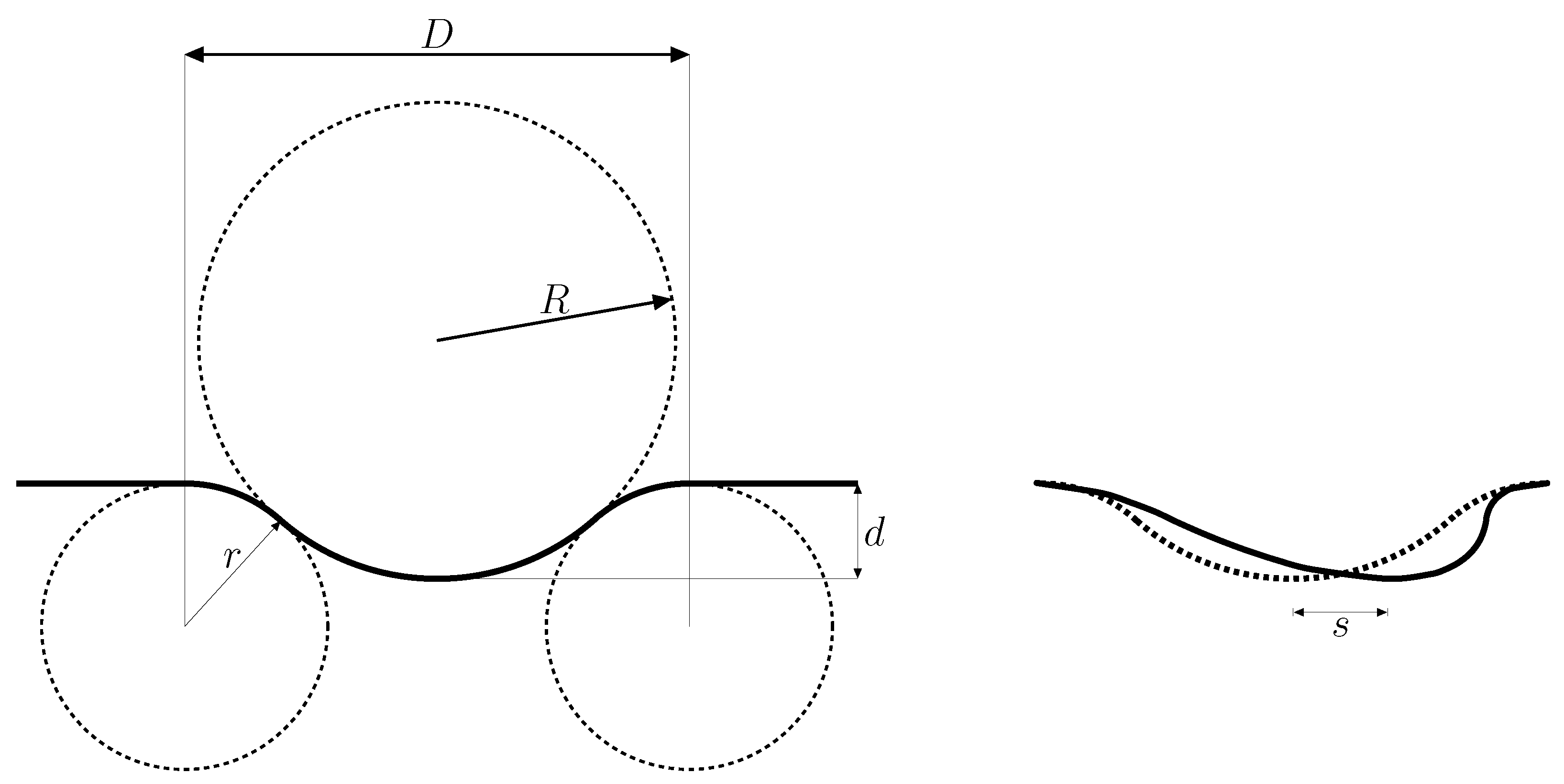
Figure 2.
Popular variants of the dimple shape.

Figure 3.
Most popular dimples layout: staggered (left) and flow aligned (right).
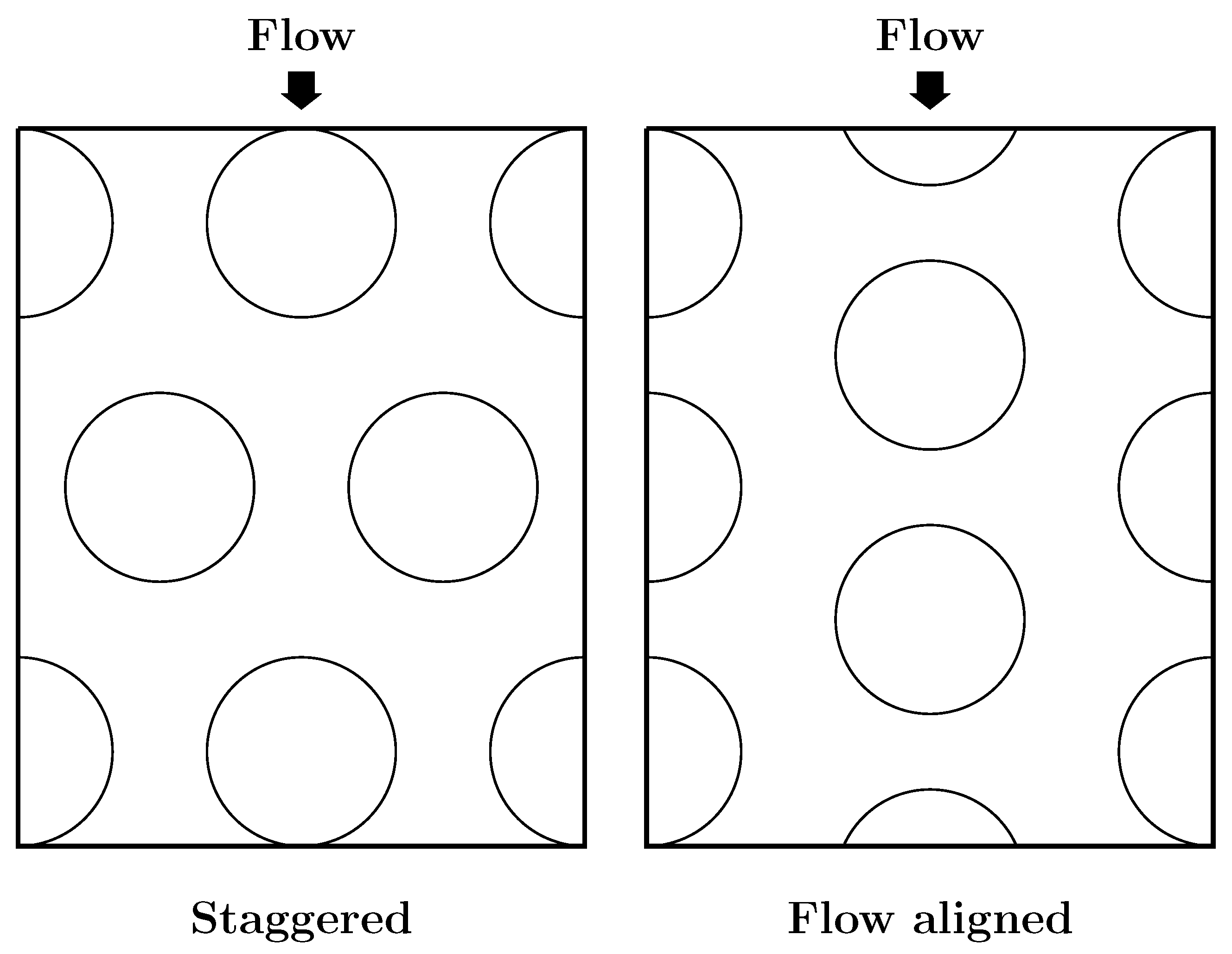
Figure 5.
Instantaneous spanwise velocity component w on a wall-parallel plane at from the flat part of the wall. Lengths and velocities are made dimensionless with h and . The velocity field is computed by DNS for a circular dimple, which actually yields a drag increase.
Figure 5.
Instantaneous spanwise velocity component w on a wall-parallel plane at from the flat part of the wall. Lengths and velocities are made dimensionless with h and . The velocity field is computed by DNS for a circular dimple, which actually yields a drag increase.
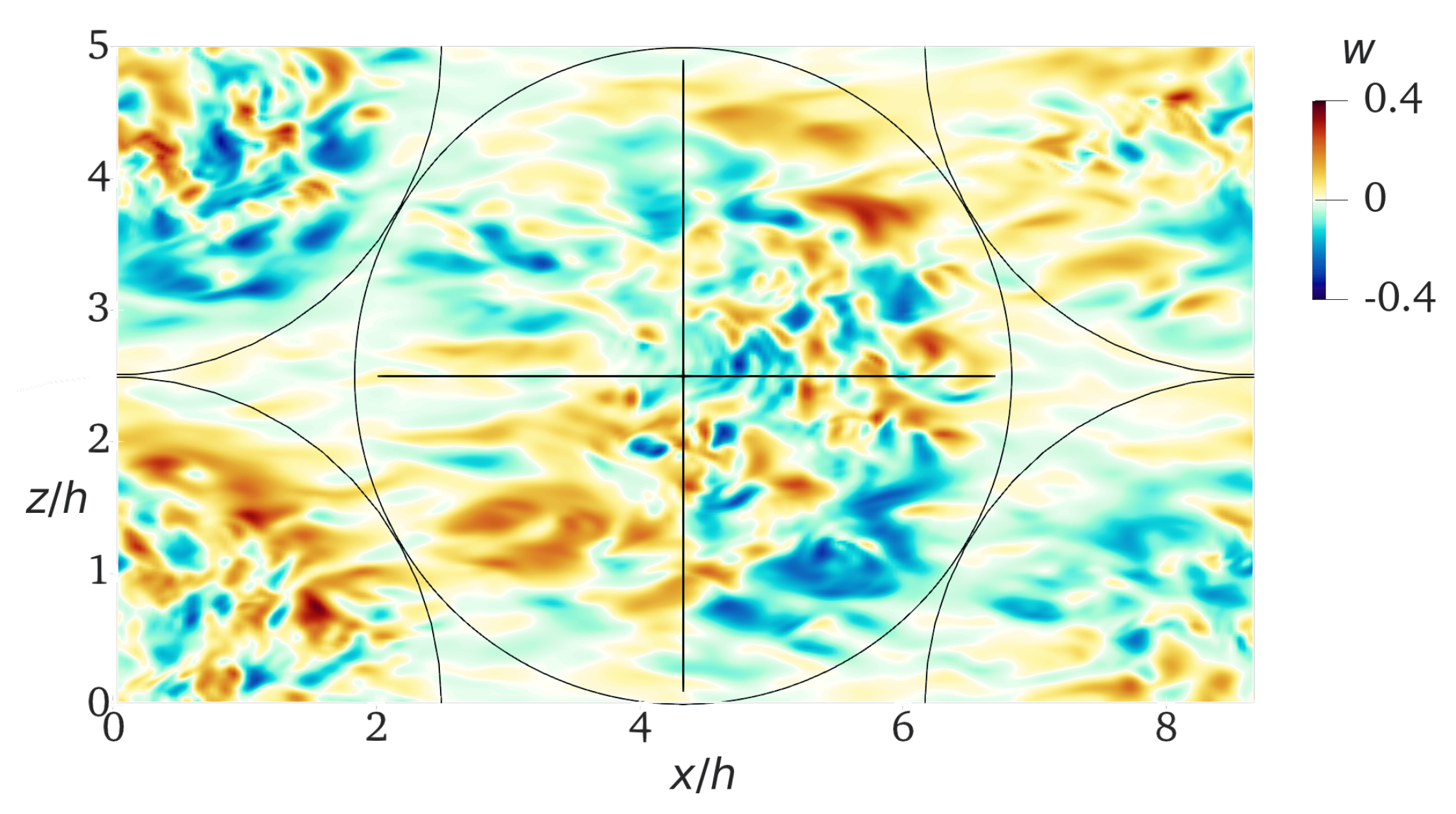

Figure 7.
Present simulations, circular dimples at various sizes and Reynolds numbers with . Left: drag changes vs. dimple depth in inner units. Right: drag changes vs. dimple depth in outer units.
Figure 7.
Present simulations, circular dimples at various sizes and Reynolds numbers with . Left: drag changes vs. dimple depth in inner units. Right: drag changes vs. dimple depth in outer units.
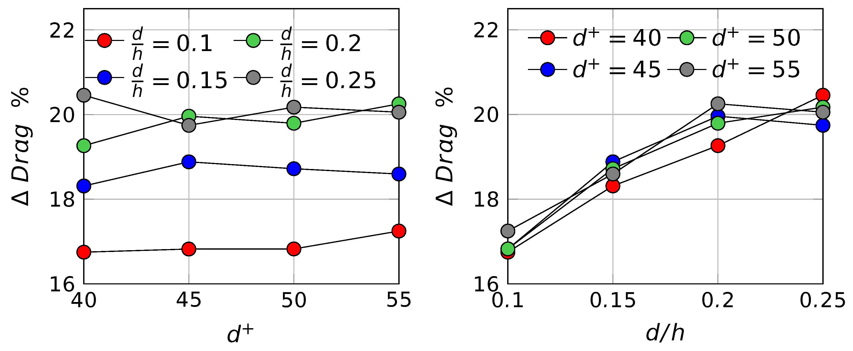
Figure 8.
A dimpled wall and two different, equivalent flat channels. The red/blue lines indicate the dimple profile. Left: the channel height goes from the top wall to the dimple tip; right: the channel height goes from the top wall to the dimple lowest point.
Figure 8.
A dimpled wall and two different, equivalent flat channels. The red/blue lines indicate the dimple profile. Left: the channel height goes from the top wall to the dimple tip; right: the channel height goes from the top wall to the dimple lowest point.

Figure 9.
Drag changes, measured by DNS, for circular dimples with at . Red/blue bars express drag changes when the equivalent channel defines as the distance between the top wall and the top/bottom of the dimple (color code is the same of Figure 8). Case A: comparison at the same , computed without accounting for the volume ratio. Case B: as case A, but is corrected with the volume ratio. Cases C and D are like cases A and B, but the comparison is made at the same flow rate.

Table 1.
Summary of the main parameters and results of the literature. Columns report, in sequential order: 1. the reference and its acronym; 2. the numerical (DNS: direct numerical simulation, LES: large eddy simulation, DES: detached eddy simulation, FVM: finite volume method, SEM: spectral element method) or experimental approach; 3. the flow type: channel flow (CF), half-channel flow (HCF) or boundary layer (BL); 4. the value of the Reynolds number: for CF and HCF, for BL (other definitions for CF are converted to using Dean’s law); 5. the dimple shape: circular (Circ), triangular (Triang), diamond (Diam), elliptical (Ell), teardrop (Tear), upstream-pointing (Up), Downstream-pointing (Do); 6. spanwise width and streamwise length , expressed as a fraction of the reference length L (the channel half-height h for CF and the boundary layer thickness for BL), for a circular dimple , thus only one value is reported; 7. the dimple depth d; 8. the edge curvature radius r; 9. the curvature radius R of the spherical cap; 10. the shift s of the point of maximum depth; 11. the coverage ratio; 12. the type of layout: S: staggered, A: aligned, H: hexagonal; 13. the percentage drag change. “-” is used when some information required to compute the value is lacking.
| Article | Num/Exp | Flow | Re | Shape | Cov% | Layout | ||||||
|---|---|---|---|---|---|---|---|---|---|---|---|---|
| LBK-08 [26] | Exp | CF | ≈10,000 | Circ | 5 | - | - | 0 | A | 0 | ||
| DNS (FVM) | CF | Circ | 5 | - | - | 0 | A | |||||
| VV-09 [16] | Exp | BL | - | Circ | - | 5 | - | - | 0 | 60 | S | |
| T-11 [17] | Exp | CF | ≈17,500 | Circ | 5 | 5 | 0 | 90 | S | |||
| TKC-15 [18] | Exp | CF | ≈32,100 | Circ | 5 | 5 | 0 | 90 | S | |||
| VVVS-16 [19] | Exp | BL | ≈1500 | Circ | 0 | S | ||||||
| TLKJ-16 [20] | Exp | CF | ≈5625 | Triang Up | 5 | - | - | - | S | |||
| Exp | CF | ≈5625 | Triang Do | 5 | - | - | - | S | ||||
| Exp | CF | ≈50,350 | Circ | 5 | 5 | - | - | 90 | S | |||
| TKC-17 [14] | DES (FVM) | CF | ≈2830 | Circ | 5 | 0 | 90 | S | ||||
| TL-17 [21] | Exp | CF | ≈28,600 | Circ | 5 | - | - | 90 | S | |||
| TL-18 [22] | Exp | CF | ≈42,850 | Circ | 5 | 5 | - | - | 0 | - | S | |
| Exp | CF | ≈30,140 | Tear Up | 5 | - | - | 84 | S | ||||
| Exp | CF | ≈22,270 | Tear Dp | 5 | - | - | 84 | S | ||||
| VVVVS-18 [24] | Exp | BL | - | Circ | - | - | 0 | - | S/A/H | |||
| SSSTPW-19 [23] | DNS (FVM) | BL | 30,000 | Circ | - | - | 0 | - | S | |||
| TLK-19 [27] | Exp | CF | ≈30,000 | Diam | 5 | - | - | 0 | 99 | S | ||
| PWFB-19 [13] | LES (FVM) | HCF | ≈6121 | Circ | 0 | - | S | |||||
| NJLTK-20 [15] | DNS (SEM) | CF | 2800 | Circ | 5 | 5 | S | |||||
| DNS (SEM) | CF | 2800 | Ell | 5 | 0 | S | ||||||
| DNS (SEM) | CF | 2800 | Tear Up | 5 | S | |||||||
| DNS (SEM) | CF | 2800 | Tear Dp | 5 | S | |||||||
| DNS (SEM) | CF | 2800 | Diam | 5 | 0 | S |
Publisher’s Note: MDPI stays neutral with regard to jurisdictional claims in published maps and institutional affiliations. |
© 2022 by the authors. Licensee MDPI, Basel, Switzerland. This article is an open access article distributed under the terms and conditions of the Creative Commons Attribution (CC BY) license (https://creativecommons.org/licenses/by/4.0/).
Share and Cite
MDPI and ACS Style
Gattere, F.; Chiarini, A.; Quadrio, M. Dimples for Skin-Friction Drag Reduction: Status and Perspectives. Fluids 2022, 7, 240. https://doi.org/10.3390/fluids7070240
AMA Style
Gattere F, Chiarini A, Quadrio M. Dimples for Skin-Friction Drag Reduction: Status and Perspectives. Fluids. 2022; 7(7):240. https://doi.org/10.3390/fluids7070240
Chicago/Turabian StyleGattere, Federica, Alessandro Chiarini, and Maurizio Quadrio. 2022. "Dimples for Skin-Friction Drag Reduction: Status and Perspectives" Fluids 7, no. 7: 240. https://doi.org/10.3390/fluids7070240