
A Detailed Numerical Study on Aerodynamic Interactions of Tandem Wheels on a Generic Vehicle

School of Engineering, Macquarie University, Sydney, NSW 2109, Australia
*
Author to whom correspondence should be addressed.
Fluids 2023, 8(10), 281; https://doi.org/10.3390/fluids8100281
Submission received: 29 June 2023
/
Revised: 21 September 2023
/
Accepted: 16 October 2023
/
Published: 20 October 2023
(This article belongs to the Special Issue Aerodynamics and Aeroacoustics of Vehicles, 3rd Edition)
Abstract
:Wheels contribute significantly to the aerodynamic performance of ground vehicles. Many studies have focused on investigating a single wheel either in isolation or in a wheelhouse. However, there has been less focus on the flow field around a rear wheel, especially when considering varying proximity to the front wheel, despite its importance on aerodynamic forces. In this study, a generic reference body is modified and fitted with a rear wheel within a wheelhouse and analysed while the wheel spacing varies. Reynolds-Averaged Navier–Stokes (RANS) modelling was employed to allow for multiple variations to be considered and the model produced results in good agreement with experimental results. The results confirm that two upper rear wheelhouse outflow vortices are only present when the wheel spacing is short. It was found that the drag values were minimal for the wheel spacing at a critical distance of 1.5 wheel diameters. At this wheel spacing, the formation of the outboard jetting vortex is prevented at the rear wheel, and hence, the rear wheel drag is reduced by more than 10%. Any further reduction in the spacing does not provide any drag benefits. Also, the outflow from the front wheelhouse is projected further away from the body, drawing flow from the rear wheelhouse into the outboard jetting vortex.
1. Introduction
The aerodynamics of wheels is a significant factor in designing road vehicles. Drag becomes the most resistive force at speeds greater than 50 km/h, having a direct impact on vehicle emissions and fuel economy [1,2]. In recent years, the electrification of the automotive sector has surged in popularity, and hence, methods of effective drag reduction are becoming even more important to increase vehicle ranges [3]. This development has been reported to be one of the most important design criteria for modern electrical vehicles (EVs), which have some of the lowest drag coefficients for passenger vehicles in the history of the automotive industry [1].
Wheels have been shown to contribute up to 30% of vehicle drag [4,5,6,7,8], and the effect of wheel aerodynamics has received significant attention in the prior literature. The analysis of isolated wheels has provided an understanding of the flow structures generated by wheel rotation and contact with the moving ground. Analysis has reported on the upper shoulder vortices and jetting vortices from the contact patch [9,10,11,12], which are generated by the oncoming flow reaching the contact region between the wheel and ground. As the flow cannot pass through the contact patch in the case of a slick tyre [9,10,11], static pressure increases rapidly and projects the flow spanwise around the wheel to form the jetting vortices. Studies by Cogotti [10] and Axon [12] demonstrated the importance of the rotating tyre and contact patch modelling to accurately depict the flow field around the wheel and the relevant forces. Inadequate modelling or inadequate representation of this wheel–ground contact region can influence the description of forces acting on the wheel [10,13]. Previous studies [7,14] have lowered the wheel into the ground plane in order to represent the contact patch, but it generally results in a lack of contact resolution. Furthermore, once the wheel is placed within a wheelhouse, the jetting vortices are no longer symmetrical, and the shoulder vortices do not form as the outflow from the wheelhouse becomes the dominant flow [7,12,15,16,17,18].
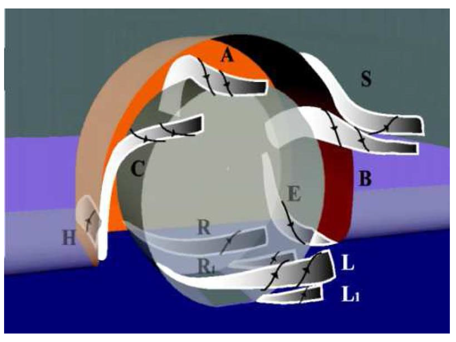
Figure 1 schematically shows the key vortices which have been reported to form about a wheel within a wheelhouse [7,14,18,19]. Vortex H is formed as the flow from the underbody separates from the front lower leading edge of the wheelhouse and rolls up into the cavity. This vortex is sensitive to the inflow yaw angle, which varies with changes in the body’s front overhang [14]. Vortices A and B have been identified as extensions of vortex H as flow towards the inner wheelhouse [20]. The formation and increased strength of vortex B for shorter front overhang bodies, in turn, affect the formation of vortex S [14]. Vortex C forms as the flow along the side face separates and rolls towards the wheelhouse cavity, remaining outside of the wheelhouse and changing trajectory towards the freestream direction. The primary wheelhouse outflow is driven by vortices A and B, with the remaining outflow carried through vortex E into the underbody [14]. The jetting vortices L and R form as the freestream flow reaches the contact patch, and they are forced tangentially around the wheel. A smaller pair of counter-rotating vortices L1 and R1 form as the flow is lifted from the ground due to vortices L and R [7]. For reference, this vortex naming convention is adopted for this study as it was used in previous studies focusing on the Fabijanic model [7,14,21].
Previous studies showed that variations in wheelhouse radius, depth and front overhang alter the position, size or strength of the vortex formations [7,14,18,19]. It was found that the formation of vortices A and B are dependent on the forebody length, where a longer forebody allows for more flow to roll up through vortex H and contribute to vortex A [14,20]. Shorter forebodies experience a greater yaw angle for the incoming flow, which aids the formation of vortex B [14]. The size of vortex B decreases as the wheelhouse width reduces while a reduction in the wheelhouse diameter decreases the size of vortices H and C [14]. Regert and Lajos [14] also demonstrated that the ratio between the wheel and wheelhouse diameters had a larger effect on the total forces than the width ratio.
To analyse the wheel and wheelhouse flow, previous studies have adopted a variety of bodies and wheelhouse configurations with varying degrees of simplifications [12,18,22,23,24], which aid in developing the general knowledge of the flow field. It is particularly important because the rim shape and wheelhouse geometry may have a unique effect on the vortices generated, also specific vehicle bodies may not produce transferrable results [4,16,23,25,26,27,28]. Among these models, the Fabijanic model has been considered in various studies [7,14,18]. The model represents a simple square-backed body with a radius along the front and side edges, and the wheel is represented by a square-edged cylinder. Significant changes in the flow structures are observed with a greater variation in either wheel or wheelhouse geometries. The height and angle of the front overhang along with varying wheelhouse geometries have been shown to alter the formation of vortices [24,29]. This effect occurs because the stagnation point on the forward face of the wheel is positioned higher on the leading face of the body, hence a larger mass flow of air moves through the underbody.
Studies concerning the effects of wheels on the Ahmed body have been conducted to establish a simplified body with front and rear wheels [15,30,31]. Notable differences between the front and rear wheel flow structures are seen; however, the primary objective of those studies was to investigate the effects of wheels on a generic body. However, there is a lack of knowledge about how the rear wheel flow structures may change with the wheelbase and affect the drag of the whole body. Other studies of more realistic geometries focused on the effects of ground simulation and wheel rotation, focusing on the effect of the flow structures associated with the front wheel [16,25]. Despite valuable findings for simplified geometries, vortices A and B (see Figure 1) have only been identified in studies which utilise simplified geometries, while they did not consider the suspension geometry [7,14]. Nevertheless, there is a need to investigate the rear wheel and wheelhouse flow on a simplified body because the other key wheelhouse vortices (H, C, E, S) are expected to be presented.
Interactions between tandem cylinders have been also investigated in two-dimensional studies [32,33,34,35,36], showing that bodies trailing a leading body experience a drag reduction. Though Spagnolo et al. [37,38] documented the vortex interaction caused by the laminar–turbulent transition of the leading wheel for a landing gear with extremely small wheel spacing, the wheels were exposed to the external flow and not entirely representative of automotive flows. Hence, a brief comparison of vortex structures was conducted for tandem Fackrell wheels for a single wheel spacing of 0.5 d [39].
This study aims, for the first time, to conduct a comprehensive analysis of the effects of tandem wheels within a wheelhouse on a generic body. It mainly focuses on how the changes in wheel spacing affect the flow structures and the drag of the simplified vehicle. For this purpose, the Fabijanic model is modified to include a rear wheel and wheelhouse equal to the front wheel dimensions. Wheel spacing is then varied for a range of wheelbases commonly found on both heavy and passenger vehicles. Given that the aforementioned vortices have been identified for single-wheeled bodies, this study will provide insight into the general vortex formation for both front and rear wheels, thus enhancing the understanding of geometric changes that affect wheel and wheelhouse flow structures.
2. Methodology
2.1. Problem Definition
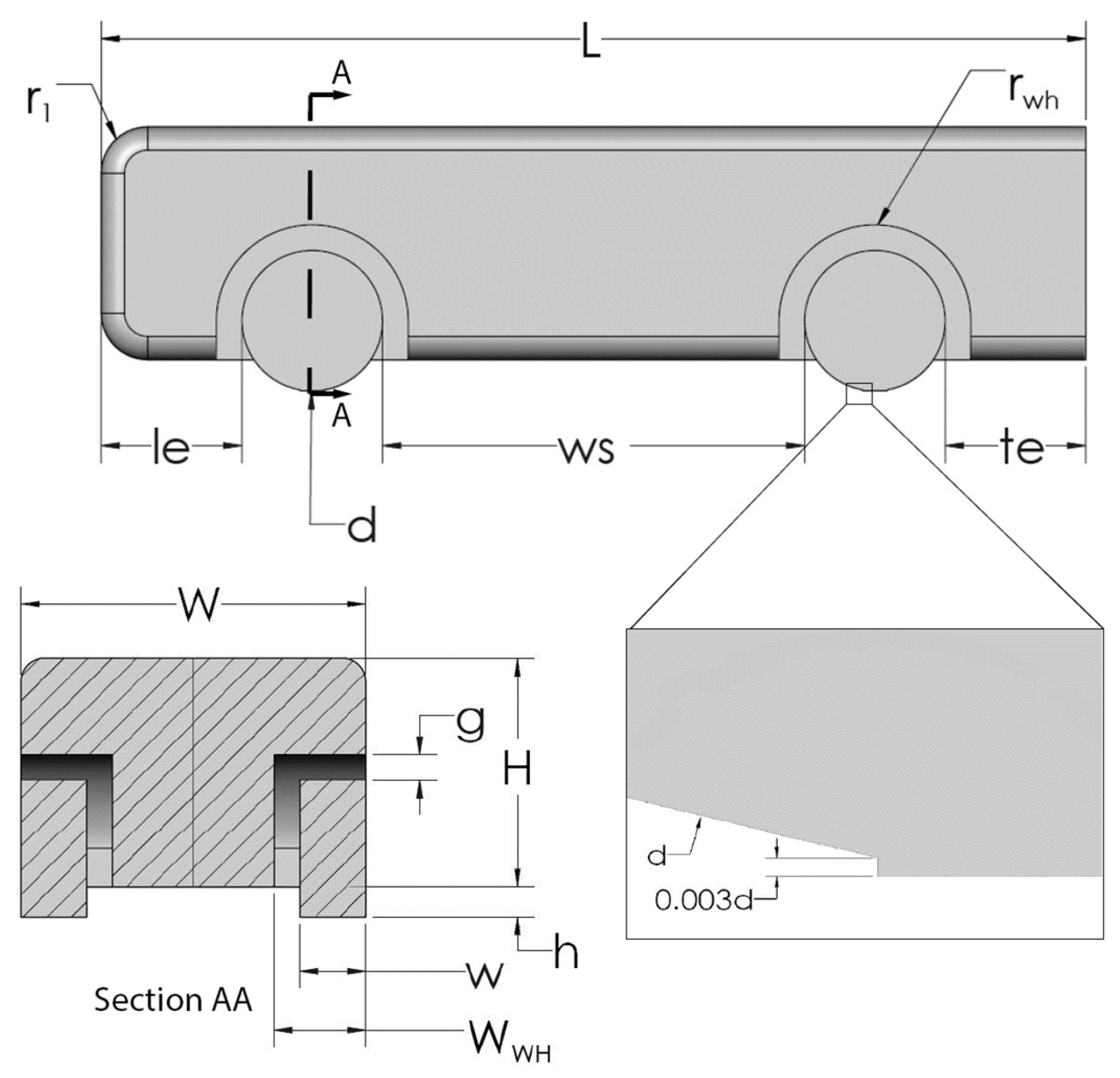
Figure 2 presents schematic views of body configuration and wheels. The modified Fabijanic model in baseline configuration uses a wheel diameter of d = 76.6 mm and wheelhouse radius of rwh = 52.3 mm, which are the same as the original experiment by Fabijanic [18] and consistent with the previous numerical studies [7,14]. The contact patch at the wheel was modelled by trimming the bottom portion of the wheel at a height of 0.003 d [13] and extruding a block towards the ground plane, as shown in Figure 2. In all simulations, the front and rear overhang, shown by le and te, respectively, are constant, equal to the wheel diameter and are measured from the closest tangent plane on the wheel. Baseline wheel spacing (ws) was measured between the two inner tangent planes on each wheel and set at 3 d. Other geometric dimensions including width, body height and edge radii are all in accordance with the original Fabijanic model, which are W = 190.5 mm, H = 127 mm and r1 = 25 mm, respectively. Body dimensions are summarized in Table 1.
Wheel spacing was then varied for each configuration, ranging from 0.5 d to 6 d. Smaller spacings 0.5–1.5 d were intended to represent typical spacing found on multi-axle vehicles such as buses, trucks and trailers. Wheel spacing less than 0.5 d was not tested as the changes to the current geometry would result in a single wheelhouse for both wheels. Buses and other long wheelbase vehicles are represented by spacings greater than 4 d, while typical passenger cars fall between 2.5 and 3.5 d. As noted, front and rear overhang remained constant to isolate the effects of wheel spacing on the body, while body length varies with the changes in wheel spacing. Modified dimensions for L and ws are provided in Table 2.
2.2. Numerical Model
The simulations are based on the Reynolds-Averaged Navier–Stokes (RANS) method with a turbulence closure model. The time averaged equations are provided in Cartesian tensor form:
where and are the density and viscosity, respectively. is the mean velocity, and it is resulted from decomposing the instantaneous velocity u, into mean and fluctuating () components:
The two-equation models resolve turbulent production and dissipation within the flowfield, and they are calculated using the turbulence intensity and hydraulic diameter prescribed at the inlet. Both realizable k-ε (RKE) [40] and k-ω SST [41] models were considered for the study as they have been used extensively in previous studies concerning wheels, particularly the RKE model due to its capability to resolve rotating shear flow [40]. Turbulent production (k) and dissipation () for the RKE model are defined by Equations (4) and (5). Coefficient is set to 0.09.
Further details on turbulence model selection are provided in the Validation.
2.3. Case Set-Up
The computational domain is shown in Figure 3. Inlet and outlet distance are determined by x1 = 8(H + h) and x2 = 21(H + h), which was sufficient from previous studies of similar geometries [7,42,43], height (Z) and width (Y), are set to 750 mm [7,18] and 500 mm, respectively. The domain height matches the original experiment by Fabijanic [18], while the width was increased to avoid mesh stability complications. In addition, the extended width benefitted the model by reducing effects from the far field walls resulting in a blockage ratio of 3.39%. Smaller blockage ratios of 1.93% and 0.83% were tested and results showed negligible changes in body forces and residual trends. A slip condition was applied to the far-field walls to prevent boundary layer growth. A symmetry condition was employed as only the left half of the modified Fabijanic model was considered in this study. The inlet velocity was set to 30 m/s in line with previous studies [7,14,18], resulting in a Reynolds number of based on body length. A turbulence intensity of 0.35% and a length scale of 42 mm calculated using Equation (6) were considered for all simulations. Linear velocity was applied to the ground plane and rotational boundary condition with a rotational velocity of 783 rad/s at the wheels so that the tangential velocity at the outermost surface of the wheels matches the ground velocity. Wheel rotation was represented by rotating walls and no-slip conditions were applied to the rest of the body.
As shown in Figure 4, a cartesian grid with wedge elements was generated to join the prism layers to the rest of the domain. Forces were monitored on the front and rear wheels, and wheelhouses to identify the contribution that each region made on the overall aerodynamic loads. Each face on the body was monitored individually but presented as a single body force, shown as the green surface in Figure 4, in this study. A minimum edge length of was applied at the contact patch and used for the first prism layer, resulting in a global . Mesh refinement was applied around the contact patch, wheels and in the wake region behind the body, to ensure the significant flow structures associated with predicting drag were captured. As the study focuses on the flow structures of the wheels, further mesh refinement was applied around wheels and contact patch regions. The sizing applied to the bodies of influence around the wheels and contact patch allowed for a 30–40% transition in volume between the prism and cartesian grids. The mesh proved to be stable during the solution process with maximum skewness and an inverse orthogonal quality below 0.98. Following a rigorous mesh verification study, a mesh count for the baseline model consisted of 17.5 million elements, producing force results that changed by no more than 0.5%.
The coupled scheme was employed for the pressure–velocity coupling as it produced a converged solution in less wall-clock time over the SIMPLE and SIMPLEC schemes. Residuals were monitored until periodicity was reached, which occurred with a target error of . Convergence was determined once the residuals and force monitors had reached a steady state, with force coefficients calculated across three oscillations with no more than 0.1% variance from the mean value.
3. Results
3.1. Grid Verification
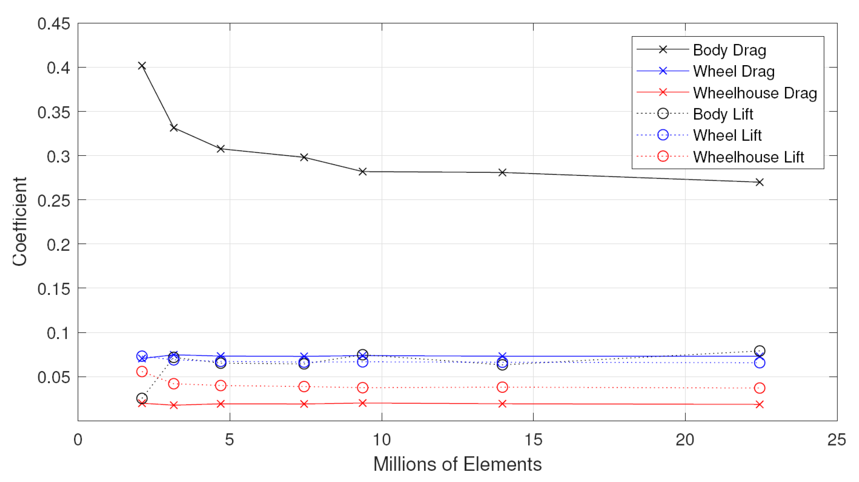
A grid verification study for the validation case was performed to determine the appropriate grid size and it is presented in Figure 5. Minimum variation was observed for the selected grid size of 9.8 × 10⁶ elements (minimum edge length = 0.0275 mm) with a periodic oscillation that did not exceed 0.2% for the monitored forces and turbulence quantities. No significant increase in solution accuracy was observed beyond this grid sizing. A five-element buffer layer surrounded each respective grid size to prevent any sudden grid spacing variations. The Grid Convergence Index was also compared against the exact solution using Richardson’s Extrapolation [44]. Wheel forces yielded errors below 6%, which can be assumed to be within the asymptotic region [44].
3.2. Validation
The wheelhouse–wheel diameter ratio of 1.37 was considered for the cases in this study. However, to validate the model, the simulations were conducted for two more ratios of 1.14 and 1.6, where the wheel diameter remains d = 76.6 mm, thus replicating the experimental investigation conducted by Fabijnaic [18]. The simulations for the equivalent body without wheels (referred to as a basic body [18]) were also conducted to obtain ΔCD, which is the drag coefficient difference between the Fabijanic body and equivalent body without wheels or wheelhouse. Simulation results were obtained using both k-ω SST and RKE, as presented in Figure 6. For the wheelhouse–wheel diameter ratio of 1.37, excellent agreement is achieved between the current study employing the RKE model and the experiment by Fabijanic. The agreement is also satisfactory for the ratio of 1.6, although the current study slightly overpredicted ΔCD at the lower wheelhouse–wheel diameter ratio of 1.14. A higher resolution may be required for the wheelhouse as a significantly stronger interaction between the wheel and wheelhouse boundary flow is suspected, given that the non-dimensional distance between the two surfaces is 0.065 d. The k-ω SST model predicted the ΔCD within 10% of the experiment for the 1.37 ratio; however, the trend of the smaller and larger wheelhouse diameter did not produce comparable results. Despite the ability of k-ω SST to predict adverse pressure gradients in the boundary layer [45], RKE has superior performance in predicting rotating shear flows [40]. The RKE model demonstrated its suitability for this study by accurately predicting drag forces, which were also demonstrated in other studies [15,40,46], and producing a comparable trend. In addition, it shows a significant improvement over the numerical investigation performed by Regert and Lajos [14], which is also provided in Figure 6. Hence, the RKE model is adopted for the simulations in this study.
The pressure coefficient through the wheelhouse also closely followed the trend of the experiment, demonstrating that the location of vortices forming within the wheel is well predicted. Consistent with the simulations conducted by Krajnovic and Sarmast [21], a minor discrepancy was found in the peak pressure coefficient. In the experiment [18], this was measured to be 0.17, while the CFD simulation predicted a slightly lower value of 0.14.
While time-resolved methods are generally better suited for investigating the aerodynamics of bluff bodies, RANS simulations are still prevalent in industrial applications [23,45] as they require less computing resources. A comparison with the previous LES results [7,20,21] yielded that the time-averaged vortical structures are comparable with what was observed in this study. It is worth noting that the RANS simulation was achieved in 2.6% of the time used for a single LES simulation, making the investigation of multiple geometric configurations a feasible exercise.
3.3. Effect of Rear Wheels
Nine variations in wheel spacing were used to investigate the interaction of the front and rear wheels on the Fabijanic body for a range of values between ws = 0.5 d and 6 d. To maintain a constant front and rear overhang for all wheel spacing values, the body length was adjusted accordingly. To confirm that the force variations obtained were solely due to the wheel spacing and not the variation in body length, results for an equivalent single wheel body of identical proportions were also generated. Both body and total forces were computed, and the results are presented in Figure 7. The total forces include the body with wheels and wheelhouses as described in Figure 4. Non-dimensional body length is provided on the top x-axis of Figure 7.
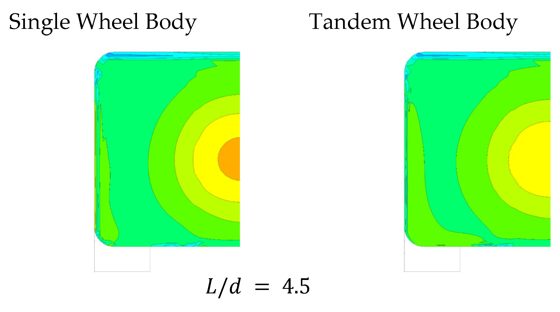
Adding rear wheels to the Fabijanic body resulted in increased lift and drag forces, as shown in Figure 7. Increases in drag force are expected for the longer single-wheel bodies due to the increased viscous forces acting over the increased surface area of each body. While this is true for the longer wheel spacings, drag begins to increase as wheel proximity is reduced for the tandem wheel body, where drag begins to increase substantially. This could be due to the flow interaction between the two wheels on the tandem body. This is investigated further in the following section. For body lengths greater than 5.5 d (ws = 1.5 d), it is evident that the viscous forces are the only mechanism for the increased drag force for both single and tandem wheel bodies, as a gradual reduction is observed in Figure 7. This is supported by the minor increases in the base pressure observed in Figure 8, which shows the wheel and wheelhouse vortices dissipate before reaching the rear wheel for the tandem wheel body.
Flow separations on the side and bottom edges of the single-wheel body are not observed for the tandem wheel configuration (Figure 8). The presence of the rear wheel introduces this separation at the rear wheelhouse and explains the slightly lower body drag force for the tandem wheel body shown in Figure 7 for wheel spacings greater than 1.5 d. Rear-wheel effects are more pronounced in the wake of the body as shown in Figure 9. The wake appears to be larger with a more significant total pressure drop, resulting in a higher drag force acting on the body due to the rear wheel and wheelhouse vortices. These effects reduce as the body length increases, with the 10 d (ws = 6 d) body experiencing a smaller pressure drop than the shorter bodies. It can be seen especially in the region directly behind the rear wheels where the total pressure in the wheel wake returns to the freestream condition, where . The drag reduction trend continues for the tandem wheel body for the longer wheel spacings down to a wheel spacing between 1.5 d for drag forces and 2 d for lift forces where a significant change occurs. The driving mechanisms for this force change are not obvious in the base pressure and wake of the bodies and must be determined by the flow structures around the wheel and wheelhouse, as further discussed in the next section.
3.4. Rear Wheel and Wheelhouse Vortices
Vortices generated at the rear wheel and wheelhouse shown in Figure 10 were compared to the front wheel, and there are some notable differences. To this end, iso-surfaces were plotted with Q-criterion (Q) to follow the vortex cores downstream and monitor their interaction with the rear wheel, wheelhouse, and any other downstream flow structures. The wheelhouse roll-up vortex H is much weaker than it is at the front, as the yaw angle of the inflow is much less. As a consequence, vortices A and B are not formed, and vortex E remains as the sole outflow vortex in the rear wheelhouse. Vortex C is also much smaller and moves into the wheelhouse, passing across the top surface of the wheel before dissipating. Vortex S does not form and is only realised as a minor separation. The jetting vortices L and R produce contrasting forms to the front wheel as L is significantly smaller, and R is the dominant formation of the pair, as can be seen in Figure 10. Rotation from the front wheel reduces the static pressure significantly, which prevents vortex L from forming with the same intensity. Static pressure through the underbody recovers and vortex R is not affected as significantly. These flow structures presented for the baseline case with wheel spacing of 3.0 d are in broad agreement with what was presented by Regert et al. [15]. Given the geometric differences in the reference bodies used, vortex positioning and magnitude are comparable to other studies [14,15,16,25,47,48], concerning wheelhouse flows.
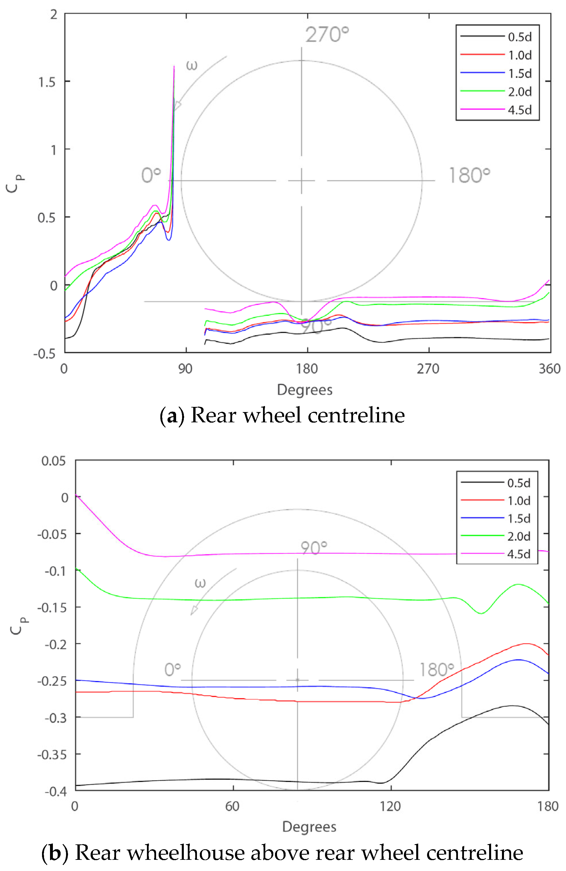
A comparison of pressure coefficients between the front and rear wheels for the baseline case is shown in Figure 11. The pressure on the forward face of the rear wheel is significantly less than what is observed on the front wheel. Centreline pressures are comparable to the original isolated wheel studies of Fackrell and Harvey [49] and the enclosed wheel of Dimitriou and Klussmann [16]. It can be seen that the pressure builds gradually towards the contact patch, where a smaller peak pressure occurs, resulting in the lesser jetting vortices (L and R). The pressure behind the rear wheel is also less than what is observed for the front wheel, suggesting that the primary mechanism for rear wheel drag occurs on the forward face as the jetting vortices are not passing in the wake of the rear wheel. The rear wheelhouse pressure on the other hand is greater than what occurs through the front wheelhouse and is relatively consistent around the top and back of the wheelhouse. This finding also supports the lack of vortices A and B in the rear wheelhouse as no pressure drop is observed in Figure 11b, where the vortices would normally pass between 30° and 150°. The trend in the front wheelhouse pressure is also similar to what was produced on the Fabijanic body in the validation case. It can be seen that the shorter forebody of this model compared to the original Fabijanic geometry, resulting in lower wheelhouse pressure, which also agrees with previous studies [14,18].
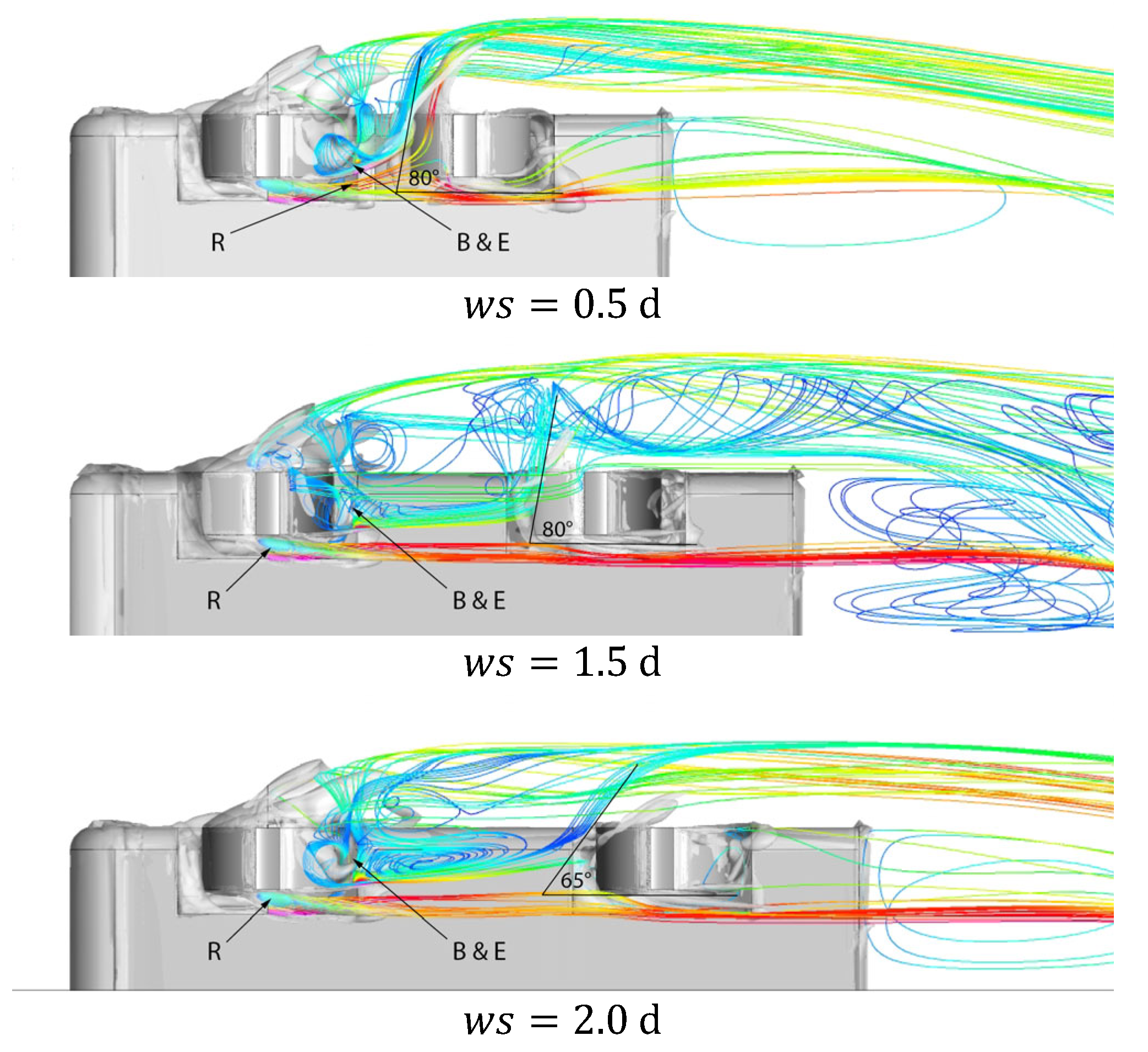
Significant changes in the outboard jetting vortex can be observed in Figure 12 between wheel spacing 1.0 d and 2.0 d. Both spacings are on either side of the minimum drag that occurs at 1.5 d, yet both produce similar total and body forces. A key observation is the yaw angle of the outboard jetting vortex L at 1.0 d, where it is significantly larger than what occurs at longer wheel spacings. Therefore, there must be some vortex interaction occurring between the front and rear wheels at close proximities. No significant changes in the flow structure occur around the rear wheel within the wheel for longer spacings greater than 2.0 d. Flow yaw angle varies very slightly, reducing as the body length increases. This allows for the outboard jetting vortex to remain stronger further downstream. Given that more significant changes occur in the flow structures for wheel spacings less than 1.5 d, wheel spacings longer than 3.0 d have not been considered from here on in.
3.5. Effects of Wheel Proximity on Wheel Flow Structures
Monitoring forces for each wheel and wheelhouse demonstrated which components drive the changes in the overall lift and drag, as shown in Figure 13. The front wheel experienced a 5% drag, which is broadly linear between wheel spacings of 1 d and 6 d. The largest front wheel drag increase occurred at a spacing of 0.5 d. Given that the wheelhouse inflow is consistent for each case, the increase must be a result of the outflow condition due to the proximity of the rear wheel. No significant effect on front wheel lift was observed and the front wheelhouse forces remained relatively consistent with the body variations. The most significant changes occurred at the rear wheel and wheelhouse where an opposing trend can be observed, meaning the reduction in the drag force for the wheel leads to an increase in the drag force for the wheelhouse.
The modelling in Figure 14 shows that effects at the rear wheel and wheelhouse are driven by the outflow condition of the front wheel, though there is no impact in the flow in or through the front wheelhouse. Streamlines are seeded from the inner front wheelhouse to the present outflow direction. Three vortices from the front wheel and wheelhouse are primarily affected, B and E, as they generate the most significant wheelhouse outflow into the underbody and R, which is the inboard jetting vortex. In previous studies [7,14], vortex B flowed out from the wheelhouse alongside the body, however, the presence of the rear wheel draws it towards the underbody. This flow is shown by the stream tracers in Figure 14 for spacings less than 2.0 d, which is a key spacing where the front wheel drag begins to increase. This effect was not observed for a spacing of 3.0 d and is not expected to change significantly for any longer wheel spacing. Vortices B and E are now present in the underbody flow before reaching the rear wheel. For the longer spacing, vortex E is drawn out by the dissipating outboard jetting vortex L; however, this is not the case for wheel spacings less than 2.0 d. The front wheel outflow vortices reach the rear wheelhouse and are projected to be approximately outboard at 2.0 d and upwards of for , creating a greater yawed flow, which is expected to increase drag significantly. This finding is in broad agreement with the original findings of Fabijanic [18], and Regert and Lajos [14], where it was suggested that a yawed flow into the wheelhouse would result in a drag increase for the wheel and wheelhouse.
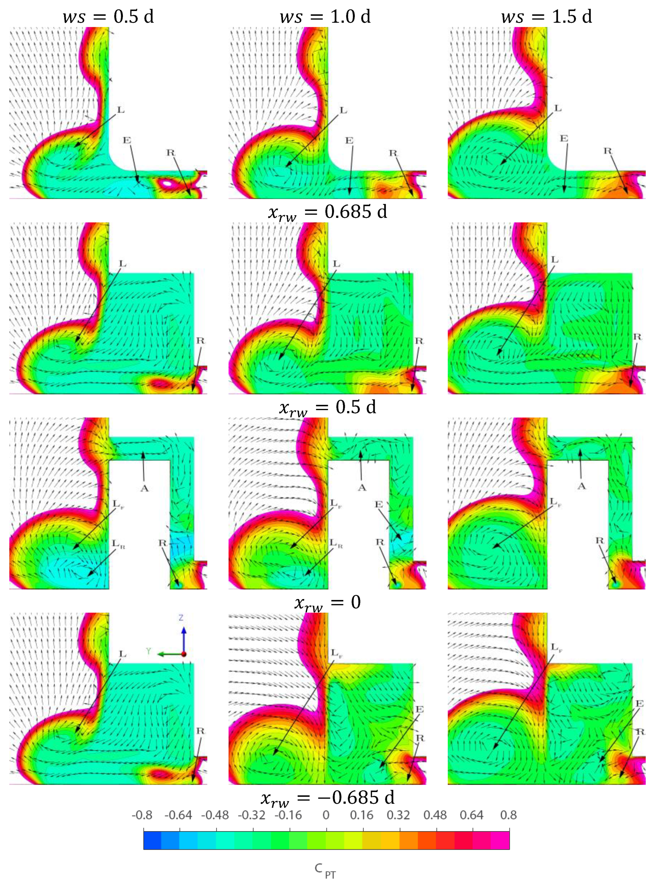
Unlike the front wheel, the presence of upstream vortices has a significant effect on the flow through the rear wheelhouse. As the flow angle increases, flow is drawn out of the rear wheelhouse ahead of the wheel and is directed towards the front jetting vortex, resulting in a large negative pressure region at the front of the wheelhouse. Figure 15 presents the flow through the wheelhouse with normalized vectors to demonstrate the flow rotation and colour using the total pressure coefficient, as calculated using gauge pressure:
where is equal to the freestream pressure.
The increased outflow is visualized in the top row of Figure 15, where vortex E from the front wheel is being drawn outboard by vortex L. It can be seen at positions and that the front wheelhouse outflow is drawn towards vortex L below the vortex core and results in a much larger drop in for vortex . As vortex L moves downstream and moves in the positive Z direction, vortex E feeds into the rotation below the core of vortex L. This motion further strengthens vortex L and redirects the flow from vortices AR and HR into the wake alongside the body. As the wheel spacing increases up to 1.5 d, the interaction between vortices L and E reduces and vortex E remains in the underbody. Therefore, vortex H does not form in the rear wheelhouse nor does vortex A for the shortest spacing; although, it is difficult to quantify their contribution to drag as neither their presence nor absence has a distinct impact on the forces generated. Vortex L is critical to drag and E must be as well, given their interaction at the front wheel resulted in increased drag. Vortex LR, where subscript F and R refer to front and rear wheel vortex formation, forms and is quickly merged with vortex LF for wheel spacings 0.5 d and 1.0 d. It suggests that LF is the dominant flow structure as it is present for all of the longer wheel spacings, with E and LR merging with it in all cases. Crucially, LR does not appear to form at a spacing of 1.5 d and lines up with the point of minimum drag from Figure 13. At this spacing, LF is strong enough to suppress LR without any adverse effect on the rear wheelhouse. This explanation suggests that reducing the size of a jetting vortex, which is a result of the adverse pressure gradient at the wheel–ground contact patch, reduces wheel drag, and agrees with observations made when investigating grooved tyres [50].
Other notable effects are observed in Figure 16 across the rear wheel and wheelhouse surface pressure, which is described using pressure coefficients. The pressure coefficient at the contact patch reduces with wheel spacing from 4.5 d to 1.5 d and begins to increase again as the spacing reduces further. While this result appears to be counter-intuitive, the spacing is small enough such that the front wheel vortices are directed towards the rear wheel contact patch and not around the wheel, which sees an increase in the adverse pressure gradient. The pressure is generally lower at the rear of the wheel for the shorter spacings and significantly lower around the wheelhouse. This lower rear wheelhouse pressure creates suction on the forward face of the rear wheelhouse, thus increasing drag as the wheel proximity reduces. The pressure begins to increase at the back of the wheelhouse, which is caused by the inflow seen in the last row of Figure 15. As observed in the front wheelhouse, vortex A returns for the shorter wheel spacing creating the lower pressure seen at the front and top of the rear wheelhouse, thus leading to a significant reduction in the lift force.
4. Conclusions
This study has provided a detailed analysis of flow structures for a rear wheel and wheelhouse with varying wheel spacing. A significant increase in drag was observed for wheel spacing below 1.5 d, where the outboard jetting vortex was projected laterally into the freestream upwards of . This effect is driven by the front wheelhouse outflow vortices being redirected from the underbody into the rear wheel contact patch. The rear wheel outboard jetting vortex is then energised due to the increased yaw angle of the outflow from the front wheelhouse, which feeds into the rotation of the flow, thus creating a much larger wake alongside the body where significant backflow occurs. This finding at the rear wheelhouse agrees with previous studies on a single wheel in a wheelhouse which demonstrated an increase in the flow yaw angle from 2° to 10°, by changing the forebody geometry, and an increase in wheel and wheelhouse drag. The flow yaw angle is significantly larger into the rear wheelhouse, between 20° and 80°, due to front-wheel proximity. Wheel forces are found to be extremely sensitive to inflow conditions, with front-wheel outflow significantly affecting the flow field around any rearward wheel. This results in an adverse effect on the total drag. Therefore, for any road vehicle consisting of multiple axles in close proximity, additional care should be taken to mitigate the adverse inflow condition to the trailing wheels and hence to reduce the impact the close proximity wheels have on the total drag.
It Is recommended that future work employs a time-resolved method such as LES or IDDES to resolve the highly unsteady flow for close proximity cases such as ws/d > 1.5. In addition, proximities less than ws = 0.5 d with both wheels in a single wheelhouse should be investigated, as this is a common configuration on multi-axle vehicles.
Author Contributions
Conceptualization, R.R., F.S. and S.D.; Methodology, R.R.; Software, R.R.; Validation, R.R.; Formal analysis, R.R.; Resources, F.S. and S.D.; Writing—original draft, R.R.; Writing—review & editing, R.R., F.S. and S.D.; Supervision, F.S. and S.D. All authors have read and agreed to the published version of the manuscript.
Funding
This research received no external funding.
Data Availability Statement
Please contact the corresponding author for any desired research data presented in this paper.
Acknowledgments
This work formed part of a Master Thesis at Macquarie University, and the lead author would like to thank the supervisors for their input and support.
Conflicts of Interest
The authors declare no conflict of interest.
References
- Schuetz, T.C. Aerodynamics of Road Vehicles, 5th ed.; SAE International: Warrendale, PA, USA, 2015. [Google Scholar] [CrossRef]
- Demarco, K.; Stratton, J.; Chinavare, K.; VanHouten, G. The Effects of Mass and Wheel Aerodynamics on Vehicle Fuel Economy; SAE Technical Papers; SAE International: Warrendale, PA, USA, 2017. [Google Scholar] [CrossRef]
- Palin, R.; Johnston, V.; Johnson, S.; D’Hooge, A.; Duncan, B.; Gargoloff, J.I. The Aerodynamic Development of the Tesla Model S—Part 1: Overview; SAE Technical Papers; Series 1; SAE International: Warrendale, PA, USA, 2012. [Google Scholar] [CrossRef]
- Elofsson, P.; Bannister, M. Drag Reduction Mechanisms Due to Moving Ground and Wheel Rotation in Passenger Cars; SAE Technical Papers; SAE International: Warrendale, PA, USA, 2002. [Google Scholar] [CrossRef]
- Mercker, E.; Breuer, N.; Berneburg, H.; Emmelmann, H.J. On the Aerodynamic Interference Due to the Rolling Wheels of Passenger Cars; SAE Technical Papers; SAE International: Warrendale, PA, USA, 1991. [Google Scholar] [CrossRef]
- Wickern, G.; Zwicker, K.; Pfadenhauer, M. Rotating Wheels—Their Impact on Wind Tunnel Test Techniques and on Vehicle Drag Results; SAE Technical Papers; SAE International: Warrendale, PA, USA, 1997; Volume 106, pp. 254–270. [Google Scholar]
- Krajnović, S.; Sarmast, S.; Basara, B. Numerical Investigation of the Flow Around a Simplified Wheel in a Wheelhouse. J. Fluids Eng. 2011, 133, 111001. [Google Scholar] [CrossRef]
- Wiedemann, J. The Influence of Ground Simulation and Wheel Rotation on Aerodynamic Drag Optimization-Potential for Reducing Fuel Consumption; SAE Technical Papers; SAE International: Warrendale, PA, USA, 1996. [Google Scholar] [CrossRef]
- Fackrell, J.E. The Aerodynamics of an Isolated Wheel Rotating in Contact with the Ground; University of London: London, UK, 1974. [Google Scholar]
- Cogotti, A. Aerodynamic Characteristics of Car Wheels. In Technological Advances in Vehicle Design; Special Publication SP; Inderscience Enterprises Limited: Geneva, Switzerland, 1983. [Google Scholar]
- Axon, L.; Garry, K.; Howell, J. An Evaluation of CFD for Modelling the Flow Around Stationary and Rotating Isolated Wheels; SAE Technical Papers; Series 1; SAE International: Warrendale, PA, USA, 1998. [Google Scholar] [CrossRef]
- Axon, L.; Garry, K.; Howell, J. The Influence of Ground Condition on the Flow Around a Wheel Located within a Wheelhouse Cavity; SAE Technical Papers; Series 1; SAE International: Warrendale, PA, USA, 1999. [Google Scholar] [CrossRef]
- Diasinos, S.; Barber, T.J.; Doig, G. The effects of simplifications on isolated wheel aerodynamics. J. Wind Eng. Ind. Aerodyn. 2015, 146, 90–101. [Google Scholar] [CrossRef]
- Régert, T.; Lajos, T. Description of flow field in the wheelhouses of cars. Int. J. Heat Fluid Flow 2007, 28, 616–629. [Google Scholar] [CrossRef]
- Regert, T.; Schwarczkopf, A.; Lajos, T. The Effect of Wheels on the Aerodynamic Characteristics of an Ahmed Body. In Proceedings of the 3rd European Automotive CFD Conference, Frankfurt, Germany, 5–6 July 2007; pp. 1–11. [Google Scholar]
- Dimitriou, I.; Klussmann, S. Aerodynamic Forces of Exposed and Enclosed Rotating Wheels as an Example of the Synergy in the Development of Racing and Passenger Cars; SAE Technical Papers; Series 1; SAE International: Warrendale, PA, USA, 2010. [Google Scholar] [CrossRef]
- Skea, A.F.; Bullen, P.R.; Qiao, J. CFD Simulations and Experimental Measurements of the Flow over a Rotating Wheel in a Wheel Arch; SAE Technical Papers; Series 1; SAE International: Warrendale, PA, USA, 2000. [Google Scholar] [CrossRef]
- Fabijanic, J. An Experimental Investigation of Wheel-Well Flows; SAE Technical Papers; SAE International: Warrendale, PA, USA, 1996; pp. 161–172. [Google Scholar]
- Régert, T.; Lajos, T. Investigation of Flow Field Past Rotating Wheels of Cars. Model Fluid Flow, Budapest. Available online: https://www.ara.bme.hu/~regert/publications/regert_lajos_cmff2003.pdf (accessed on 10 February 2020).
- Viswanathan, V. Aerodynamics of a Rotating Wheel in a Wheelhouse; Technische Universiteit Delft: Delft, The Netherlands, 2017; Available online: https://repository.tudelft.nl/islandora/object/uuid:2c964dfc-8b3d-44ba-9e3d-cd22704aa862?collection=education (accessed on 15 February 2020).
- Krajnović, S.; Sarmast, S. LES of the Flow around a Generic Wheel in a Wheelhouse. In Proceedings of the 3rd Joint US-European Fluids Engineering Summer Meeting, Montreal, QC, Canada, 1–5 August 2010; Volume 563. [Google Scholar]
- Thivolle-Cazat, E.; Gilliéron, P. Flow analysis around a rotating wheel. In Proceedings of the 13th International Symposium on Applications of Laser Techniques to Fluid Mechanics, Lisboa, Portugal, 26–29 June 2006; pp. 26–29. [Google Scholar]
- Johnson, D. A Qualitative and Quantitative Aerodynamic Study of a Rotating Wheel Inside a Simplified Vehicle Body and Wheel Liner Cavity; SAE Technical Papers; SAE International: Warrendale, PA, USA, 2019; pp. 1–16. [Google Scholar]
- Rajaratnam, E.; Walker, D. Investigation of wheelhouse flow interaction and the influence of lateral wheel displacement. Energies 2019, 12, 3340. [Google Scholar] [CrossRef]
- Wäschle, A. The Influence of Rotating Wheels on Vehicle Aerodynamics—Numerical and Experimental Investigations. SAE Tech. Pap. Ser. 2007, 1, 776–790. [Google Scholar]
- Vdovin, A. Numerical and Experimental Investigations on Aerodynamic and Thermal Aspects of Rotating Wheels. Available online: https://publications.lib.chalmers.se/publication/220614-numerical-and-experimental-investigations-on-aerodynamic-and-thermal-aspects-of-rotating-wheels (accessed on 1 June 2015).
- Bolzon, M.D.P.; Sebben, S.; Broniewicz, A. Effects of Wheel Configuration on the Flow Field and the Drag Coefficient of a Passenger Vehicle. Int. J. Automot. Technol. 2019, 20, 763–777. [Google Scholar] [CrossRef]
- Brandt, A.; Berg, H.; Bolzon, M.; Josefsson, L. The effects of wheel design on the aerodynamic drag of passenger vehicles. SAE Tech. Pap. 2019, 1, 1279–1299. [Google Scholar] [CrossRef]
- Mavuri, S.P. Aerodynamic Analysis of Vehicle Wheel-Housings. Ph.D. Thesis, RMIT University, Melbourne, Australia, 2009. [Google Scholar]
- Schwarczkopf, A.; Regert, T.; Lajos, T. Investigation of Simple Possibilities for Reduction of Drag due to the Wheels of Road Vehicles. In Proceedings of the 4th European Automotive Simulation Conference, Munich, Germany, 6–7 July 2009. [Google Scholar]
- Gulyás, A.; Bodor, Á.; Regert, T.; Jánosi, I.M. PIV measurement of the flow past a generic car body with wheels at LES applicable Reynolds number. Int. J. Heat Fluid Flow 2013, 43, 220–232. [Google Scholar] [CrossRef]
- Sumner, D. Two circular cylinders in cross-flow: A review. J. Fluids Struct. 2010, 26, 849–899. [Google Scholar] [CrossRef]
- Alam, M.M.; Moriya, M.; Takai, K.; Sakamoto, H. Fluctuating fluid forces acting on two circular cylinders in a tandem arrangement at a subcritical Reynolds number. J. Wind Eng. Ind. Aerodyn. 2003, 91, 139–154. [Google Scholar] [CrossRef]
- Bearman, P.W.; Wadcock, A.J. The interaction between a pair of circular cylinders normal to a stream. J. Fluid Mech. 1973, 61, 499–511. [Google Scholar] [CrossRef]
- Hoerner, S.F. (Ed.) Fluid-Dynamic Drag: Practical Information on Aerodynamic Drag and Hydrodynamic Resistance; Midland Park, NJ, USA, 1958. [Google Scholar]
- Igarashi, T. Characteristics of the Flow Around Two Circular Cylinders Arranged in Tandem—1. Bull. JSME 1981, 24, 323–331. [Google Scholar] [CrossRef]
- Spagnolo, S.; Zhang, X.; Hu, Z.; Angland, D. Numerical simulations of single and tandem wheels for aerodynamic loads prediction. In Proceedings of the 22nd AIAA Computational Fluid Dynamics Conference, Dallas, TX, USA, 22–26 June 2015; pp. 1–15. [Google Scholar]
- Spagnolo, S.; Zhang, X.; Hu, Z.; Stalnov, O.; Angland, D. Unsteady aerodynamics of single and tandem wheels. J. Fluids Struct. 2017, 69, 121–136. [Google Scholar] [CrossRef]
- Rasani, M.R.; Shamsudeen, A.; Harun, Z.; Mahmood, W.M.F.W. A computational aerodynamic study of tandem rotating wheels in contact with the ground. Int. J. Eng. Technol. 2018, 7, 133–136. [Google Scholar] [CrossRef]
- Shih, T.H.; Liou, W.W.; Shabbir, A.; Yang, Z.; Zhu, J. A new k-ϵ eddy viscosity model for high reynolds number turbulent flows. Comput. Fluids 1995, 24, 227–238. [Google Scholar] [CrossRef]
- Menter, F.R. Two-equation eddy-viscosity turbulence models for engineering applications. AIAA J. 1994, 32, 1598–1605. [Google Scholar] [CrossRef]
- Krajnović, S.; Davidson, L. Numerical study of the flow around a bus-shaped body. J. Fluids Eng. Trans. ASME 2003, 125, 500–509. [Google Scholar] [CrossRef]
- Krajnović, S.; Fernandes, J. Numerical simulation of the flow around a simplified vehicle model with active flow control. Int. J. Heat Fluid Flow 2011, 32, 192–200. [Google Scholar] [CrossRef]
- Roache, P. A Method for Uniform Reporting of Grid Refinement Studies. J. Fluids Eng. 1994, 116, 405–413. [Google Scholar] [CrossRef]
- Fu, C.; Bounds, C.; Uddin, M. Fine Tuning the SST. k-ω Turbulence Model Closure Coefficients for Improved NASCAR Cup Racecar Aerodynamic Predictions. SAE Int. J. Adv. Curr. Prac. Mobil. 2019, 1, 1226–1232. [Google Scholar] [CrossRef]
- Zhang, C.; Bounds, C.P.; Foster, L.; Uddin, M. Turbulence modeling effects on the CFD predictions of flow over a detailed full-scale sedan vehicle. Fluids 2019, 4, 148. [Google Scholar] [CrossRef]
- Ramani, S.K.; Krishna, S. Experimental Investigation of Wheelhouse Flow Using PIV; Technische Universiteit Delft: Delft, The Netherlands, 2018; Available online: https://repository.tudelft.nl/islandora/object/uuid:f37dc203-6fce-488d-926f-c2b30be5caf9?collection=education (accessed on 15 February 2020).
- Bonitz, S.; Larsson, L.; Sebben, S. Unsteady pressure analysis of the near wall flow downstream of the front wheel of a passenger car under yaw conditions. Int. J. Heat Fluid Flow 2018, 73, 188–198. [Google Scholar] [CrossRef]
- Fackrell, J.E.; Harvey, J. The Flow Field and Pressure Distribution of An Isolated Road Wheel. In Advances in Road Vehicle Aerodynamics; BHRA Fluid Engineering: Cranfield, UK, 1973. [Google Scholar]
- Josefsson, E.; Hobeika, T.; Sebben, S.; Urquhart, M. Investigation of Tyre Pattern Effect on the Aerodynamics of a Passenger Vehicle. J. Fluids Eng. 2022, 144, 111209. [Google Scholar] [CrossRef]
Figure 1.
Vortex skeleton produced by Krajnovic et al. [7].
Figure 1.
Vortex skeleton produced by Krajnovic et al. [7].

Figure 2.
Modified Fabijanic model with tandem wheels.

Figure 3.
Computational domain and boundary conditions.
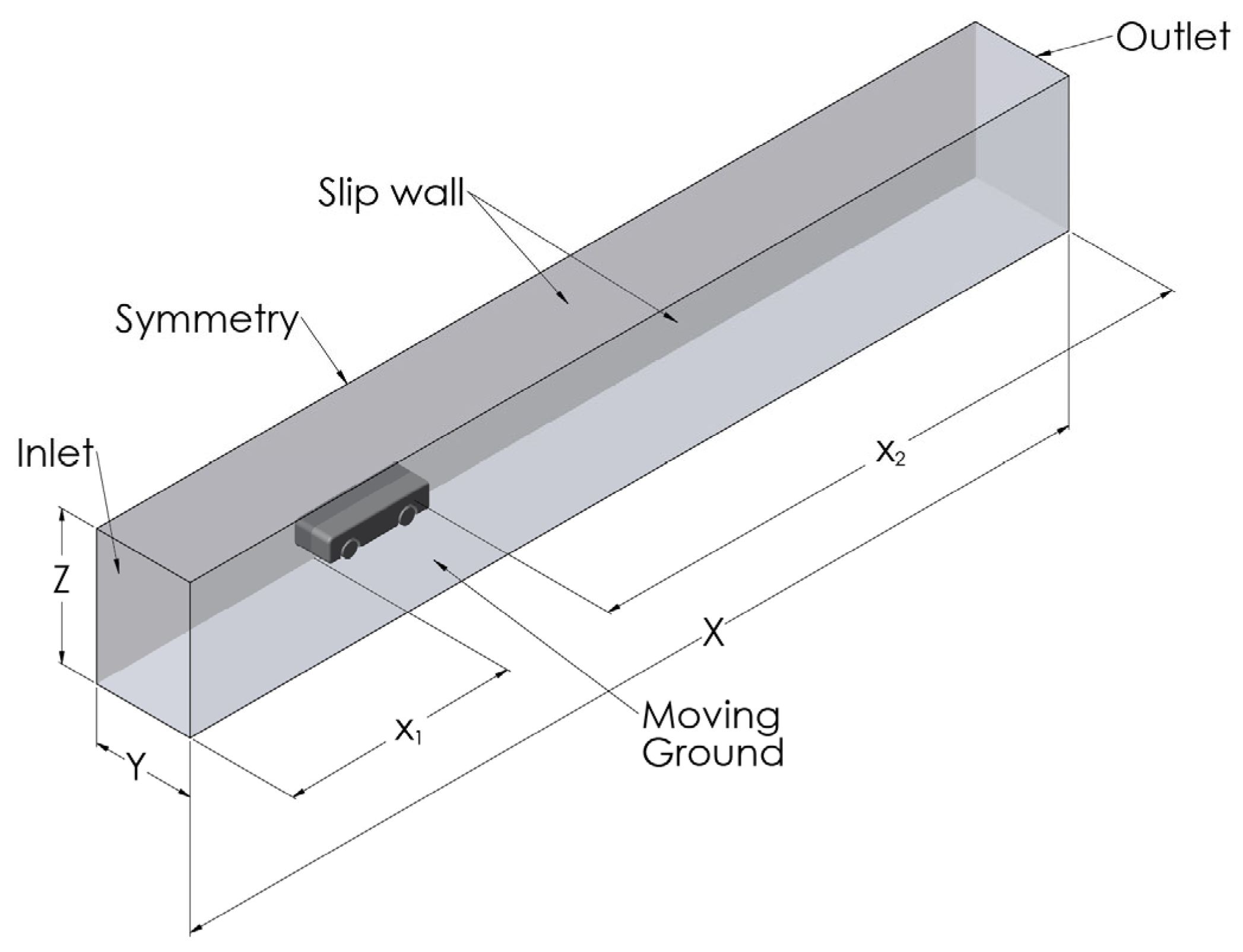
Figure 4.
Mesh visualisation of geometry and critical areas.

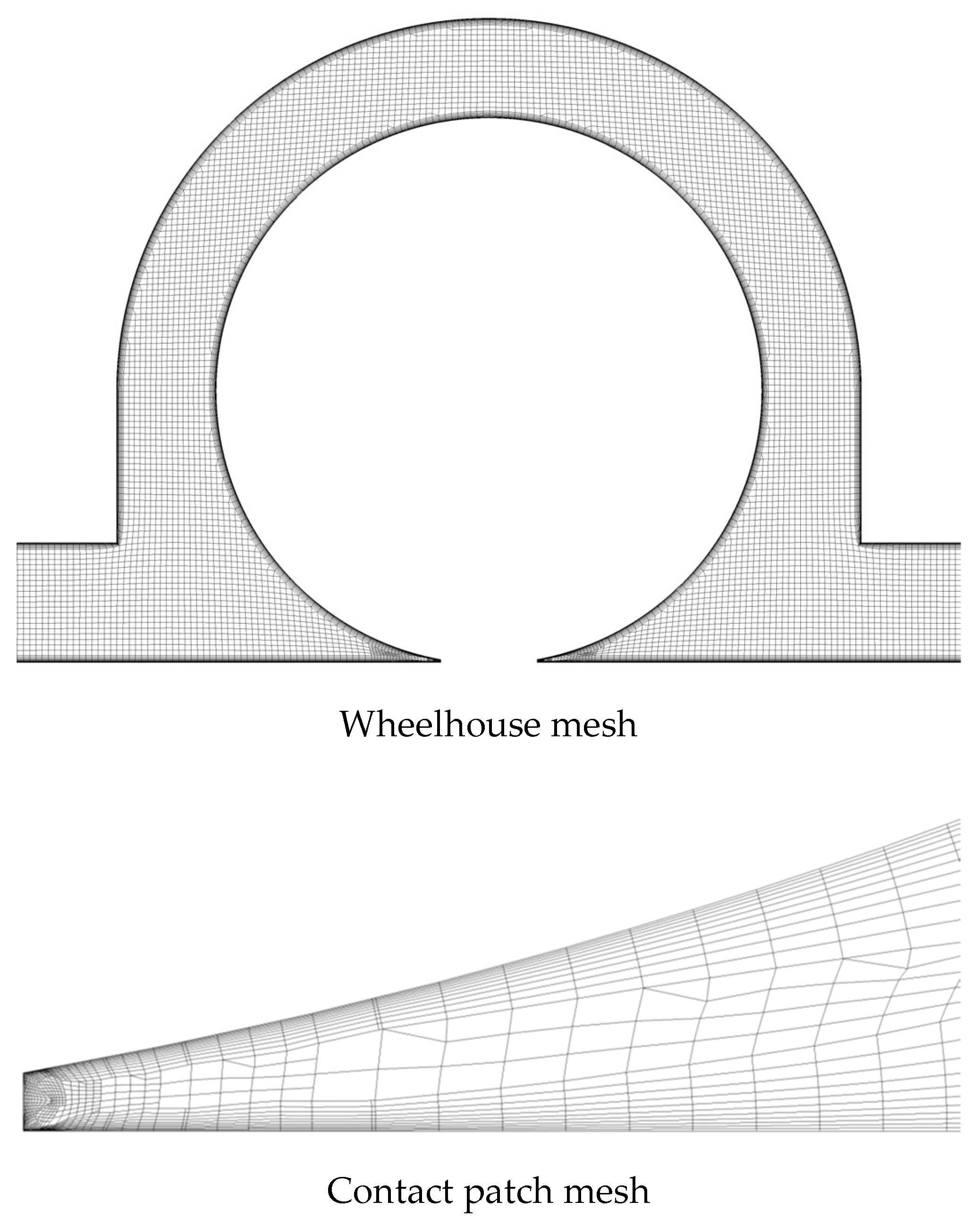
Figure 5.
Results of the Grid verification study.

Figure 6.
comparison of the Fabijanic body for the chosen turbulence model and previous studies [14,18].
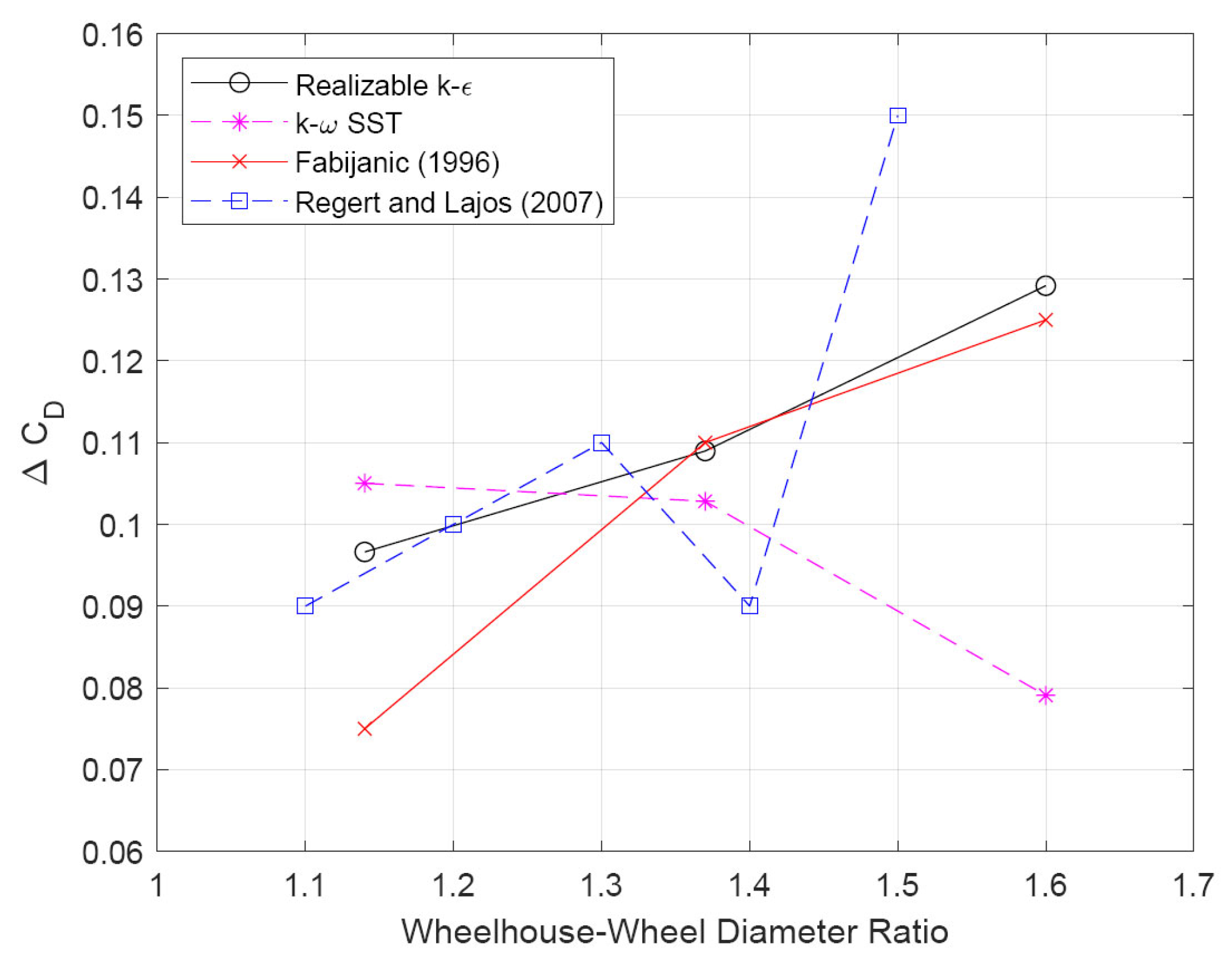
Figure 7.
Drag force coefficient (upper) and lift force coefficient (lower) for single and tandem wheel configurations.
Figure 7.
Drag force coefficient (upper) and lift force coefficient (lower) for single and tandem wheel configurations.
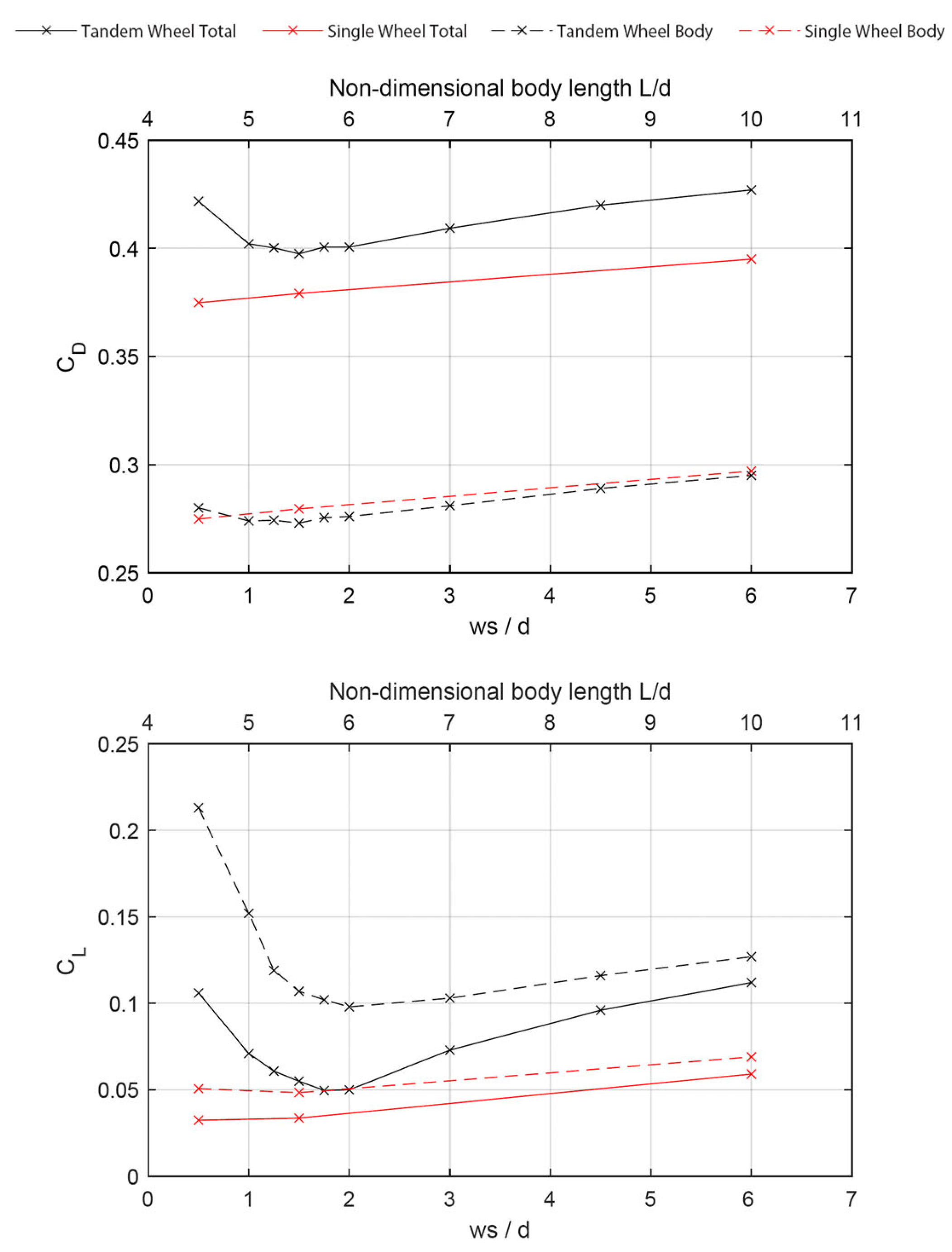
Figure 8.
Base pressure coefficient contour plots for rear of the body.

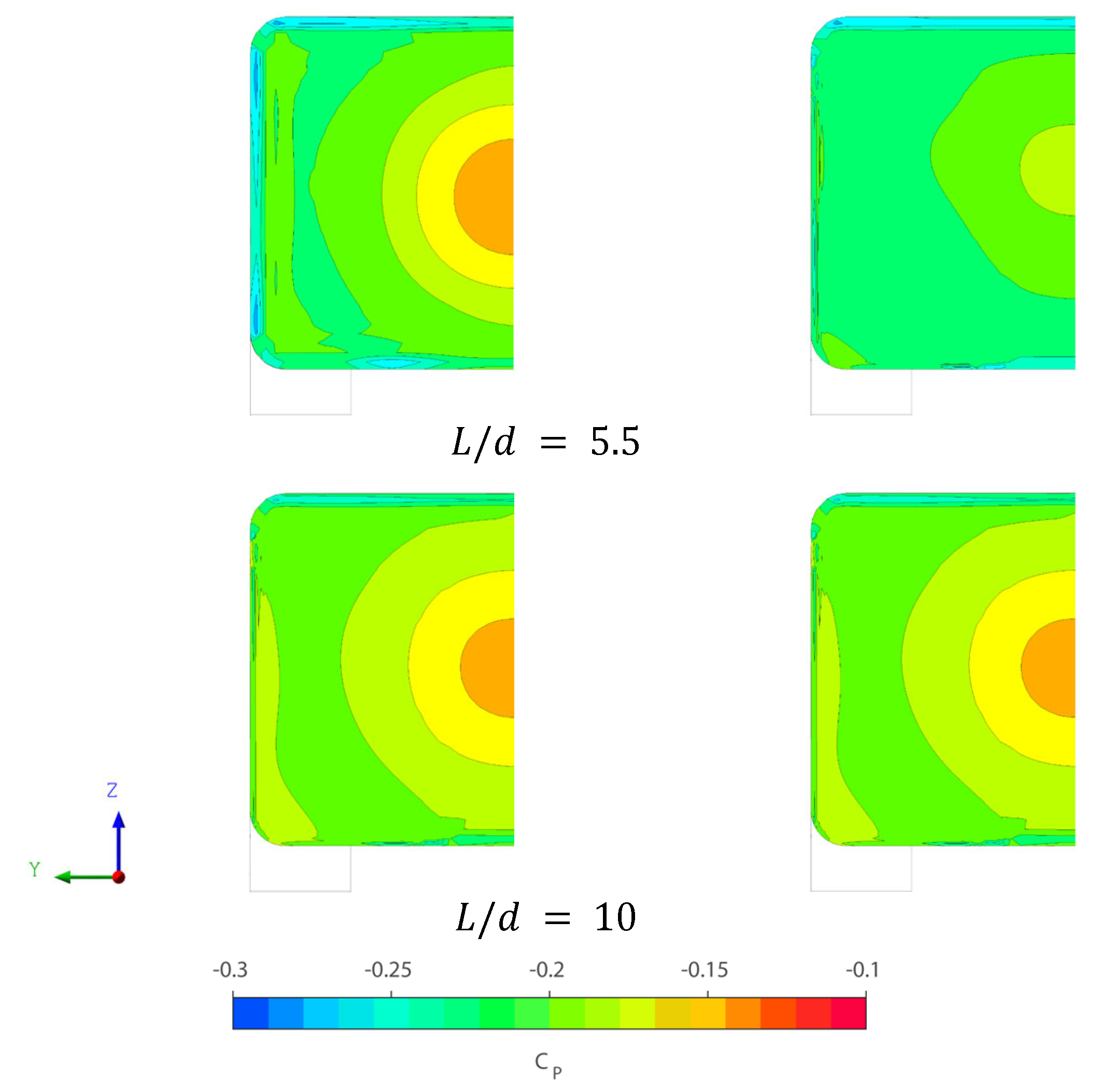
Figure 9.
Total pressure coefficient 1 d rear of body of single (Left) and tandem (Right) wheel bodies. Top to bottom: wheel spacing , , .
Figure 9.
Total pressure coefficient 1 d rear of body of single (Left) and tandem (Right) wheel bodies. Top to bottom: wheel spacing , , .
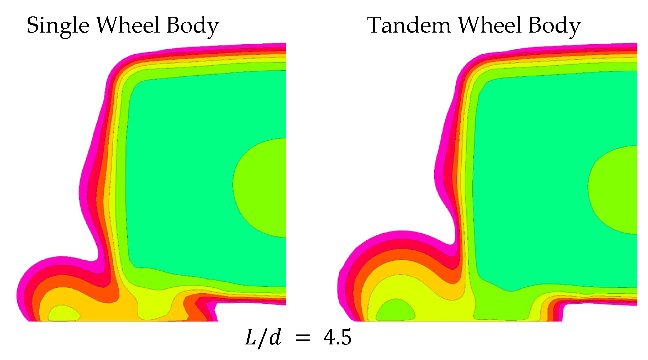

Figure 10.
Wheel and wheelhouse vortices for the tandem wheel configuration with 3.0 d spacing. Q = .
Figure 10.
Wheel and wheelhouse vortices for the tandem wheel configuration with 3.0 d spacing. Q = .

Figure 11.
Wheel and wheelhouse pressure for the tandem wheel body with the wheel spacing of 3.0 d.
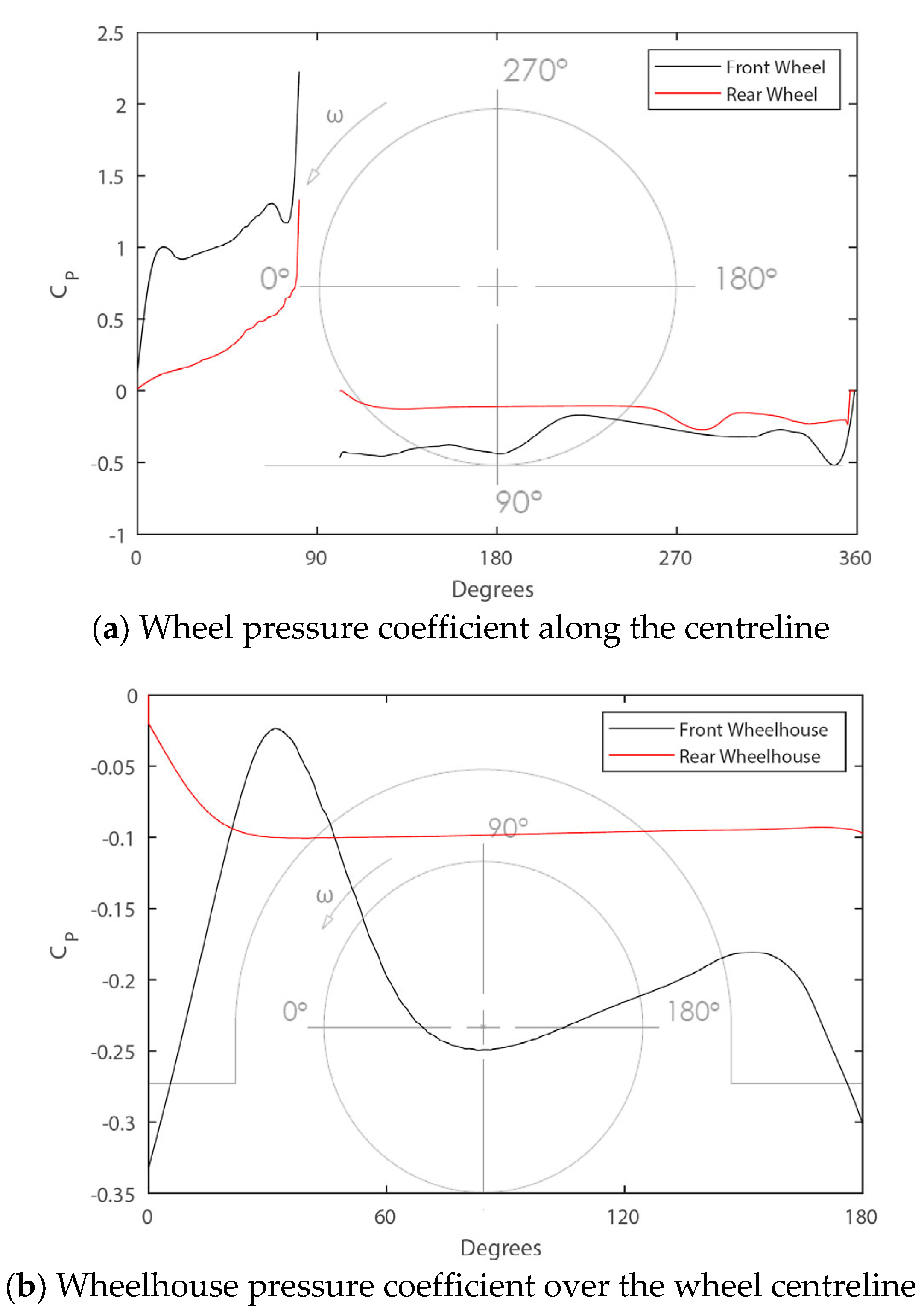
Figure 12.
Rear wheel flow structures for different wheel spacings. Q = .
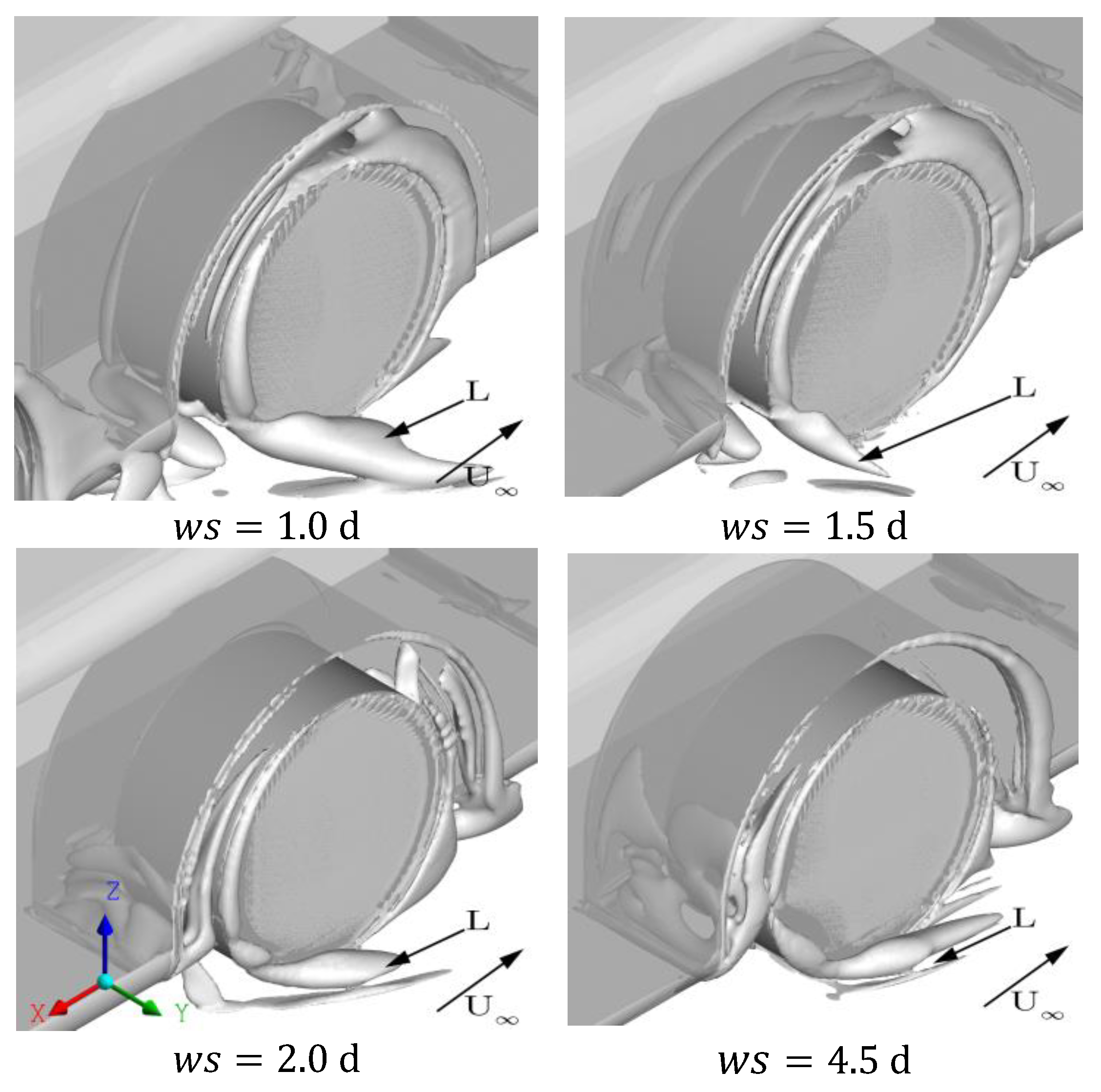
Figure 13.
Force coefficients for the tandem wheel body.
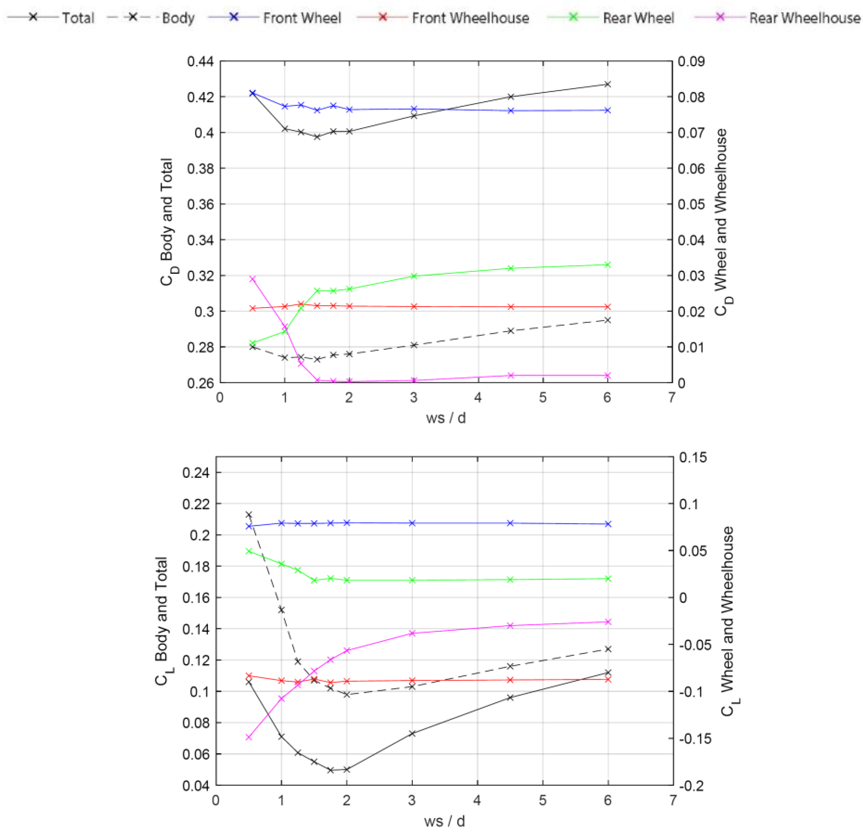
Figure 14.
Bottom view of the tandem wheel bodies. Rake placed for vortices B, E and R.

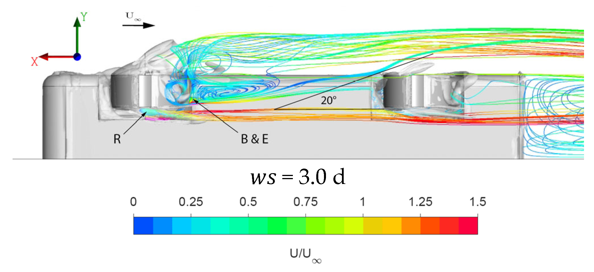
Figure 15.
Total pressure coefficient across the streamwise planes through the rear wheelhouse.

Figure 16.
Wheel and wheelhouse pressure coefficients for varying wheel spacings.

Table 1.
Detailed modified Fabijanic body dimensions for the baseline configuration.
| H | 127 | ws | 229.8 | rwh | 52.3 | d = le = te | 76.6 |
| L | 536.2 | h | 16.8 | g | 14 | w | 36.2 |
| W | 190.5 | r1 | 25 | wwh | 50.5 | ||
| Dimensions in mm | |||||||
Table 2.
Body length and wheel spacing dimensions for modified wheel spacing variation.
| 0.5 d | 1.0 d | 1.5 d | 2 d | 4.5 d | 6.0 d | |
|---|---|---|---|---|---|---|
| L | 344.7 | 383 | 421.3 | 536.2 | 651.1 | 766 |
| ws | 36.3 | 76.6 | 114.9 | 153.2 | 344.7 | 459.6 |
| Dimensions in mm | ||||||
Disclaimer/Publisher’s Note: The statements, opinions and data contained in all publications are solely those of the individual author(s) and contributor(s) and not of MDPI and/or the editor(s). MDPI and/or the editor(s) disclaim responsibility for any injury to people or property resulting from any ideas, methods, instructions or products referred to in the content. |
© 2023 by the authors. Licensee MDPI, Basel, Switzerland. This article is an open access article distributed under the terms and conditions of the Creative Commons Attribution (CC BY) license (https://creativecommons.org/licenses/by/4.0/).
Share and Cite
MDPI and ACS Style
Radovic, R.; Salehi, F.; Diasinos, S. A Detailed Numerical Study on Aerodynamic Interactions of Tandem Wheels on a Generic Vehicle. Fluids 2023, 8, 281. https://doi.org/10.3390/fluids8100281
AMA Style
Radovic R, Salehi F, Diasinos S. A Detailed Numerical Study on Aerodynamic Interactions of Tandem Wheels on a Generic Vehicle. Fluids. 2023; 8(10):281. https://doi.org/10.3390/fluids8100281
Chicago/Turabian StyleRadovic, Radoje, Fatemeh Salehi, and Sammy Diasinos. 2023. "A Detailed Numerical Study on Aerodynamic Interactions of Tandem Wheels on a Generic Vehicle" Fluids 8, no. 10: 281. https://doi.org/10.3390/fluids8100281