
Modeling of Indirect Evaporative Cooling Systems: A Review

Department of Energy, Politecnico di Milano, Via Lambruschini 4, 20156 Milano, Italy
*
Author to whom correspondence should be addressed.
Fluids 2023, 8(11), 303; https://doi.org/10.3390/fluids8110303
Submission received: 15 September 2023
/
Revised: 3 November 2023
/
Accepted: 16 November 2023
/
Published: 18 November 2023
(This article belongs to the Collection Challenges and Advances in Heat and Mass Transfer)
Abstract
:Air-to-air indirect evaporative cooling (IEC) systems are particular heat exchangers that use the latent heat of evaporation of water to cool down an air stream, without increasing its specific humidity, thus guaranteeing adequate thermohygrometric conditions in the refrigerated environment with low energy consumption. Dew-point indirect evaporative cooling (DIEC) systems are based on the IEC technology, but they recirculate a part of the air taken from the room to be refrigerated, in order to possibly achieve a lower air temperature. IEC and DIEC systems are becoming increasingly common these years, as they can ensure a good efficiency, minimizing the environmental impact of the air-conditioning system. Consequently, it has been necessary to develop models, both analytical and numerical, to quickly and accurately design this type of system and to predict their performance. This paper presents a review of the analytical and numerical models developed specifically for IEC and DIEC systems, highlighting their method, main innovations and advantages, and possible limitations. From this analysis, it emerged that analytical models have been developed since the late 1990s and only few of them are suitable for DIEC heat exchangers, while numerical models for both IEC and DIEC systems are gaining popularity in recent years. Almost all the analyzed models have been validated by comparison with numerical and/or experimental data, showing a maximum discrepancy within 10% in the majority of the cases. However, the validations were performed for a few specific cases, so in real applications it might be difficult to associate the model boundary conditions and the heat exchangers operating conditions, such as nozzles orientations, plates materials, water flow rates, and configurations. Another common limitation concerns the modeling of some properties, as wettability factor and air density, which might affect the accuracy of the results.
1. Introduction
At present, heating, ventilation, and air conditioning (HVAC) systems have become essential for individuals residing in both developed and developing nations, consequently constituting a substantial portion of global primary energy consumption [1]. Specifically, the energy usage associated with indoor cooling has gained greater significance compared to a few decades ago, owing to the increased demand for optimal comfort conditions and the rise in average outdoor temperatures caused by climate change [2]. For these reasons, innovative types of air conditioning systems that can minimize the environmental footprint in comparison to conventional ones are gaining popularity.
In this particular context, evaporative cooling, which is based on the transfer of heat and mass between air and water [3], emerges as a highly promising solution, as it gives the possibility to use the latent heat of vaporization of water to refrigerate the air. There are two main types of evaporative cooling: direct evaporative cooling (DEC) and indirect evaporative cooling (IEC). DEC systems cool the air by adding moisture to it, whereas IEC systems can refrigerate the environment without increasing its humidity ratio [4]. As a result, IEC systems are particularly well-suited for a wide variety of applications [5], such as: residential buildings [6], agricultural storage and livestock air-conditioning [7], greenhouses [8], and pharmaceutics [9].
In the last few years, two types of IEC systems have become of great interest for engineering applications: the regular indirect evaporative cooling system, and the dew-point indirect evaporative cooling (DIEC) system. In particular, the DIEC working principle is an improvement of the IEC technology. In fact, the IEC system allows the product air to be cooled down to the wet-bulb temperature of the working air, while the product air in the DIEC system can reach the dew-point temperature of the working air [10].
Many review studies concerning evaporative cooling have been conducted in recent years. In particular, Glanville et al. [11] studied the evolution of DIEC systems performance, in the context of the evaporative cooling technology development. Duan et al. [12] presented a comprehensive description of the IEC working principle, performance parameters, operating conditions, and possible future developments, also describing many studies concerning experimental analyses, models, and social-technical aspects, such as cost, environmental impact, life-cycle assessment, and potential market barriers. Wani et al. [13] analyzed the energy saving possibilities of applying the Maisotsenko cycle (M-cycle) in evaporative cooling applications. Amer et al. [14] described in detail the DEC, IEC, and combined DEC/IEC systems, with a particular focus on their possible applications. Porumb et al. [3] analyzed the main evaporative cooling technologies, presenting their construction principles, flow schemes, working conditions, performance parameters, and possible applications in different sectors. Cuce et al. [15] described the working principle, thermal performance, and environmental impact of some evaporative cooling systems, with a particular focus on their advantages and disadvantages in building applications. Mahmood et al. [16] presented an overview of the M-cycle and its applications in HVAC systems, comparing this technology with the traditional evaporative cooling. Yang et al. [17] analyzed the possibility of improving the evaporative cooling systems performance through enhanced systems, based on the use of desiccants and/or membranes, which can lead to the design of new smaller cooling devices. Sofia et al. [18] presented the DEC, IEC, and combined DEC/IEC technologies, investigating the possibility of adding heat pipes to evaporative coolers, in order to improve their performance. Sajjad et al. [1] described in detail a large number of IEC configurations and their possible combinations, also analyzing the effects of system geometry, working conditions, and plates material on the cooling performance. Lv et al. [10] investigated different types of porous materials used for IEC systems, comparing their performance and suggesting how to model them. Pacak and Worek [19] analyzed the working principles, performance parameters, and applications of the DIEC technology, describing some experimental studies, numerical and analytical models, and optimization techniques. Yang et al. [20] presented an in-depth description of the possible IEC geometries and configurations (including hybrid IEC systems), with a particular focus on the choice of materials and spray water systems which can improve the performance. Zhu et al. [21] described the working principle and characteristics of DIEC systems, analyzing their applications, modeling techniques, and available experimental works. Finally, Kapilan et al. [22] presented a review work concerning the characteristics, working principle, and possible future applications of evaporative cooling systems. However, in each of these studies there is no more than a small section dedicated to describing IEC system modeling techniques. Consequently, to date, this topic has not been analyzed in sufficient depth in the literature.
As the IEC technology is becoming widespread, there have been many attempts of modeling a complete IEC system or only a part of it, both through analytical and numerical, especially computational fluid dynamics (CFD), models. Therefore, the scope of this review is to provide a comprehensive description of the different types of models developed to predict the behavior and performance of IEC and DIEC systems, highlighting the current limits and possible future developments in the field. This work can be useful to direct future research towards what is missing in the field of IEC system modeling, namely as a practical guide to quickly understand what has already been done and what is lacking in this area.
The study was conducted through an accurate research based on keywords in the main databases available online.
2. IEC Systems
During the operation of an IEC system, the primary (or product) air enters a dry channel, while the secondary (or working) air enters a wet channel, adjacent to the dry one [12]. The channels are separated by a thin heat exchanging wall, which can be made of different materials [4]. Water is delivered by a pump and it is sprayed on the wet channels, in order to generate a film over the plate surface [20].
The wet channel receives heat from the dry channel thanks to the evaporation of the water film on the wet side of the plate, and thus the primary air is cooled down, while the secondary air is heated, as it absorbs the latent heat of vaporization of water [12]. Then, the cooled primary air is released into the room to be conditioned, and the secondary air is exhausted outside the building.
There are many indicators used to evaluate the performance of an IEC system, but the most common are the wet-bulb effectiveness, , the dew-point effectiveness, , the cooling capacity, , and the coefficient of performance, [20]. These performance indicators are defined as:
where: is the primary air inlet temperature, is the primary air outlet temperature, is the wet-bulb temperature of the secondary air at the inlet, is the dew-point temperature of the secondary air at the inlet, is the primary air mass flow rate, is the specific heat at constant pressure of the primary air, and is the mechanical power.
According to the airstreams directions, IEC systems are classified into two categories: counter-flow and cross-flow [20]. As parallel-flow IEC systems have the same drawbacks of the counter-flow ones, but with a lower effectiveness than cross-flow systems, their application has been limited, especially in recent years.
As shown in Figure 1, in a counter-flow configuration the primary air (red) and the secondary air (blue) flow parallel in opposite directions, while in a cross-flow configuration the two airstreams are perpendicular to each other [23]. As a consequence, an IEC system in counter-flow configuration can be modeled by using a simple one-dimensional (1-D) model, but when the configuration is cross-flow, at least a two-dimensional (2-D) model is needed [20]. Even if counter-flow heat exchangers are potentially easier to model and have a higher effectiveness with respect to cross-flow heat exchangers under the same working conditions, a pure counter-flow heat exchanger is not easy to embed in the limited space available in most HVAC systems [24]. For these reasons, both cross-flow and counter-flow IEC are used in many fields, and the choice between them depends on the requirements in each specific application. Therefore, it is necessary to develop models for both the counter-flow and the cross-flow configuration.
2.1. Analytical Models
Analytical models for predicting the performance of IEC systems have always been widespread, as they are usually quite simple and have a relatively low computational cost.
One of the first analytical models for IEC systems was developed by Alonso et al. [25] in 1998. This model, which could be used for all types of IEC systems, is based on some simplifying assumptions, such as: absence of heat exchange between the IEC system and the environment, negligible viscous dissipation, stable and incompressible flow, constant mass flow rates in the channels, constant latent heat of vaporization of water, surfaces of the channels completely, and uniformly wetted by water. The equations used in the model are the heat and mass transfer equations applied to an infinitesimal element of an IEC system, which is assumed to be equivalent to the complete IEC heat exchanger. The main novelty introduced by this work is the definition of an equivalent temperature that allows to study the flows of primary and secondary air independently. This model was validated against experimental results found in literature, and the average difference between the temperatures obtained through the model and the experimental data was . Even though the model is quite versatile and can be used for all types of IEC systems, the assumption of stable flow with constant air density can affect the accuracy of the results when the plate geometry is complex and the temperature variations are large. Moreover, an IEC system plate that is completely and uniformly wetted by water is the best case scenario, and it can be a good description of reality only if the water flow rate is very high, namely if in the heat exchanger wet channels there is always excess water. However, in many real applications it is necessary to define the wetted surface fraction, which will likely be lower than one. Therefore, this model will most likely overestimate the cooling performance with respect to experimental data.
In the same period, Stoitchkov and Dimitrov [26] developed a model to calculate the effectiveness of cross-flow IEC systems with a flowing down water film. The authors presented a correction method for the effectiveness, based on the work of Maclaine-Cross and Banks [27]. Moreover, they estimated the mean surface water temperature and also took into account the barometric pressure. For all these reasons, this model provides an effective and fast procedure to predict the performance of wet surface heat exchangers. The wet-bulb effectiveness results obtained through the model were compared with the ones obtained through a software developed for a model with a flowing down water film, and the percentage error was in the range –. However, this model is suitable only for cross-flow IEC systems in which water is delivered from the top of the heat exchanger. Furthermore, the flow velocities are assumed to be uniform, which is a good approximation if the plates are flat and smooth, but it may lead to an accuracy reduction when obstacles are present in the channels.
A more accurate analytical model for predicting the performance of parallel-flow and counter-flow IEC systems was developed by Ren and Yang [28]. In this model, the values of the Lewis number, namely the ratio between the thermal and mass diffusivities, and the surface wettability factor, namely the ratio between the wet and total area of a plate, are not necessarily enforced as unitary, thus guaranteeing a more accurate prediction of the real system behavior with respect to other simplified models. Moreover, the effects of spray water evaporation, temperature changes, and enthalpy variations were also taken into account, in order to avoid the loss of accuracy due to an excessive simplification of the model. The results obtained through the analytical solution, viable under a few minor simplifications, for some typical initial and boundary conditions were compared with the ones obtained through numerical integration, showing a very good agreement between them. In particular, the average percentage error for the outlet temperatures and for the humidity ratio of the secondary air were in the range –. As this model is based on one-dimensional differential equations, it is not suitable for cross-flow IEC systems, which would require analyzing two different flow directions.
Another simplified model was developed by Heidarinejad and Bozorgmehr [29] to compare the performance of an IEC system when operating in parallel-flow, counter-flow, and cross-flow configurations. This model was based on the following assumptions: absence of diffusion in the flow direction; perfect insulation of the system (adiabaticity); constant specific heats; constant heat and mass transfer coefficients; unitary Lewis number; isothermal plate wall, water film, and air/water interface; uniform spray water temperature along the channel. The results obtained through numerical integration of the equations of the model were compared with some literature experimental data regarding cross-flow IEC systems, and the efficiency obtained using the model was always within the experimental error of the literature results. Even if this model can be used for all types of IEC heat exchangers, thus being quite versatile, some of its simplifying assumptions can affect the accuracy of the results. In particular, assuming that the plate wall, water film, and air/water interface have the same temperature means that the surface is considered uniformly and fully wetted. However, as previously mentioned, this is the best case scenario, but it is not common in real applications.
An analytical model based on the effectiveness, the number of transfer units (-NTU) method, was developed by Hasan [30]. In this work, the author made some adjustments to the traditional -NTU method used for sensible heat exchangers, in order to make it suitable for IEC systems. In particular, the saturation temperature-enthalpy relation of air was assumed to be linear, and the potential gradients were redefined to be based on the modified enthalpy gradients. Furthermore, the heat capacity rate parameters and the transfer coefficient were also redefined. The model, which can be used for parallel-flow and counter-flow IEC systems, was validated against experimental measurements available in literature, and the results showed a maximum error on the temperature of the product air of . However, it is assumed that the wettability factor is unitary, and it is not specified whether this model can be used for cross-flow IEC systems, choosing a proper equation for the effectiveness, or whether it is not suitable for this type of application.
Additionally, Liu et al. [31] proposed a modified -NTU method for modeling IEC systems, potentially of any kind. In this case, the difference between this model and the traditional -NTU method for sensible heat exchanger is based on the iterative estimation of the ratio between the enthalpy change and the temperature change in the wet side of the IEC system. The model was validated by comparison with experimental data found in literature and the primary air temperature differences were always below for both the test cases. According to the authors, this model is made to be a practical instrument for the design of IEC heat exchangers. Therefore, it should satisfy the requirements of simplicity of input data, the ability to model different types of operating conditions, and short computational time. For these reasons, the model is based on some simplifying assumptions that may reduce the accuracy of the results, as considering steady flows with constant air density, and unitary wettability factor.
An analytical model based on the logarithmic mean temperature difference (LMTD) method was developed by Cui et al. [32]. As for the models based on the -NTU method, in this work the traditional LMTD method developed for sensible heat exchangers was modified in order to be used for IEC systems. In particular, the ratio between the enthalpy and the wet-bulb temperature, the modified overall heat transfer coefficient, and the driving-force based on the wet-bulb temperature were introduced to take into account the latent heat transfer due to water evaporation. This model, which could be used for any type of IEC system, was validated against experimental data available in literature, and the difference with respect to the experimental results was always within in terms of wet-bulb effectiveness. It is worth mentioning that this model requires a very short computational time. Therefore, it can be used as a practical tool for early design and performance analysis of IEC systems. However, it is assumed that the wettability factor is unitary, thus potentially affecting the accuracy of the model results.
Another model based on the -NTU method and suitable only for counter-flow IEC systems was developed by Chen et al. [33]. The main innovation introduced by this work is that it takes into account the possible condensation on the dry side of the heat exchanger plates, which could be a significant aspect to consider in humid areas. In particular, the model can be used for the three cases of non-condensation, partial condensation, and complete condensation, thus being very accurate in all these regimes. The validation of the model was made by comparison with numerical and experimental data from literature. The results showed average discrepancies in the range 2– in terms of outlet air temperature and humidity. Even if this model takes into account more physical aspects than the previous ones, it is again assumed that the wettability factor is unitary, thus potentially leading to a loss of accuracy. Moreover, the model was developed only for counter-flow IEC systems, so parallel-flow and cross-flow configurations are not considered.
In the same period, Heidarinejad and Moshari [34] presented an analytical model that can be potentially used for all kinds of IEC systems. The novelty introduced by this work is the consideration of longitudinal heat conduction and the effects of the change of water temperature along the plates surfaces in cross-flow configuration. The equations used for this model are the coupled heat and mass transfer differential equations, which are solved through an iterative method. The results obtained by using this model were compared with experimental data available in the literature and the validation was quite satisfactory, with an error on the primary air outlet temperature always within . However, air is assumed to have constant density, thus potentially reducing the accuracy of the solution in some cases with large temperature variations.
A phenomenological model that can be used for each type of IEC system was developed by De Antonellis et al. [35,36]. This model, based on the one of Ren and Yang [28], also takes into account the effect of the adiabatic cooling of the working air in the inlet plenum and the wettability of the plates. In their works, the authors also present the methodology and results of an extensive experimental campaign conducted on cross-flow IEC systems. A part of these experimental data is used for the model calibration, and the rest is used for validation. The results obtained through the model were within the experimental error for all the test cases. Nevertheless, this is an empirical model, so it has been validated through experimental data obtained in cases with the same heat exchanger and similar working conditions to the cases used for calibration. Therefore, further analyses would be needed to fully assess whether this model can be used for different types of IEC systems, and how to modify the calibration parameters in these cases.
In another work of Moshari and Heidarinejad [37], the authors presented an analytical model for the estimation of the pressure drop in counter-flow and cross-flow IEC systems. In this study, the impact of different fin heights on the pressure drop and, consequently, on the power consumption was evaluated, showing that a decrease in the fin height produces an increase in the pressure loss. The model was validated against experimental data from literature, and the comparison of the results showed a maximum error of in terms of temperatures, and of in terms of pressure drop. However, the accuracy of the results may be affected by the assumption of unitary surface wettability factor.
In the work of Comino et al. [38], the authors developed two models for predicting the behavior and performance of any type of IEC systems: a simplified model (SM), based on a first order linear regression approach, and a detailed model (DM), based on the heat and mass transfer equations. These models take into account the effect of variable water flow rate, which can be relevant in the prediction of the system performance. As in the works of De Antonellis et al. [35,36], a part of the experimental data acquired by the authors and concerning a cross-flow IEC system is used to calibrate the model, and the others are used for validation. The results showed a quite good agreement between the models and the experiments, with a discrepancy in terms of wet-bulb effectiveness always below for the SM and for the DM. Furthermore, the results obtained through the SM and the DM were very similar in all the test cases, thus making the SM a fast and quite accurate tool for early design of IEC systems. However, this empirical model was validated and calibrated through experimental results obtained with the same heat exchanger and similar working conditions. Consequently, more extensive validation campaigns would help to show whether this model can be used for different types of IEC systems, and how the calibration variables change in these cases.
Finally, Zheng et al. [39] proposed a 2-D analytical model for cross-flow IEC systems, also taking into account the condensation from fresh air on the dry side of the system plates. The main innovation introduced by this model is that the thermal resistance of the condensate film is considered. The validation was made against experimental data acquired by the authors and the results showed a maximum discrepancy always below for outlet air conditions. However, the accuracy of the results might be reduced because of the assumption of unitary wettability factor.
The works presented in this subsection are summarized in Table 1.
2.2. Numerical Models
In recent years, numerical models have become increasingly common, mainly due to the need for greater precision than what is obtainable with analytical models, often based on very strong assumptions. However, at present, the investigations in this field have been conducted by a limited number of research groups.
In the work of Wan et al. [40], the authors presented a CFD 2-D steady-state model for a IEC system in counter-flow configuration. The heat and mass transfer equations in this 2-D model were discretized through the finite volume method (FVM) and solved using the software package Ansys Fluent 6.3. The results obtained through the numerical model were used as inputs for the 1-D analytical model developed by Ren and Yang [28], in order to analyze the average Nusselt and Sherwood numbers. Therefore, the numerical 2-D model was used to improve the accuracy of the results of an already existing 1-D analytical model. The validation of this numerical model was achieved by comparison with numerical results available in literature concerning a counter-flow wet surface heat exchanger. The comparison showed a very good agreement, with a discrepancy in the range – in terms of dimensionless temperature. Nevertheless, this model is based on some assumptions that may affect the accuracy of the results, as constant air density and unitary surface wettability factor. Furthermore, the model was developed only for counter-flow IEC systems, thus neglecting parallel-flow or cross-flow configurations.
You et al. [41] developed a CFD three-dimensional (3-D) steady-state model to evaluate the influence of some design parameters on the performance of cross-flow IEC systems. In this model, the fluids are assumed to be incompressible, with constant thermophysical properties; the flow is approximated as laminar; the wettability factor is assumed to be unitary; the thickness and resistance of the water film is neglected; and condensation on the dry side of the IEC system plates is considered. The evaporation–condensation coefficient is determined by taking a set of experimental working conditions and choosing the value of the coefficient in the condition for which the numerical and experimental results coincide. The equations were discretized through the FVM and solved using the software Ansys Fluent. The model was validated against experimental data acquired by the authors, showing a maximum difference between the numerical and experimental outlet primary air temperature and humidity of . As in other models, air is assumed to have constant density, and the surface wettability factor is assumed to be unitary, thus potentially affecting the accuracy of the results. Moreover, the model is developed for cross-flow IEC heat exchangers, so parallel-flow and counter-flow systems have been neglected.
In the work of Min et al. [42], the authors presented a 2-D steady-state numerical model for cross-flow IEC systems, considering the possible condensation on the dry side of the plates. This model, based on a modified -NTU method, is used to make a thorough performance comparison between cross-flow and counter-flow IEC systems, under the complete condensation state. Furthermore, the authors performed an optimization of the design parameters under the three states of non-condensation, partial condensation, and complete condensation for both the counter-flow and cross-flow heat exchangers, in order to find the geometrical parameters that guarantee the best performance of the IEC system. The equations were discretized through the finite difference method (FDM), using a second-order central scheme. The model was validated by comparison with numerical and experimental data from literature. The results showed a fairly good agreement for the temperatures of the primary air, secondary air, and plates surface, with a maximum discrepancy of . However, the results in terms of effectiveness showed a maximum discrepancy of . The accuracy of the results is most likely affected by some simplifying assumptions, as constant air density, and unitary wettability factor. Furthermore, this model was developed for cross-flow IEC heat exchangers, thus neglecting the parallel-flow and counter-flow configurations.
Wan et al. [43] developed a 2-D steady-state numerical model for the evaluation of the heat and mass transfer coefficients in counter-flow IEC systems. This model takes into account the possible condensation on the dry side of the IEC system plates, and the possibility of a non-unitary Lewis number. The main innovation introduced in this work is the use of a CFD model to conduct a single-factor and then a multiple-factor analysis based on the orthogonal test method on the main design parameters, in order to improve the correlations for the mean heat and mass transfer coefficients. The equations were discretized by using the finite element method (FEM), and solved through the software COMSOL Multiphysics. In order to validate the model, the results were compared with experimental data from literature in a wide range of working conditions. The results showed a maximum discrepancy of on the outlet primary air temperature, and of on the outlet primary air relative humidity. Nevertheless, it is assumed that air has constant density and that the surface wettability factor is unitary, thus potentially reducing the accuracy of the results. Moreover, the only configuration considered in this work is the counter-flow one, while parallel-flow and cross-flow IEC systems have been neglected.
Another 2-D steady-state numerical model for the analysis of heat and mass transfer in cross-flow IEC systems was developed by Guo et al. [44]. The model is used to evaluate the effect of the condensation area ratio on the heat exchanger performance, showing that the wet-bulb efficiency of the system decreases when the condensation area ratio increases. The equations of the model were discretized through the FDM and solved by the MATLAB software. The model was validated by comparison with experimental data presented in the same work, and the results showed a maximum difference of between numerical and experimental data. The accuracy of the results is most likely affected by some simplifying assumptions used for the model development, such as unitary wettability factor. Furthermore, the model is developed for cross-flow IEC heat exchangers, so it does not consider parallel-flow or counter-flow systems.
In the work of Adam et al. [45], the authors proposed a steady-state numerical model for cross-flow IEC system. This model was used to evaluate the influence of some parameters on the effectiveness of the heat exchanger, with a particular focus on the wettability factor, which was modeled as in the work of De Antonellis et al. [35]. The equations were discretized by using the forth-order Runge-Kutta method (RK4). The model was validated against experimental data available in literature, and the results showed a maximum temperature difference of between numerical and experimental data. However, this model was developed for cross-flow IEC systems, thus neglecting the parallel-flow and counter-flow configurations. Moreover, the surface wettability factor calculation is based on the results of an empirical model, with all the previously described limitations.
Shi et al. [46] presented a steady-state 3-D numerical model, that can be used to accurately analyze the behavior and performance of cross-flow IEC systems, allowing the user to assess the energy-saving performance of the system. The use of a 3-D model allows to take into account the non-uniformity in temperature and humidity along the channel width, thus ensuring a better accuracy than existing 2-D models. The discretization of the equations was performed by using the FEM, and the software package COMSOL Multiphysics was used for the numerical calculations. The model was validated by comparison with numerical and experimental data from literature, and the results showed a maximum discrepancy of in terms of primary air outlet temperature. Nevertheless, the accuracy of the results is affected by some assumptions, such as constant air density and unitary wettability factor. Furthermore, only cross-flow IEC systems have been considered, while the parallel-flow and cross-flow configurations have been neglected.
Adam et al. [47] presented a steady-state numerical model for cross-flow IEC systems. This model was used to evaluate the heat exchanger performance under three different condensation states in the primary air channel: non-condensation, partial condensation, and complete condensation. The equations were discretized by the RK4, and the model was validated against numerical and experimental data available in literature. The comparison between numerical simulation results and data from literature showed a maximum difference of in terms of primary air outlet temperature and humidity ratio. However, it is not specified how the wettability factor is calculated in the model validation. Moreover, the model was developed for cross-flow IEC systems, so it does not consider parallel-flow and counter-flow configurations.
In the work of Pacak et al. [48], the authors used a steady-state 3-D numerical CFD model to evaluate the pressure drops along the dry channel of a counter-flow IEC system. In fact, the pressure losses in the primary air channel are a very important factor in the design of an IEC system, as they strongly affect the total efficiency of the heat exchanger. The equations of the model were discretized through the FVM and solved by the open-source software OpenFOAM. The validation was achieved through a comparison between pressure drops calculated by the numerical simulations and the ones of the data provided by the manufacturer of the IEC system, which were obtained in accordance with European Eurovent Certita Certification standards. The results showed that the numerical pressure drops are within the certified data uncertainties in almost all the analyzed cases. The accuracy of the results might be affected by the implicit assumption of unitary wettability factor. Furthermore, the model was developed for a specific type of counter flow IEC system, thus neglecting parallel flow and cross-flow configurations.
In another work of Adam et al. [49], the authors used an unsteady 2-D numerical CFD model to analyze the influence of the shape of the plates on the performance of counter-flow IEC systems. In particular, three different shapes were analyzed (flat, semi-circular, and squared), and the study showed that even though irregular surfaces are able to increase the velocity, thus generating a turbulent flow and an increased evaporation rate, the flat plates cool down the air to lower temperatures with respect to the other surfaces, because the low-speed air flow has more time to exchange heat. The equations of the model were discretized through the FVM and solved by the Ansys Fluent software. As the water flow showed a mainly laminar wavy behavior, the average film thicknesses obtained through the model were compared with the ones computed with the Nusselt film empirical formula [26] in order to validate the model. The results showed that the difference between the simulated film thicknesses and the ones obtained with the Nusselt formula is always within . However, the model validation was performed only for the water film thickness, and there are no validation results for the parameters used to evaluate the IEC system cooling performance. Moreover, only the counter-flow arrangement was investigated, thus neglecting parallel-flow and cross-flow configurations.
Finally, Ma et al. [50] developed a 3-D steady-state numerical CFD model for the performance analysis of a cross-flow IEC system. The model, which also takes into account the water spray system and the distribution of the water film, was used to investigate how the nozzles settings and the airflow configurations affect the wetting of the plates, thus influencing the performance of the complete heat exchanger. The discretization of the equations was performed through the FVM, and the Ansys Fluent software was used for the numerical calculations. In order to validate the spray system modeling, the numerical results were compared with experimental data from literature, and the maximum discrepancy was around in terms of inlet-outlet primary air temperature difference. For the validation of the film thickness results, the Nusselt empirical formula was used and the comparison showed a very good agreement. Furthermore, to validate the complete IEC system model, the average film thicknesses obtained through the numerical simulation were compared with some experimental data presented in the same work, and the results showed a maximum difference of between numerical and experimental primary air outlet temperatures. However, this model does not take into account parallel-flow and counter-flow IEC systems, as it was developed for a cross-flow IEC heat exchanger.
The works presented in this subsection are summarized in Table 2.
3. DIEC Systems
As previously mentioned, DIEC systems can be used to reduce the primary air temperature below the wet-bulb temperature of the secondary air, while using a lower amount of water than other evaporative cooling systems [11]. Moreover, they can reduce the electric energy consumption of about with respect to a conventional cooler, thus showing a very low operational cost [51].
DIEC systems are based on the M-cycle [52], which combines the thermodynamic processes of heat exchange and evaporative cooling in this new type of IEC system [53]. In particular, in a DIEC system, a fraction of the primary air is not delivered into the room to be refrigerated, but it is recirculated into the wet channels [54]. This recirculated part of the primary air, which constitutes the secondary air of the DIEC system, has lower dry-bulb and wet-bulb temperatures than the ambient air [55]. For this reason, evaporation on the wet side of the heat exchanger plates can lead the primary air to reach this new lower wet bulb temperature, thus reducing the minimum achievable temperature to the dew-point temperature of the primary air [56]. All the performance parameters defined in Section 2 can also be used for this type of systems.
DIEC heat exchangers, such as traditional IEC systems, can operate in counter-flow and cross-flow configurations, but the counter-flow arrangement is the most common one. Figure 2 shows two types of counter-flow DIEC systems: the one based on the single-stage M-cycle (top), and the one based on the multi-stage M-cycle (bottom).
As the DIEC technology appears to be very promising, its performance have been thoroughly studied by means of in-depth experimental investigations [57,58], by performing an energy and exergy analysis [59], and also through the artificial neural network method [60]. Moreover, new types of coatings [61] and geometries [62] of the plates have been investigated, and the DIEC system has been integrated into other more complex heat exchangers [63,64], in order to improve its performance.
Therefore, as this new type of IEC systems has aroused great interest in recent years, it has been necessary to develop different types of models specifically suited for DIEC systems [19].
3.1. Analytical Models
Among the analytical models presented in the previous section and developed for IEC systems, four of them can also be used for DIEC systems. In particular, the models of Hasan [30] and of Heidarinejad and Moshari [34] were used to predict the performance of regenerative IEC systems, in order to achieve a sub-wet bulb temperature. Furthermore, the models of Cui et al. [32] and of Moshari and Heidarinejad [37] were validated by comparison with experimental results concerning counter-flow DIEC systems, thus showing that they are also versatile for this type of application.
However, up to the authors’ knowledge, there are no analytical models specifically developed only for DIEC systems, and this is most likely due to the still limited applications of these systems with respect to the traditional IEC ones.
3.2. Numerical Models
The absence of analytical models designed only for DIEC systems is partially compensated by the great variety of numerical models developed for this type of application.
In the work of Zhao et al. [65], the authors developed a numerical model for the evaluation of the performance of a counter-flow DIEC system. The model was used to analyze the influence of some design parameters on the performance of the heat exchanger, and to evaluate whether this type of system is suitable for some countries of the European Union, with hot and dry climate conditions. The model was discretized through the FVM, using cell elements composed of a dry channel section and a wet channel section separated by a wall. The results showed that a decrease in the air inlet velocity leads to better performance, both in terms of effectiveness and efficiency, while decreasing the height of the channels increases the cooling effectiveness, with a slight reduction in the efficiency. Moreover, it is shown that the analyzed DIEC system is suitable for many hot and dry regions, but it cannot be used in particular zones where the air is too humid. However, some simplifying assumptions can affect the accuracy of the results, such as unitary wettability factor and constant air density. Furthermore, this model was not validated either through experimental data or by comparison with other numerical results.
Riangvilaikul and Kumar [66] used a numerical model for the performance analysis of a counter-flow DIEC system. In particular, they studied the influence of the inlet conditions, velocity, channel dimensions, and working-to-intake air ratio on the performance of the heat exchanger, pointing out that the dew-point effectiveness of the DIEC system is strongly affected by the inlet air temperature and humidity. The equations of the model were discretized through the FDM, which was applied to the Newton iterative method. The numerical results obtained through the model were compared with some experimental data presented in this work and with experimental results from literature, in order to validate the model. The comparison showed a discrepancy within for the outlet temperature of the primary air, and within for both the wet-bulb and dew-point effectiveness of the DIEC system. Nevertheless, the accuracy of the results might be affected because of the assumption of unitary surface wettability factor.
Zhan et al. [67] developed a 3-D steady-state numerical model for the performance analysis of cross-flow DIEC systems. In particular, they found out that reducing the air velocity, decreasing the inlet air relative humidity, and increasing the working-to-product air ratio can improve the cooling performance. Moreover, using this type of system leads to a significant increase of the effectiveness with respect to traditional IEC heat exchangers. The equations of this model were discretized through the FEM and solved using the engineering equation solver (EES) software. The validation was performed by comparison with literature experimental data, showing a maximum discrepancy of in terms of wet-bulb effectiveness. However, it is assumed that the surface wettability factor is unitary and that the air density is constant, thus potentially reducing the accuracy of the results in some cases. Furthermore, the model is developed only for cross-flow DIEC heat exchangers, thus necessitating an extension to be suitable for counter-flow DIEC systems, which are the most common ones.
In the work of Cui et al. [68], the authors presented a 2-D steady-state numerical CFD model for evaluating the influence of the design parameters on the performance of a particular type of DIEC system. In fact, they designed a new configuration of counter-flow DIEC system, which is able to keep the product air and the working air separated. The equations of the model were discretized through the FVM, and they were solved by the Ansys Fluent software. The validation of the model was carried out by comparing the simulated results with experimental data available in literature, and the comparison showed a discrepancy always within in terms of inlet-outlet primary air temperature difference. Nevertheless, the assumptions of unitary wettability factor and constant air density may affect the accuracy of the results in some cases.
Anisimov et al. [69,70,71,72,73] developed a 3-D steady state numerical model able to predict the behavior and performance of different types of DIEC systems, in counter-flow and cross-flow configurations. The model, based on a modified -NTU method, is supplemented with algorithms which describe the mixing process of the air streams, and it contains complete conduction equations for the finned surface. A modified Runge–Kutta method (RKM) was used for the discretization of the equations, which were solved in the Wolfram Mathematica environment. The validation was performed by comparison with experimental data from literature, and the results showed that the maximum error between numerical and experimental data was about in terms of primary air outlet temperature and around for the primary air outlet relative humidity. Even though this model can be used for all types of DIEC heat exchangers, it is based on some simplifying assumptions that may affect the accuracy of the results, as constant air density and unitary wettability factor.
A 3-D transient numerical CFD model for DIEC systems was developed by Jafarian et al. [74]. In this model, the thermal boundary condition at the wall is not assumed to be constant temperature or constant heat flux, as in previous models, but a heat flux balance between evaporating water and the air streams is implemented, thus better reflecting reality and guaranteeing a greater accuracy. The discretization of the equations was performed by using the FVM, and the OpenFOAM software was used for the numerical simulations. The model was validated against experimental results from literature, and the comparison showed quite a good agreement, with a maximum difference of between numerical and experimental primary air outlet temperatures. Moreover, the authors compared the results of this 3-D model, which allows for a very high precision, with the ones of a 2-D model, which allows for a very low computational time, showing that the difference between the two models is always lower than . Nevertheless, this model is based on simplifying assumptions that may reduce the accuracy of the results in some cases, as constant air density and unitary wettability factor.
In the works of Wan et al. [75,76,77], the authors developed a 2-D steady-state numerical CFD model, for the performance analysis of DIEC systems. In particular, the model was specifically designed for the evaluation of the heat and mass transfer coefficients, as well as the governing dimensionless numbers, namely the Nusselt and Sherwood numbers. The equations were discretized through the FEM and solved by the software COMSOL Multiphysics. The numerical results were compared with experimental data acquired by the authors, in order to validate the model, and the results showed a discrepancy always within in terms of outlet temperatures. The accuracy of the results might be affected by some of the simplifying assumptions constituting the basis of this model, as constant air density and unitary wettability factor.
Pakari and Ghani [78,79] developed a 1-D and a 3-D numerical CFD regression models for the performance prediction, design, and optimization of DIEC systems. In particular, the authors compared the results obtained with the two models, showing that the 1-D model underestimates the temperature of about with respect to the 3-D model. The equations were discretized through the FEM and solved by the software COMSOL Multiphysics. The models were validated against experimental data presented in the same works, and the comparison showed a maximum discrepancy in terms of outlet temperatures of for both the models. However, some simplifying assumptions may reduce the accuracy of the results of both models, as constant air density and unitary wettability factor.
In the work of Liu et al. [80], the authors presented a 2-D steady-state numerical CFD model for the heat and mass transfer analysis of a DIEC system. In particular, the heat and mass transfer equations are coupled with the energy equation, in order to analyze the influence of various working conditions of the performance of the heat exchanger. The discretization of the equation was carried out by using the FEM, and the software COMSOL Multiphysics was used to implement the numerical simulations. In order to validate the model, the numerical results were compared with experimental data from literature, showing a quite good agreement, with a maximum error of for the primary air outlet temperature. Nevertheless, the assumption of unitary wettability factor may affect the accuracy of the results, as in many other models.
Comino et al. [81] developed a detailed numerical model for the performance prediction of DIEC systems. This model, based on the -NTU method applied to 100 sub-heat exchangers, was modified to also take into account the wet surface fraction of the secondary air channels. Moreover, the model was used to optimize the performance of a DIEC heat exchanger, in order to comply with the European ventilation regulations for different applications. The equations were discretized through the FEM and solved by the EES software, and the model was validated against a wide variety of experimental data acquired by the authors, showing a maximum discrepancy of in terms of inlet-outlet temperature difference. However, this model is based on some simplifying assumptions which may reduce the accuracy of the results in some cases. In particular, the wettability factor is assumed to be constant and equal to 0.8.
Finally, Zhu et al. [82] presented a 3-D steady-state numerical CFD model for evaluating the performance of a DIEC system. In particular, this study focuses on the analysis of the effects of a non-uniform water distribution along the heat exchanger plates, showing that if a dry zone is present at the inlet or outlet of the wet channels, the performance reduction is significant, as opposed to what happens when the dry zone is close to the center of the channels. The equations of the model were discretized through the FEM and solved by the software COMSOL Multiphysics. The validation was performed by comparison with numerical results and experimental data available in literature, showing a discrepancy within in terms of primary air outlet temperatures, and within in terms of dew-point effectiveness. The accuracy of the results might be affected by the assumption of unitary wettability factor.
The works presented in this subsection are summarized in Table 3.
4. Results and Discussion
The main findings of this review can be summarized as follows:
- Analytical models for IEC systems have been developed since the late 1990s, while numerical models have started to spread in recent years, as they require more computational power;
- Approximately of the models analyzed are analytical and were developed for IEC systems. About of these can also be used for DIEC systems;
- More than half of the analytical models considered can be used for all types of IEC systems, in any configuration;
- Half of the numerical models were developed specifically for IEC systems, the other half for DIEC systems;
- Numerical models for IEC heat exchangers are mainly developed for cross-flow systems, while the great majority of the numerical models for DIEC heat exchangers are developed for counter-flow systems;
- The favorite discretization methods for numerical models were the FVM ( of the cases) and the FEM (), followed by the FDM () and the RK ();
- The most common software tools used for the numerical simulations were COMSOL Multiphysics (about of the cases) and Ansys Fluent (about );
- Most of the numerical models presented were developed for steady-state conditions, with a majority of 2-D models, but a significant presence of 3-D models as well;
- Almost all the models were validated against experimental data and/or numerical results, which were acquired from literature or by the authors;
- The majority of the analyzed models are able to predict the performance parameters with an error within ;
- The validations were performed by comparison with numerical and/or experimental data in a few test cases, so in real applications it might be difficult to associate the models boundary conditions and the heat exchangers operating conditions;
- Another common limitation concerns the modeling of the wettability factor, which is often assumed to be unitary, and of the air density, which is often assumed to be constant, thus potentially reducing the accuracy of the results in some cases.
The four pie charts representing the distribution of the types of models analyzed in this work, the numerical schemes used for discretization of the equations, the software used for numerical calculations, and the validation methods can be found in Figure 3.
All the previously described analytical and numerical models show some innovations, but also some limitations, as they have been developed and validated for a few working conditions and IEC/DIEC configurations. For this reason, ranking the models from best to worst would have little significance. Each of them has peculiarities that make it more suitable for a specific situation rather than another. In particular, as expected, analytical models are simpler and require less computational time than numerical models which, however, tend to lead to more accurate results. Therefore, if it is required to quickly get a preliminary idea of how the system works and performs, an analytical model will be the best choice. If, on the contrary, it is required to obtain more accurate results in a longer time, a numerical model should be chosen.
Consequently, as an overall result of this literature analysis, it emerges that a lot of work has been done in this field, particularly in recent years, but something is still missing. Almost all the numerical models were developed for a specific IEC or DIEC configuration, and it is not clear whether they are suitable for other arrangements and, in those cases, how to modify the equations, input parameters, and boundary conditions. The possibility of using an open-source software for the numerical simulations has been exploited only in a few cases, as well as the development of 3-D models, for a more accurate prediction of the behavior and performance of IEC and DIEC systems. Moreover, the majority of the considered models is based on some simplifying assumptions that make them easier to implement, but may lead to a loss of accuracy. In fact, it is still not clear how to deal with some properties, such as air density variations with temperature, and a non-unitary wettability factor.
5. Conclusions and Future Developments
In this work, a literature review regarding the modeling of IEC and DIEC systems have been conducted. This analysis was aimed at directing future research towards what is missing in this area, without claiming to describe all the knowledge on IEC systems, but focusing on the particular aspect of modeling. In fact, this review is mainly intended to be a practical tool to allow researchers to quickly understand what has already been done and what is missing in this field. In particular, 13 analytical models and 22 numerical models have been analyzed, briefly describing the type of system for which they are suitable, the method, the validation results, the innovations and advantages introduced by each model, and the possible limitations.
The results of this study showed that analytical models have been developed since the late 1990s, while numerical models, which require more computational power, have started to spread in recent years. All the analytical models analyzed have been developed for IEC systems, but four of them can also be used for DIEC heat exchangers. On the contrary, half of the analyzed numerical models have been developed for IEC systems, mainly in cross-flow configuration, while the other half concerns DIEC systems, mainly in counter-flow configuration. Almost all the models have been validated against experimental and/or numerical results acquired by the authors or from literature, showing a maximum discrepancy within in the majority of the cases. However, the accuracy of the results could be improved taking into account more physical aspects in the models.
In particular, the next step in this field seems to be the development of a 3-D transient numerical model that is able to predict the behavior and performance of all types of IEC and DIEC systems, in any configuration. Therefore, the results obtained through this model should be compared with experimental data regarding various types of heat exchangers, under many different working conditions, in order to ensure the validity of the model over a wide range of temperatures and flow velocities. In fact, in the existing models it might be difficult to associate the real heat exchangers operating conditions (nozzles orientations, plates materials, water flow rates, and configurations) and the models boundary conditions.
Moreover, variations in air density due to temperature changes should be taken into account, in order to improve the accuracy of the results.
Finally, the wettability factor modeling should be based on physical parameters related to wettability itself, such as contact angles, interfacial tensions, and work of adhesion, in order to ensure versatility of the model also when the plates material change.
Author Contributions
Conceptualization, R.C.; methodology, R.C.; investigation, R.C.; formal analysis, R.C.; writing—original draft preparation, R.C.; writing—review and editing, R.C., S.D.A., L.M. and M.G.; supervision, M.G. All authors have read and agreed to the published version of the manuscript.
Funding
This research received no external funding.
Data Availability Statement
Data are contained within the article.
Conflicts of Interest
The authors declare no conflict of interest.
Abbreviations
The following abbreviations are used in this manuscript:
| 1-D | One-dimensional |
| 2-D | Two-dimensional |
| 3-D | Three-dimensional |
| CFD | Computational Fluid Dynamics |
| DEC | Direct Evaporative Cooling |
| DIEC | Dew-point Indirect Evaporative Cooling |
| DM | Detailed Model |
| EES | Engineering Equation Solver |
| FDM | Finite Difference Method |
| FEM | Finite Element Method |
| FVM | Finite Volume Method |
| HVAC | Heating, Ventilation, and Air Conditioning |
| IEC | Indirect Evaporative Cooling |
| LMTD | Logarithmic Mean Temperature Difference |
| M-cycle | Maisotsenko cycle |
| NTU | Number of Transfer Units |
| RK | Runge-Kutta methods |
| RK4 | Forth-order Runge-Kutta method |
| RKM | Modified Runge-Kutta method |
| SM | Simplified Model |
| Specific heat at constant pressure of the primary air | |
| Coefficient Of Performance | |
| Primary air mass flow rate | |
| Cooling capacity | |
| Primary air inlet temperature | |
| Primary air outlet temperature | |
| Dew-point temperature of the secondary air at the inlet | |
| Wet-bulb temperature of the secondary air at the inlet | |
| Mechanical power | |
| Effectiveness | |
| Dew-point effectiveness | |
| Wet-bulb effectiveness |
References
- Sajjad, U.; Abbas, N.; Hamid, K.; Abbas, S.; Hussain, I.; Ammar, S.M.; Sultan, M.; Ali, H.M.; Hussain, M.; Wang, C.C.; et al. A review of recent advances in indirect evaporative cooling technology. Int. Commun. Heat Mass Transf. 2021, 122, 105–140. [Google Scholar] [CrossRef]
- Caruana, R.; De Antonellis, S.; Marocco, L.; Liberati, P.; Guilizzoni, M. Experimental Characterization of the Wettability of Coated and Uncoated Plates for Indirect Evaporative Cooling Systems. Fluids 2023, 8, 122. [Google Scholar] [CrossRef]
- Porumb, B.; Ungureşan, P.; Tutunaru, L.F.; Şerban, A.; Bălan, M. A review of indirect evaporative cooling technology. Energy Procedia 2016, 85, 461–471. [Google Scholar] [CrossRef]
- Zhao, X.; Liu, S.; Riffat, S.B. Comparative study of heat and mass exchanging materials for indirect evaporative cooling systems. Build. Environ. 2008, 43, 1902–1911. [Google Scholar] [CrossRef]
- Hussain, I.; Bibi, F.; Bhat, S.A.; Sajjad, U.; Sultan, M.; Ali, H.M.; Azam, W.; Kaushal, S.K.; Hussain, S.; Yan, W.M. Evaluating the parameters affecting the direct and indirect evaporative cooling systems. Eng. Anal. Bound. Elem. 2022, 145, 211–223. [Google Scholar] [CrossRef]
- Costelloe, B.; Finn, D. Indirect evaporative cooling potential in air–water systems in temperate climates. Energy Build. 2003, 35, 573–591. [Google Scholar] [CrossRef]
- Raza, H.M.; Sultan, M.; Bahrami, M.; Khan, A.A. Experimental investigation of evaporative cooling systems for agricultural storage and livestock air-conditioning in Pakistan. Build. Simul. 2021, 14, 617–631. [Google Scholar] [CrossRef]
- Misra, D.; Ghosh, S. Evaporative cooling technologies for greenhouses: A comprehensive review. Agric. Eng. Int. Cigr J. 2018, 20, 1–15. [Google Scholar]
- Testa, C.J.; Shvedova, K.; Hu, C.; Wu, W.; Born, S.C.; Takizawa, B.; Mascia, S. Heterogeneous crystallization as a process intensification technology in an integrated continuous manufacturing process for pharmaceuticals. Org. Process Res. Dev. 2021, 25, 225–238. [Google Scholar] [CrossRef]
- Lv, J.; Xu, H.; Zhu, M.; Dai, Y.; Liu, H.; Li, Z. The performance and model of porous materials in the indirect evaporative cooling system: A review. J. Build. Eng. 2021, 41, 102741. [Google Scholar] [CrossRef]
- Glanville, P.; Kozlov, A.; Maisotsenko, V. Dew point evaporative cooling: Technology review and fundamentals. Ashrae Trans. 2011, 117, 117–125. [Google Scholar]
- Duan, Z.; Zhan, C.; Zhang, X.; Mustafa, M.; Zhao, X.; Alimohammadisagvand, B.; Hasan, A. Indirect evaporative cooling: Past, present and future potentials. Renew. Sustain. Energy Rev. 2012, 16, 6823–6850. [Google Scholar] [CrossRef]
- Wani, C.; Ghodke, S.; Shrivastava, C. A review on potential of Maisotsenko cycle in energy saving applications using evaporative cooling. Int. J. Adv. Res. Sci. Eng. Technol. 2012, 1, 15–20. [Google Scholar]
- Amer, O.; Boukhanouf, R.; Ibrahim, H.G. A review of evaporative cooling technologies. Int. J. Environ. Sci. Dev. 2015, 6, 111. [Google Scholar] [CrossRef]
- Cuce, P.M.; Riffat, S. A state of the art review of evaporative cooling systems for building applications. Renew. Sustain. Energy Rev. 2016, 54, 1240–1249. [Google Scholar] [CrossRef]
- Mahmood, M.H.; Sultan, M.; Miyazaki, T.; Koyama, S.; Maisotsenko, V.S. Overview of the Maisotsenko cycle—A way towards dew point evaporative cooling. Renew. Sustain. Energy Rev. 2016, 66, 537–555. [Google Scholar] [CrossRef]
- Yang, Y.; Cui, G.; Lan, C.Q. Developments in evaporative cooling and enhanced evaporative cooling—A review. Renew. Sustain. Energy Rev. 2019, 113, 109230. [Google Scholar] [CrossRef]
- Sofia, E.; Putra, N. Evaporative cooling innovations—A review. AIP Conf. Proc. 2020, 2255, 020036. [Google Scholar]
- Pacak, A.; Worek, W. Review of dew point evaporative cooling technology for air conditioning applications. Appl. Sci. 2021, 11, 934. [Google Scholar] [CrossRef]
- Yang, H.; Shi, W.; Chen, Y.; Min, Y. Research development of indirect evaporative cooling technology: An updated review. Renew. Sustain. Energy Rev. 2021, 145, 111082. [Google Scholar] [CrossRef]
- Zhu, G.; Wen, T.; Wang, Q.; Xu, X. A review of dew-point evaporative cooling: Recent advances and future development. Appl. Energy 2022, 312, 118785. [Google Scholar] [CrossRef]
- Kapilan, N.; Isloor, A.M.; Karinka, S. A comprehensive review on evaporative cooling systems. Results Eng. 2023, 18, 101059. [Google Scholar] [CrossRef]
- Pandelidis, D.; Cichoń, A.; Pacak, A.; Anisimov, S.; Drąg, P. Performance comparison between counter-and cross-flow indirect evaporative coolers for heat recovery in air conditioning systems in the presence of condensation in the product air channels. Int. J. Heat Mass Transf. 2019, 130, 757–777. [Google Scholar] [CrossRef]
- Vali, A.; Simonson, C.J.; Besant, R.W.; Mahmood, G. Numerical model and effectiveness correlations for a run-around heat recovery system with combined counter and cross flow exchangers. Int. J. Heat Mass Transf. 2009, 52, 5827–5840. [Google Scholar] [CrossRef]
- Alonso, J.S.J.; Martinez, F.R.; Gomez, E.V.; Plasencia, M.A.G. Simulation model of an indirect evaporative cooler. Energy Build. 1998, 29, 23–27. [Google Scholar] [CrossRef]
- Stoitchkov, N.; Dimitrov, G. Effectiveness of crossflow plate heat exchanger for indirect evaporative cooling: Efficacité des échangeurs thermiques à plaques, à courants croises pour refroidissement indirect évaporatif. Int. J. Refrig. 1998, 21, 463–471. [Google Scholar] [CrossRef]
- Maclaine-Cross, I.; Banks, P. A general theory of wet surface heat exchangers and its application to regenerative evaporative cooling. J. Heat Transf. 1981, 103, 579–585. [Google Scholar] [CrossRef]
- Ren, C.; Yang, H. An analytical model for the heat and mass transfer processes in indirect evaporative cooling with parallel/counter flow configurations. Int. J. Heat Mass Transf. 2006, 49, 617–627. [Google Scholar]
- Heidarinejad, G.; Bozorgmehr, M. Modelling of indirect evaporative air coolers. In Proceedings of the 2nd PALENC Conference and 28th AIVC Conference on Building Low Energy Cooling and Advanced Ventilation Technologies in the 21st Century, Crete Island, Greece, 27–29 September 2007; Citeseer: University Park, PA, USA, 2007. [Google Scholar]
- Hasan, A. Going below the wet-bulb temperature by indirect evaporative cooling: Analysis using a modified ε-NTU method. Appl. Energy 2012, 89, 237–245. [Google Scholar] [CrossRef]
- Liu, Z.; Allen, W.; Modera, M. Simplified thermal modeling of indirect evaporative heat exchangers. HVAC&R Res. 2013, 19, 257–267. [Google Scholar]
- Cui, X.; Chua, K.; Islam, M.; Yang, W. Fundamental formulation of a modified LMTD method to study indirect evaporative heat exchangers. Energy Convers. Manag. 2014, 88, 372–381. [Google Scholar] [CrossRef]
- Chen, Y.; Luo, Y.; Yang, H. A simplified analytical model for indirect evaporative cooling considering condensation from fresh air: Development and application. Energy Build. 2015, 108, 387–400. [Google Scholar] [CrossRef]
- Heidarinejad, G.; Moshari, S. Novel modeling of an indirect evaporative cooling system with cross-flow configuration. Energy Build. 2015, 92, 351–362. [Google Scholar] [CrossRef]
- De Antonellis, S.; Joppolo, C.M.; Liberati, P.; Milani, S.; Romano, F. Modeling and experimental study of an indirect evaporative cooler. Energy Build. 2017, 142, 147–157. [Google Scholar] [CrossRef]
- Liberati, P.; De Antonellis, S.; Leone, C.; Joppolo, C.M.; Bawa, Y. Indirect Evaporative cooling systems: Modelling and performance analysis. Energy Procedia 2017, 140, 475–485. [Google Scholar] [CrossRef]
- Moshari, S.; Heidarinejad, G. Analytical estimation of pressure drop in indirect evaporative coolers for power reduction. Energy Build. 2017, 150, 149–162. [Google Scholar] [CrossRef]
- Comino, F.; Milani, S.; De Antonellis, S.; Joppolo, C.M.; de Adana, M.R. Simplified performance correlation of an indirect evaporative cooling system: Development and validation. Int. J. Refrig. 2018, 88, 307–317. [Google Scholar] [CrossRef]
- Zheng, B.; Guo, C.; Chen, T.; Shi, Q.; Lv, J.; You, Y. Development of an experimental validated model of cross-flow indirect evaporative cooler with condensation. Appl. Energy 2019, 252, 113438. [Google Scholar] [CrossRef]
- Wan, Y.; Ren, C.; Xing, L. An approach to the analysis of heat and mass transfer characteristics in indirect evaporative cooling with counter flow configurations. Int. J. Heat Mass Transf. 2017, 108, 1750–1763. [Google Scholar] [CrossRef]
- You, Y.; Jiang, H.; Lv, J. Analysis of influence of IEC heat exchanger based on CFD method. Energy Procedia 2019, 158, 5759–5764. [Google Scholar] [CrossRef]
- Min, Y.; Chen, Y.; Yang, H. Numerical study on indirect evaporative coolers considering condensation: A thorough comparison between cross flow and counter flow. Int. J. Heat Mass Transf. 2019, 131, 472–486. [Google Scholar] [CrossRef]
- Wan, Y.; Soh, A.; Shao, Y.; Cui, X.; Tang, Y.; Chua, K.J. Numerical study and correlations for heat and mass transfer coefficients in indirect evaporative coolers with condensation based on orthogonal test and CFD approach. Int. J. Heat Mass Transf. 2020, 153, 119580. [Google Scholar] [CrossRef]
- Guo, C.; Liu, Q.; Zheng, B.; You, Y.; Li, Y. Development of model based on condensation area ratio and effect on heat transfer capacity of indirect evaporative cooling. Appl. Therm. Eng. 2020, 164, 114557. [Google Scholar] [CrossRef]
- Adam, A.; Han, D.; He, W.; Chen, J. Numerical analysis of cross-flow plate type indirect evaporative cooler: Modeling and parametric analysis. Appl. Therm. Eng. 2021, 185, 116379. [Google Scholar] [CrossRef]
- Shi, W.; Min, Y.; Chen, Y.; Yang, H. Development of a three-dimensional numerical model of indirect evaporative cooler incorporating with air dehumidification. Int. J. Heat Mass Transf. 2022, 185, 122316. [Google Scholar] [CrossRef]
- Adam, A.; Han, D.; He, W.; Amidpour, M.; Zhong, H. Numerical investigation of the heat and mass transfer process within a cross-flow indirect evaporative cooling system for hot and humid climates. J. Build. Eng. 2022, 45, 103499. [Google Scholar] [CrossRef]
- Pacak, A.; Baran, B.; Sierpowski, K.; Malecha, Z.; Pandelidis, D. Application of computational fluid dynamics (CFD) methods to analyze energy efficiency of indirect evaporative coolers. Int. Commun. Heat Mass Transf. 2023, 143, 106727. [Google Scholar] [CrossRef]
- Adam, A.; Han, D.; He, W.; Shi, Q.; Chen, J.; Zhong, H. The influences of the plate shape on the performance of the indirect evaporative cooler based on the CFD approach. J. Braz. Soc. Mech. Sci. Eng. 2023, 45, 123. [Google Scholar] [CrossRef]
- Ma, X.; Shi, W.; Yang, H. Improving the performance of indirect evaporative cooler for energy recovery from the perspective of nozzle configuration: A CFD model analysis. J. Build. Eng. 2023, 76, 107195. [Google Scholar] [CrossRef]
- Rogdakis, E.D.; Tertipis, D.N. Maisotsenko cycle: Technology overview and energy-saving potential in cooling systems. Energy Emiss. Control Technol. 2015, 3, 15–22. [Google Scholar]
- Caliskan, H.; Hepbasli, A.; Dincer, I.; Maisotsenko, V. Thermodynamic performance assessment of a novel air cooling cycle: Maisotsenko cycle. Int. J. Refrig. 2011, 34, 980–990. [Google Scholar] [CrossRef]
- Anisimov, S.; Pandelidis, D.; Jedlikowski, A.; Polushkin, V. Performance investigation of a M (Maisotsenko)-cycle cross-flow heat exchanger used for indirect evaporative cooling. Energy 2014, 76, 593–606. [Google Scholar] [CrossRef]
- Zanchini, E.; Naldi, C. Energy saving obtainable by applying a commercially available M-cycle evaporative cooling system to the air conditioning of an office building in North Italy. Energy 2019, 179, 975–988. [Google Scholar] [CrossRef]
- Riangvilaikul, B.; Kumar, S. An experimental study of a novel dew point evaporative cooling system. Energy Build. 2010, 42, 637–644. [Google Scholar] [CrossRef]
- Bruno, F. On-site experimental testing of a novel dew point evaporative cooler. Energy Build. 2011, 43, 3475–3483. [Google Scholar] [CrossRef]
- Xu, P.; Ma, X.; Zhao, X.; Fancey, K. Experimental investigation of a super performance dew point air cooler. Appl. Energy 2017, 203, 761–777. [Google Scholar] [CrossRef]
- Chu, J.; Xu, W.; Fu, Y.; Huo, H. Experimental research on the cooling performance of a new regenerative dew point indirect evaporative cooler. J. Build. Eng. 2021, 43, 102921. [Google Scholar] [CrossRef]
- Yang, Y.; Ren, C.; Yang, C.; Tu, M.; Luo, B.; Fu, J. Energy and exergy performance comparison of conventional, dew point and new external-cooling indirect evaporative coolers. Energy Convers. Manag. 2021, 230, 113824. [Google Scholar] [CrossRef]
- Sun, T.; Huang, X.; Liang, C.; Liu, R.; Huang, X. Prediction and analysis of dew point indirect evaporative cooler performance by artificial neural network method. Energies 2022, 15, 4673. [Google Scholar] [CrossRef]
- Jia, L.; Liu, J.; Wang, C.; Cao, X.; Zhang, Z. Study of the thermal performance of a novel dew point evaporative cooler. Appl. Therm. Eng. 2019, 160, 114069. [Google Scholar] [CrossRef]
- Ali, M.; Ahmad, W.; Sheikh, N.A.; Ali, H.; Kousar, R.; ur Rashid, T. Performance enhancement of a cross flow dew point indirect evaporative cooler with circular finned channel geometry. J. Build. Eng. 2021, 35, 101980. [Google Scholar] [CrossRef]
- Kousar, R.; Ali, M.; Sheikh, N.A.; Gilani, S.I.U.H.; Khushnood, S. Holistic integration of multi-stage dew point counter flow indirect evaporative cooler with the solar-assisted desiccant cooling system: A techno-economic evaluation. Energy Sustain. Dev. 2021, 62, 163–174. [Google Scholar] [CrossRef]
- Güzelel, Y.E.; Olmuş, U.; Büyükalaca, O. Simulation of a desiccant air-conditioning system integrated with dew-point indirect evaporative cooler for a school building. Appl. Therm. Eng. 2022, 217, 119233. [Google Scholar] [CrossRef]
- Zhao, X.; Li, J.; Riffat, S. Numerical study of a novel counter-flow heat and mass exchanger for dew point evaporative cooling. Appl. Therm. Eng. 2008, 28, 1942–1951. [Google Scholar] [CrossRef]
- Riangvilaikul, B.; Kumar, S. Numerical study of a novel dew point evaporative cooling system. Energy Build. 2010, 42, 2241–2250. [Google Scholar] [CrossRef]
- Zhan, C.; Zhao, X.; Smith, S.; Riffat, S. Numerical study of a M-cycle cross-flow heat exchanger for indirect evaporative cooling. Build. Environ. 2011, 46, 657–668. [Google Scholar] [CrossRef]
- Cui, X.; Chua, K.; Yang, W. Numerical simulation of a novel energy-efficient dew-point evaporative air cooler. Appl. Energy 2014, 136, 979–988. [Google Scholar] [CrossRef]
- Anisimov, S.; Pandelidis, D. Numerical study of the Maisotsenko cycle heat and mass exchanger. Int. J. Heat Mass Transf. 2014, 75, 75–96. [Google Scholar] [CrossRef]
- Anisimov, S.; Pandelidis, D.; Danielewicz, J. Numerical analysis of selected evaporative exchangers with the Maisotsenko cycle. Energy Convers. Manag. 2014, 88, 426–441. [Google Scholar] [CrossRef]
- Pandelidis, D.; Anisimov, S.; Worek, W.M. Performance study of the Maisotsenko Cycle heat exchangers in different air-conditioning applications. Int. J. Heat Mass Transf. 2015, 81, 207–221. [Google Scholar] [CrossRef]
- Pandelidis, D.; Anisimov, S.; Worek, W.M.; Drąg, P. Numerical analysis of a desiccant system with cross-flow Maisotsenko cycle heat and mass exchanger. Energy Build. 2016, 123, 136–150. [Google Scholar] [CrossRef]
- Anisimov, S.; Pandelidis, D.; Maisotsenko, V. Numerical study of heat and mass transfer process in the Maisotsenko cycle for indirect evaporative air cooling. Heat Transf. Eng. 2016, 37, 1455–1465. [Google Scholar] [CrossRef]
- Jafarian, H.; Sayyaadi, H.; Torabi, F. A numerical model for a dew-point counter-flow indirect evaporative cooler using a modified boundary condition and considering effects of entrance regions. Int. J. Refrig. 2017, 84, 36–51. [Google Scholar] [CrossRef]
- Wan, Y.; Lin, J.; Chua, K.J.; Ren, C. A new method for prediction and analysis of heat and mass transfer in the counter-flow dew point evaporative cooler under diverse climatic, operating and geometric conditions. Int. J. Heat Mass Transf. 2018, 127, 1147–1160. [Google Scholar] [CrossRef]
- Wan, Y.; Lin, J.; Chua, K.J.; Ren, C. Similarity analysis and comparative study on the performance of counter-flow dew point evaporative coolers with experimental validation. Energy Convers. Manag. 2018, 169, 97–110. [Google Scholar] [CrossRef]
- Lin, J.; Bui, D.T.; Wang, R.; Chua, K.J. On the fundamental heat and mass transfer analysis of the counter-flow dew point evaporative cooler. Appl. Energy 2018, 217, 126–142. [Google Scholar] [CrossRef]
- Pakari, A.; Ghani, S. Comparison of 1D and 3D heat and mass transfer models of a counter flow dew point evaporative cooling system: Numerical and experimental study. Int. J. Refrig. 2019, 99, 114–125. [Google Scholar] [CrossRef]
- Pakari, A.; Ghani, S. Regression models for performance prediction of counter flow dew point evaporative cooling systems. Energy Convers. Manag. 2019, 185, 562–573. [Google Scholar] [CrossRef]
- Liu, Y.; Li, J.M.; Yang, X.; Zhao, X. Two-dimensional numerical study of a heat and mass exchanger for a dew-point evaporative cooler. Energy 2019, 168, 975–988. [Google Scholar] [CrossRef]
- Comino, F.; Romero-Lara, M.J.; de Adana, M.R. Experimental and numerical study of dew-point indirect evaporative coolers to optimize performance and design. Int. J. Refrig. 2022, 142, 92–102. [Google Scholar] [CrossRef]
- Zhu, G.; Chen, W.; Zhang, D.; Wen, T. Performance evaluation of counter flow dew-point evaporative cooler with a three-dimensional numerical model. Appl. Therm. Eng. 2023, 219, 119483. [Google Scholar] [CrossRef]
Figure 1.
Schemes of two channels of IEC systems in counter-flow (top) and cross-flow (bottom) configurations.
Figure 1.
Schemes of two channels of IEC systems in counter-flow (top) and cross-flow (bottom) configurations.
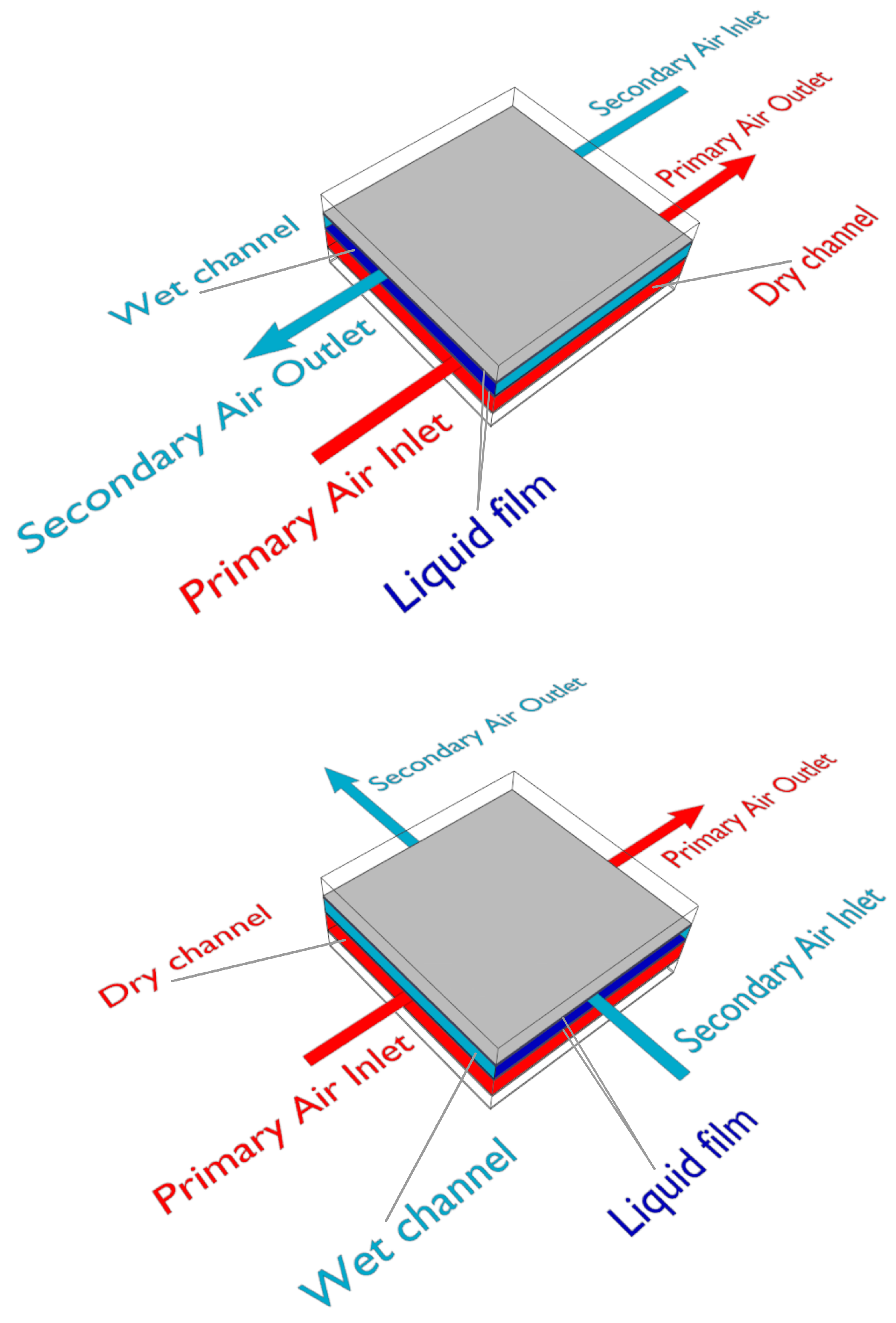
Figure 2.
Scheme of two channels of counter-flow DIEC systems based on the single-stage (top) and multi-stage (bottom) M-cycle.
Figure 2.
Scheme of two channels of counter-flow DIEC systems based on the single-stage (top) and multi-stage (bottom) M-cycle.

Figure 3.
Summary of the types of models analyzed (top-left), numerical schemes used for discretization (top-right), software used for numerical calculations (bottom-left), and validation methods (bottom-right).
Figure 3.
Summary of the types of models analyzed (top-left), numerical schemes used for discretization (top-right), software used for numerical calculations (bottom-left), and validation methods (bottom-right).


Table 1.
Summary of the analytical models for IEC systems.
| Paper | Type of IEC System | Innovations and Advantages | Validation | Possible Limitations |
|---|---|---|---|---|
| Alonso et al. (1998) [25] | All | Equivalence between an infinitesimal element of a IEC system and a complete heat exchanger; definition of an equivalent temperature | Experimental from literature | Assumptions of steady flow with constant air density, and surface wettability factor equal to one |
| Stoitchkov and Dimitrov (1998) [26] | Cross-flow | Estimation of the mean surface water temperature; consideration of the barometric pressure | Numerical from the authors | Model suitable only for cross-flow IEC systems with a flowing down water film; assumption of uniform flow velocities |
| Ren and Yang (2006) [28] | Parallel-flow and Counter-flow | Non-unitary Lewis number and wettability factor; consideration of spray water evaporation, temperature changes, and enthalpy variations | Numerical from the authors | Not suitable for cross-flow IEC systems |
| Heidarinejad and Bozorgmehr (2007) [29] | All | Simplification assuming isothermal plate wall, water film, and air/water interface | Experimental from literature | Implicit assumption of uniformly wetted surface |
| Hasan (2012) [30] | Parallel-flow and Counter-flow | Linear saturation temperature-enthalpy relation; redefinition of potential gradients, heat capacity rate parameters, and transfer coefficient | Experimental from literature | Assumption of unitary wettability factor; non-consideration of cross-flow IEC systems |
| Liu et al. (2013) [31] | All | Iterative estimation of the enthalpy change/temperature change ratio in the wet channels | Experimental from literature | Assumptions of steady flows with constant air density, and unitary wettability factor |
| Cui et al. (2014) [32] | All | Introduction of enthalpy/wet bulb temperature ratio, of a modified overall heat transfer coefficient, and of a driving-force based on the wet-bulb temperature | Experimental from literature | Assumption of unitary wettability factor |
| Chen et al. (2015) [33] | Counter-flow | Consideration of the possible condensation in the dry channels | Numerical and experimental from literature | Assumption of unitary wettability factor; non-consideration of parallel-flow and cross-flow configurations |
| Heidarinejad and Moshari (2015) [34] | All | Consideration of longitudinal heat conduction and the change of water temperature along the plates surfaces in cross-flow configuration | Experimental from literature | Assumption of constant air density |
| De Antonellis et al. (2017) [35,36] | All | Consideration of the adiabatic cooling of the working air in the inlet plenum and of the wettability of the plates | Experimental from the authors | Same heat exchanger and similar working conditions for calibration and validation |
| Moshari and Heidarinejad (2017) [37] | Counter-flow and Cross-flow | Evaluation of the impact of different fin heights on the pressure drops and, consequently, on the power consumption | Experimental from literature | Assumption of unitary wettability factor |
| Comino et al. (2018) [38] | All | Consideration of the effects of variable water flow rate | Experimental from the authors | Same heat exchanger and similar working conditions for calibration and validation |
| Zheng et al. (2019) [39] | Cross-flow | Consideration of the thermal resistance of the condensate film | Experimental from the authors | Assumption of unitary wettability factor |
Table 2.
Summary of the numerical models for IEC systems.
| Paper | Type of IEC System | Numerical Method | Innovations and Advantages | Validation | Possible Limitations |
|---|---|---|---|---|---|
| Wan et al. (2017) [40] | Counter-flow | FVM | Use of a 2-D numerical CFD model to improve the accuracy of a 1-D analytical model | Numerical from literature | Assumptions of constant air density and unitary wettability factor; non-consideration of parallel-flow and cross-flow configurations |
| You et al. (2019) [41] | Cross-flow | FVM | Use of a CFD model to evaluate the influence of some design parameters on the performance of cross-flow IEC systems | Experimental from the authors | Assumptions of constant air density and unitary wettability factor; non-consideration of parallel-flow and counter-flow configurations |
| Min et al. (2019) [42] | Cross-flow | FDM | Use of a numerical model for a performance comparison between counter-flow and cross-flow IEC systems and an optimization of the geometrical parameters | Numerical and experimental from literature | Assumptions of constant air density, and unitary wettability factor; non-consideration of parallel-flow and counter flow configurations |
| Wan et al. (2020) [43] | Counter-flow | FEM | Use of a CFD model to conduct a single-factor and a multiple-factor analysis on the design parameters to improve the correlations for the mean heat and mass transfer coefficients | Experimental from literature | Assumptions of constant air density and unitary wettability factor; non-consideration of parallel-flow and cross-flow configurations |
| Guo et al. (2020) [44] | Cross-flow | FDM | Evaluation of the effect of the condensation area ratio on the IEC system performance | Experimental from the authors | Assumption of unitary wettability factor; non-consideration of parallel-flow and counter-flow configurations |
| Adam et al. (2021) [45] | Cross-flow | RK4 | Use of a numerical model to evaluate the effects of the wettability factor on the IEC system effectiveness | Experimental from literature | Non-consideration of parallel-flow and counter-flow configurations; wettability factor calculation based on the results of an empirical model |
| Shi et al. (2022) [46] | Cross-flow | FEM | Consideration of the non-uniformity in temperature and humidity along the channel width | Numerical and experimental from literature | Assumptions of constant air density and unitary wettability factor; non-consideration of parallel-flow and counter-flow configurations |
| Adam et al. (2022) [47] | Cross-flow | RK4 | Use of a numerical model to evaluate the effects of different condensation states in a cross-flow IEC system | Numerical and experimental from literature | Not specified wettability factor in the validation; non-consideration of parallel-flow and counter-flow configurations |
| Pacak et al. (2023) [48] | Counter-flow | FVM | Use of a CFD model to evaluate the pressure drop along the dry channel of a counter-flow IEC system | Experimental from the manufacturer | Implicit assumption of unitary wettability factor; non-consideration of parallel-flow and cross-flow configurations |
| Adam et al. (2023) [49] | Counter-flow | FVM | Use of an unsteady 2-D CFD model to analyze the influence of the plates shape on the performance of counter-flow IEC systems | Nusselt film empirical formula | Validation of water film thickness only; non-consideration of parallel-flow and cross-flow configurations |
| Ma et al. (2023) [50] | Cross-flow | FVM | Consideration of water spray configuration and water film distribution in the performance analysis | Experimental from literature, Nusselt film empirical formula, and experimental from the authors | Non-consideration of parallel flow and counter-flow configurations |
Table 3.
Summary of the numerical models for DIEC systems.
| Paper | Type of DIEC System | Numerical Method | Innovations and Advantages | Validation | Possible Limitations |
|---|---|---|---|---|---|
| Zhao et al. (2008) [65] | Counter-flow | FVM | Use of a numerical model for the evaluation of the suitability of DIEC systems in hot and dry regions | Not performed | Assumptions of unitary wettability factor and constant air density; absence of validation |
| Riangvilaikul and Kumar (2010) [66] | Counter-flow | FDM | Use of a numerical model to evaluate the influence of the inlet air temperature and humidity on the dew-point effectiveness of a DIEC system | Experimental from the authors and from literature | Assumption of unitary wettability factor |
| Zhan et al. (2011) [67] | Cross-flow | FEM | Use of a numerical model for the performance analysis of a cross-flow DIEC system | Experimental from literature | Assumption of unitary wettability factor and constant air density; not-suitable for counter-flow configuration in this form |
| Cui et al. (2014) [68] | Counter-flow | FVM | Use of a CFD model to evaluate the influence of the design parameters on the performance of a new type of DIEC system with separate product air and working air | Experimental from literature | Assumptions of unitary wettability factor and constant air density |
| Anisimov et al. (2014–2016) [69,70,71,72,73] | All | RKM | Description of the air streams mixing process and of the complete conduction equations for the finned surface | Experimental from literature | Assumptions of constant air density and unitary wettability factor |
| Jafarian et al. (2017) [74] | Counter-flow | FVM | Introduction of a new thermal boundary condition which better reflects reality | Experimental from literature | Assumptions of constant air density and unitary wettability factor |
| Wan et al. (2018) [75,76,77] | Counter-flow | FEM | Use of a CFD model for the evaluation of the heat and mass transfer coefficients and dimensionless numbers in a DIEC system | Experimental from the authors | Assumptions of constant air density and unitary wettability factor |
| Pakari and Ghani (2019) [78,79] | Counter-flow | FEM | Use of CFD regression models for the performance prediction of DIEC systems | Experimental from the authors | Assumptions of constant air density and unitary wettability factor |
| Liu et al. (2019) [80] | Counter-flow | FEM | Coupling of the heat and mass transfer equations with the energy equation | Experimental from literature | Assumption of unitary wettability factor |
| Comino et al. (2022) [81] | Counter-flow | FEM | Use of a modified -NTU numerical model for the optimization of a DIEC system | Experimental from the authors | Assumption of constant wettability factor |
| Zhu et al. (2023) [82] | Counter-flow | FEM | Evaluation of the effects of a non-uniform water distribution along the DIEC system plates | Numerical and experimental from literature | Assumption of unitary wettability factor |
Disclaimer/Publisher’s Note: The statements, opinions and data contained in all publications are solely those of the individual author(s) and contributor(s) and not of MDPI and/or the editor(s). MDPI and/or the editor(s) disclaim responsibility for any injury to people or property resulting from any ideas, methods, instructions or products referred to in the content. |
© 2023 by the authors. Licensee MDPI, Basel, Switzerland. This article is an open access article distributed under the terms and conditions of the Creative Commons Attribution (CC BY) license (https://creativecommons.org/licenses/by/4.0/).
Share and Cite
MDPI and ACS Style
Caruana, R.; De Antonellis, S.; Marocco, L.; Guilizzoni, M. Modeling of Indirect Evaporative Cooling Systems: A Review. Fluids 2023, 8, 303. https://doi.org/10.3390/fluids8110303
AMA Style
Caruana R, De Antonellis S, Marocco L, Guilizzoni M. Modeling of Indirect Evaporative Cooling Systems: A Review. Fluids. 2023; 8(11):303. https://doi.org/10.3390/fluids8110303
Chicago/Turabian StyleCaruana, Roberta, Stefano De Antonellis, Luca Marocco, and Manfredo Guilizzoni. 2023. "Modeling of Indirect Evaporative Cooling Systems: A Review" Fluids 8, no. 11: 303. https://doi.org/10.3390/fluids8110303