1. Introduction
Liquid composite molding (LCM) techniques are innovative and have great capability to produce economical and outstanding components. Moreover, these processes enable the manufacturing of complex and flexible parts [
1]. Among these important processes, liquid resin infusion (LRI) stands out [
2]. The LRI comprises the infusion of a resin by means of injection channels arranged on a domain with a fibrous medium, facilitating resin impregnation along the mold domain [
2]. The important aspects of the LRI processes are the infusion efficiency related to the injection time, costs and quality of the produced parts. Therefore, the configuration of the injection channels has a great impact on the resin flow pattern and, consequently, on the mold filling time and formation of voids in the manufactured components [
1,
3,
4,
5].
Important developments have been made in the numerical realm to improve the understanding of resin transport and void formation in LCM processes [
6,
7]. Numerical simulation is a promising methodology to obtain recommendations for the definition of parameters and design in LRI processes. The resin flow pattern can be predicted early by reducing the possibility of defects in the impregnation process, such as dry spots and the inclusion of bubbles of air, which are detrimental to product quality. Regardless of the strategy used to define the parameters of LCM processes, computational methods can be used to guide the decision maker about the best strategies of design and parameter definition, avoiding critical problems and reducing process costs. More precisely, this methodology is being used to predict pressure distribution, resin flow patterns and void formations. With this information, some process parameters can be optimized, e.g., the distribution of injection channels in the porous domain and the location of resin entry and exit ports. Therefore, the influence of the geometrical configuration of channels on the performance and quality parameters, such as mold filling time, resin waste and generation of dry regions, has also been investigated [
1,
3,
4,
8].
The deployment of numerical approaches for the prediction of LCM processes has been widely explored in various studies [
1,
9,
10,
11,
12,
13,
14,
15,
16,
17,
18,
19]. For example, Pierce et al. [
12] developed a computational model to estimate resin infusion considering the permeability heterogeneities along the preform and tissue deformation. The obtained results were compared with those achieved using more simplified models used in the industry (where tissue deformation is not considered). The authors noticed that the use of combined preform deformation and permeability-dependent properties to predict resin flow along the complex mold resulted in a more realistic behavior, particularly in areas of high shear strain. Later, Shevtsov et al. [
14,
15] performed a numerical study to model and optimize the quality of the infusion, specifically seeking to predict and adequately mitigate the dry spot formation in the fabrication of three-dimensional parts with complex geometries, such as aircraft panels. These works also presented experimental results, demonstrating the formation of dry spots in large panels of aircraft and seeking the causes of the defect’s emergence. The computational method simulated a two-phase flow of resin in a porous preform associated with the equation of Richards (used to model fluid movement in unsaturated soils) to improve the description of porosity and saturation of the preform as a function of pressure. Shevtsov et al. [
15] used a supplemental approach considering thermal, kinetic and rheological effects to predict a vacuum infusion process in a complex 3D geometry. In a study by Gajjar et al. [
16], the vacuum infusion process (VIP) was applied to manufacture flat plates from carbon fiber-reinforced polymers. In this process, the part’s thickness and resin pressure were the main processing parameters. The compaction pressure and volume fraction were measured experimentally at different locations of the flat plate during the manufacturing process, with the former variable compared with the numerical predictions obtained using FLUENT software, version 14. The experimental and numerical results indicate good agreement for the prediction of pressure in the resin along the flat plate. Moreover, it was noticed that the thickness of the part decreased while the volume fraction increased from the resin inlet towards the outlet sections of the domain. A computational model to determine the vacuum-assisted resin transfer molding (VARTM) process with high-permeability reinforcements was developed by Adhikari et al. [
17]. This kind of reinforcement brings additional complexity to the approach. Then, the authors proposed a novel depth-averaged technique to represent, in a more suitable form, resin flow advances in high-permeability media. The new model considered spatial and temporal variations in the compaction of the preform and flow in the transverse direction of the reinforcement. Recently, Li et al. [
18] developed a computational method to consider two-phase flows of resin in the inter- and intra-fiber tow regions. The Navier–Stokes equations are solved in the region of free flow, whereas the tracking of the flow front of the resin is modeled using the Cahn–Hilliard equation. Ouezgan et al. [
19] performed a numerical investigation to identify strategies for manufacturing routes that improve parameters such as resin pressure distribution and infusion time. The authors verified that the strategy of resin injection preceding the vacuum step reduced the infusion time in the fibrous medium.
Despite the several important works above mentioned, an investigation of the geometry influence of injection channels over the mixture fluid flow of resin and air in a porous medium has been not sufficiently explored in the literature. In this subject, Magalhães et al. [
20,
21] applied constructal design [
22,
23,
24,
25,
26] to investigate the influence of the injection channels geometry on mold filling time. I- and T-shaped channels were positioned inside a squared reinforced medium and flow advance inside mold cavity was monitored during the injection process. For the investigated conditions, the optimal T-shaped configuration improved the process performance almost three times compared to the best one found for I-shaped channel. In the present study, a methodology was employed in which the geometric configuration of the injection channels grows from an elementary construction using a control function based on flow resistance. More precisely, the present study investigates the influence of the injection channels construction on the performance indicators of the system, such as resin filling time to impregnate the entire porous domain and the mass of resin wasted in the resin infusion process. Two different strategies of construction were also compared: assembling each new empty channel element in the position with the lowest flow resistance and inserting a new element in the position with the highest flow resistance. The algorithm for the growth of empty channels follows the constructal theory. The application of constructal theory for generating configurations of injection channels inserted into a porous medium has not been explored in the literature. According to Bejan [
22], constructal theory is a visualization where the geometric configurations and patterns of finite-size flow systems are guided by a physical principle (constructal law). This law states that, to ensure life conditions for the finite-size flow system, its design must evolve with freedom to facilitate access to internal currents [
23,
24,
25,
26]. Constructal theory has been used to explain the formation of design in various problems, e.g., social dynamics [
27]; thermal systems, specifically heat exchangers [
28,
29]; renewable energy sources [
30], and even solid mechanics [
31,
32].
The methodology proposed here is similar to that investigated in previous works of Refs. [
33,
34]. Vianna et al. [
33] used constructal theory to obtain the geometry of a cooling cavity inserted into a solid wall with heat generation. The cavity grows from an elementary shape, called the elemental constructal (EC). This growth is guided by a construction function that defines each new placement of the cavity, up to a limit defined by the occupation area of the cavity. This approach is dissimilar to that performed in the previous works, where pre-defined configurations (e.g., I, T, Y, and X) were investigated, see Ref. [
35]. The main purpose of the study of Vianna et al. [
33] was to improve the comprehension of the evolution (growth) of the cavity that minimizes the maximum temperature in the solid domain. In addition, the cavity growth problem was used as an illustration of a more general methodology used to determine how the shape and structure of flow systems can evolve. Recently, Pedroti et al. [
34] applied the same methodology in another physical problem, developing a tubular array of tubes without the use of any initial predefined arrangement, being constructed from an elementary configuration (with one tube). In this investigation, the fluid dynamic and thermal fields were used to define a placement function. The maximum magnitude of this function is used to define the position for the insertion of each new tube inside a finite-size occupation area. The foundation for the construction of each new element and use of a construction function used in the present work was based on these previous studies.
In the present work, a strategy similar to the one investigated in Ref. [
33] was used to build empty channels inserted in a porous squared plate. The process begins with an elementary construction involving only one square empty channel. Even a problem involving a low-resistance pathway (empty channel) inserted in a high-resistance background (porous plate) was investigated here. The formation of the high-resistance empty channels may differ from that found in cavities due, for example, to the formation of voids in the domain. Consequently, the design of the empty channel can not be merely copied from the cavity problem. It is also worth noting that the LRI process is only a motivation for the present investigation, the main contributions here being the clear definition of the construction function that easily describes the flow access and guides the design according to constructal theory; additionally, the application of this method to a new physical problem where the methodology has not yet been investigated. In this sense, some idealizations were employed in the present problem to make the investigation viable, e.g., the use of a square two-dimensional plate, the use of large channels in comparison with the plate size, large inlet size in comparison with real conditions, and free outlet exits to accelerate the construction process. Such assumptions are valid here since the present study is based on the proof of concept. Then, if the methodology worked for the simplified method, it can be attempted and adapted for a more real complex part. To the best of the author’s knowledge, the proposed methodology applied to comprehend the influence of the form of empty channels in the resin flow advance through a reinforced porous medium has not been presented before in the literature.
2. Mathematical Modeling
The solution of laminar, unsteady, and incompressible flows of the mixture of resin and air in a two-dimensional problem was obtained with a computational model that uses the finite volume method (FVM) for the discretization of differential equations and the volume of fluid (VOF) for the definition of the two immiscible phases of resin and air. The computational fluid dynamics (CFD) commercial code FLUENT, version 14, was employed in the simulations [
36]. It is worth mentioning that in the consideration of Newtonian fluid, incompressible and laminar flows have been widely used to simulate different LRI processes, see Refs. [
1,
2,
9,
20].
The continuity equation and balance of momentum for the mixture of resin and air considered in the present problem are given by [
37]:
where
ρ is the density of the mixture (kg/m
3),
is the velocity in the fluid (m/s),
P is the pressure (Pa),
t is the time (s),
is the gravitational field acceleration vector (m/s
2),
is a body force of the porous medium resistance to the resin flow (N/m
3). The fluid stress tensor (N/m
2) is defined as:
where
μ is the dynamic viscosity of the mixture (kg/(m∙s)). Once the flow is considered incompressible, the bulk viscosity (
λ) and deviatoric stress tensor are disregarded here.
To represent the body force of the porous medium in the mixture flow, Darcy’s law is used [
37,
38,
39]:
where
K is the porous medium permeability (m
2).
The definition of regions of air and resin in the multiphase flow is performed with the VOF model [
40]. In this model, the following transport equation for the resin volume fraction (
f) is solved [
40]:
where
is the velocity field predicted with Equation (2).
With the calculation of volume fraction, density and dynamic viscosity of the mixture in each computational domain cell can be determined by [
41]:
2.1. Description of the Physical Problem
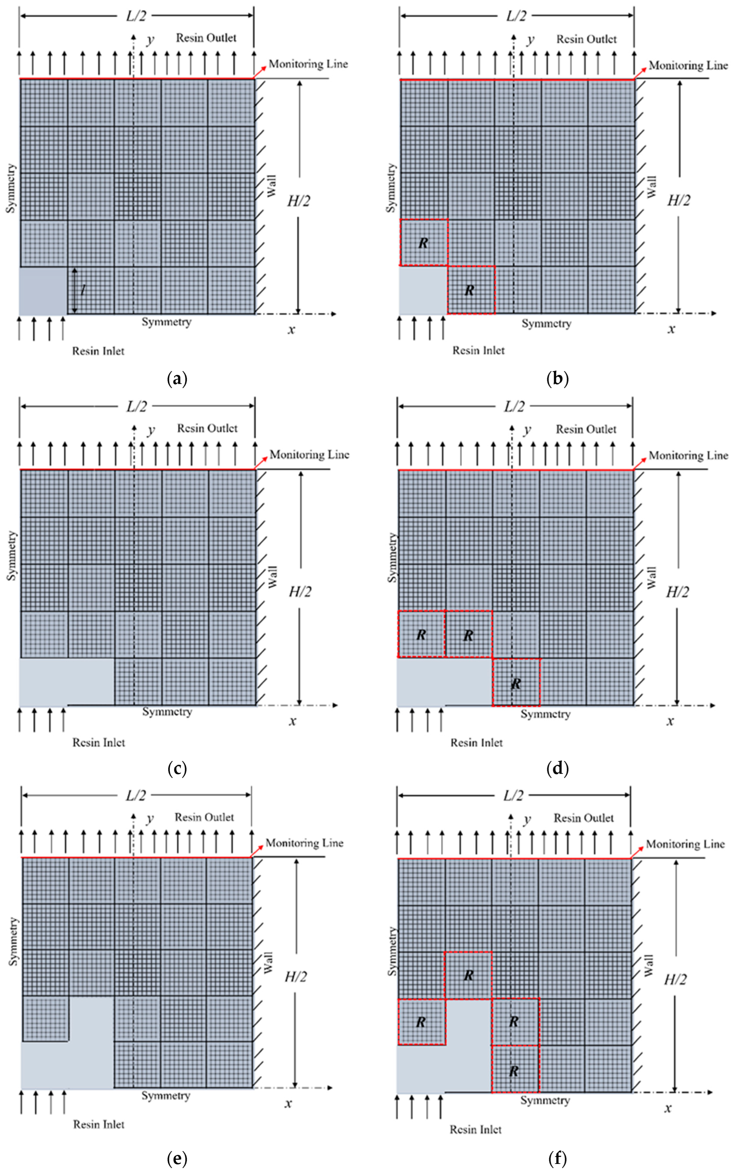
The present problem consists of inserting empty channels along one rectangular plate with a porous medium, mimicking a LRI process, as can be seen in
Figure 1. The simulation represents an idealized resin flow in channels placed on the top of the porous domain. Resin flow is generated by the pressure difference imposed at the resin inlet (inferior region of the channel) and the outlet.
Figure 1 illustrates one-fourth of a porous plate domain simulated here with the inlet of resin being performed in the center of the domain; thus, for the case of the complete domain, the entry of resin takes place in the central region. In
Figure 1, the empty channel (elementary construction of the channel) is illustrated with a light gray color, while the porous domain is characterized by the dashed gray region.
Concerning the growth of the empty channel, the plate domain is shared in several imaginary small squares where empty channels can be mounted.
Figure 1 illustrates a domain with 5 × 5 divisions where the new empty channels can be positioned. These regions do not have a relation with the spatial discretization for the CFD fluid flow solution. Despite that, the grid lines in the porous domain of
Figure 1 illustrate the CFD mesh composed of rectangular volumes used in the numerical simulations. The mesh is also employed in the empty channel, but it is not depicted in
Figure 1 to prevent confusion regarding the empty channel and the porous regions. The construction begins with an elementary empty channel (
N = 1) placed in the lower-left corner of the plate domain (see light gray region in
Figure 1). Each element mounted in the domain is called here “elemental constructal” (EC) [
33]. The EC dimensions are important for the generation of the empty channels design and it is called here “channel resolution” (CR). The number of mounted ECs and the size of CRs are the degrees of freedom of the present problem. Here, the number of possible positions in the
x and
y directions for the mounting of new ECs and two different magnitudes of CR (CR = 5 and 10) are considered to be the same. As the higher the CR, the smaller the area of each EC, this leads to a greater number of possibilities for assembling the final empty channel design [
33]. It is important to reinforce that this methodology is like that previously studied in the works of Vianna et al. [
33] and Pedroti et al. [
34] for the building of intruded cooling cavities into walls with internal heat generation and cylinder arrangements with forced convective flows, respectively. Here, the methodology is adapted for the construction of the empty channels placed over a plate of porous medium, being investigated as the best strategy for the construction function and the influence of the new physical problem over the construction.
The superior surface of the domain has zero pressure (gauge) imposed and zero derivative of the volume fraction in the flow direction. In the right surface, a non-slip and impermeability condition is imposed (
u =
v = 0 m/s and
df/
dx = 0). At the lower-left surface of the injection EC, a constant pressure of
Pin = 1.0 × 10
5 Pa and volume fraction
f = 1 are imposed, while symmetry boundary conditions are applied in the remaining surfaces. Concerning the thermophysical properties, the following properties were considered for resin and air:
ρresin = 916 kg/m
3,
ρair = 1.225 kg/m
3,
µresin = 0.06 Pa s and
µair = 1.7894 × 10
−5 Pa·s. A permeability of
K = 2.0 × 10
−11 m
2 and a porosity of
ε = 0.50 were used in the porous domain. These properties were previously used in the literature; see [
42].
To obtain the infusion time and the wasted mass of resin along the process, a monitoring line was inserted in the domain exit (
Figure 1) defined by the following points:
P1 (
x1 = −0.125 m;
y1 = 0.25 m) and
P2 (
x2 = 0.125 m;
y2 = 0.25 m). When the volume fraction along the entire line is
f = 1.0, it can be considered that the resin flow has filled the domain, and the infusion process is complete. The mass of wasted resin was calculated as
where
is the instantaneous mass flow rate of the resin, given by [
36]:
where
Vn is the component of the velocity in the normal direction of the cross-sectional area (m/s) and
A is the flow cross-sectional area (m
2). The occurrence of permanent voids in the plate is also verified since the cases with permanent voids are disregarded for construction of the empty channel, given that the domain is not fully impregnated.
In the present work, a comparison is made between the assemblies of new elements (ECs) at placements adjacent to empty channels with the highest or lowest resistance (
Rhigh or
Rlow) to resin flow. Flow resistance is defined as the ratio between the pressure drop (potential difference) and the mass flow rate of two adjacent ECs (horizontal or vertical coordinates), as [
43]:
where Δ
p is the pressure drop between two adjacent EC regions [Pa],
V is the velocity at the center of regions where a new EC can be mounted [m/s],
l is the size of the EC crossed by the resin [m], and
W is the dimension in the
z plane, which in the present work was treated as unitary since the domain is two-dimensional.
2.2. Building the Empty Channels with Constructal Theory
For the empty channels creation analysis using constructal theory, it is required to define the performance indicators of the problem. Here, two performance indicators were analyzed: the filling time for resin impregnation in the entire domain and the mass of resin wasted in the process of impregnating the entire domain. The best shapes are the ones that minimize both performance indicators. The growth of empty channels from an elementary construction was performed with the use of a control function based on the resin flow resistance, Equation (10). In other words, we did not use a pre-defined configuration (I, T, Y, or other) for the empty channel, but instead constructed from an elementary configuration. This also established the operational parameters and the problem geometrical constraints.
The present problem is subject to two constraints. The first one is the plate domain area, given by:
and the fraction area of the injection channel (ratio between open channel and plate areas), which is given by:
where
A is the total area of the porous plate [m
2],
H is the porous plate height [m],
L is the porous plate length [m], and
A0 is the area of the empty channel [m
2]. In the present investigations, it is considered a square plate (
H =
L = 0.5 m) for all cases characterizing a constant ratio
H/
L = 1.0.
The proposed methodology for the empty channels’ construction, from an elementary configuration to the most complex configuration, can be schematically seen in
Figure 2. After defining the first case with the elementary injection channel (first EC),
Figure 2a, a numerical simulation was performed to find the fluid dynamic fields, as well as the performance indicators. Then, the resin flow resistance was calculated in the adjacent square domains,
Figure 2b, where a new EC could be positioned. The region with the
Rlow (in the case of mounting in regions of
Rlow) was chosen to be the position where a new EC was mounted. It is worth noting that the resistance was calculated between the center of one empty EC and the center of the nearest EC in the porous medium. Then, this EC was changed from a porous medium element to an empty channel element,
Figure 2c, leading to the first growing of the empty channel. After the definition of the new domain, a new simulation was performed, and the fluid dynamic field was calculated for the new domain. From this field, the resin flow resistance was calculated for the new configuration,
Figure 2d, and another position for insertion of a new injection channel was defined,
Figure 2e, representing a second step of empty channel growing. This procedure is repeated several times,
Figure 2f, until the empty channel reached a maximum occupancy area (
ϕmax). The resistance was calculated here when the resin for each growth step was completely impregnated in the porous domain. Here, the construction was interrupted when the newly generated empty channel led to permanent void formations on the plate. Furthermore, in the present work, only one element was assembled per growth stage. For each growth step, performance indicators (filling time and wasted resin mass) were calculated to investigate how the growth of the empty channel was configured and how it affects the performance of the problem. It is also worth mentioning that only one numerical simulation was performed for each construction step. Therefore, it is a fast method of construction.
The proposed construction methodology can be summarized with the following algorithm (adapted from Vianna et al. [
33]):
- (1)
Define the problem domain and boundary conditions;
- (2)
Define the placement of the first empty channel;
- (3)
Obtain numerically the fluid flow solution for the problem, as well as the performance indicators (filling time and wasted mass of resin);
- (4)
Calculate the resin flow resistance in the square domains adjacent to the existing injection channel when the resin is completely impregnated in the porous domain;
- (5)
Replace the EC, with less resistance to flow (in the case of minimizing resin flow resistance) with an empty channel;
- (6)
Define the new domain with a new injection channel;
- (7)
Return to step 3 and repeat the steps until the empty channel reaches the limit established by the occupancy area (ϕmax) or leads to the generation of permanent voids.
To investigate the influence of the EC resolution over the empty channel construction as well as the problem performance, two different values of CR were analyzed (CR = 5 and 10). The construction of the channels was restricted to a maximum occupation area of ϕmax = 0.2, which is known to be a very large value, not used in real industrial application but suitable for the proposed study. Smaller values of ϕmax would require using larger CRs, resulting in larger simulation times with small (maybe none) contributions to the goals of the current study. The upper portion of the porous plate was also restricted to the occupation of empty channels to avoid large magnitudes of wasted resin. More precisely, the ECs adjacent to the upper boundary (outlet) of the board were not considered for the occupation of the empty channel. At each growth step, the area of the channel increased by the ratio 1/25 and 1/100 of its magnitude for CR = 5 and 10, respectively, compared to the first elementary construction case (since it was considered a symmetry condition of the mold and only a quarter of the domain was simulated). For the cases of CR = 5 and 10, 5 and 20 steps, respectively, were needed to build the resin infusion channel considering the maximum occupancy area established. Therefore, a total of 50 simulations were performed in the present investigation.
3. Numerical Approach
The FVM was used for the numerical solution of Equations (1)–(5) [
44,
45]. More precisely, it was employed using the commercial code FLUENT, version 14 [
36]. To tackle the coupling between the pressure and velocity fields, the PISO method was used. Moreover, the interface delimitation between the resin and air was solved with the Geo-Reconstruction method. The convergence for each time-step advancement was obtained when the residuals were lower than
Res < 10
−6. The simulations are performed in a computer with a processor Intel(R) Core(TM) i7-5930K CPU @ 3.50GHz and 16 GB of RAM memory. A variable time step in the range 10
−3 s ≤ Δ
t ≤ 1.0 s was applied. The maximum Courant number in the interface was used to define the magnitude of the time step. In this case, the maximum Courant number equal to 0.25 was used. Concerning the mesh used, the domain was divided in several rectangular finite volumes. Additionally, a mesh independence study was performed to define the number of finite volumes used in all simulations.
The created mesh was regular, with rectangular volumes, and each EC was discretized with
nR ×
nR finite volumes, where
nR is the division of an EC in the rectangular finite volumes.
Table 1 shows the number of divisions in each EC (
nR), the number of volumes of discretization in the whole domain, the filling time for the resin injection in the domain, and the difference between two successive solutions (spatial discretization). The chosen problem to check the mesh independence was the case with empty channel composed of only one EC (
N = 1), i.e., the most elementary construction. The grid was considered independent when the relative difference between the injection time obtained for two successive grids complied with a mesh refinement criterion, which was given by:
where
tj represents the injection time value calculated with the coarsest mesh and
tj+1 corresponds to the calculated value with a refined mesh. Besides the criterion described in Equation (13), we also analyzed the mold filling quality. For the cases with
nR < 8, the generation of permanent voids was noticed. Therefore, despite achieving the established criterion in Equation (13), these cases were disregarded once they led to the generation of empty spaces, which is a critical problem in the LRI process. In this sense, a grid with 2500 finite volumes was chosen as the independent one.
With the purpose to verify the present numerical model, a resin flow in a rectilinear porous medium and one-dimensional direction was compared with the analytical solutions presented in the works of Rudd [
38] and Jinlian et al. [
46]. More precisely, we compared the placement of the resin front line as a function of the time for a constant injection pressure (
P0 = 200 kPa), the permeability of the medium (
K = 1.0 × 10
−10 m
2), and a dynamic viscosity (
μ = 0.01 Pa·s). The results of the analytical solution and that obtained with the present computational model are presented in
Table 2, showing the accuracy of the present model for the simulation of resin flow in a porous medium.
4. Results and Discussion
A comparison was made between the assembly of new ECs at points adjacent to the empty channels with Rhigh or Rlow to resin flow. For both constructions, the resin flow resistance is defined by Equation (10). The influence of construction for Rhigh or Rlow on the geometric configuration of the empty channels, as well as the performance indicators of the system (resin filling time for impregnation throughout the porous domain and the mass of resin that was wasted in the resin infusion process), was investigated.
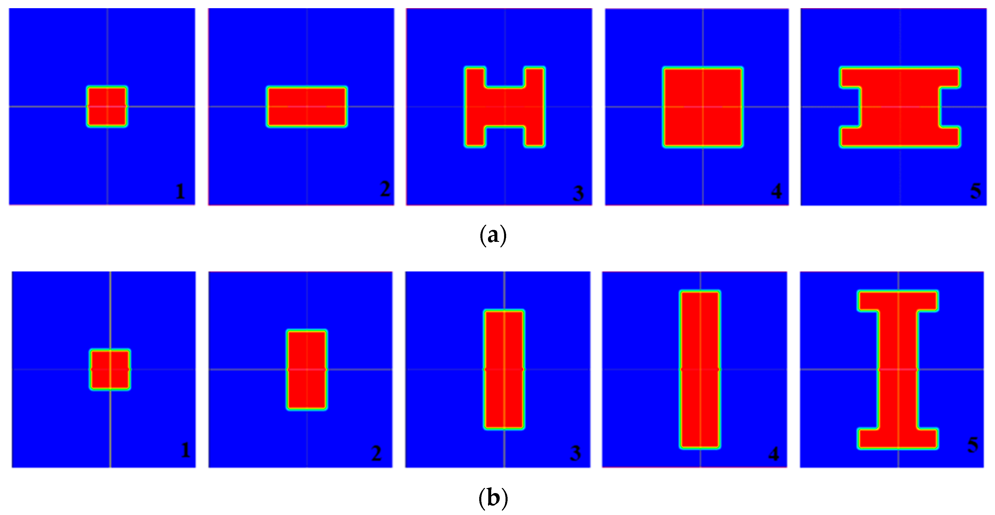
Figure 3 shows the geometric configurations at each growth stage of the injection channel for CR = 5. Here, five elements were mounted with empty channels along the simulated domain, considering the restriction of maximum area fraction. It is important to reinforce that the entire plate is being presented, obtained by mirroring the quarter computational domain. The same presentation is performed for all fields depicted from this point onward.
Figure 3a illustrates the mounting of the empty channel in the ECs of
Rlow for each step of construction, while
Figure 3b depicts the mounting of new elements of the channel with the
Rhigh, which does not comply with the constructal theory. The red color in
Figure 3 illustrates the empty channel filled with resin for each step of construction and the blue color represents the fibrous region to be impregnated with resin.
Figure 3a shows that the insertion of new elements in the regions of
Rlow led to configurations increasing in the
x direction of the domain (
N = 2) followed by an H configuration for
N = 3, a square configuration for
N = 4, and a transverse H-shaped configuration for
N = 5.
Figure 3b shows that the construction of new ECs in regions of
Rhigh conducted had dominant growth in the
y direction (in the direction of the outlet section) until
N = 5. For the last case, the local restriction for mounting new elements in the vicinity of outlet line avoids a new construction in the
y direction, leading to the generation of a transverse H-shaped configuration. The results of
Figure 3 indicate that the consideration of the mounting of new ECs in regions of
Rhigh or
Rlow affected the construction of the empty channel.
Figure 4 and
Figure 5 illustrate the effect of the number of empty channels inserted on the filling time (
t) for resin impregnation in the porous domain and the amount of resin mass (
m) wasted in the process for CR = 5, respectively, obtained with both studied construction methods. We considered the results to be a growth from the elementary construction (
N = 1) to the maximum number of ECs (
N = 5) limited by the maximum area fraction
ϕmax = 0.2. In general, the results in
Figure 4 and
Figure 5 demonstrate that constructing new empty channels in the regions of
Rlow resin flow led to better results compared to mounting in the regions of
Rhigh for both performance indicators (
t and
m) across all number of ECs inserted in the domain.
In
Figure 4, it can also be observed that the effect of the number of ECs inserted in the domain (
N) on the filling time (
t) exhibits a similar behavior for both construction strategies, with an advantage of nearly 40% for
N = 5 when the
Rlow was used to construct the arrangement of empty channels. In
Figure 5, the effect of
N over
m also varies for different construction strategies of the arrangement of the empty channels. For
N = 5, the magnitude of wasted mass of resin for the construction in the regions of
Rhigh is almost 25 times superior to that reached for the construction in regions of the
Rlow. This behavior can be explained by the configurations seen in
Figure 3, where the empty channels increased in the direction of the outlet surface, leading to a strong variation in the frontal line of the resin in the
y direction of the domain, while the resin flow had a low insertion in the
x direction.
Figure 6 illustrates the advance of the resin front line in the porous medium for
N = 5 and
ϕ = 0.2 when the mounting was performed in the regions of
Rlow,
Figure 6a, and
Rhigh,
Figure 6b. Three different instants of time are presented (
t = 30 s, 90 s and 190 s) to illustrate the advancement of resin flow for the two different configurations obtained with the two investigated strategies of construction. The constructed channels are identified with the continuous lines inside the red region.
In
Figure 6, it is possible to notice a difference in the direction in which resin advances with more intensity. For the construction based on
Rlow, the mold was completely impregnated in the
x-direction before beingfilled in the
y-direction, while the construction based on
Rhigh led to the contrary pattern. The impregnation behavior observed for the strategy of mounting new elements in the
Rhigh regions explains the excessive increase in wasted mass of resin (
m) with the increase in the number of inserted elements, mainly in the range 2 ≤
N ≤ 4. The results also indicate that there is no important void generated in the porous domain, which would discard the produced piece. In some cases, such as in
Figure 6a at
t = 190 s, it is possible to observe the generation of permanent small voids near the lateral surface. This generation is caused by shear stress in the resin flow front line retaining some air. Despite this fact, this kind of design can be considered valid since the piece can receive a final finishing, preventing any damage to the final component.
To investigate the influence of channel resolution (CR) on the empty channel growth and the performance of the infusion process, a similar study previously carried out for CR = 5 was repeated for CR = 10. For the simulated domain (1/4 of the mold), the plate was divided into 100 squared regions (ECs); two of them were initially occupied with the empty channel to impose the same resin mass flow rate used with the CR = 5 case. Here, it was necessary to assemble nineteen empty ECs for the construction of the resin infusion channel, considering that the maximum occupancy area of the empty channel is ϕmax = 0.2.
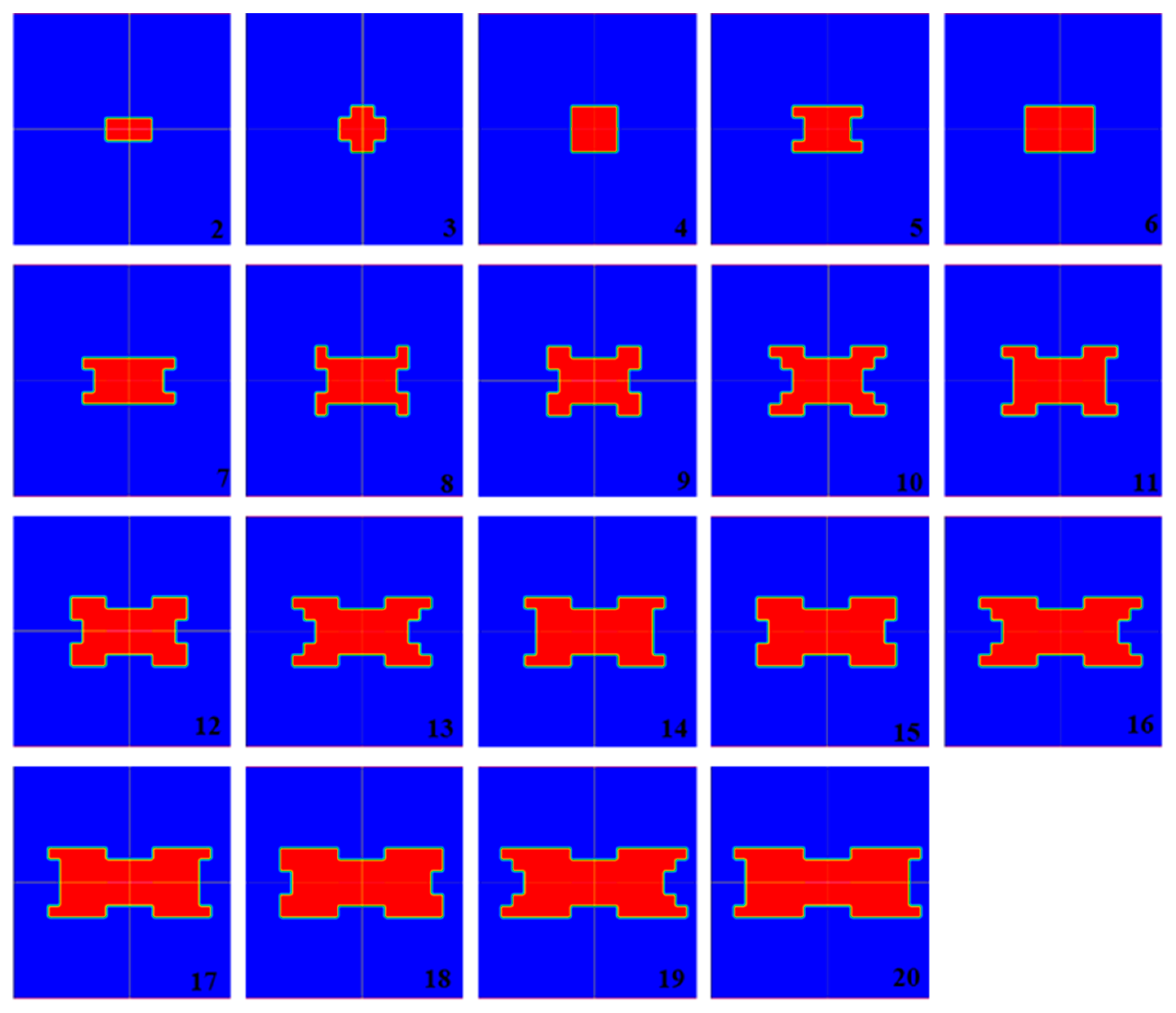
Figure 7 and
Figure 8 show the geometry configurations at each growth stage of the injection channel with CR = 10 for the two different studied construction strategies. In
Figure 7, in terms of geometric construction, the results indicate that ECs mounted in the
Rlow regions increase from the center to the periphery of the porous medium, leading to a final configuration like a X-shaped channel.
Figure 8, on the other hand, shows that the construction of the injection channel with each new EC in the
Rhigh position leads to a circular configuration. Therefore, even using the same control function, the definition of the mounting position of each new EC in the
Rlow or
Rhigh regions strongly influences the geometric configuration of the constructed injection channel.
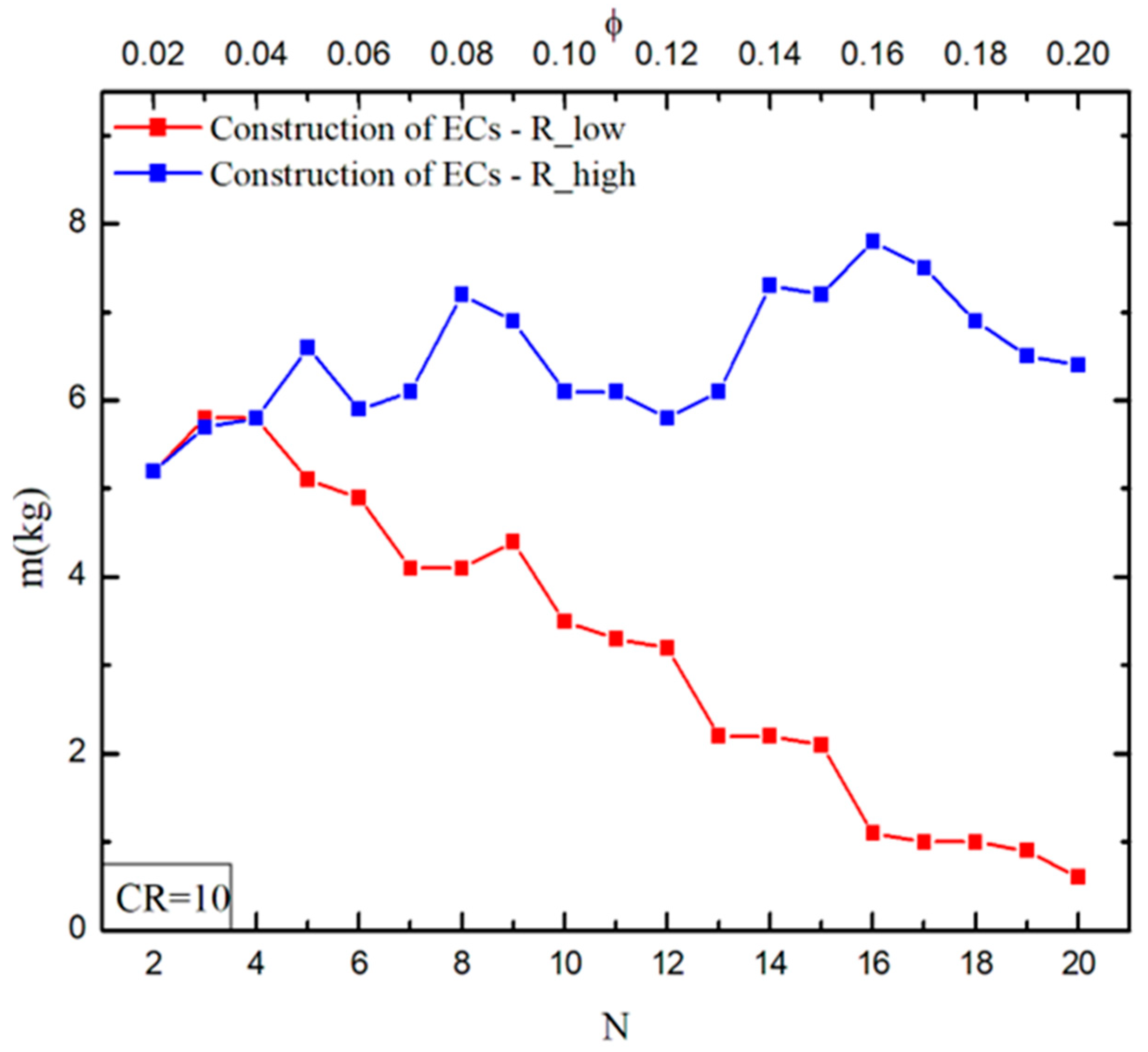
Figure 9 and
Figure 10 show the effect of the number of inserted ECs on the resin injection time and the amount of resin mass wasted in the process, respectively, for CR = 10, obtained with the construction technique in the
Rlow and
Rhigh regions. Analogously to the results obtained for CR = 5,
Figure 9 and
Figure 10 show that, for CR = 10, the control function applied in the
Rlow region led to the best results. In other words, the construction of the injection channel in
Rlow regions led to the best performance for both analyzed performance indicators (
t e
m) in comparison with the construction in
Rhigh regions. Therefore, the results recommend that the construction of the new empty channels in
Rlow regions is the most adequate choice to maximize the performance of the studied problem.
Analyzing the effect of the number of ECs (or magnitude of
ϕ) on the performance indicators, the results in
Figure 9 indicate that, as expected, the injection time is minimized for the largest magnitudes of
N (or
ϕ). In
Figure 10, it is noted that, for the construction technique of mounting the new ECs in the
Rlow region, the best results of
m were obtained for the highest numbers of ECs (
N ≥ 16). On the other hand, for the construction technique where new empty channels are inserted in
Rhigh regions, an oscillation of
m is observed, with the best result being obtained with the most elementary configuration (
N = 2). It is most likely that, the increase in the number of ECs, i.e., the channel resolution (CR) is conducive to the minimization of these oscillations. Therefore, in the present problem, the choice of the correct strategy is important to construct a close-to-optimal injection channels configuration. A comparison between the different resolutions (CR = 5 and 10) shows that the EC sizes have great influence on the fluid dynamics and are a determinant factor for suitable prediction of the injection channels’ geometric configuration. In general, the proposed construction technique seems promising to predict the configuration of empty channels in resin infusion processes.
To illustrate the transient behavior of resin flow in the mold,
Figure 11 shows the distribution of the resin volume fraction as a function of time for the geometric construction with a higher number of ECs,
N = 20 and
ϕ = 0.2, for the two construction strategies. The fields of volume fraction are presented for the following time instants:
t = 30 s, 80 s, and 130 s, respectively. In
Figure 11a it is possible to notice that there is a greater advance of the resin in the
x direction (from the center to the periphery of the porous medium) in comparison to the advance in the
y direction. As the time advances, resin flow becomes practically linear, thereby facilitating the advance of the resin over time. In
Figure 11b, the resin exhibits a radial behavior, resulting in an increased filling time and, more importantly, a significant rise in resin waste.
When comparing the two construction strategies, i.e., the construction of ECs in Rlow regions versus the construction in Rhigh regions, the results for CR = 5 indicate that the Rlow construction led to performances 41.5% and 89% superior on injection time and resin wasted than that obtained with the Rhigh construction. Analyzing the optimal geometries for CR = 10 in both used construction strategies, we observed an improvement of 30.8% in the injection time and 88% in the resin wasted when the construction was performed in adjacent ECs of the Rlow strategy. Thus, the results for the fields of resin volume fraction corroborate that the new injection channels must be inserted in the Rlow regions to maximize the access of resin flow along the porous medium.
Comparing the performance of the studied resolutions, CR = 5 and CR = 10, for the application of the construction technique, it is observed that the effect of CR on the infusion time does not have significant variation. However, the resolution effect in the wasted resin mass is quite influential.
Figure 12 illustrates the optimal configuration found for CR = 5,
Figure 12a, and CR = 10,
Figure 12b, respectively. It is noticed that the best configuration found for CR = 5,
N = 5 or
ϕ = 0.2, illustrated in
Figure 12a, led to a resin waste of
m = 2.77 kg. Meanwhile, the optimal geometry for CR = 10 (
N = 20 or
ϕ = 0.2), depicted in
Figure 12b, led to waste of
m = 0.6 kg, i.e., the system performance was improved by about 361.7% with the increase in domain resolution. It is most probable that the use of more refined resolutions can lead to an increase in performance up to the point where the resolution does not affect the generated configuration anymore. However, increasing the resolution results in a large number of cases to be simulated, as a computational strategy is required to perform the study, which is not the scope of this work.
In present study, the results were more promising for CR = 10 than for CR = 5 due to the increase in freedom to define the design of empty channels. The most complex geometries led to the best performance of the injection process, regardless of the performance indicator. This behavior agrees with the previous observation of Bejan [
23], who noticed that more complex low-resistance pathways complete the invasion of a low-resistance medium before simple low-resistance pathways. In this sense, the results show the importance of geometric evaluation for the liquid resin infusion process. Moreover, the application of the constructal theory to grow the empty channels from an elementary configuration is adequate to predict the configuration of this type of process.
It is important to highlight that this is a theoretical study. Before more complex configurations with higher magnitudes of CRs can be investigated, it is important to define a computational strategy to automate the growth of the empty channel. Even with this limiting condition, it is possible to observe that for higher values of CRs, the flow channel would likely become longer in the
x-direction and shorter in the
y-direction. This solution is close to the well-known (and successful) cavity positioning used for a similar simple geometry in a conducting heat transfer problem [
33]. Therefore, the obtained results strongly indicate that the proposed methodology, which has presented good results in similar problems [
33,
34], may become an important tool to predict channel positioning on more complex (non-obvious) mold geometries using a construction based on a physical principle.


 and
and 


