1. Introduction
Since polyethylene oxide (PEO)-based lithium solid polymer electrolytes (SPEs) were introduced in solid lithium batteries in the late 1970s [
1,
2], much research effort was devoted to the development of high-performance all-solid lithium polymer batteries from the 1980s to the 2000s. However, various issues associated with PEO-based electrolytes have held back the practical realization of all-solid lithium polymer batteries. The weak points of PEO–lithium salt complexes (PEO-LiX) are typically as follows. (1) The conductivity is low in the range of 10
−7 to 10
−8 S/cm at room temperature. Therefore, the cells must be operated at a temperature higher than 60 °C, where the amorphous phase in the PEO–salt complex becomes dominant, which is associated with the high lithium ion conductivity [
3,
4,
5]. (2) High-voltage cathode materials such as LiCoO
2, Li(Ni,Co,Mn)O
2, and LiMn
2O
4 have low reversible capacities in SPE cells [
6,
7], which are assumed to be the result of the low decomposition potential (narrow electrochemical window) of polymer electrolytes compared with that of conventional liquid electrolytes [
8].
However, such a solid polymer has a flexible and deformable character, which enables better mechanical and electrical contact with active electrode materials than that with inorganic solid electrolytes. In addition, the relatively good stability against Li metal [
9] is advantageous compared to inorganic oxide and sulfide solid electrolytes, although the process is prone to lithium dendrite formation under high-current-cell operation [
10,
11,
12]. The good compatibility with graphite as an anode [
13,
14] is also beneficial in comparison to other solid electrolytes.
Efforts to improve the poor low-temperature characteristics of PEO-based electrolytes have been continued by the modification of PEO-based polymers over the past two decades (see cited reviews [
15,
16,
17]); i.e., (1) the appropriate design and selection of easily dissociated lithium salts with a high lithium transference number (
t+) [
18], (2) the addition of plasticizers to facilitate the segmental motion of polymer chains, (3) the dispersion of fine ceramic particles in the PEO matrix to improve the fraction of amorphous phase, and (4) the synthesis of copolymeric, cross-linked, or branched PEO-based polymers with structures suitable for the acceleration of lithium ion hopping.
Over the past decade, various reports aimed at an increase in the performance of SPEs have been published. Although there have been a fair number of reports on studies to improve the stability of so-called 4 V class cathodes and SPEs [
19,
20], sufficient battery properties have not been established as well as with liquid electrolytes. In many cases, 3 V class cathode materials, especially LiFePO
4, have been selected to demonstrate good electrolyte performance in tested cells. No detailed discussions on the decomposition potential for high-voltage cathode materials have been reported.
The 4 V class cathode materials, such as LiCoO
2, LiMn
2O
4, Li (Ni, Co, Mn) O
2, etc., that have been extensively used in liquid electrolyte cells have been known to show much lower reversible capacity in PEO-based electrolyte cells [
6,
7]. In 2001, we reported the cut-off voltage dependence on the capacity vs. cycling number for a Li/PEO
19-Li(CF
3SO
2)
2N (LiTFSI)-10 wt% BaTiO
3/LiNi
0.
8Co
0.
2O
2 cell [
21], where the subscript 19 indicates that the molar ratio of Li salt to the oxygen in PEO(Li/O = 1/19). The cell capacity decreased rapidly with cycling by charging up to 4.0 V and discharging to 2.5 V. On the other hand, no significant capacity fade was observed by charging up to 3.9 V or less. Aihara et al. reported 500 charge–discharge cycles with 100% capacity retention in the operating range of 3.0–4.1 V for Li/LiCoO
2 cells with an SPE modified from PEO [
22]. Judging from the reports on polymer electrolyte cells, the decomposition potential of PEO-related electrolytes can be estimated to be in the range from 3.7 V to 4.1 V [
8,
9].
The research group of the Central Research Institute of Electric Power Industry, Japan, succeeded in the relatively stable cycling of a Li/PEO-based SPE/LiCoO
2 cell up to 4.6 V vs. Li/Li
+ (better cyclability was obtained at less than 4.4 V vs. Li/Li
+) by interposing Li
3PO
4 between the polymer electrolyte and LiCoO
2 [
23,
24]. Our group reported the cycle test of a Li/[(PEO–10 wt% HBP)
10(LiTFSI–10 wt%LiPF
6)]–10 wt%BaTiO
3/LiNi
0.8Co
0.2O
2/Al cell, where HBP (hyperbranched polymer poly[bis(triethyleneglycol)benzoate] capped with an acetyl group) and BaTiO
3 were added to enhance the conductivity of the SPE. The addition of 10 wt% LiPF
6 to LiTFSI increased the cycle performance significantly. The initial cathode capacity of 150 mAh/g declined to 74 mAh/g after 410 charge–discharge cycles at 0.57 C with a cut-off voltage of 4.4–2.5 V. The capacity fade rate was ca. 0.12%/cycle [
25], where the retention was less than that of a typical liquid electrolyte system but was largely superior to that of 4 V class solid lithium polymer cells with typical lithium salts such as LiClO
4 and LiTFSI. Aluminum current collectors are known to undergo serious corrosion in carbonate-based liquid electrolytes containing LiTFSI, whereas a protective film is formed on the aluminum surface when LiPF
6 and LiBF
4 are added to LiTFSI [
26,
27]. Inspired by these reports, the addition of LiPF
6 to the SPE was attempted and an improvement in the cell performance was obtained [
25]; however, the reason for the improvement remained obscure.
In this paper, we provide a detailed examination of the effect of LiPF
6 addition on a Li/PEO-LiTFSI/LiCoO
2 cell. LiTFSI was used as a base lithium salt because, from the early period of study of all-solid lithium polymer batteries, PEO-LiTFSI electrolyte systems have been used because of the high lithium ion conductivity due to the plasticization effect [
28]. The PEO-to-LiTFSI ratio was fixed at Li/O = 1/18. Although SPE with a higher LiTFSI content has higher Li ion conductivity, the mechanical strength decreases due to the sticky and fluid tendency of the SPE; therefore, an appropriate composition with respect to both the conductivity and mechanical strength was determined. The potential stability of polymer electrolytes has often been estimated according to linear sweep voltammetry (LSV) or cyclic voltammetry (CV) results. However, from non-equilibrium dynamic LSV or CV methods conducted in a short measurement time, it is difficult to obtain information on long-term stability between SPEs and electrode materials. Therefore, the stability of the SPE with the 4 V class LiCoO
2 cathode material was estimated by employing the static method; i.e., impedance measurements under various constant potentials were applied to the SPE/LiCoO
2 interface from 4.1 V to 4.4 V vs. Li/Li
+. This method was modified from the report by Seki et al. [
24,
29].
2. Materials and Methods
All of the polymer electrolytes described here were prepared by the solvent casting technique with acetonitrile (AN) as a carrier solvent. High-molecular-weight (MW: 6 × 10⁵) PEO (Aldrich Chemical, St. Louis, MO, USA) and Li salts (Li(CF3SO2)2N (LiTFSI; Wako Pure Chemicals, Osaka, Japan) and LiPF6 (Kishida Chemical, Osaka, Japan) were used as received. PEO and the lithium salts (LiTFSI and LiPF6) were dissolved in AN with a molar ratio of Li/O = 1/18. The composition of LiPF6 was set in LiTFSI:LiPF6 weight ratios of 10:0, 9:1, 75:25, 50:50, 25:75, and 0:100. The polymer electrolyte solution was cast in a polytetrafluoroethylene (PTFE) dish under a dry argon atmosphere. The solvent in the slurry was evaporated slowly under a flow of nitrogen gas for 48 h at room temperature. The polymer electrolyte films were then dried at 120 °C under vacuum for 12 h. These procedures yielded homogenous membranes with an average thickness of ca. 300 µm.
The working electrode was composed of 95 wt% LiCoO2 (Nihon Chemical, Kabupaten Bekasi, Indonesia) as an active material, 3 wt% acetylene black (AB; Wako Chemicals, Richmond, VA, USA) as a conductive additive, and 2 wt% polyvinylidene difluoride (PVdF; Kureha, Tokyo, Japan) as a binder. The viscosity of the slurry was adjusted to a toothpaste-like consistency by control of the N-methyl-2-pyrrolidone (NMP) content. The slurry obtained was cast on an aluminum foil (Thank-Metal Co., Hyogo, Japan), dried in air at 80 °C for 2 h, and then vacuum-dried at 120 °C for 3 h. Each electrode treated in a vacuum was transferred to an Ar gas-filled glove box and punched out into a 12 mm diameter, ca. 20 µm thick (exc. foil) electrode for cell assembly.
Pouch cells were used for electrochemical measurements. An SPE membrane was placed between two electrode sheets in a glove box, and these were inserted into the pouch-like film, overlapping the electrode leads, and then heat-sealed on three sides. The cell was then sandwiched between laminated sheets, and the four surrounding sides were heat-sealed. A small hole was drilled in one corner of the laminated cell and vacuumed to seal it. All operations were performed in a glove box.
The conductivities of the polymer electrolytes were measured using a symmetrical blocking cell, Au/PEO-LiTFSI-LiPF6/Au, in a pouch cell using a frequency response analyzer (Solartron 1260) in the temperature range from 30 to 80 °C. An AC perturbation of 10 mV was applied in the frequency range from 1 × 10⁶ to 0.1 Hz. The cells were initially heated at 80 °C and then cooled down to the measurement temperature to ensure good contact between the electrolyte and electrode.
The quasi-decomposition phenomenon of the polymer electrolytes was estimated from CV measurements of the cells, Li/electrolyte/Au and Li/electrolyte/Al, at 80 °C, where a potentiostat (Solartron 1287) was run for 5 cycles at a scan rate of 1 mV/s in the voltage range of 2.0–5.0 V vs. Li/Li+.
The cell for the electrochemical tests consisted of the Al metal sheet lead, LiCoO2 cathode, the polymer electrolyte, and a lithium metal counter electrode with a Cu metal lead, all of which was sealed in a laminated sheet pack under vacuum. The test cell was heated at 80 °C for 20 h so that the polymer electrolyte penetrated into the LiCoO2 electrode. The completion of penetration was confirmed by recognition of the equal first charge capacity to that of a Li/LiCoO2 cell with a liquid electrolyte (LiPF6/EC-DEC).
To evaluate the stability of the SPE with the LiCoO2 cathode material under static conditions, AC impedance measurements were performed under each potential of the Li-deintercalated Li1−xCoO2 electrode by the combination of constant current–constant voltage charging processes. The cells were charged to 4.1 V, 4.2 V, 4.3 V, and 4.4 V vs. Li/Li+ with the voltage maintained for 2 h and then open-circuited for 2 h followed by the impedance measurements (from 1 × 10⁶ to 0.05 Hz) using a multi-potentiostat with an impedance analyzer (Biologic VMP3). The measurements were repeated 20 times to observe the variation in the interface resistance with time. All measurements were performed at 80 °C.
Charge–discharge tests of the cells were performed in the potential ranges of 2.5 V to each potential (4.2–4.4 V vs. Li/Li+) with a rate of 0.1 C at 80° C.
3. Results
Figure 1 shows Arrhenius plots for the electrical conductivity of PEO
18 (100-x)LiTFSI-xLiPF
6 as a function of x (wt%), where the subscript 18 indicates a PEO-to-Li salt ratio of Li/O = 1/18. The conductivity inflection around 60–50 °C reflects the transition from the crystalline to amorphous phase at the eutectic temperature [
30,
31]. The conductivity decreased with an increase in the LiPF
6 content, both in the high- and low-temperature region, although the decrease was stronger in the crystalline phase region. The transition temperature increased with the LiPF
6 content. (PF
6)
− anions, which are smaller than (TFSI)
− anions, attract Li
+ ions more strongly to themselves, which could decrease both the volume fraction of the amorphous phase of the PEO–salt complex and the number of charge carriers due to the low degree of ion dissociation [
4]. The conductivities at 80 °C ranged from 1.15 × 10
−3 S/cm for 0% LiPF
6 to 0.58 × 10
−3 S/cm for 100% LiPF
6, and those at 60 °C were from 0.54 × 10
−3 S/cm for 0% LiPF
6 to 0.23 × 10
−3 S/cm for 100% LiPF
6. The conductivities at 80 °C are considered acceptable for an SPE for battery operation; however, at the working temperature of 60 °C, the conductivities for the LiPF
6-rich region may be too low for high-rate cycle testing. Therefore, all the electrochemical measurements were performed at 80 °C.
At the beginning, the decomposition potentials (electrochemical stability window) and the aluminum dissolution potential of the polymer electrolytes were evaluated from CV measurements of the Li/electrolyte/Au and Li/electrolyte/Al cells.
Figure 2 shows potential sweep results from 2.5 V to 5.0 V vs. Li/Li
+ in the second cycle at 80 °C. In the first oxidation sweep, small irregular peaks appeared, which disappeared after the second cycle, and the CV curves became stable with similar curves after the second cycle. Although it is difficult to estimate the decomposition potential for each electrolyte from
Figure 2a, the smaller current with a higher content of LiPF
6 indicates that the presence of LiPF
6 increases the resistance of the electrolyte against oxidative decomposition (and/or oxidative reactions with Au metal). The aluminum current collector has been known to undergo noticeable corrosion in carbonate-based electrolyte solutions containing LiTFSI [
26,
27]. However, in the case of the SPE containing LiTFSI, no significant corrosion in contact with the passive layer of Al occurred, as shown in
Figure 2b, where only a small current (one tenth of that in the Au electrode) flowed at 5 V vs. Li/Li
+ in the repeated CV measurements. The SPEs tested showed larger stability windows at the Al surface than at the Au surface, and in both cases, the addition of LiPF
6 to LiTFSI was effective to expand the stability window by forming a protective film. Therefore, in the following discussion, the possibility of a reaction between the SPE and the Al sheet is not considered (although the gradual reaction for a long period may be left uncertain).
To clarify the effect of LiPF
6 addition in the PEO-LiTFSI electrolyte, the variation in the interfacial resistance with time between the PEO-LiTFSI-LiPF
6 electrolyte and Li-deintercalated Li
1−xCoO
2 at each charged potential was monitored by impedance measurement. A schematic pattern of the impedance measurement combined with constant current–constant voltage charging is shown in
Figure 3a. In this example, the cell was charged to 4.2 V vs. Li/Li
+ at constant current, maintained for 2 h at that voltage by constant voltage, and after being open-circuited, the impedance was measured 20 times.
Figure 3b shows an assumed equivalent circuit. The impedance profiles were analyzed to estimate the Li metal/SPE and LCO/SPE resistances using a non-linear instant fit program in the Z view software package (Ver.3.5h).
Figure 3c,d show the time dependence of the impedance spectra for the Li/PEO (LiTFSI 100 wt%)/LiCoO
2 cell and Li/PEO (LiTFSI 80 wt% + LiPF
6 20 wt%)/LiCoO
2 cell at 4.2 V vs. Li/Li
+, respectively. The impedance components were separated into the electrolyte bulk resistance (
Rb), the electrolyte/Li anode interfacial resistance (
RLi), and the electrolyte/LiCoO
2 cathode interfacial resistance (
RLiCoO2) from the high-frequency side. The attribution of (
RLi) and (
RLiCoO2) was determined from the resistance values obtained by measuring the impedance of electrodes with different cathode areas. Not all samples measured showed notable changes in resistance (
Rb and
RLi) with time; however, the time dependence of the resistance at the electrolyte/LiCoO
2 cathode interface (
RLiCoO2) was significantly different between the non-LiPF
6-doped and LiPF
6-doped SPE.
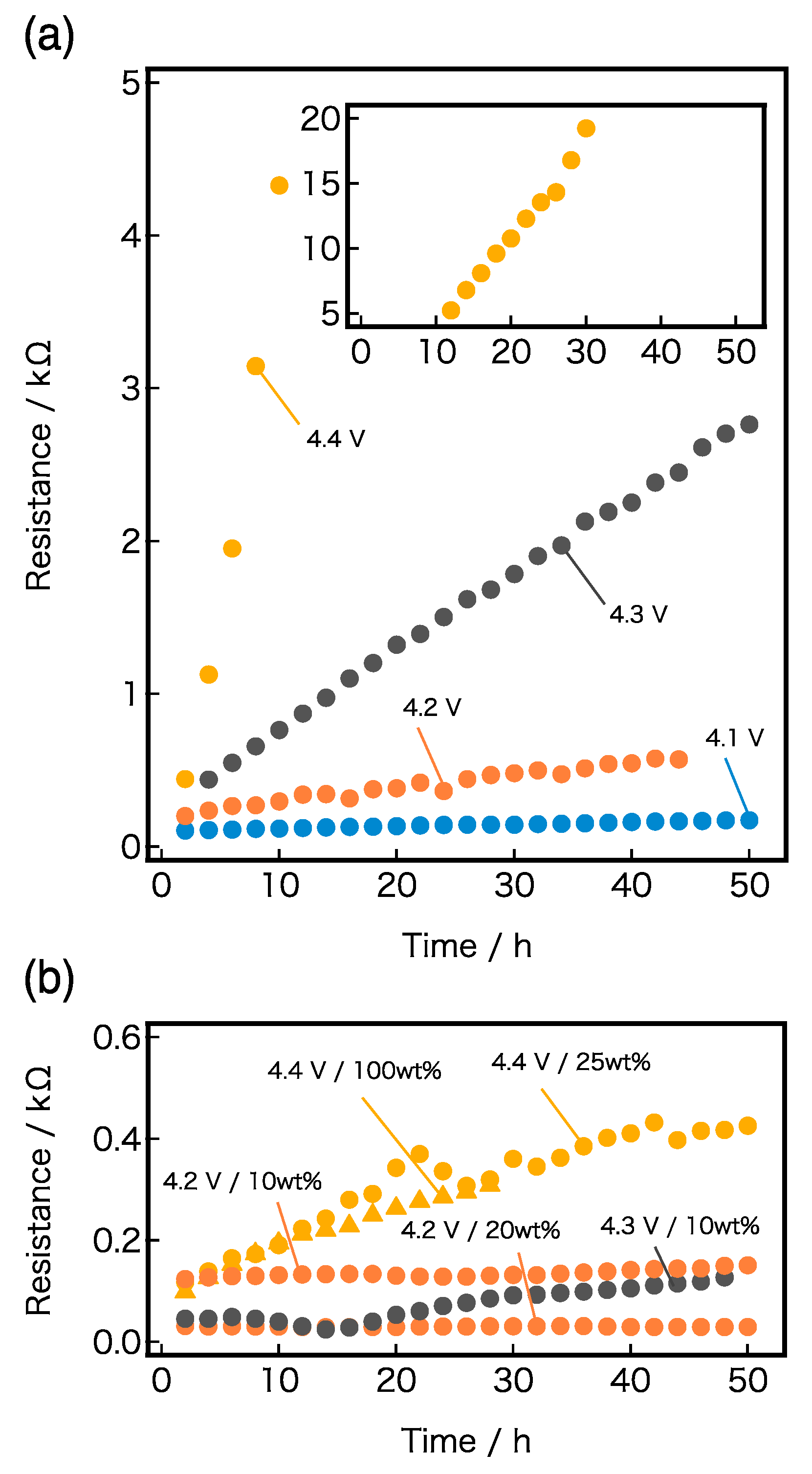
The variations in
RLiCoO2 with time for various applied potentials are shown in
Figure 4a,b. A large difference was observed in the rate of increase between the systems with and without LiPF
6. As shown in
Figure 4a, the PEO-LiTFSI/LiCoO
2 interface resistance
RLiCoO2 increased slightly with time, even under the applied voltage of 4.1 V vs. Li/Li
+, and under higher voltages, the slope increased significantly with time and R
LiCoO2 rose exponentially with the applied voltages. The result from the interfacial resistance measurement is consistent with previous reports on the decomposition potential of PEO-related electrolytes, which fell in the range of 3.7–4.1 V [
8,
9]. In contrast, the interface of PEO-LiTFSI-LiPF
6/LiCoO
2 was largely stabilized by the presence of LiPF
6, as shown in
Figure 4b, where the change in resistance with time for the SPEs with LiPF
6 is plotted under applied potentials of 4.2 to 4.4 V vs. Li/Li
+. At 4.2 V and 4.3 V vs. Li/Li
+, R
LiCoO2 showed almost no variation with time; even at 4.4 V vs. Li/Li
+, only a slight increase in resistance from 100 Ω to 400 Ω was observed during the exposed time of 50 h, which significantly contrasted with the large increase in resistance from 400 Ω to 20,000 Ω during the 30 h period with the non-doped PEO-LiTFSI system. Therefore, LiPF
6 plays an important role in stabilizing the polymer electrolyte/LiCoO
2 interface, even at only 10 wt% addition.
Figure 5 shows charge–discharge curves and the cycle performance between 2.5 V and 4.4 V for Li/PEO-LiTFSI-LiPF
6/LiCoO
2 cells with 0 wt%, 25 wt%, and 100 wt% of added LiPF
6. A significant difference in cell performance was observed with and without LiPF
6. The cells with SPE containing LiPF
6 display stable charge/discharge curves and cycling performance with a capacity retention of 150 mAh/g after 20 cycles. The capacity during charge for the cell without LiPF
6 dropped to 100 mAh/g from the first discharge capacity of 170 mAh/g after 20 cycles. In the cut-off voltage of 2.5–4.5 V, degradation of the cycle performance was also appreciably suppressed in the case of LiPF
6 addition (
Figure 6). The cell with the SPE containing 10 wt% LiPF
6 maintained a capacity of 100 mAh/g after 100 cycles, the retention of which is 53%, as calculated from the capacity of 190 mAh/g in the first discharge.
The electrochemical stability window of SPE should be the same as that of the electrode potential or higher. For 4 V class cathodes with operating voltages as high as 4.2–4.4 V vs. Li/Li
+, stability at 4.5 V vs. Li/Li
+ is, at least, required to compensate for the overpotential during charge [
31]. The PEO-based SPE including LiPF
6 as a Li salt has the possibility to meet these criteria, although further electrochemical investigation will be necessary. At the moment, it is unclear as to what the stability enhancement of the polymer/cathode interface can be attributed to by the addition of LiPF
6 as a lithium salt to the PEO electrolyte. Detailed surface analyses are also desirable as a next step.


 ,
, 


