Article

Hydrocyclone Separation of Hydrogen Decrepitated NdFeB †

1
School of Chemical Engineering, University of Birmingham, Edgbaston, Birmingham B15 2TT, UK
2
School of Metallurgy and Materials, University of Birmingham, Edgbaston, Birmingham B15 2TT, UK
*
Author to whom correspondence should be addressed.
This paper is an extended version of our paper published in 6th International Conference Quo Vadis. Recycling, High Tatras, Slovak Republic, 6–9 June 2017.
Recycling 2017, 2(4), 22; https://doi.org/10.3390/recycling2040022
Submission received: 23 August 2017 / Revised: 31 October 2017 / Accepted: 13 November 2017 / Published: 14 November 2017
(This article belongs to the Special Issue Quo Vadis Recycling 6)

Abstract

:
Hydrogen decrepitation (HD) is an effective and environmentally friendly technique for recycling of neodymium-iron-boron (NdFeB) magnets. During the HD process, the NdFeB breaks down into a matrix phase (Nd2Fe14BHx) and RE-rich grain boundary phase. The grain boundary phase in the HD powder is <2 μm in size. Recycled NdFeB material has a higher oxygen content compared to the primary source material. This additional oxygen mainly occurs at the Rare Earth (RE) rich grain boundary phase (GBP), because rare earth elements oxidise rapidly when exposed to air. This higher oxygen level in the material results in a drop in density, coercivity, and remanence of sintered NdFeB magnets. The particle size of the GBP is too small to separate by sieving or conventional screening technology. In this work, an attempt has been made to separate the GBP from the matrix phase using a hydrocyclone, and to optimise the separation process. HD powder, obtained from hard disk drive (HDD) scrap NdFeB sintered magnets, was used as a starting material and passed through a hydrocyclone a total number of six times. The X-ray fluorescence (XRF) analysis and sieve analysis of overflows showed the matrix phase had been directed to the underflow while the GBP was directed to the overflow. The optimum separation was achieved with three passes. Underflow and overflow samples were further analysed using an optical microscope and MagScan and matrix phase particles were found to be magnetic.

1. Introduction

The growing need for sustainable technologies is resulting in an increasing emphasis on the recycling of materials. This development is particularly important in the case of rare earth elements (REEs). These rare earth-based magnets—especially Neodymium-iron-boron (NdFeB) magnets—possess the highest energy product of all permanent magnets, which makes them highly efficient and suitable for lightweight mobile applications [1]. Therefore, they are widely used in computer hard drives (HDDs), loudspeakers, medical imaging, household electrical appliances, hybrid and electric vehicles (HEVs and EVs), wind turbines, and many other small consumer electronic devices. About 48% of total NdFeB magnets produced in 2012 were used in the production of motors, generators, HDD, CDs and DVDs. The amount being used varies between a few grams (e.g., loudspeakers) to tonnes of materials (e.g., wind turbines) [2].
In recent years, the increasing popularity of hybrid and electric cars and wind turbines has caused an increase in the demand for rare earth. China is currently producing more than 95% of these rare earth elements [3]. Growing demand for REEs and restrictions on the supply from the China have already triggered a rare earth crisis in the past. The reason being that the supply of these rare earths is dependent on single source, i.e., China, and this supply risk can be felt outside China. In the report on critical raw materials for the EU published in 2014, the European Commission considers rare earth elements as the most critical raw materials group, with the highest supply risk [4]. Moreover, it is anticipated that the demand for neodymium and dysprosium for production of magnets could rise by 700% and 2600%, respectively, over the next 25 years [5].
Previous studies have shown that hydrogen can efficiently be used to separate NdFeB magnets from HDD scrap [6,7]. NdFeB magnets become demagnetised when reacted with hydrogen, thus allowing the powder to be separated much more readily. During this hydrogen decrepitation process, the NdFeB magnets absorb hydrogen and break down into an interstitial matrix phase hydride (Nd2Fe14BHx) and a grain boundary phase hydride. The average particles size of grain boundary phase is <2 μm [8], whereas the matrix phase breaks down in particle sizes ranging from 10 to 500 μm, depending on hydrogen cycling [9]. It should be noted that the HD powder is very friable due to the presence of microcracks in the particles [10]. Therefore, this HD powder can easily be milled down (using a jet mill) to the particle size required for sintering.
During sintering of NdFeB magnets, the RE-rich GBP melts down, resulting in liquid phase sintering. When the recycled HD powder is used to re-manufacture sintered NdFeB magnets, the GBP has a higher oxygen content and therefore it does not fully melt during the re-sintering process, which results in a lower-density magnet and reduction in magnetic properties. This liquid phase sintering process in recycled magnets can be improved by adding fresh neodymium hydride to the recycled material [8,11,12]. The aim of this work is, therefore, to separate the grain boundary phase (<2 μm) with higher oxygen content from the matrix phase using a hydrocyclone, and optimise the process to achieve optimum separation.
Hydrocyclones have been used in the chemical and mineral industries for many years. Their usage is very wide in the mineral, chemical and bio-industries due to the simple design, operational flexibility and low operation and maintenance costs. The devices use centrifugal forces to separate two products of different densities or sizes [13,14]. Despite their simplicity and low cost, they are very efficient for solid-liquid separations [15].

2. Experimental

2.1. Material

The starting material used in this study was a hydrogen decrepitated (HD) powder obtained from hard disk drive (HDD) scrap. A batch of NdFeB magnets, obtained from hard disk drive scrap, was processed at 2 bar hydrogen and room temperature for 2–4 h. The extraction of NdFeB magnets from hard disk drives and processing is explained in detail by Walton et al., 2015 [6]. Hydrogen decrepitated material was then exposed to air (for controlled oxidation) before mixing it with water. In this case, water acts as a medium for processing of the powder through the cyclone and it reduces the build-up of triboelectric charges between fine particles [16]. This, therefore, allows for better separation efficiency in the case of very fine particles.

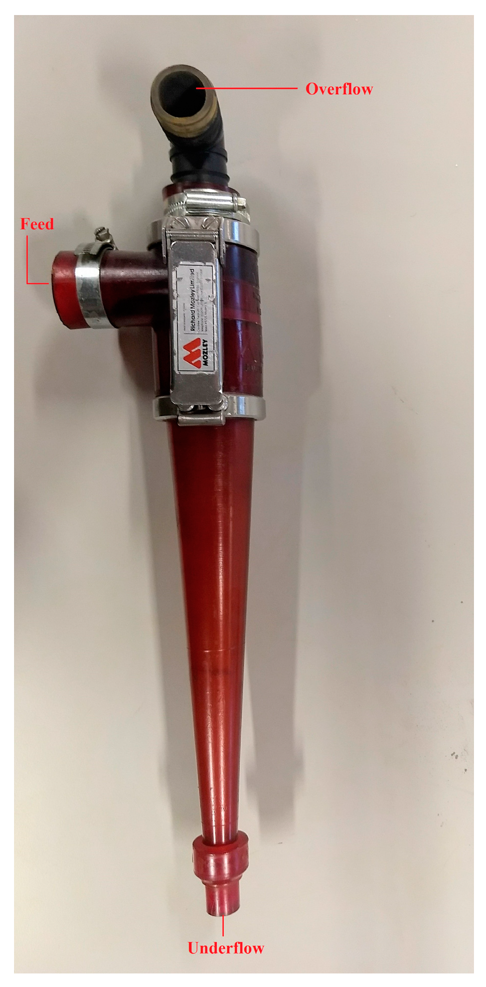
2.2. Working Principle of Hydrocyclones
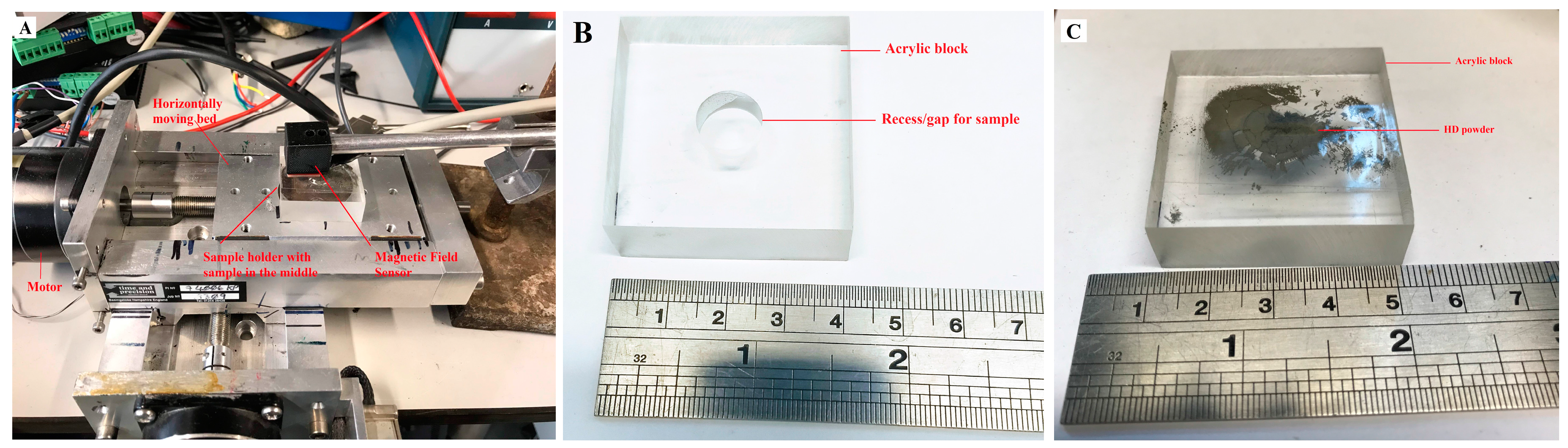
A hydrocyclone consists of two main parts, as shown in Figure 1. The first is a cylindrical part with feed inlet. This part also includes an outlet, located at the top of the cylinder, extends into the cylinder and is known as the vortex finder. The second main part is conical, and is connected to the cylindrical section at the top and to the underflow at the bottom end. The latter part is known as the spigot [17].
The feed slurry, under pressure, enters at the tangential inlet at the top of the hydrocyclone. As the feed enters the chamber, a rotation of the slurry inside of the hydrocyclone begins to accelerate the movement of the particles. This circular acceleration of the fluid directs the heavier particles towards the outer wall under the action of a centrifugal force. The particles migrate in a spiral pattern through the cylindrical section into the conical section. Depending on the particle size, the radial movement is hindered by the drag force as the particles move through the carrying fluid. At this point, the smaller particles migrate toward the centre of the hydrocyclone and spiral upward through the vortex finder. This product, which contains the finer particles and the majority of the water, is termed the overflow. As the flow descends in the hydrocyclone, the layer adjacent to the hydrocyclone wall becomes loaded with heavy particles, which exit the device through the spigot orifice of the cyclone, is termed as underflow [13,14].

2.3. Methods

The experiments were carried out with a Mozley C700 rig, using a 50 mm hydrocyclone (vortex finder size was 14.3 mm and diameter of the spigot was 4.5 mm). The system was operated at a constant feed pressure of 0.8 bar. 1 kg of HD material was mixed with 10 litres of water in the tank, and circulated through the cyclone. At equilibrium, the hydrocyclone underflow and overflow were sampled for a set period, normally 2 s. Underflow and overflow sample volumes were measured. The underflow of the previous pass was mixed with 10 L water and used as the feed for the next pass. The experiment was repeated for six passes, and samples were collected after each pass.
Samples collected from each pass were then filtered and dried at 80 °C in an oven in air. These samples were then analysed using an XRF spectrometer (S8 Tiger, Haworth 503A) with ±0.50 weight % precision in measurement. The loose powder method was chosen to analyse these samples, as described in detail by Gakuto [18]. Full detection mode was selected for XRF. Oxygen analysis was performed by Less Common Metals (LCM), Cheshire, UK using a LECO instrument. 40 g of each underflow and 10 g of overflow were sieved using Retsch Vibratory Sieve Shaker AS 200. The amount on each sieve was recorded using and HR120 laboratory balance with a precision value of ±0.0002 g.
Particle size distribution of the starting material and first pass was performed using a Malvern Mastersizer 2000S and by Sympatec Qicpic 119D. The magnetic field mapping system (MagScan), supplied by Redcliffe Magtronics, was used to determine the location and magnetic strength of HD powder. The magnetic field exhibited by the sample was measured by three orthogonal hall probes situated within a probe head, allowing a resolution of 0.1 × 0.1 mm. The probe head was set to scan 40 × 40 mm, which was controlled by the computer. The MagScan produced an image showing contrasting colours, depending on the strength and direction of the field detected by the hall probes. The sensitivity of the MagScan used was 0.027 mT. A more sensitive custom-made Line Scan was also used in this work, which produced a line depending on the strength of the field above the powder. This line scan used a Mag3110 magnetometer from Freescale with a resolution of 100 nT, calibrated against a Lakeshore DSP 455 Gaussmeter and the setup is shown in Figure 2A. HD powder was filled in the acrylic block as shown in the figure as shown in Figure 2B. The recess in the acrylic block was 10 mm in diameter and 5 mm deep. The block was then placed on a horizontally moving bed controlled by the motor and moved under the magnetic field sensor. Image J software and Joel 6060 scanning electron microscope (SEM) was used to determine the particle sizes and a theoretical maximum of RE-Rich in the starting material.

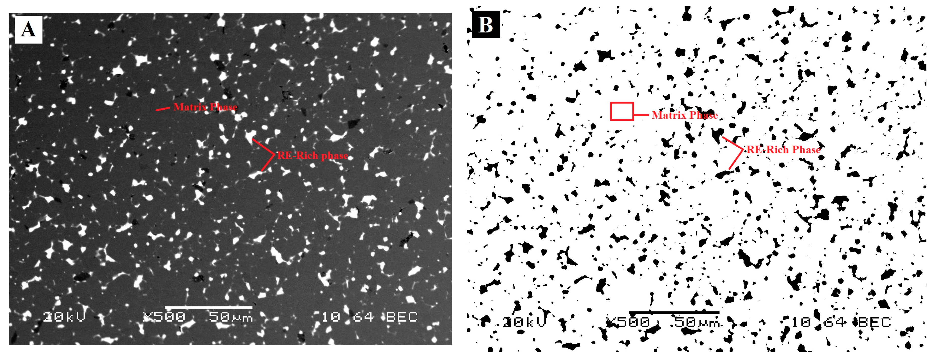
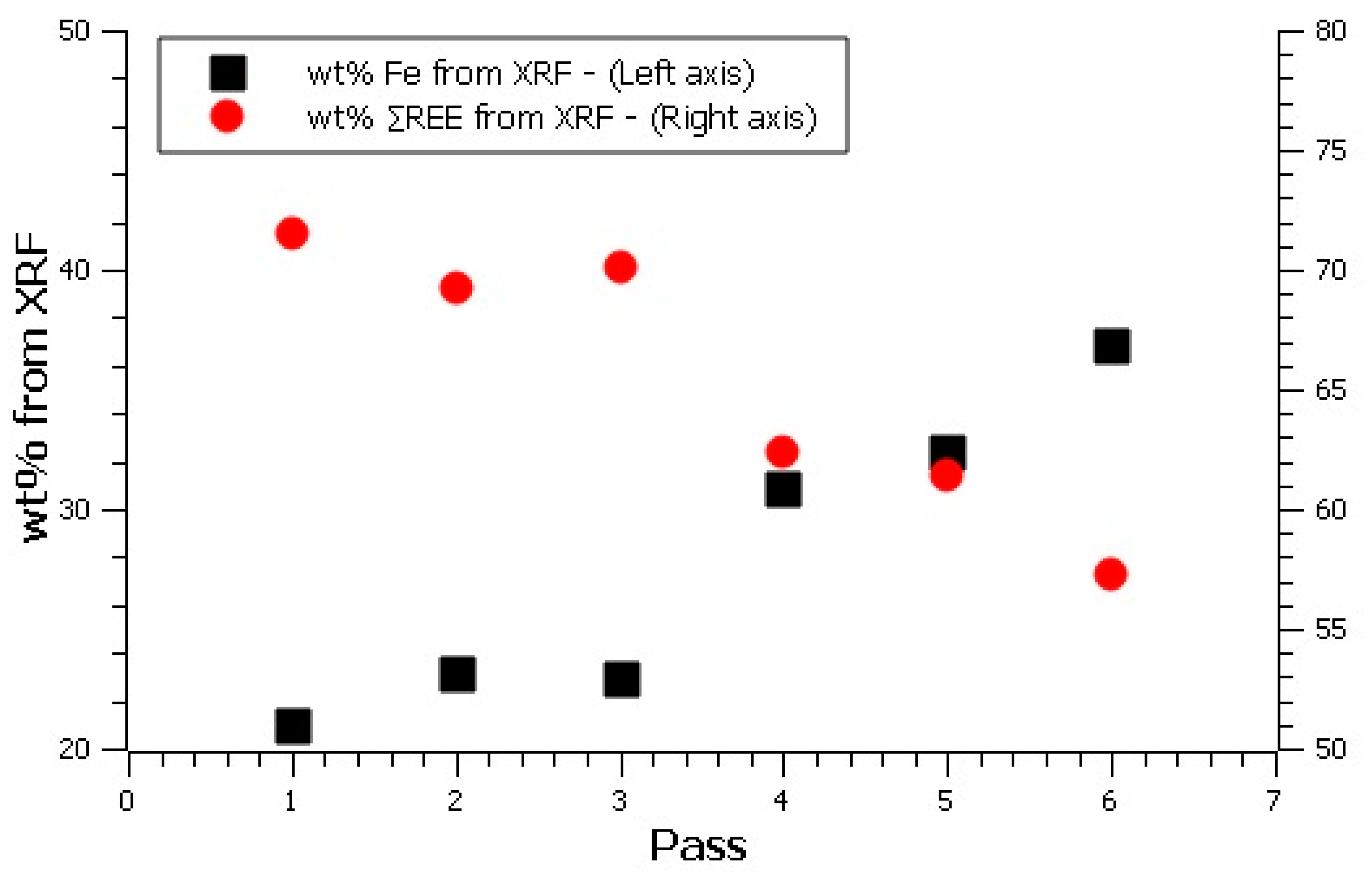
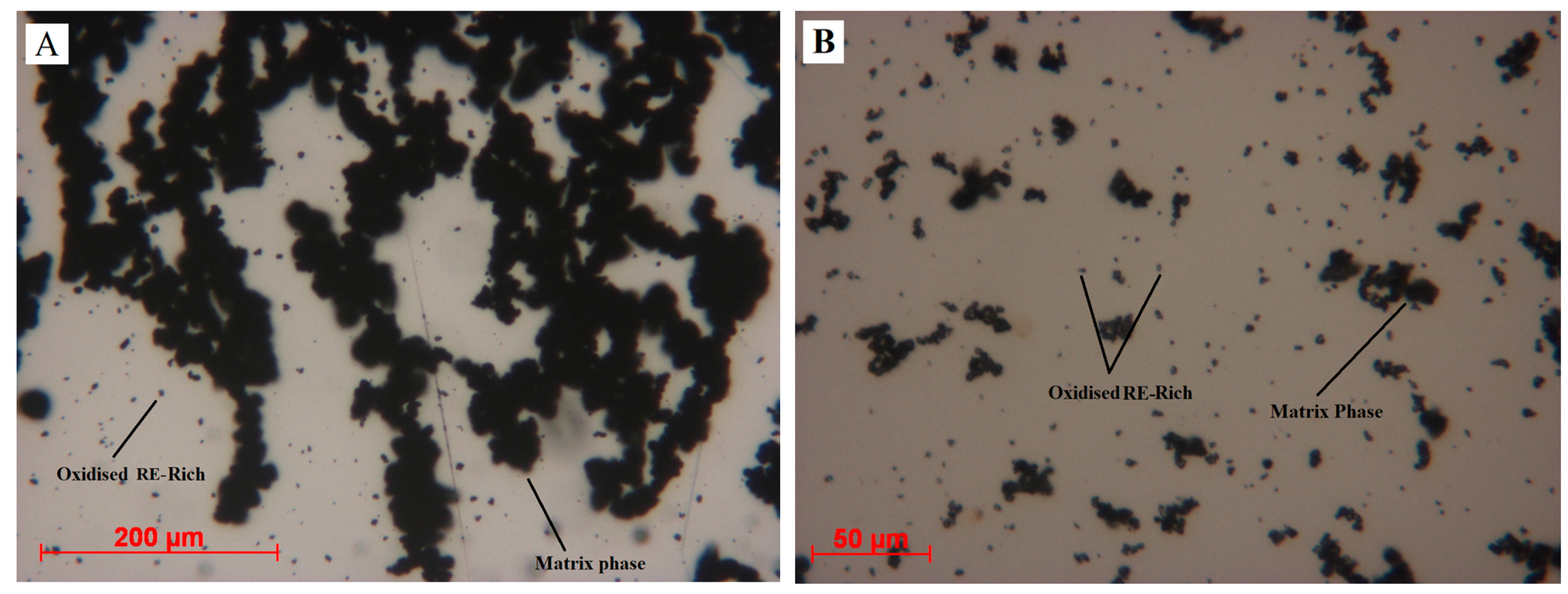
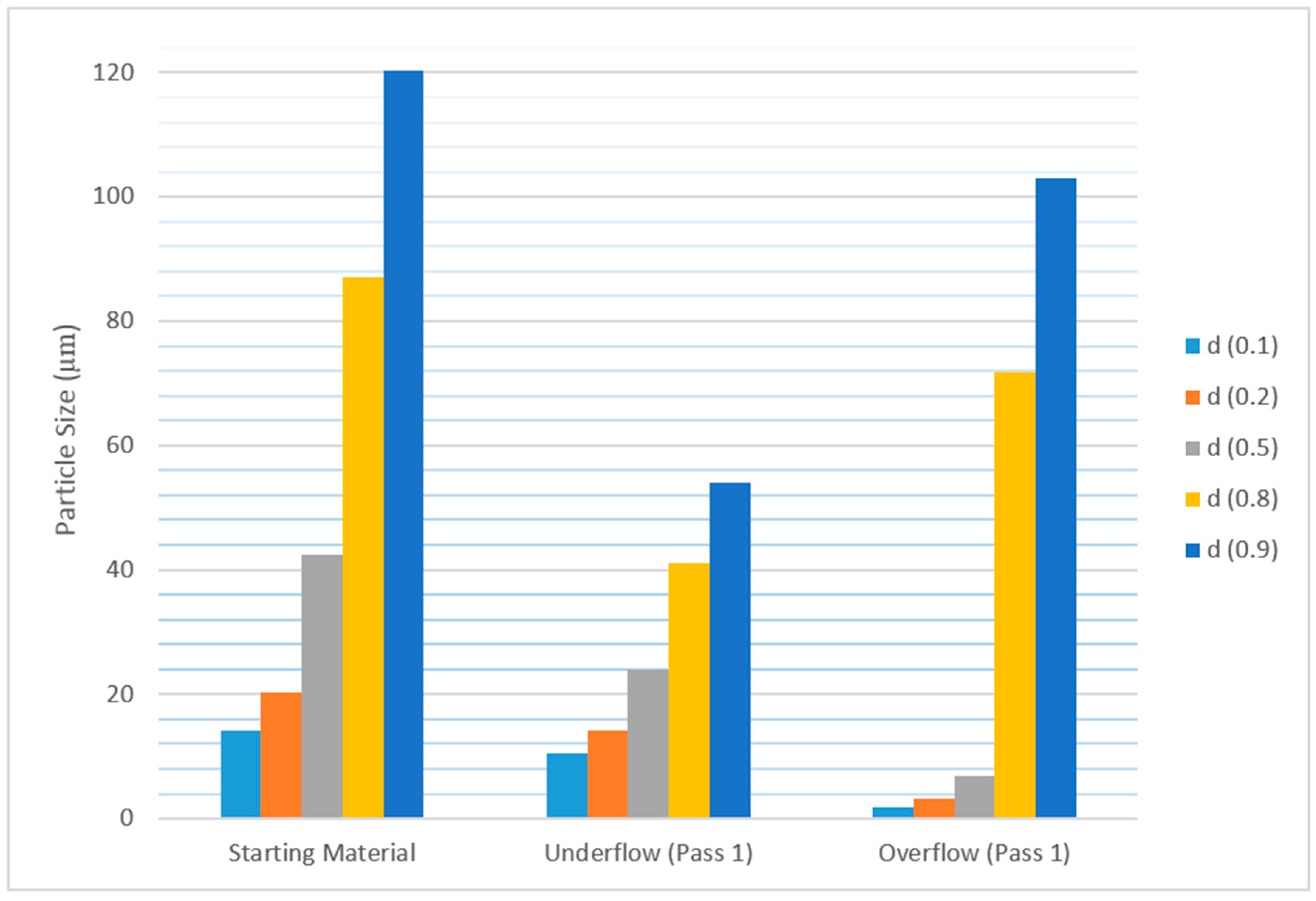
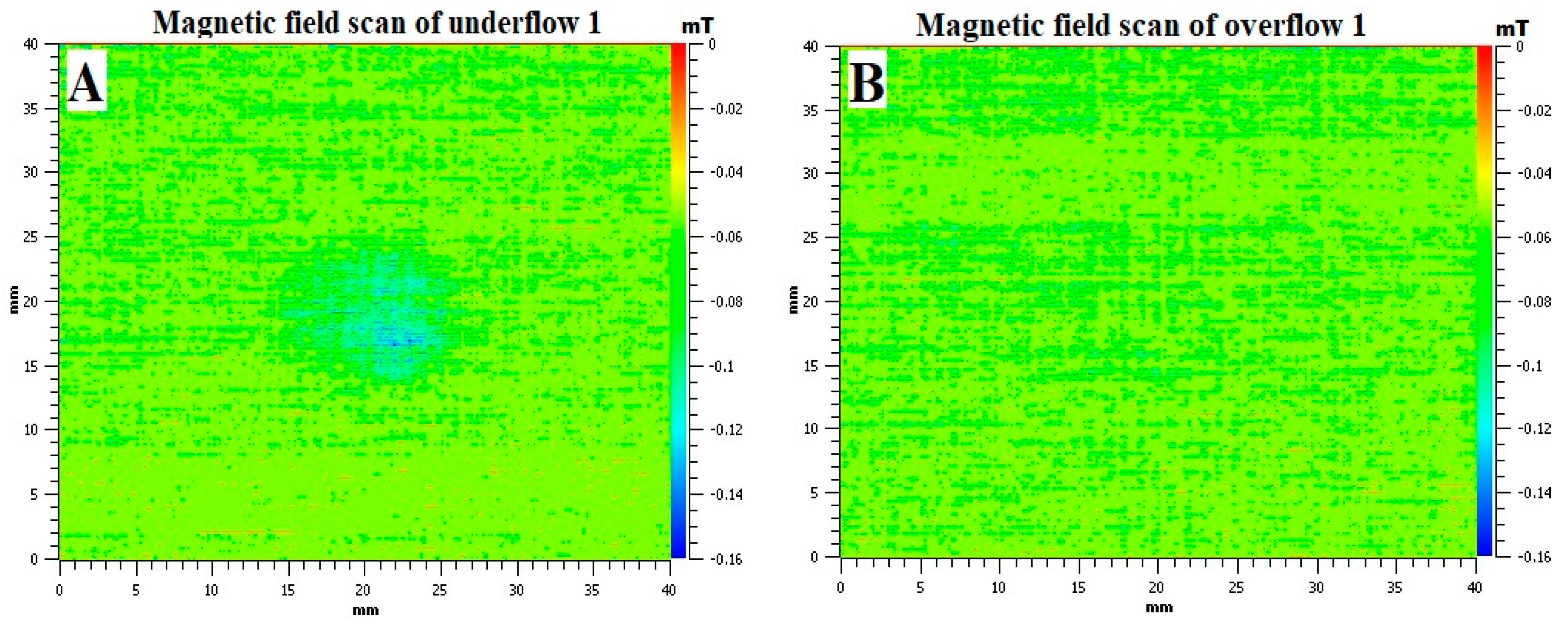
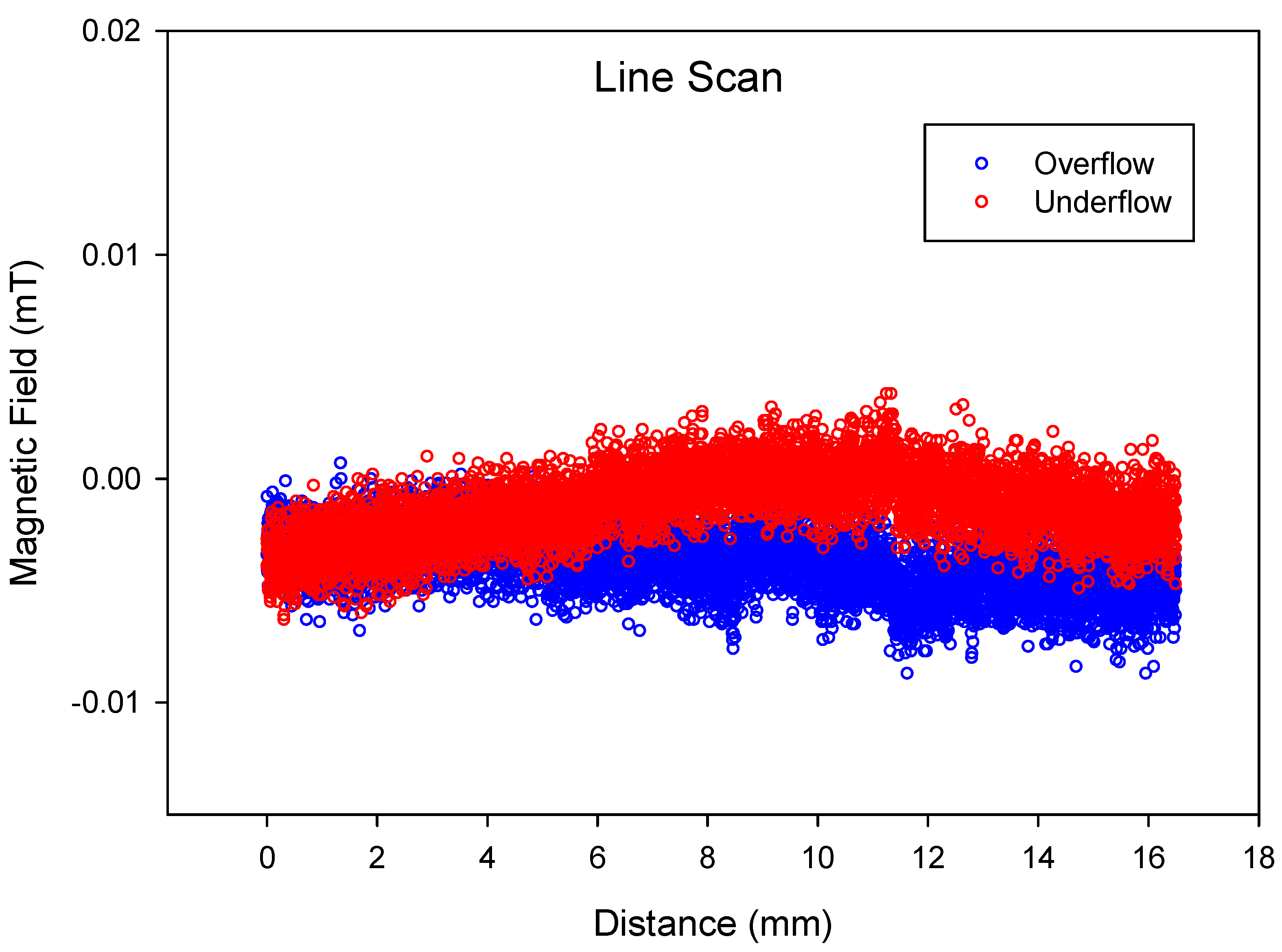
3. Results and Discussion

A VCM magnet was mounted in conductive bakelite, and the microstructures were analysed using SEM. The theoretical maximum amount of RE-rich (as shown in Figure 3A,B) present in the magnets was estimated by computing the total area of RE-rich in an SEM image. Image J was used for this estimation and the area fraction was then converted into mass by multiplying with density. It should be noted that the theoretical maximum of RE-rich phase was an estimation, and it was assumed that the intergranular RE-rich phase was uniformly distributed, and that the volume of RE-rich phase was the same as the area fraction. To minimise the error, and taking into account the uneven distribution of RE-rich phase, 10 different SEM images were taken at different locations. After setting the threshold in Image J, these images were then converted into a binary images, and the area fraction was calculated. The maximum and minimum value of area fraction was 9.7% and 6.6%, respectively, with a standard deviation of 1.14. The SEM and binary images used are presented in Figure 3. The average of these areas was then used for calculation. The theoretical maximum was estimated to be 8% by weight. Thus, in 1 kg of starting material, it was expected that there would be a maximum of 80 g of RE-rich phase.
Results from hydrocyclone separation are presented in Table 1 below. There was a very small number of particles separated as overflow in the first three hydrocyclone passes, although this increased in last three passes due to the action of the pump.
Underflows and overflows collected from all of these passes (after drying) were then sieved again through different mesh sizes to classify the collected material based on particle sizes. Table 2 gives the percentage of underflow samples collected at each sieve. It should be noted that a sample size of 40 g was used for sieving, as it is representative of the material collected as underflow during each pass.
It is clear from Table 2 that about 20% (by weight) of the HD material used in this study was comprised of particles larger than 125 µm, and more than half of the material had particles less than 38 µm in size. As the material was passed through the hydrocyclone, the particle size distribution was changed. The HD material, being very friable, broke down inside the rotary pump and hydrocyclone, continuously generating smaller particles. These particles were then directed to the overflow with the very fine particles.
Sieving data of samples collected as overflow is presented in Table 3, below. In this case, a sample size of 10 g was used for all overflows. It can be seen that, for the first two passes, the majority of the particles were less than 45 µm, and no material with a particle size larger than 63 µm was collected. As we move on to the third pass, larger particles started to appear on higher mesh size sieves. It can be noted that particle less than 38 µm in size were removed by the hydrocyclone as overflow up to the third pass. No considerable amount of particles less than 38 µm was collected after the third pass.
Table 4 presents the results obtained from XRF and oxygen analysis of the feed and underflow fractions. The term ∑REE represents the sum of rare earth elements in the material (Nd + Dy). The hydrided matrix phase (Nd2Fe14BHx), being large-sized particles, should report to the underflow; and grain boundary phase, being smaller, should report to the overflow. As both of these particles have Nd in them, the number of passes required for optimum separation is based on total rare earth elements and concentration of iron. It should be noted that XRF data is normalised to 100% and the amount of oxygen was determined using different equipment at a later stage.
It can be seen from the Table 4 that the concentration of iron increased with each hydrocyclone pass, whereas the amount of neodymium (Nd) decreased as expected. The slight variation in the values of Nd and Dy could be associated with the precision of the equipment.
The XRF and oxygen analysis of the overflow fractions are presented in Table 5. The overflows were found to be rich in Neodymium. The presence of Fe in the overflow indicates that some of the large particles (matrix phase) were present in overflow alongside small particles (GBP). Moreover, Dy was also present in the GBP, which means that the Dy and Nd detected in the overflow originated in both the matrix phase and the GBP. From the fourth pass, the amount of Fe suddenly started to increase in the overflow, meaning that, after the third pass, there was more matrix phase in the overflow than the grain boundary phase. Sieving data of overflows (Table 3) also agrees with this hypothesis. After the third pass, the continuous production of smaller particles affected the separation process, and no particles smaller than 38 µm were collected on the sieves, or the remaining small particles adhered to the larger particles by triboelectric charges, and could not be further separated [16].
The plot of ∑REE and Fe (Figure 4) from XRF shows that the REE-rich decreased and the Fe content increased after the 3rd pass. From this, we can assume that the overflows of first three passes were mainly RE-rich particles, and so can assume a separation efficiency close to 45% after three passes.
The oxygen content in all underflow samples (Table 4) was slightly higher than the starting material (feed), which is likely to be due to the neodymium reacting with water to form neodymium hydroxide [8,19]. Formation of Nd(OH)3 increases the amount of oxygen present in the starting material. On the other hand, there was a considerably higher amount of oxygen present in overflow streams (Table 5). This means that the smaller particles, which were mainly neodymium oxide and hydroxide, were successfully separated from the matrix phase by this separation process.
The particle size distribution results from the Mastersizer are shown in Figure 5, below. The figure shows that the particles in the starting material (feed) were distributed between 1.5 µm and 120 µm, and 10% of total particles were smaller than 14 µm.
It can be seen from the above figure that the particle size in the underflow obtained after the first pass had reduced considerably. This confirms that the larger particles present in the feed keep breaking down into smaller particles as they pass through the hydrocyclone system.
The overflow stream contains mainly smaller particles (GBP), along with some larger particles (matrix phase). Evidence of the presence of matrix phase in overflow was also found in the chemical analysis (Table 5) and sieving data (Table 3). Figure 5 also shows that particle size distribution (D50) had reduced from 42 µm (starting material) to 24 µm in underflow just after the first pass.
The measurement of particle size distribution was then repeated using Sympatec Qicpic 119D, and it was noticed that the none of the samples were free-flowing material. Figure 6 shows the images of some of the particles larger than 100 µm in underflow 1 taken by the Qicpic camera. From these images, it can be seen that larger particles are random in shape, and a clear void can also be noticed in some of the particles. These images suggest that these are not individual particles, but more than one particle clumped together. Thus, accurate measurement of particle size distribution in any of the samples is not possible using the optical or laser-based equipment. For all these techniques, for particle analysis to work properly, the particles must be deagglomerated.
To investigate this agglomeration, underflow 1 and overflow 1 were mixed with water and observed under the Leitz optical microscope. To start with, a clear visual difference between underflow and overflow was noticed. The overflow was light coloured and the underflow was grey. Two drops of each suspension were dropped onto a mirror and spread evenly using a glass slide. The images of underflow and overflow are presented as Figure 7A,B respectively.
Matrix phase and RE-rich particles are highlighted in Figure 7. Matrix phase particles are agglomerated forming a chain network. On the other hand, oxidised RE-rich particles can be seen individually on the surface of the mirror. When a magnet was brought close to these particles, the matrix phase responded to the movement of the magnet, whereas no movement was observed in oxidised RE-rich particles. Based on this information, it was suspected that the HD particles were not fully demagnetized. Rather, they attract each other with very weak magnetic force to form agglomerations.
Figure 7A shows the powder forming chain-like structures; from this, we suspected that the particles from the matrix phase still had remanent magnetization and were interacting with each other, forming chain-like agglomerations. To confirm this observation, these samples were analysed for their magnetic field using MagScan.
The contrasting colour images produced by MagScan for underflow 1 and overflow 1 are shown in Figure 8. It can be seen that the underflow has a slight magnetic field in the area where the sample was placed, as shown in Figure 2B. On the other hand, the overflow does not show any magnetic field. This confirms the observation made in Figure 6 that the matrix phase particles are still magnetic, even after exposure to water.
This was also confirmed by a more sensitive in-house-built MagScan (Figure 2A), and the Line Scan of underflow and overflow is presented in Figure 9. It can be concluded from the figure that both samples are slightly magnetic, but that the underflow has more magnetic field than the overflow. The reason for this difference in the magnetic field is the amount of matrix phase and oxidised RE-rich present in each sample. The overflow contains mostly oxidised RE-rich, with some matrix phase, as confirmed by Figure 7B.

4. Conclusions

Hydrocyclone separation has been shown to be an effective method for separating the matrix Nd2Fe14BHx from the oxygen-rich grain boundary phase for HD processed NdFeB. The oxygen-rich grain boundary phase was successfully separated in the overflow along with some matrix phase particles. The chemical analysis indicated that one-third of the overflow consisted of the matrix phase. The underflows were then able to be processed into sintered NdFeB magnets with the addition of fresh neodymium hydride. This hydrocyclone separation process was also optimised, and the total number of passes required for optimum separation was found to be three. The very fine particles were removed up to the third pass. After the third pass, more matrix phase was found in the overflow, resulting in a yield loss. The HD powder was found to be slightly magnetic and friable, which limits the separation process and the use of conventional techniques used to determine particle size distribution. The difference in the magnetic field of underflow and overflow and neodymium oxide being non-magnetic open up the potential for further separation techniques, which will be published shortly.

Acknowledgments

The research leading to these results has received funding from the European Community’s Horizon 2020 Programme (H2020/2014–2019) under Grant Agreement no. 674973 (MSCA-ETN DEMETER). This publication reflects only the authors’ view, exempting the Community from any liability. Project website: http://etn-demeter.eu/. Enrique Herraiz received funding from the European Community’s Seventh Framework Programme ([FP7/2007–2013]) under grant agreement no. 607411 (MC-ITN EREAN: European Rare Earth Magnet Recycling Network). Project website: http://www.erean.eu. The authors would also like to thank Less common metals (LCM), UK for oxygen analysis.

Author Contributions

Malik Degri and Enrique Herraiz designed the experiments. Muhammad Awais, Fernando Coelho, Malik Degri performed the experiments and analysed the data. Muhammad Awais wrote the paper and is the corresponding author. Allan Walton and Neil Rowson contributed to the design of experiments and and made a significant contribution to writing.

Conflicts of Interest

The authors declare no conflict of interest.

References

  1. Jiles, D. Introduction to Magnetism and Magnetic Materials; CRC Press: Boca Raton, FL, USA, 2015; ISBN 9781482238877. [Google Scholar]
  2. Yang, Y.; Walton, A.; Sheridan, R.; Güth, K.; Gauß, R.; Gutfleisch, O.; Buchert, M.; Steenari, B.; van Gerven, T.; Jones, P.T.; et al. REE Recovery from End-of-Life NdFeB Permanent Magnet Scrap: A Critical Review. J. Sustain. Metall. 2017, 3, 122–149. [Google Scholar] [CrossRef]
  3. European Commission. List of Critical Raw Materials for the EU; European Commission: Brussels, Belgium, 2017. [Google Scholar]
  4. European Commission. Report on Critical Raw Materials for the EU; European Commission: Brussels, Belgium, 2014. [Google Scholar]
  5. Alonso, E.; Sherman, A.M.; Wallington, T.J.; Everson, M.P.; Field, F.R.; Roth, R.; Kirchain, R.E. Evaluating Rare Earth Element Availability: A Case with Revolutionary Demand from Clean Technologies. Environ. Sci. Technol. 2012, 46, 3406–3414. [Google Scholar] [CrossRef] [PubMed]
  6. Walton, A.; Yi, H.; Rowson, N.A.; Speight, J.D.; Mann, V.S.J.; Sheridan, R.S.; Bradshaw, A.; Harris, I.R.; Williams, A.J. The use of hydrogen to separate and recycle neodymium-iron-boron-type magnets from electronic waste. J. Clean. Prod. 2015, 104, 236–241. [Google Scholar] [CrossRef]
  7. Gutfleisch, O.; Güth, K.; Woodcock, T.G.; Schultz, L. Recycling Used Nd-Fe-B Sintered Magnets via a Hydrogen-Based Route to Produce Anisotropic, Resin Bonded Magnets. Adv. Energy Mater. 2013, 3, 151–155. [Google Scholar] [CrossRef]
  8. Herraiz, E.D.M.; Bradshaw, A.; Sheridan, R.S.; Mann, V.S.J.; Harris, I.R.; Walton, A. Recycling of rare earth magnets by hydrocyclone separation and re-sintering. In Proceedings of the 24th International Workshop on Rare Earth Permanent Magnet and Their Applications, Darmstadt, Germany, 28 August–1 September 2016. [Google Scholar]
  9. Scholz, U.D.; Kronert, W.E.; Nagel, H. A contribution to the mechanism of the hydrogenation of NdFeB alloys and the use of hydrogenated alloy for permanent magnet production. In Proceedings of the 9th International Workshop on Rare-earth Magnets and their Applications, Bad-Soden, Germany, 31 August–3 September 1987. [Google Scholar]
  10. Harris, I.R.; McGuiness, P.J. Hydrogen: Its use in the processing of NdFeB-type magnets. J. Less-Common Metals 1991, 174, 1273–1284. [Google Scholar] [CrossRef]
  11. Zakotnik, M.; Harris, I.R.; Williams, A.J. Multiple recycling of NdFeB-type sintered magnets. J. Alloys Compd. 2009, 469, 314–321. [Google Scholar] [CrossRef]
  12. Rivoirard, S.; Noudem, J.G.; de Rango, P.; Fruchart, D.; Liesert, S.; Sobeyroux, J.L. Proceedings of the 16th International Workshop on Rare Earth Magnets and Their Applications, Sendai, Japan, 10–14 September 2000; Japan Institute of Metals: Sendai, Japan, 2000; p. 355. [Google Scholar]
  13. Freeman, R.J.; Rowson, N.A.; Veasey, T.J.; Harris, I.R. The development of a magnetic hydrocyclone for processing finely ground magnetite. IEEE Trans. Magn. 1994, 30, 4665–4667. [Google Scholar] [CrossRef]
  14. Wills, B.A. Mineral Processing Technology, 5th ed.; Pergamon Press: Oxford, UK, 1992; ISBN 978-0080418858. [Google Scholar]
  15. Svarovsky, L. Solid-Liquid Separation; Butterworth Heinemann: Oxford, UK, 2000; pp. 191–243. ISBN 0750645687. [Google Scholar]
  16. Dobbins, M.; Dunn, P.; Sherrell, I. Recent advances in magnetic separator designs and applications. In Proceedings of the 7th International Heavy Minerals Conference: What Next, Drakensberg, South Africa, 20–23 September 2009. [Google Scholar]
  17. Habibian, M.; Pazoukib, M.; Ghanaiea, H.; Abbaspour-Sanib, K. Application of hydrocyclone for removal of yeasts from alcohol fermentations broth. Chem. Eng. J. 2008, 138, 30–34. [Google Scholar] [CrossRef]
  18. Takahashi, G. Sample preparation for X-ray fluorescence analysis III. Pressed Loose Powder Methods. Rigaku J. 2015, 31, 29. [Google Scholar]
  19. Fredericci, C.; de Campos, M.F.; Braga, A.P.V.; Nazarre, D.J.; Martin, R.V.; Landgraf, F.J.G.; Périgo, E.A. Nd-enriched particles prepared from NdFeB magnets: A potential separation route. J. Alloys Compd. 2014, 615, 410–414. [Google Scholar] [CrossRef]
Figure 1. A typical hydrocyclone (Image taken by Malik Degri).
Recycling 02 00022 g001
Figure 2. (A) In-house built MagScan with higher sensitivity; (B) acrylic block/sample holder without sample; (C) Prepared sample.
Recycling 02 00022 g002
Figure 3. (A) Backscattered SEM image; (B) Binary image of SEM produced by Image J.
Recycling 02 00022 g003
Figure 4. Change in REE and Fe concentraion in the overflows with number of passes.
Recycling 02 00022 g004
Figure 5. Particle size distribution in feed, underflow and overflow after first pass.
Recycling 02 00022 g005
Figure 6. Images of particles larger than 100 µm taken by built-in camera in Qicpic.
Recycling 02 00022 g006
Figure 7. Underflow (A) and overflow (B) mixed with water and images taken by optical microscope.
Recycling 02 00022 g007
Figure 8. MagScan images of underflow (A) and overflow (B) after first hydrocyclone pass.
Recycling 02 00022 g008
Figure 9. Line Scan of underflow and overflow after first hydrocyclone pass.
Recycling 02 00022 g009
Table 1. Hydrocyclone data for hydrogen decrepitated NdFeB.
Hydrocyclone PassesFeed (g)Underflow (g)Overflow (g)Overflow/Reject (%)Underflow/Yield (%)
Pass 11000.00987.0712.931.2998.71
Pass 2793.67779.9313.741.7398.27
Pass 3653.32642.7610.571.6298.38
Pass 4563.27549.4513.822.4597.55
Pass 5486.06474.3911.672.4097.60
Pass 6428.64418.3010.342.4197.59
Table 2. Sieving results of hydrocyclone underflows in percent.
Mesh Size (µm)Starting MaterialUnder-Flow 1Under-Flow 2Under-Flow 3Under-Flow 4Under-Flow 5Under-Flow 6
12519.530.601.8915.510.1646.78-
902.860.3816.3210.580.100.380.61
633.390.8569.8039.6167.729.1524.24
4512.129.548.0213.5316.3322.9359.49
387.6956.742.5517.3914.0713.0314.65
−3854.4131.881.423.381.627.731.01
Table 3. Sieving results of hydrocyclone overflow in percent.
Mesh Size (µm)Over-Flow 1Over-Flow 2Over-Flow 3Over-Flow 4Over-Flow 5Over-Flow 6
125--2.1713.640.750.23
90--25.1470.0363.030.75
63--50.9015.2833.9895.87
4520.422.3812.861.042.232.89
3868.4213.217.24--0.26
−3811.1684.401.69---
Table 4. Chemical analysis of underflow streams in weight %.
SamplesFeNdDy∑REEOxygen
Starting Material60.9235.041.2136.251.1
Underflow 160.6235.561.2136.771.9
Underflow 260.2133.601.1834.782.1
Underflow 361.1834.641.1835.821.9
Underflow 461.2534.761.2436.002.0
Underflow 561.3234.741.2135.952.1
Underflow 661.9434.401.1635.561.9
Table 5. Chemical analysis of overflow streams in weight %.
SamplesFeNdDy∑REEOxygen
Starting Material60.9235.041.2136.251.1
Overflow 120.9470.331.2471.5715.7
Overflow 223.2068.011.2069.2115.9
Overflow 322.9068.881.3070.118.1
Overflow 430.9161.061.3462.4015.6
Overflow 532.4460.181.2561.4320.4
Overflow 636.8656.011.2457.2517.4

