Article

Barrel Shifter Physical Unclonable Function Based Encryption

Department of Electrical and Computer Engineering, Iowa State University, Ames, IA 50011, USA
*
Author to whom correspondence should be addressed.
Cryptography 2018, 2(3), 22; https://doi.org/10.3390/cryptography2030022
Submission received: 26 July 2018 / Revised: 27 August 2018 / Accepted: 29 August 2018 / Published: 31 August 2018

Abstract

:
Physical Unclonable Functions (PUFs) are designed to extract physical randomness from the underlying silicon. This randomness depends on the manufacturing process. It differs for each device. This enables chip-level authentication and key generation applications. We present an encryption protocol using PUFs as primary encryption/decryption functions. Each party has a PUF used for encryption and decryption. This PUF is constrained to be invertible and commutative. The focus of the paper is an evaluation of an invertible and commutative PUF based on a primitive shifting permutation network—a barrel shifter. Barrel shifter (BS) PUF captures the delay of different shift paths. This delay is entangled with message bits before they are sent across an insecure channel. BS-PUF is implemented using transmission gates for physical commutativity. Post-layout simulations of a common centroid layout 8-level barrel shifter in 0.13 μ m technology assess uniqueness, stability, randomness and commutativity properties. BS-PUFs pass all selected NIST statistical randomness tests. Stability similar to Ring Oscillator (RO) PUFs under environmental variation is shown. Logistic regression of 100,000 plaintext–ciphertext pairs (PCPs) fails to successfully model BS-PUF behavior.

1. Introduction

Encryption/decryption algorithms form the backbone of modern public key infrastructure, which supports a broad set of activities such as e-commerce and digital currency. Mathematical cryptosystems such as RSA can take millions of clock cycles. Even symmetric encryption/decryption through AES takes 10–20 clock cycles. Moreover, even though their security is predicated on a hard mathematical problem such as prime number factoring, a mathematical model exists for an adversary [1]. Physical unclonable functions (PUFs) source physical randomness of a silicon foundry with a potential appeal of unmodelable, physical functions. They have been used to generate unique physical identities, and to seed key generation [2]. Such PUFs offer both inter-chip variability and same-chip reproducibility. The variability ensures that distinct devices produce different outputs given the same input. Reproducibility, on the other hand, is valuable for predictability and determinism in device authentication behavior. As a result, PUFs based on complex physical systems provide significantly higher physical security over the traditional systems that rely on storing secrets in nonvolatile memory.
So far, the use of PUFs in cryptography is somewhat limited—the most common being key generation or random number generation. Chen used analog circuits to support cryptography with some elements of PUF-like randomness [3]. Choi et al. deployed a variant of arbiter PUF to replace symmetric encryption in the RFID domain as an authentication mechanism [4]. This was based on the earlier work of Suh et al. which deployed PUFs for anti-counterfeiting in RFIDs [5]. Che et al. described another authentication protocol based on PUFs [6]. Urbi Chatterjee et al. [7] developed an IoT communication protocol based on PUFs. Several high-performance PUFs are designed for IoT [8,9]. Kleber et al. [10] developed a code encryption engine based on PUFs for supporting a secure execution environment similar to AEGIS. The key difference between a processor’s secure execution environment and general encryption is that for the former scenario the processor platform is both the source and destination for communications. In a processor’s secure execution environment, both the sender and receiver have access to the same PUF on the same platform. However, for general encryption, this assumption is violated. Both the sender and receiver possess distinct and different PUFs. We show a general encryption protocol based on invertible and commutative PUFs.
The key contributions of this paper are: (1) exploration of a PUF-based encryption protocol; (2) requiring PUFs to be both invertible and commutative. We develop a framework for invertible and commutative PUFs based on shifting permutation networks; (3) we evaluate shifting permutation networks based an invertible and commutative PUF framework with a primitive shifting network using logarithmic barrel shifters; and (4) the results show good same chips, same path delay reproducibility; good differentiation between different chips, same path delay and same chip, different path delay; delays within 1-bit accuracy for the logic high and logic low propagation through the same path demonstrates physical commutativity; and good pseudo-random number generation properties for the delay. To the best of our knowledge, this is the first VLSI implementation evaluation of an invertible and commutative PUF.
This paper is organized as follows: Section 2 introduces a general encryption protocol. Section 3 describes a mechanism for the BS-PUF based asymmetric and symmetric encryption. The BS circuit design is presented in Section 4 and Section 5. Variability, reproducibility, uniqueness, randomness and commutativity test results based on post-layout simulations are presented in Section 6. Section 7 shows the behavior of BS-PUF encryption under a modeling attack. Section 8 discusses future work and conclusions.

2. General Encryption Protocol

Figure 1 shows our proposed PUF-based general encryption protocol which depicts Bob as the sender and Alice as the receiver. Both Bob and Alice have their own PUF. If Bob encrypts his message m with his PUF as f B o b ( m ) , Alice has no way to decrypt it except to ask Bob to decrypt it for her. The following protocol overcomes this asymmetry:
  • Bob encrypts the message m with f B o b .
  • Bob sends f B o b ( m ) to Alice.
  • Alice encrypts f B o b ( m ) with f A l i c e (At this point, Alice does not know the message m).
  • Alice sends f A l i c e ( f B o b ( m ) ) to Bob.
  • Bob decrypts f A l i c e ( f B o b ( m ) ) with f B o b - 1 and obtains f A l i c e ( m ) .
  • Bob sends f A l i c e ( m ) to Alice.
  • Alice decrypts f A l i c e ( m ) with f A l i c e - 1 and obtains the message m.
Message confidentiality is maintained by entangling message bits with physical randomness. The entangling process must be both invertible and commutative so that: f B o b and f B o b - 1 can cancel each other out; the order of f A l i c e and f B o b can be changed. The entangled message m is designed not to be linearly related with m; this makes it hard for an eavesdropper to learn m by examining intermediate messages.

3. Block Encryption Protocol

Encryption must entangle the physical randomness of BS-PUF with the message. Physical randomness is extracted by measuring the delay of message bits along a shift path. An XOR of the message bits and delay accomplishes entanglement; this allows for commutativity and reversibility.
A BS-PUF uses an n-bit key as the shift amount. This allows for a 2 n -bit BS-PUF challenge (message) resulting in a 2 n -bit BS-PUF response. Alternately, one could view (n-bit key, 2 n -bit message) as a challenge. We take the former 2 n -bit challenge view in this paper. For a barrel-shifter, practical values for n are limited to be in the range 7–10 bits leading to a message block size of 128–1024 bits. This means that a method of entanglement/encryption for plaintexts greater than 2 n bits is needed.
Entanglement could occur by serializing the blocks of plaintext at BS-PUF input and concatenating the generated ciphertexts. However, this approach reveals patterns in the plaintext; the same plaintext will always encrypt to the same ciphertext. This leaks information by allowing an adversary to identify plaintext patterns.
The technique of cipher block chaining (CBC) is typically applied in block ciphers such as AES [11]. Like AES, BS-PUF encrypts a fixed number of plaintext bits. Thus, it can be viewed as a block cipher. A practical barrel shifter or permutation network implementation might consist of 128–1024 bit blocks.
Figure 2 applies CBC to two blocks of plaintext. Before applying BS-PUF, the plaintext p i is XOR’ed with the previous ciphertext c i - 1 . The output of BS-PUF using key K, B S - P U F ( p i , K ) , is the ciphertext, c i . Thus, encryption of the ith block is c i = B S - P U F ( p i c i - 1 , K ) . The result is a cipher text c 1 | | c 2 | | | | c m for m blocks where | | denotes concatenation.
c 0 is an initialization vector (IV). This IV must be updated with each message; otherwise, the same plaintext will encrypt to the same ciphertext. This would again allow an eavesdropper to identify patterns. Unlike traditional CBC algorithms, IV for BS-PUFs based encryption does not need to be public because ciphertext will be sent back to sender for decryption. It could be generated with any PUF, e.g., SRAM PUFs [12].
Decryption utilizes BS-PUF’s inverse. p i is recovered by the reverse process. Ciphertext c i is given to the inverse BS-PUF operation. The ⊕ of the output and c i - 1 is then taken. Thus, decryption of the ith block is p i = B S - P U F - 1 ( c i , K ) c i - 1 .
Message encryption requires a secret key. The key determines the bit shift path; it is used as the shift amount. The BS-PUF response depends both on the challenge (plaintext) and the key. The key does not change as frequently as the plaintext does.

3.1. Invertible and Commutative PUF

Section 2 dictates invertibility and commutativity as encryption protocol requirements.
PUF f must be a one-to-one function to achieve encryption and invertibility for decryption. Many classical PUFs, such as RO-PUFs [13,14,15,16] and arbiter PUFs [17,18], cluster the challenges into equivalence classes on a set of attributes resulting in the same response per challenge equivalence class. Arbiter PUF uses relative bit arrival time as the clustering attribute. RO PUF uses relative oscillator frequencies. The end result is that this makes these PUFs not invertible since the mapping is many-to-one.
Further note that physical invertibility is distinct from logical invertibility. A mathematical one-to-one function has logical invertibility but may not be physically invertible. Physical invertibility is applicable to the PUF physical attribute measurement process. In the forward computation, inputs traverse the computation paths to the output; physical measurements may take place at various points along these paths. In the inverse computation, output bits travel to the inputs through the identical computation paths in reverse. The physical measurements of the same physical attribute occur in the inverse computation. These forward and inverse physical measurements need to be reproducible at all measurement points from input to output.
Invertibility requires using a raw physical property such as delay. The reversible computation principle states that any information loss makes a process irreversible [19]. Many PUFs derive their response through the comparison of physical properties. Arbiter PUF uses a race between two paths. RO-PUF uses a frequency comparison. These comparisons provide reproducibility by including a wide margin of noise before comparison output changes, but information is lost.
Permutation functions provide the necessary one-to-one relationship. Permutations create a nonlinear relationship from input bits to output bits. Due to this property, an adversary cannot create a useful mathematical model describing the input, output relationship. For n data bits, there exist N = n ! permutations denoted by π 0 , π 1 , , π N - 1 . Each π i captures some permutation ( i 0 , i 1 , , i n - 1 ) , where bit k i k . In other words, the bit at 0 is routed to bit position i 0 in the output. A key K is used to select this mapping. We call this a keyed PUF: R i , K = f ( K , C i ) . The PUF response is derived from the shift path delay.
The protocol also requires the entanglement procedure to be commutative. Entanglement adds a bit from the delay of each path to the plaintext. Thus, entanglement is expressed as f ( K B o b , P i ) = P i D B o b . This is commutative because `⊕’ is commutative. Note that the entanglement between the physical delay attribute and logical bits can occur at multiple points during the flight of message bits from input to output; each measurement point is also an entanglement point.
The proposed PUF is based on a barrel shifter. Constructing it with precisely sized transmission gates makes its delay independent of bit state 0 or 1. Bit propagation delay for forward path and inverse path is remarkably stable and consistent regardless of bit state. This is due to symmetric physical structure of the MOSFET’s source and drain. As we discuss in the following, physical commutativity and invertibility in our protocol is only achieved if the physical delay on the paths is a bit state independent.
Step 5 of Figure 1, where Bob computes f B o b - 1 , is dealing with a different bit pattern at Bob’s PUF output than was computed in Step 1 at Bob’s PUF output. This is because the Step 5 bit pattern has an additional permutation applied to it by Alice, which is unknown to Bob. An alternative implementation might use pass transistors. However, it is hard to equalize the delay for 0 and 1 through a pass transistor. Thus, transmission gates are used to make the delay plaintext-independent.
Our proposed encryption protocol in Section 2 is based on invertible and commutative BS-PUFs, which are defined as follows:
Invertible PUF: An invertible keyed PUF f on input x and key K: for f ( K , x ) = y f - 1 ( K , y ) = x , where f - 1 is computed on the same PUF in the reverse direction. Note that the PUF function f entangles a logical component and a physical component, and both need to be invertible.
PUFs designed to be used directly for encryption need two input sequences: (1) a key for response function selection as in a permutation selector and (2) plaintext to be encrypted.
Commutative PUF: Assume that there is a composition of two commutative PUFs: P U F 1 and P U F 2 . This means that P U F 2 ( P U F 1 ( x ) ) = P U F 1 ( P U F 2 ( x ) ) . Note that both logical and physical commutativity are needed for such a commutative PUF. For BS-PUF, the entanglement function must be commutative for physical commutativity in addition to the physical measurements being the same in P U F 2 ( P U F 1 ( x ) ) and P U F 1 ( P U F 2 ( x ) ) ; this requires the physical measurements to be bit state independent. The physical measurements are completely defined by the key K for a given PUF.

3.2. Asymmetric Encryption
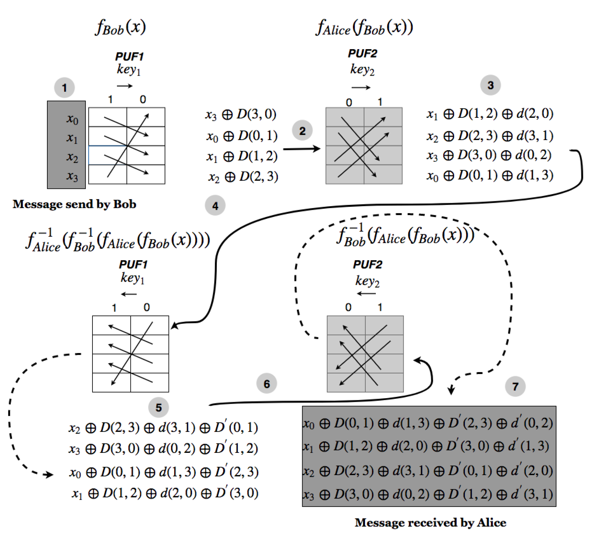
Encrypting without a shared key is ideal. In the first version of the design, each PUF f P U F 1 and f P U F 2 is a permutation network keyed by k e y 1 and k e y 2 , respectively. Key k e y 1 selects a permutation π k e y 1 from a large set of possible permutations—Keccak permutation [20,21] could be used for instance. The implementation, however, needs to be physically and logically reversible consisting of transmission gates. We assume that, for a permutation π k e y 1 which maps ith input bit to the i th output bit and jth input bit to j th output bit, we capture the exact delays for each input-output path. Let D ( i , i ) denote the delay of the path from input i to output i for π k e y 1 in f P U F 1 . Let D ( j , j ) be defined likewise. We will describe how we can capture these delays by using timer capture and edge detector functions in Section 5.
For each PUF, the output bit y i can be expressed as an entanglement function e ( x π k e y - 1 ( j ) , D ( π k e y - 1 ( j ) , j ) ) . Here, e is an entanglement function between the input bit x π k e y - 1 ( j ) routed to output j and the delay of this path from π k e y - 1 ( j ) to j. The delay D ( π k e y - 1 ( j ) , j ) can be quantized to any resolution of k bits. If we use all of the k bits of D ( π k e y - 1 ( j ) , j ) to do encryption at the jth output bit, we expand the n-bit input to an n k -bit output. Assuming we want to retain the same output resolution of n-bits, one option would be to perform an XOR (⊕) of the mth bit of D ( π k e y - 1 ( j ) , j ) with the input bit x π k e y - 1 ( j ) to generate y j leading to the entanglement function y j = e ( x π k e y - 1 ( j ) , D ( π k e y - 1 ( j ) , j ) m ) . XOR is a good choice because it is commutative and associative. Figure 3 shows a encryption flow chart using XOR as the entanglement function. Since the least significant bit (LSB) and 2nd LSB of D ( π k e y - 1 ( j ) , j ) is likely least correlated with the delay of other paths, we have used them in entanglement. The corresponding simulation results are shown in Section 6.
Let us assume that the delays of the permutation function π k e y 1 in f P U F 1 are denoted by D ( π k e y 1 - 1 ( j ) , j ) for a path from input π k e y 1 - 1 ( j ) to output j and the delays of the permutation function π k e y 2 in f P U F 2 are denoted by d ( j , π k e y 2 ( j ) ) for a path from input j to output π k e y 2 ( j ) . Assume that π k e y 1 - 1 ( j ) = i , π k e y 2 ( j ) = k ; then, the output z k = ( x i D ( i , j ) m ) d ( j , k ) m is generated. The mth least significant bit of P U F 2 ’s delay captured by the d function is XORed with f P U F 1 ’s output.
Clearly, the RHS of expression z k = ( x i D ( i , j ) m ) d ( j , k ) m is commutative due to commutativity of operator ⊕—it does not matter whether f P U F 1 is applied first or f P U F 2 is applied first. However, this commutativity statement is only correct for a specific bit routing; it does not apply to encrypted data.
In the following examples, we use a “shift” function instead of an arbitrary permutation. A “shift” function is denoted as π = ( i 0 , i 1 , , i n - 1 ) , which means that bit 0 goes to bit position i 0 or 0 i 0 ; 1 i 1 ; ; ( n - 1 ) i n - 1 . For Bob’s PUF, with permutation π = ( i 0 , i 1 , , i n - 1 ) , the delay for a path from input bit position l to output bit position i l ( l i l ) is quantized as D ( l , i l ) . The mth bit of this quantized delay is denoted as D ( l , i l ) m . Similarly, for Alice’s PUF, with permutation π = ( j 0 , j 1 , , j n - 1 ) d ( l , j l ) m represents the mth bit of the quantized delay for path l j l . Note that, in the following protocol, we do not specify which mth bit of the delay is used for entanglement. We will decide that later based on experimental entropy and reproducibility of the delay bits.
Consider P U F 1 with π k e y 1 = ( 0 1 , 1 2 , 2 3 , 3 0 ) for a 4-bit input x 0 , x 1 , x 2 , x 3 and P U F 2 with π k e y 2 = ( 0 2 , 1 3 , 2 0 , 3 1 ) . Composition of f P U F 1 f P U F 2 = ( 0 1 , 1 2 , 2 3 , 3 0 ) ( 0 2 , 1 3 , 2 0 , 3 1 ) = ( 0 3 , 1 0 , 2 1 , 3 2 ) . By going over the communication protocol in Figure 1 step by step, a defect becomes apparent. The complete verification process is shown in Figure 4.
  • Step 1: Apply f P U F 1 to ( x 0 , x 1 , x 2 , x 3 ) resulting in ( 1 , 2 , 3 , 0 ) ( x 0 , x 1 , x 2 , x 3 ) , which equals ( x 3 D ( 3 , 0 ) m , x 0 D ( 0 , 1 ) m , x 1 D ( 1 , 2 ) m , x 2 D ( 2 , 3 ) m ) .
  • Step 3: Apply f P U F 2 to f P U F 1 ’s output as in ( 2 , 3 , 0 , 1 ) ( 1 , 2 , 3 , 0 ) ( x 0 , x 1 , x 2 , x 3 ) . This equals ( x 1 D ( 1 , 2 ) m d ( 2 , 0 ) m , x 2 D ( 2 , 3 ) m d ( 3 , 1 ) m , x 3 D ( 3 , 0 ) m d ( 0 , 2 ) m , x 0 D ( 0 , 1 ) m d ( 1 , 3 ) m ) .
  • Step 5: Now invert the output. Apply f P U F 1 - 1 to ( 2 , 3 , 0 , 1 ) ( 1 , 2 , 3 , 0 ) ( x 0 , x 1 , x 2 , x 3 ) . f P U F 1 - 1 results in ( 1 , 2 , 3 , 0 ) - 1 ( 2 , 3 , 0 , 1 ) ( 1 , 2 , 3 , 0 ) ( x 0 , x 1 , x 2 , x 3 ) , which equals ( x 2 D ( 2 , 3 ) m d ( 3 , 1 ) m D ( 0 , 1 ) m , x 3 D ( 3 , 0 ) m d ( 0 , 2 ) m D ( 1 , 2 ) m , x 0 D ( 0 , 1 ) m d ( 1 , 3 ) m D ( 2 , 3 ) m , x 1 D ( 1 , 2 ) m d ( 2 , 0 ) m D ( 3 , 0 ) m ) . D ( i , i ) denotes the backward path delay from output i to input i. According to post-layout simulations, D ( i , i ) is always equal to D ( i , i ) in BS-PUFs.
  • Step 7: Further applying f P U F 2 - 1 as in ( 2 , 3 , 0 , 1 ) - 1 ( 1 , 2 , 3 , 0 ) - 1 ( 2 , 3 , 0 , 1 ) ( 1 , 2 , 3 , 0 ) ( x 0 , x 1 , x 2 , x 3 ) results in ( x 0 D ( 0 , 1 ) m d ( 1 , 3 ) m D ( 2 , 3 ) m d ( 0 , 2 ) m , x 1 D ( 1 , 2 ) m d ( 2 , 0 ) m D ( 3 , 0 ) m d ( 1 , 3 ) m , x 2 D ( 2 , 3 ) m d ( 3 , 1 ) m D ( 0 , 1 ) m d ( 2 , 0 ) m , x 3 D ( 3 , 0 ) m d ( 0 , 2 ) m D ( 1 , 2 ) m d ( 3 , 1 ) m ) . This logical result is correct in routing x i back to the ith bit position, but the physical delay terms are completely mixed up and do not cancel each other.

3.2.1. Revised Asymmetric Encryption

In order to ensure the correct routing and commutativity, we modify the original permutation protocol by adding a permutation after each PUF. The primary function of this permutation is routing x i back to the ith position from position π k e y 1 ( i ) before sending the message at the end of Step 1. The complementary key, k e y 1 ¯ , that results in the permutation π k e y 1 - 1 is used; it routes bits back to their original position. Mathematically, ( π k e y 1 ( π k e y 1 ¯ = π k e y 1 - 1 ) ) = 1 where 1 is the identity permutation. Bit shifting to restore the original message bit order is the only function of this permutation. No delay is added.
An example of this protocol is shown in Figure 5 with the following detailed description:
  • Step 1: f B o b permutes x 0 , x 1 , x 2 , x 3 as in ( 1 , 2 , 3 , 0 ) ( x 0 , x 1 , x 2 , x 3 ) . It computes the physical delay encrypted bit vector, ( x 3 D ( 3 , 0 ) m , x 0 D ( 0 , 1 ) m , x 1 D ( 1 , 2 ) m , x 2 D ( 2 , 3 ) m ) . Before sending it to Alice, Bob’s complementary permutation, called permutator in Figure 5 is applied to generate ( x 0 D ( 0 , 1 ) m , x 1 D ( 1 , 2 ) m , x 2 D ( 2 , 3 ) m , x 3 D ( 3 , 0 ) m ) .
    In this new permutation protocol, the logical permutation adds no confusion unlike the permutations in AES and Keccak protocols. Confusion is achieved by the permuted physical delay properties of the PUF. Which path delay bits are combined with each input bit is hidden (through confusion) from the adversary through k e y driven π .
  • Step 3: f A l i c e is applied as ( 2 , 3 , 0 , 1 ) ( x 0 D ( 0 , 1 ) m , x 1 D ( 1 , 2 ) m , x 2 D ( 2 , 3 ) m , x 3 D ( 3 , 0 ) m ) , resulting in ( x 2 D ( 2 , 3 ) m d ( 2 , 0 ) m , x 3 D ( 3 , 0 ) m d ( 3 , 1 ) m , x 0 D ( 0 , 1 ) m d ( 0 , 2 ) m , x 1 D ( 1 , 2 ) m d ( 1 , 3 ) m ) . Applying Alice’s complementary permutation results in ( x 0 D ( 0 , 1 ) m d ( 0 , 2 ) m , x 1 D ( 1 , 2 ) m d ( 1 , 3 ) m , x 2 D ( 2 , 3 ) m d ( 2 , 0 ) m , x 3 D ( 3 , 0 ) m d ( 3 , 1 ) m ) .
  • Step 5: Apply f B o b - 1 to ( x 0 D ( 0 , 1 ) m d ( 0 , 2 ) m , x 1 D ( 1 , 2 ) m d ( 1 , 3 ) m , x 2 D ( 2 , 3 ) m d ( 2 , 0 ) m , x 3 D ( 3 , 0 ) m d ( 3 , 1 ) m ) .
    Decryption follows a similar process. However, the direction of message transmission is reversed and the inverse permutations are used. Physical invertibility recovers the original forward delay vector in the reverse direction.
    Thus, ( 1 , 2 , 3 , 0 ) ( 2 , 3 , 0 , 1 ) ( x 0 , x 1 , x 2 , x 3 ) ) is rearranged by Bob’s permutator first. This is ( x 3 D ( 3 , 0 ) m d ( 3 , 1 ) m , x 0 D ( 0 , 1 ) m d ( 0 , 2 ) m , x 1 D ( 1 , 2 ) m d ( 1 , 3 ) m , x 2 D ( 2 , 3 ) m d ( 2 , 0 ) m ) . This rearranged result is given to to P U F 1 resulting in ( x 0 D ( 0 , 1 ) m d ( 0 , 2 ) m D ( 0 , 1 ) m , x 1 D ( 1 , 2 ) m d ( 1 , 3 ) m D ( 1 , 2 ) m , x 2 D ( 2 , 3 ) m d ( 2 , 0 ) m D ( 2 , 3 ) m , x 3 D ( 3 , 0 ) m d ( 3 , 1 ) m D ( 3 , 0 ) m ) .
    Transmission gates show symmetric delays for forward and backward paths; D ( i , j ) always equals D ( i , j ) . Thus, the delay terms cancel. The result after applying f B o b - 1 is equal to ( x 0 d ( 0 , 2 ) m , x 1 d ( 1 , 3 ) m , x 2 d ( 2 , 0 ) m , x 3 d ( 3 , 1 ) m ) .
  • Step 7: f A l i c e - 1 is applied. First, Alice’s permutator will rotate the bits giving ( x 2 d ( 2 , 0 ) m , x 3 d ( 3 , 1 ) m , x 0 d ( 0 , 2 ) m , x 1 d ( 1 , 3 ) m ) . Rotated bits are then given to P U F 2 in the reverse direction resulting in ( x 0 d ( 0 , 2 ) m d ( 0 , 2 ) m , x 1 d ( 1 , 3 ) m d ( 1 , 3 ) m , x 2 d ( 2 , 0 ) m d ( 2 , 0 ) m , x 3 d ( 3 , 1 ) m d ( 3 , 1 ) m ) . The delay terms cancel. Alice receives the original message ( x 0 , x 1 , x 2 , x 3 ) sent by Bob.
The original protocol in Section 3.2 subtracted the delay from the incorrect bit in the inverse permutation. The protocol shown in this section solves the original problem. However, it contains a fatal flaw; using ⊕ for entanglement creates a linear relationship between messages in-flight between Bob and Alice. An eavesdropper can retrieve the original message from the in-flight messages.
Consider Figure 5 as an example. The first bit in original message is x 0 . The encrypted first bit sent from Bob to Alice in Step 2 is B = x 0 D ( 0 , 1 ) . Then, from Alice to Bob in Step 4, B = x 0 D ( 0 , 1 ) d ( 0 , 2 ) . The decrypted first bit sent from Bob to Alice in Step 6 is B = x 0 d ( 0 , 2 ) . B , B and B are all public messages. An eavesdropper can extract the original message by:
  • Inferring Bob’s PUF delay information by taking XOR of B and B . B B = x 0 D ( 0 , 1 ) d ( 0 , 2 ) x 0 d ( 0 , 2 ) = D ( 0 , 1 ) .
  • Then the original message can be extracted by an XOR of B and Bob’s PUF’s delay, B D ( 0 , 1 ) = x 0 D ( 0 , 1 ) D ( 0 , 1 ) = x 0 .
In order to eliminate this problem, BS-PUF must permute bits in public messages, which we could not do and yet preserve commutativity and invertibility. One possible solution that allows permuted public messages while preserving commutativity and invertibility is to let Bob and Alice share the same key.

3.2.2. Symmetric Encryption

BS-PUF must preserve plaintext message bit positions in the ciphertext to meet the commutativity requirement of encryption protocol with no shared key. Otherwise, the bit delay vector cannot be recovered correctly. The shift permutation is deployed for generating quantized physical delays. If the ciphertext message bits are permuted, they present a stronger challenge for man-in-the-middle attacks. In order to deploy permuted public messages, Bob and Alice must share the same key. The corresponding protocol is shown in Figure 6.
A key sharing protocol such as Diffie–Hellman key exchange scheme can be used to share a secret as needed in the following symmetric encryption protocol. In the symmetric encryption protocol, Bob permutes the input message with π entangling it with his delay. Alice reverses the permutation using π - 1 entangling it with her delay. Thus, the bits are in their original positions in the message sent to Bob for decryption. Note that entanglement with both PUFs’ delays protects this message. The delay will be un-entangled from the correct bits in the subsequent decryption steps.
Details of the shared key scheme presented in Figure 6 are as follows:
  • Step 1: Bob permutes x 0 , x 1 , x 2 , x 3 with π = ( 1 , 2 , 3 , 0 ) and gets ( x 3 D ( 3 , 0 ) m , x 0 D ( 0 , 1 ) m , x 1 D ( 1 , 2 ) m , x 2 D ( 2 , 3 ) m ) . It is sent to Alice without any further bit-level routing; this achieves bit-level confusion of the public message.
  • Step 3: f A l i c e performs the reverse permutation π - 1 of f B o b and simultaneously applies Alice’s delay ( π - 1 = ( 3 , 0 , 1 , 2 ) ). After f A l i c e is applied, all bits are rotated back to their original position, but each bit is encrypted with two physical delay values. In this example, after applying f A l i c e , we get ( x 0 D ( 0 , 1 ) m d ( 1 , 0 ) m , x 1 D ( 1 , 2 ) m d ( 2 , 1 ) m , x 2 D ( 2 , 3 ) m d ( 3 , 2 ) m , x 3 D ( 3 , 0 ) m d ( 0 , 3 ) m ) .
  • Step 5: f B o b - 1 is applied. Permutation π is applied again and the delay added in Step 1 is negated by XOR. Then, the message sent to Alice is converted to ( x 3 D ( 3 , 0 ) m d ( 0 , 3 ) m D ( 3 , 0 ) m , x 0 D ( 0 , 1 ) m d ( 1 , 0 ) m D ( 0 , 1 ) m , x 1 D ( 1 , 2 ) m d ( 2 , 1 ) m D ( 1 , 2 ) m , x 2 D ( 2 , 3 ) m d ( 3 , 2 ) m D ( 2 , 3 ) m ) , which is ( x 3 d ( 0 , 3 ) m , x 0 d ( 1 , 0 ) m , x 1 d ( 2 , 1 ) m , x 2 d ( 3 , 2 ) m )
  • Step 7: f A l i c e - 1 is applied, bit positions are rotated back again, and the delay added in Step 3 is negated by XOR. The message from the previous step is converted to ( x 0 d ( 1 , 0 ) m d ( 1 , 0 ) m , x 1 d ( 2 , 1 ) m d ( 2 , 1 ) m , x 2 d ( 3 , 2 ) m d ( 3 , 2 ) m , x 3 d ( 0 , 3 ) m d ( 0 , 3 ) m ) , which equals the original message x 0 , x 1 , x 2 , x 3 .
Evaluating all messages crossing the insecure channel, M = ( x 3 D ( 3 , 0 ) m , x 0 D ( 0 , 1 ) m , x 1 D ( 1 , 2 ) m , x 2 D ( 2 , 3 ) m ) , M = ( x 0 D ( 0 , 1 ) m d ( 1 , 0 ) m , x 1 D ( 1 , 2 ) m d ( 2 , 1 ) m , x 2 D ( 2 , 3 ) m d ( 3 , 2 ) m , x 3 D ( 3 , 0 ) m d ( 0 , 3 ) m ) , M = ( x 3 d ( 0 , 3 ) m , x 0 d ( 1 , 0 ) m , x 1 d ( 2 , 1 ) m , x 2 d ( 3 , 2 ) m ) .
Linear equations such as M M do not reveal any useful information due to the additional shifting performed using the shared key. There is no way to retrieve the original message from the in flight messages without the shared key and access to Bob and Alice’s PUFs. All messages are protected while traversing the insecure channel.

4. Barrel Shifter PUF Design

We evaluate a barrel shifter as a potential invertible and commutative PUF. The block diagram of a barrel shifter is shown in Figure 7. For simplicity, only two shift levels are shown. In a BS-PUF, text (plaintext/ciphertext) input are the bits to be shifted; the key input determines the shift path for the text input.
Output logic is added to capture path delay D ( i , i ) . An event counter is initialized to 0. The RST signal simultaneously starts the event counter and releases the input message. The delay is captured by reading the event counter when the output logic detects a voltage transition. Finally, an entanglement block in the output logic entangles delay with the message bit.
Each shift stage is logically similar to an arbiter PUF stage. Barrel shifter PUF is designed to implement rotation functions. Key bits determine the shift amount s = i = 0 k ( k e y i e s 2 i ) . Thus, k e y i is applied from LSB to MSB, from left to right. Figure 7 provides an example; k e y = { k e y 0 = 0 , k e y 1 = 1 } encodes for right shift by 2 in the second stage. Consequently, the same text bit traverses a different path providing a different delay value for different keys.
The delay variation is generated by transistor-level mismatch and doping variability. Variation accumulates over several stages. Delay is then large enough to be detected by the output logic.

5. Circuit Implementation

An invertible and commutative PUF based on a barrel shifter is implemented in Cadence Spectre. Transmission gates implement the shift paths. The circuit is subdivided into three components: input logic, shift unit, and output logic.

5.1. Input Logic

Input logic is used to trigger the delay test system. It is a 3-input, 1-output circuit connecting the input signal S or its inverse S ¯ to the output terminal (Figure 8a).
RST (reset) is used to control ON/OFF status. When RST is high, S travels through the first gate and arrives at an intermediate node. Otherwise, it is blocked. REV (reverse) determines whether S is inverted. S will be inverted when REV = 1. The output of input logic should be RST ∧ (REVS).

5.2. Shift Unit

Shift units implement the path selection and form shift stages. A shift unit schematic is shown in Figure 8b. Either inputA or inputB is mapped to the output. The mapping is determined by the key. A key value of 1 causes the upper transmission gate to open; output then becomes inputA. Otherwise, output is driven by inputB.
A sequence of shift unit transmission gates composes a delay path. Each unit has a unique delay, making the delay of each path unique.
BS-PUF uniqueness depends on how much delay variation is provided by the same path on different chips. Modifying the transistor area is the main method for increasing the inter-chip variation. Transistor delay variation is inversely proportional to transistor area [22]. Sizing transistors smaller results in increased delay variation. However, BS-PUF requires a plaintext independent path delay to maintain physical commutativity (Section 6.5). It is hard to balance 0 and 1 transmission delay with minimum sized transistors. The minimum transistor size that preserves the physical commutativity is obtained from Cadence Monte Carlo Simulation.

5.3. Output Logic

Output logic measures and captures path delay. Output logic for each bit contains three parts: Counter, Edge Detector Pulse Generator, and Entanglement Logic.
Counter takes CLK and RST as input producing a 10-bit output; it counts the number of rising edges of CLK. Setting RST high resets the counter to 0. The path delay is expressed as (input clock period) e s (counter value).
Edge Detector Pulse Generator generates a pulse in response to a voltage transition at its input. It includes an edge detector and a pulse generator. The edge detector converts a rising or falling edge into a rising edge at its output. The pulse generator converts the rising edge from edge detector into a pulse.
The output logic works as follows: first, a rising/falling edge at input produces a pulse at the Edge Detector Pulse Generator output. This pulse enables the transmission gate in Figure 9 for a short time period (2 ns). During this time, the counter output is captured; it must not change while being captured. Thus, enable time period must be shorter than clock period (4 ns).
Finally, Entanglement Logic takes the mth LSB of delay D ( i , i ) . Computing XOR of this bit with the input signal x i results in the entangled output bit.
The output logic works by detecting a voltage transition. A voltage transition occurs when the current text bit differs from the previous text bit value. Thus, the output logic is incapable of detecting unchanging/stationary text values. A voltage transition is forced by providing x i ¯ before x i at the text input.

5.4. Path Delay Testing

The input logic, shift unit and output logic work together to capture the path delay. The following five steps are necessary—the five steps shown in Figure 10 are necessary.
  • Set x i ¯ as text input and reset input logic.
  • Wait for x i ¯ to arrive at output logic.
  • Reset input logic and clock counter, set x i as text input.
  • Wait as x i travels the path determined by the k e y , triggering a transition at the output logic.
  • Encrypt using the captured counter value.

6. Post-Layout Simulation Results

The entanglement logic utilizes a 1-bit result from the path delay. The path delay capture logic provides a multiple-bit delay counter. One bit must be chosen; it must be shown to have the requisite properties for BS-PUF [23]: (1) inter-chip variability; (2) intra-chip reproducibility; (3) randomness; (4) commutativity.
Cadence Spectre simulations are used to generate raw delay data. Delay variability assessment is conducted by 3 σ Monte Carlo sampling over process parameters. This test uses IBM 130 nm PDK. A common centroid layout is employed to reduce linear gradient errors.
We construct an eight-stage barrel shifter accepting a 256-bit input with a 256-bit output. Path delay is captured at the resolution of the counter’s clock period; a period of 4 ns is used. Delays must be a reasonable multiple of the clock period to express variation.
In the following experiments, we primarily focus on raw data: (1) 200 Monte Carlo samples of the path from input 0 to output 16, (2) 200 Monte Carlo samples of all 256 paths with no shifting.

6.1. Inter-Chip Variability

Shift path delay is a function of the silicon fabrication process; it potentially exhibits PUF properties. Each shift path terminates with entanglement logic. A bit from the delay counter must be selected. The chosen bit must exhibit sufficient variation.
Monte Carlo simulation captures single path delay variability as a proxy for inter-chip delay variability. In 200 Monte Carlo samples for process parameters along the path x 0 y 16 , the delay ranges from 85 ns to 145 ns with an average around 120 ns. It is a ± 25 % (±30 ns) variation. Counter output varies about ± 8 . This indicates that roughly the least significant three bits of delay have significant entropy in inter-PUF measurements. Thus, the LSB, 2nd LSB, and 3rd LSB are candidates for entanglement.

6.2. Intra-Chip Reproducibility

The robustness of a single PUF is predicated on the consistency of its response to a challenge. The response should be the same regardless of the environment. Tests are performed subjecting BS-PUF to: (1) temperature variation and (2) voltage supply variation. The frequency of response bit flips is quantified.
Bit flip rate is the frequency of bit changes from 0 1 or 1 0 . It is computed relative to a baseline response. Gathering responses at common room temperature (25 C) and supply voltage (5 V) establishes this baseline. The percentage of path delays where a bit flips is the bit flip rate. For example, the LSB flipping in 64/256 paths represents a 25 % bit flip rate.
Path delays for all 256 bit paths are gathered with Monte Carlo sampling under different temperatures and supply voltages. Temperature is varied from 0 C to 50 C and supply voltage from 4.64 V to 5 V. The corresponding test results are shown in Figure 11 and Figure 12. Flip rates for the 2nd LSB are smaller than 12 % and 18 % under temperature and voltage variation, respectively. On the contrary, the flip rate of the LSB is significantly higher. The 2nd LSB provides better reproducibility. By taking 2nd LSB, the stability performance of BS-PUF is similar to traditional RO-PUFs [24].
Usually, an error caused by PUF reproducibility can be resolved by error correction code (ECC) [25]. ECC implementations usually need 3k–10k raw PUF response bits (with bit error rate of 15 % ) to a 128-bit reproducible PUF response with a targeted key error rate less than 10 6 [26]. This implies that we need to provide 23–80 raw bits to generate one single reproducible bit. The instability of BS-PUF responses ( 18 % ) can also be compensated by generating a sufficient number of redundant bits. For instance, an error detection capability based on the parity bits, as deployed in communication protocols, could be incorporated into the encryption protocol. For a 128-bit message, nine additional parity bits—one for each byte—can be computed. The actual message block to be encrypted is the concatenation of the 128-bit message with nine parity bits, resulting in a 137-bit message block. After the proposed encryption protocol delivers a message to the receiver, it also computes the parity bits on the 128-bit message part. These computed parity bits are then compared against the received parity bits. If there is an error, the receiver can ask the sender to resend the message. The error correction overhead can be reduced by developing some stable keyed-PUF in the future.
A higher order bit could be selected. It would have comparatively better flip rates, but reduced variability. Many feasible techniques exist to compensate for temperature and voltage variation [27,28]. These techniques would be helpful at the flip rates expressed by the 2nd LSB. Thus, the advantage of choosing a higher order bit is minimal. All of the following evaluations are performed on the 2nd LSB only.

6.3. Inter-Chip Uniqueness

The chosen path delay bit must exhibit inter-chip uniqueness. This requires significant variance between responses on different chips. Pair-wise hamming distance (HD) is a metric for variability.
The HD of 200 path delay samples of 256-bit responses is computed. Table 1 shows the distribution of inter-chip HD for 2nd LSB output.
The mean HD is 128 . 01 bits with a standard deviation of 9 . 99 bits. HD 128 means that roughly 50 % of the response bits differ. It is maximally unlikely that two BS-PUFs will generate the same output.

6.4. Randomness

Output of a good PUF should look like a pseudo-random generator so an attacker cannot model it easily. Assessing randomness performance of BS-PUF uses data from Monte Carlo sampling of path delays. Delay values are converted to binary responses by extracting the 2nd LSB from the delay. Each 256-bit response (one bit from each path) is examined using an NIST statistical test suite.
Table 2 give the detailed test results for 2nd LSB of the BS-PUF output. The minimum pass rate for each statistical test is 193 for a sample size of 200 binary sequences according to NIST documentation. The 2nd LSB passes the randomness test; a proportion greater than 193 is achieved on all selected tests.

6.5. Commutativity

Encryption and decryption rely on function composition. Decrypting a message encrypted by both oneself and another party is required. The other party may have changed the text bit (0 or 1). Thus, delay variation must be independent from the text input. The transmission delay of 1 and 0 should not have a significant difference.
BS-PUF path delays depend only on the key input. Shift units are sized to achieve balanced pullup and pulldown resistance. Transmission gate NMOS sizing is W n / L n = 4 / 3 PMOS sizing is W p / L p = 4 / 1 , where L n = L p .
Two tests are performed to verify physical commutativity of BS-PUF: (1) Testing rising/falling edge delay in four different (FF, FS, SF, SS) process corners. Transmission time difference for 0 and 1 must be smaller than the counter period (4 ns); (2) Performing Monte Carlo sampling of path delay for inputs 0 and 1. Delays are recorded for all paths without bit shifting. No bit flips should occur in the path delay.
According to corner test results, maximum transmission time difference for 0 and 1 is 2.34 ns; this is much smaller than the 4 ns clock period. Consequently, there are no 2nd LSB flips in Monte Carlo sampling.

7. Modeling Attack

According to [29], all examined strong PUFs under a given size can be modeled with machine learning with success rates above their stability in silicon. Stability in silicon captures the rate at which a response can be reproduced faithfully for a given challenge. It models the native noise inherent in a PUF design. Modeling attacks cannot overcome the inherent design noise. Consider the barrel shifter in our encryption protocol to be a black box. Attackers know nothing about the key and physical delay of the barrel shifter. An attacker should not be able to model the relationship between input and output bits. Such a model provides an eavesdropper information about the plaintext given a ciphertext.
To investigate the resilience of BS-PUFs against modeling attacks, various ciphertexts are generated with different keys and plaintexts for training and cross-validation.
Logistic Regression (LR) [30] and Evolution Strategies (ES) [31,32] are commonly used to model PUF output. ES is specialized to model PUFs under noisy conditions [29]. It does not apply when voltage supply and temperature are fixed and known.
Thus, only LR modeling is performed. Since the error rate of machine learning prediction decreases with the size of training set, LR modeling is tested for 2nd LSB of the response with various training set sizes.
Monte Carlo Sampling [33] utilizes randomness to generate n challenge response pairs (CRP). n random keys, K = { K 0 , K 1 , , K n } are generated. Responses, R, are generated by entangling plaintext, P, using these keys, R i = B S - P U F ( K i , P ) . The adversary is interested in extracting the delay from the response. Hence, we generate only the delay component in the Monte Carlo samples keeping the same plaintext. This random CRP sample is assumed to be representative of the distribution of all CRPs.
Simulating B S - P U F ( K i , P ) requires computationally expensive Cadence Spectre simulations. An efficient method for computing R i given K i is needed. Thus, we apply Monte Carlo Sampling to create a delay matrix, D, modeling the delay of all shift paths. The delay of each shift unit is recorded. Path delay is then computed by: (1) summing the delay of all shift units along a path, (2) dividing it by 4   ns capture logic resolution, and (3) extracting 2nd LSB (as discussed in Section 6, 2nd LSB is the best candidate). Thus, D enables computations of path delays given K i .
For example, Equation (1) is a sample delay matrix for a 4-input, two-stage BS-PUF. d i , j represents exact delay values of top and bottom transmission gates in the ith row, jth column shift unit:
D = ( d 0 , 0 , t , d 0 , 0 , b ) ( d 0 , 1 , t , d 0 , 1 , b ) ( d 1 , 0 , t , d 1 , 0 , b ) ( d 1 , 1 , t , d 1 , 1 , b ) ( d 2 , 0 , t , d 2 , 0 , b ) ( d 2 , 1 , t , d 2 , 1 , b ) ( d 3 , 0 , t , d 3 , 0 , b ) ( d 3 , 1 , t , d 3 , 1 , b ) .
Plaintext–ciphertext pairs (PCP) are computed using D. For the delay matrix in Equation (1) using a k e y = { 1 , 0 } encoding for right shift in the first stage, the plaintext ( i 0 , i 1 , i 2 , i 3 ) generates the response in Equation (2):
R = i 3 ( ( d 0 , 0 , b + d 0 , 1 , t ) / 4 ) m i 0 ( ( d 1 , 0 , b + d 1 , 1 , t ) / 4 ) m i 1 ( ( d 2 , 0 , b + d 2 , 1 , t ) / 4 ) m i 2 ( ( d 3 , 0 , b + d 3 , 1 , t ) / 4 ) m .
This process makes extraction of all possible PCPs feasible.
For a BS-PUF with an input message length of 256-bit, there are 2 256 possible input messages. There are eight stages with 2 8 possible keys. It is infeasible to generate all 2 264 PCPs. Linear Regression (LR) is performed with a training set of size n = { 10 , 100 , 1000 } PCPs per key. To obtain a representative sample of PCPs, responses are computed with 100 keys and 10 , 000 plaintexts. PCPs not part of the training set are used for cross-validation.
Scalability experiments are conducted on a six-stage, 64-bit input BS-PUF; the delay matrix of this BS-PUF is the top left 64 e s 6 sub-matrix of the eight-stage delay matrix acquired from Monte Carlo Sampling. The number of CRPs N C R P that are required to learn a k-stage arbiter PUF with error rate ϵ is 0 . 5 e s ( k + 1 ) / ϵ [29]. Thus, for a six-stage BS-PUF, we also scale down n to 8, 80 and 800 PCPs per key.
Table 3 shows the prediction accuracy of LR on 2nd LSB. LR is implemented by an iterative program written in Matlab. The regression coefficients’ initial values are set to ( 0 , 0 ) in all LR applications. Silicon stability of BS-PUFs is 75 % . Thus, all modeling reaching a higher prediction rate should be considered a success. If 2nd LSB is used as the delay bit, then LR can successfully model six-stage BS-PUF with a sufficient number of PCPs while eight-stage BS-PUF cannot be successfully modeled without enlarging the training set.

8. Conclusions and Future Work

In this work, we propose an encryption protocol based on invertible and commutative PUFs and propose a circuit implementation of the required invertible and commutative PUF (BS-PUF). Spectre Monte Carlo simulations indicate only less than 1 bit delay variation when the plaintext changes. This ensures the commutativity of the system. The primary focus of this paper is to develop a PUF-based encryption protocol; to define the requirements of such a protocol—an invertible and commutative PUF; and to show that such an invertible and commutative PUF design is feasible. Simulations that establish this PUF design provide good randomness, uniqueness and reproducibility performance. These encryption PUFs have the potential to root encryption in hardware, hence increasing robustness beyond current software-only solutions.
Much needs to be addressed to establish the practicality of invertible and commutative PUFs in real silicon implementations. An evaluation of PUFs based on more relevant permutation families such as the Keccak sponge family [20] is needed. There are many possible future directions to incorporate asymmetric encryption with these PUFs. The proposed design uses raw PUF responses; it will therefore be noisier than traditional PUFs. An error coding scheme using helper data and some form of fuzzy extraction is required.

Author Contributions

Conceptualization, Y.G. and A.T.; Methodology, Y.G., T.D. and A.T.; Software, Y.G.; Validation, Y.G.; Formal Analysis, Y.G., T.D. and A.T.; Investigation, Y.G. and A.T.; Resources, A.T.; Data Curation, T.D. and Y.G.; Writing—Original Draft Preparation, Y.G., T.D. and A.T.; Writing—Review and Editing, Y.G., T.D. and A.T.; Visualization, Y.G. and A.T.; Supervision, A.T.; Project Administration, A.T.; Funding Acquisition, A.T.

Funding

This research received no external funding.

Conflicts of Interest

The authors declare no conflict of interest.

Abbreviations

The following abbreviations are used in this manuscript:
PUFPhysical Unclonable Function
BS-PUFBarrel Shifter Physical Unclonable Function
RO-PUFRing Oscillator Physical Uncloable Function
CBCCipher Block Chaining
IVInitialization Vector
LSBLeast Significant Bit
DFFD Flip-Flop
HDHamming Distance
LRLogistic Regression
ESEvolution Strategies
CRPChallenge Response Pairs
PCPPlaintext–Ciphertext Pairs

References

  1. Boneh, D. Twenty years of attacks on the RSA cryptosystem. Not. AMS 1999, 46, 203–213. [Google Scholar]
  2. Yanambaka, V.P.; Mohanty, S.P.; Kougianos, E.; Singh, J. Secure Multi-Key Generation Using Ring Oscillator based Physical Unclonable Function. In Proceedings of the 2016 IEEE International Symposium on Nanoelectronic and Information Systems (iNIS), Gwalior, India, 19–21 December 2016; pp. 200–205. [Google Scholar]
  3. Chen, Q.; Csaba, G.; Ju, X.; Natarajan, S.; Lugli, P.; Stutzmann, M.; Schlichtmann, U.; Rührmair, U. Analog circuits for physical cryptography. In Proceedings of the 2009 12th International Symposium on Integrated Circuits, Singapore, 14–16 December 2009; pp. 121–124. [Google Scholar]
  4. Choi, W.; Kim, S.; Kim, Y.; Park, Y.; Ahn, K. PUF-based Encryption Processor for the RFID Systems. In Proceedings of the 2010 10th IEEE International Conference on Computer and Information Technology, Bradford, UK, 29 June–1 July 2010; pp. 2323–2328. [Google Scholar]
  5. Devadas, S.; Suh, E.; Paral, S.; Sowell, R.; Ziola, T.; Khandelwal, V. Design and implementation of PUF-based “unclonable” RFID ICs for anti-counterfeiting and security applications. In Proceedings of the 2008 IEEE International Conference on RFID, Las Vegas, NV, USA, 16–17 April 2008; pp. 58–64. [Google Scholar]
  6. Che, W.; Saqib, F.; Plusquellic, J. PUF-based authentication. In Proceedings of the 2015 IEEE/ACM International Conference on Computer-Aided Design (ICCAD), Austin, TX, USA, 2–6 November 2015; pp. 337–344. [Google Scholar]
  7. Urbi Chatterjee, R.S.C.; Mukhopadhyay, D. A PUF-Based Secure Communication Protocol for IoT; Cryptology ePrint Archive, Report 2016/674; ACM: New York, NY, USA, 2016; Available online: http://eprint.iacr.org/2016/674 (accessed on 30 August 2018).
  8. Yanambaka, V.P.; Mohanty, S.P.; Kougianos, E. Novel FinFET based physical unclonable functions for efficient security integration in the IoT. In Proceedings of the 2016 IEEE International Symposium on Nanoelectronic and Information Systems (iNIS), Gwalior, India, 19–21 December 2016; pp. 172–177. [Google Scholar]
  9. Yanambaka, V.P.; Mohanty, S.P.; Kougianos, E.; Sundaravadivel, P.; Singh, J. Reconfigurable Robust Hybrid Oscillator Arbiter PUF for IoT Security Based on DL-FET. In Proceedings of the 2017 IEEE Computer Society Annual Symposium on VLSI (ISVLSI), Bochum, Germany, 3–5 July 2017; pp. 665–670. [Google Scholar]
  10. Kleber, S.; Unterstein, F.; Matousek, M.; Kargl, F.; Slomka, F.; Hiller, M. Secure Execution Architecture based on PUF-driven Instruction Level Code Encryption. IACR Cryptol. ePrint Arch. 2015, 2015, 651. [Google Scholar]
  11. Daemen, J.; Rijmen, V. The Design of Rijndael: AES-the Advanced Encryption Standard; Springer: Berlin, Germany, 2013. [Google Scholar]
  12. Holcomb, D.E.; Burleson, W.P.; Fu, K. Power-up SRAM state as an identifying fingerprint and source of true random numbers. IEEE Trans. Comput. 2009, 58, 1198–1210. [Google Scholar] [CrossRef]
  13. Mansouri, S.S.; Dubrova, E. Ring oscillator physical unclonable function with multi level supply voltages. In Proceedings of the 2012 IEEE 30th International Conference on Computer Design (ICCD), Montreal, QC, Canada, 30 September–3 October 2012; pp. 520–521. [Google Scholar]
  14. Yin, C.E.D.; Qu, G. LISA: Maximizing RO PUF’s secret extraction. In Proceedings of the 2010 IEEE International Symposium on Hardware-Oriented Security and Trust (HOST), Anaheim, CA, USA, 13–14 June 2010; pp. 100–105. [Google Scholar]
  15. Maiti, A.; Schaumont, P. Improving the quality of a physical unclonable function using configurable ring oscillators. In Proceedings of the 2009 International Conference on Field Programmable Logic and Applications, Prague, Czech Republic, 31 August–2 September 2009; pp. 703–707. [Google Scholar]
  16. Maiti, A.; Schaumont, P. Improved ring oscillator PUF: An FPGA-friendly secure primitive. J. Cryptol. 2011, 24, 375–397. [Google Scholar] [CrossRef]
  17. Hori, Y.; Yoshida, T.; Katashita, T.; Satoh, A. Quantitative and statistical performance evaluation of arbiter physical unclonable functions on FPGAs. In Proceedings of the 2010 International Conference on Reconfigurable Computing and FPGAs, Quintana Roo, Mexico, 13–15 December 2010; pp. 298–303. [Google Scholar]
  18. Tajik, S.; Dietz, E.; Frohmann, S.; Seifert, J.P.; Nedospasov, D.; Helfmeier, C.; Boit, C.; Dittrich, H. Physical characterization of arbiter PUFs. In Proceedings of the International Workshop on Cryptographic Hardware and Embedded Systems, Busan, Korea, 23–26 September 2014; Springer: Berlin, Germany, 2014; pp. 493–509. [Google Scholar]
  19. Bennett, C.H.; Landauer, R. The fundamental physical limits of computation. Sci. Am. 1985, 253, 48–56. [Google Scholar] [CrossRef]
  20. Bertoni, G.; Daemen, J.; Peeters, M.; Van Assche, G. The Keccak Sponge Function Family; Technical Report; Team Keccak: Gaithersburg, MD, USA, 2016. [Google Scholar]
  21. Bertoni, G.; Daemen, J.; Peeters, M.; Van Assche, G. The Keccak Reference. Available online: https://keccak.team/files/Keccak-reference-3.0.pdf (accessed on 30 August 2018).
  22. Grünebaum, U.; Oehm, J.; Schumacher, K. Mismatch modeling and simulation? A comprehensive approach. Analog Integr. Circuits Signal Process. 2001, 29, 165–171. [Google Scholar] [CrossRef]
  23. Joshi, S.; Mohanty, S.P.; Kougianos, E. Everything You Wanted to Know about PUFs. IEEE Potentials 2017, 36, 38–46. [Google Scholar] [CrossRef]
  24. Gao, M.; Lai, K.; Qu, G. A highly flexible ring oscillator PUF. In Proceedings of the 51st Annual Design Automation Conference, San Francisco, CA, USA, 1–5 June 2014; ACM: New York, NY, USA, 2014; pp. 1–6. [Google Scholar]
  25. Yu, M.D.M.; M’Raihi, D.; Sowell, R.; Devadas, S. Lightweight and secure PUF key storage using limits of machine learning. In Proceedings of the 13th International Workshop on Cryptographic Hardware and Embedded Systems, Nara, Japan, 28 September–1 October 2011; Springer: Berlin, Germany, 2011; pp. 358–373. [Google Scholar]
  26. Bhargava, M.; Mai, K. An efficient reliable PUF-based cryptographic key generator in 65 nm CMOS. In Proceedings of the conference on Design, Automation & Test in Europe, Dresden, Germany, 24–28 March 2014; p. 70. [Google Scholar]
  27. Kumar, R.; Chandrikakutty, H.K.; Kundu, S. On improving reliability of delay based Physically Unclonable Functions under temperature variations. In Proceedings of the 2011 IEEE International Symposium on Hardware-Oriented Security and Trust, San Diego, CA, USA, 5–6 June 2011; pp. 142–147. [Google Scholar]
  28. Vivekraja, V.; Nazhandali, L. Feedback based supply voltage control for temperature variation tolerant PUFs. In Proceedings of the 2011 24th Internatioal Conference on VLSI Design, Chennai, India, 2–7 January 2011; pp. 214–219. [Google Scholar]
  29. Rührmair, U.; Sehnke, F.; Sölter, J.; Dror, G.; Devadas, S.; Schmidhuber, J. Modeling attacks on physical unclonable functions. In Proceedings of the 17th ACM conference on Computer and Communications Security, Chicago, IL, USA, 4–8 October 2010; ACM: New York, NY, USA, 2010; pp. 237–249. [Google Scholar]
  30. Bishop, C.M. Pattern Recognition and Machine Learning; Springer: Berlin, Germany, 2006. [Google Scholar]
  31. Back, T. Evolutionary Algorithms in Theory and Practice: Evolution Strategies, Evolutionary Programming, Genetic Algorithms; Oxford University Press: Oxford, UK, 1996. [Google Scholar]
  32. Schwefel, H.P.P. Evolution and Optimum Seeking: The Sixth Generation; John Wiley & Sons, Inc.: Hoboken, NJ, USA, 1993. [Google Scholar]
  33. Robert, C.P. Monte Carlo Methods; Wiley Online Library: Hoboken, NJ, USA, 2004. [Google Scholar]
Figure 1. Encryption protocol with message encryption based on invertible and commutative PUFs f B o b and f A l i c e .
Cryptography 02 00022 g001
Figure 2. Cipher block chaining methods are used to encrypt (a) and decrypt (b) messages. This prevents the adversary from identifying plaintext patterns; it ensures identical blocks of plaintext encrypt to different ciphertexts.
Cryptography 02 00022 g002
Figure 3. Flowchart of 1-bit encryption; d i ( m ) is the mth bit of signal delay in selected path. This path depends on all bits of key k. Keyed path selection achieves confusion.
Cryptography 02 00022 g003
Figure 4. (1) Bob applies f B o b and (2) sends the result to Alice. (3) Alice applies f A l i c e and (4) sends the result to Bob. (5) Bob applies f B o b - 1 and (6) returns the result to Alice. (7) Alice applies f A l i c e - 1 hoping to recover the message. Unfortunately, f - 1 does not subtract delay from the correct bit in (5,7); the correct message is not received by Alice. This scheme fails to be commutative.
Cryptography 02 00022 g004
Figure 5. Invertible and Commutative PUF protocol: P U F 1 ( f B o b ) and P U F 2 ( f A l i c e ) illustrate the PUF composition and how barrel shifter PUF is used for encryption and decryption processes. Assume both P U F 1 and P U F 2 are two-stage BS-PUFs, k e y 1 ( P U F 1 ) is ( 1 , 0 ) , k e y 2 ( P U F 2 ) is ( 0 , 1 ) . For P U F 1 , bit x 0 ( x 1 ) goes to output bit position y 1 ( y 2 ). The encrypted bit output at y 1 ( y 2 ) is x 0 D ( 0 , 1 ) m ( x 1 D ( 1 , 2 ) m ). D ( i , i ) m is the mth least significant bit of the delay from input bit i to the output bit i . A permutator is added after each PUF to shift each bit back to its original position after encryption.
Cryptography 02 00022 g005
Figure 6. Sharing a key allows both parties to perform the same permutation. This ensures that the delay is subtracted from the correct bit when performing the inverse f P U F n - 1 . Shifting the public message adds entropy.
Cryptography 02 00022 g006
Figure 7. Block diagram of the delay test circuit with two propagation examples. When k e y 0 = 1 and k e y 1 = 0 , i 0 passes through the dark grey path. There is one bit shift at the first level and no shift at second level, i 0 o 1 . When k e y 0 = 0 and k e y 1 = 1 , i 0 passes through the light grey path. There is no shift at the first level and there is a two-bit shift at the second level, i 0 o 2 .
Cryptography 02 00022 g007
Figure 8. (a) schematic of 1-bit input logic. Each input bit is controlled by an input logic unit; (b) shift unit of barrel shifter. If KEY = 1, N1/P1 is on (N2/P2 is off), then output equals i n p u t A ; otherwise, output equals i n p u t B .
Cryptography 02 00022 g008
Figure 9. Schematic of output logic. Edge Detector Pulse Generator is composed of an edge detector and a pulse generator. The edge detector detects a voltage transition; implemented by 2 D Flip-Flops (DFFs). The output of a DFF is high when there is a rising edge at its input. Edge Detector Pulse Generator converts a rising/falling edge at input to a pulse response. This pulse triggers a Counter read and Entanglement Logic activation.
Cryptography 02 00022 g009
Figure 10. The path delay capture unit tests for and stores the path delay. The edge detector detects an o u t p u t transition; S equal to o u t p u t will not be detected. Consequently, the transmission path receives S and S ¯ successively; a transition at o u t p u t is guaranteed.
Cryptography 02 00022 g010
Figure 11. Percentage of bit flips under temperature variation. Flip rates demonstrate signal-to-noise ratio (SNR) under different temperatures. Flip rates of LSB are shown in dark grey. Flip rates of 2nd LSB are shown in grey. The flip rate of LSB is much higher than 2nd LSB.
Cryptography 02 00022 g011
Figure 12. Percentage of bit flips under voltage variation. Flip rates of LSB are shown in dark grey. Flip rates of 2nd LSB are shown in grey.
Cryptography 02 00022 g012
Table 1. Inter-chip HD of BS-PUFs 2nd LSB (HD: Hamming distance; %: percentage of bit-stream pairs with certain HD).
HD [ 90 , 100 ) [ 100 , 110 ) [ 110 , 120 ) [ 120 , 130 )
%0.12%2.57%15.68%37.12%
HD [ 130 , 140 ) [ 140 , 150 ) [ 150 , 160 )
%37.29%6.25%0.97%
Table 2. NIST test results of the 2nd LSB response.
c1c2c3c4c5c6c7c8c9c10p-ValueProportionStatistical Test
152422191517102120370.005166200/200Frequency
121824271526201329160.048716200/200BlockFrequency
11212026162219924320.012650200/200CumulativeSums
152115211818281128250.099513200/200CumulativeSums
222526201820161819160.807412199/200Runs
172022212422181420220.917870197/200Serial
241920192117182514230.825505197/200Serial
Table 3. LR on the 2nd LSB with six- and eight-stage BS-PUFs.
ML MethodBit LengthPrediction RatePCPsTraining Time
LR6443.2%
52.6%
79.5%
800
8000
80,000
0.0315 s
0.1658 s
1.0104 s
LR25632.4%
41.0%
62.8%
1000
10,000
100,000
0.0157 s
0.4620 s
1.6245 s

