1. Introduction
Free electron lasers use ultra-relativistic free electrons traveling in a periodic magnetic field shaped by an undulator as a gain medium [
1,
2].
At present, light sources based on free-electron laser (FEL) facilities offer femtosecond tunable radiation in the domains of Hard X-ray—LCLS [
3], SACLA [
4], PAL-XFEL [
5], SwissFEL [
6], European XFEL [
7]—and of VUV, Soft X-ray—FLASH [
8], FERMI [
9]. Among the recent trends of FEL developments, compact designs are in rapid development in replacing the relevant elements with alternative accelerator concepts or using novel schemes [
10]. Within the EuPRAXIA concept [
11,
12], the interest is to consider a laser plasma based accelerator to drive an FEL.
In this work, the FEL performance is estimated analyzing the full longitudinal behavior of each electron beam distribution, taking account of the proper current, energy and energy spread profiles along the bunch. As it will be discussed, this feature is of particular relevance as the current distribution has peak structures with long asymmetric tails, and as the energy spread distribution exhibits abrupt variations.
When considering to realize an FEL based on electron bunches produced by laser plasma acceleration [
13,
14,
15,
16,
17,
18], several new issues have to be considered [
19,
20]:
the electron beam presents an energy spread inherent to the dynamics of plasma acceleration, which is typically one order of magnitude larger than that generally available at conventional linear accelerators driving FELs;
external injection schemes promise a more reliable control of the beam quality, with emphasis on those effects inducing beam emittance deterioration [
21];
in order to minimize energy spread and divergence increase, a high brightness injector is needed and particular care about bunch length must be taken;
Twiss parameters have to be chosen such that both a decrease of divergence and an increase of size at almost constant emittance take place at undulator entrance.
In the following, we analyze the FEL performance in the self-amplified spontaneous emission (SASE) operation mode of some of the most promising schemes based on laser and particle driven plasma injection. Independently from the acceleration mechanism, we also compare the results of the beams with the same electron mean energy, evaluating the FEL properties when passing through the same undulator configuration.
2. Features of the Electron Beams at Plasma Exit and of the Transfer Line
The main EuPRAXIA objective in terms of beam energy consists of providing electron bunches:
- -
at 1 GeV as a preliminary commissioning step;
- -
at 5 GeV meeting FEL users’ final requirements in terms of wavelength and short pulse duration.
Among the several scrutinized schemes, the following emerge as the most promising ones in terms of beam quality and subsequent efficient light production.
Radio frequency injector and laser plasma acceleration stage. In this scheme [
22], a 500 MeV electron beam is injected through a radio frequency (RF) section [
23] into the plasma acceleration stage which in turn accelerates the electrons up to either a beam distribution with 1 GeV [
24] energy, denoted hereafter as Rossi–1, or a beam distribution with 5 GeV energy, denoted hereafter as Rossi–5.
Laser plasma injector and acceleration. This scheme includes two plasma stages: the laser plasma injector to produce electrons with beam energy of 150 MeV and a laser plasma acceleration stage to have particles with the final energy of 5 GeV. In particular, the beam distribution under study and denoted hereafter as Maynard–5 is injected with the resonant multi-pulse ionization technique [
25,
26] and accelerated through a single stage in the quasilinear regime [
27,
28].
Radio frequency injector and particle-driven plasma acceleration stage. In this scheme, a laser-comb configuration [
29,
30] produces two electron bunches: a 200 pC driver and a 30 pC witness bunch. Both are injected to the plasma acceleration stage which in turn accelerates the witness bunch up to 1 GeV energy [
31]. The resulting beam distribution is denoted hereafter as Marocchino–1.
These beam distributions are analyzed in terms of the main parameters driving the FEL performance. More in detail, the electron distribution slice with the highest current density [
11] is identified and values of emittance, energy spread and peak current are calculated over the width of this slice in order to have reasonable performance predictions. For a quantitative comparison among the beams before any undulator matching consideration,
Table 1 shows the parameter values at plasma exit, where
,
,
and
are values of the normalized emittance in
, the RMS size in
, the peak current and the RMS energy spread calculated over the specified length of the phase space longitudinal sampling
, reasonably chosen on the basis of the electron RMS bunch length
: it results larger than the expected SASE spike length, in each beam case. We emphasize that the current profile is not described with a Gaussian distribution, in any of the electron beam presented here: the width of the beam current pulse is typically shorter than
.
The transfer line from the plasma exit stage, where the bunch leaves strong focusing fields to drift into free space, is designed [
32,
33] such that each electron beam is properly matched to the undulator configurations to be discussed in the following section.
Furthermore, the transfer line also accounts for the following considerations:
the growth of both emittance and energy spread has to be minimized along the line;
the maximum total length is 8 m and the focusing gradients are chosen to be 700 T/m for the permanent magnet and 100 T/m for the electromagnetic quadrupoles.
3. Undulator Line Characteristics
In an FEL, electromagnetic radiation is attained by wiggling the electrons subject to the periodic magnetic field of an undulator, specified by the undulator period
and the deflection strength parameter
K. These quantities define the resonant FEL wavelength
:
where
is the beam energy Lorentz factor,
for planar (helical) undulators,
is the peak magnetic field value, and
e,
and
c are the electron charge, the electron mass and the speed of light, respectively.
The main parameter quantifying FEL performance is the Pierce parameter
[
34].
It depends on undulator parameters and on the bunch current density
j, from which the cooperation length
is derived:
where
is the planar undulator factor, of argument
described in terms of the Bessel
functions of the first kind.
Each previously discussed beam distribution is analyzed and matched to two different undulator configurations [
12], in order to probe the beam phase space features with two different cooperation lengths: one targeting
nm with 5 GeV beam energy, and within present and near future undulator technology [
35,
36] and the other such that
at
GeV and
at
GeV.
Table 2 shows the features of the chosen undulator configurations. These parameters are within capabilities for both superconducting and cryogenic permanent magnet devices, with no need to shrink the undulator gap to 6 mm or less, so that the FEL dynamics in these devices is less affected by wakefield effects. These effects have been neglected in the following calculations. Room temperature undulators are expected to provide weaker
and K values with undulator gap larger than 6 mm, so they are not considered.
At both 1 GeV and 5 GeV energies, the natural focusing of the undulator is rather weak.
In order to maintain a small transverse size of the electron beam, the periodic magnetic cell has to include alternate gradient quadrupoles in between undulator modules.
As an example,
Figure 1 shows the resulting
values as a function of
z when matching the electron beams of
Table 1 to the undulator configuration with
cm and
.
The strategy to match the beams is based on minimizing the difference between average Twiss values, , also featuring reasonable magnetic gradients, for both the short and the long configurations. Undulator period and strength clearly define the Twiss and parameter values that the electron beams should have at the undulator entrance, in order to be correctly matched.
4. FEL Results
After proper transport of the beams through the undulator entrance, the distribution slice with the lowest ratio is identified as the best slice in terms of FEL performance. This slice definition is used to identify parameter values for the semi-analytical calculations.
Table 3 shows the main parameters associated to this slice, within a sampling interval
along the bunch, as previously defined and shown on the last column of
Table 1, for each beam.
In particular, refers to a nominal average Twiss value along the full undulator section and is the normalized emittance, averaged along the bunch. For every beam distribution, the best slice has an emittance value smaller than : for a more conservative estimate, the average emittance is considered. Symmetry in x and y coordinates is assumed for both and .
Compared to the parameters presented in
Table 1, these values refer to a different phase space region, optimized also taking energy spread into account. Moreover, space charge effects induce a non-negligible coupling between longitudinal and transverse planes, resulting in a net bunch decompression for each beam distribution.
Table 3 also shows the cooperation length values expected when matching the electron beams either to the short,
with
cm, or to the long,
with
cm, undulator period configuration.
As a first step, these values are used to estimate the FEL performance by means of semi-analytical formulae [
37,
38,
39,
40,
41]. Within this picture, the main parameters quantifying the FEL performance are gain length
and saturation power
, both depending on the Pierce parameter as in the following:
where
and
are correction functions accounting for energy spread and emittance contributions and
is the power associated to the electron beam.
Then, as a second step, the SASE FEL performance is evaluated with the
PERSEO simulation code [
42], that allows to perform a full time-dependent simulation of the FEL dynamics taking account of the given longitudinal current, energy and energy spread profiles and of their interplay along the bunch. The transverse plane dynamic effects are accounted for via a 3D coupling factor derived from the Ming-Xie relations [
39]. Moreover, the time-dependent analysis allows a reliable estimate of the FEL pulse duration and spectrum line width.
Figure 2 and
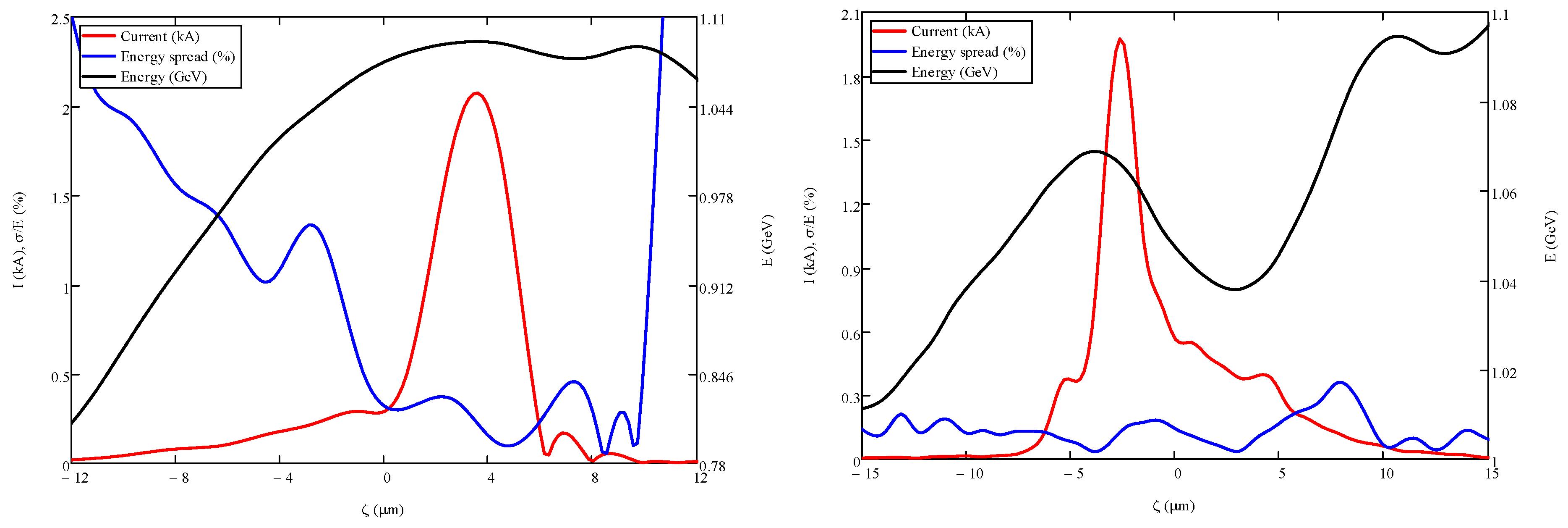
Figure 3 show the longitudinal slice profiles of energy, current, energy spread and normalized emittance, for the 5 GeV and 1 GeV beam distributions respectively.
4.1. Results with the Short Undulator Period Configuration
Table 4 shows the FEL results on gain length and saturation power targeting the short resonant wavelength, and featuring inhomogeneous broadening effects based only on the best slice parameters. The normalized emittance value in Maynard–5, which was higher than in Rossi–5, results in a higher gain length and lower saturation power.
The results of the time-dependent simulations obtained accounting for the proper longitudinal dynamics of each beam distribution are shown in
Table 5. Comparing Maynard–5 and Rossi–5, the different values of the energy spread distributions under the peak current region (as shown in
Figure 2) explain the differences in saturation length and in the number of photons per pulse.
Figure 4 shows the evolution of the SASE FEL energy per pulse, for the beam distributions matched to the short undulator period configuration, for both fundamental and third harmonic. The curves suggest that targeting the shorter resonant wavelength is within reach for 1 GeV beams, while it demands extremely high quality 5 GeV beam distributions, namely very low energy spread and normalized emittance values.
Figure 5 shows the wavelength spectra at saturation of the SASE radiation generated by the electron distributions at 5 GeV and 1 GeV beam energies respectively, traversing the short period undulator line configuration.
4.2. Results with the Long Undulator Period Configuration
Table 6 shows the FEL results on gain length and saturation power targeting the long resonant wavelength, featuring inhomogeneous broadening effects based only on the best slice parameters. Considerations made discussing
Table 4 apply also to this case.
The results of the time-dependent simulations obtained with longitudinal dynamics are shown in
Table 7.
Larger undulator period and strength yield a significantly larger Pierce parameter in each beam distribution. The effective result is a significantly better FEL performance in saturation length and photons per pulse, but at the same time the resulting longer cooperation length affects the results in terms of spectral and temporal behavior.
Within this configuration, Maynard–5 and Rossi–5 have comparable saturation lengths, but the different beam quality results in a different performance in terms of brightness and photons per pulse, at saturation.
Figure 6 shows the evolution of the SASE FEL energy per pulse, for the beam distributions matched to the long undulator period configuration, for both fundamental and third harmonic. All beam distributions conceptually show a fair performance in realizing compact SASE FEL facilities driven by a plasma acceleration stage.
Figure 7 shows the wavelength spectra at saturation of the SASE radiation generated by the electron distributions at 5 GeV and 1 GeV beam energies, respectively, traversing the long period undulator line configuration.
Comparing the wavelength spectra obtained with the Marocchino–1 beam distribution, the most relevant feature is the occurrence of the two well separated peaks, clearly visible in the long undulator period result of
Figure 7, not present in the single spike behavior of
Figure 5, with the short undulator period configuration.
The longitudinally limited high peak current, low energy spread region that was leading to a close-to-single radiation spike condition of the Marocchino–1 distribution within the short undulator period, now produces two lasing regions separated both in wavelength and position, with the higher intensity generated by the spike in the leading pedestal of the pulse, where the current is lower, but the longitudinal size is larger (see
Figure 3).
5. Discussion of Results
Results both with semi-analytical calculations based on the minimum ratio slice values and with time-dependent 1D simulations based on the full longitudinal energy, current and energy spread profiles have been obtained. The interplay among these quantities and their behavior as a function of the intrabunch coordinate is crucial in assessing the FEL performance results evaluated with a time-dependent simulation.
The difference in the results between the two approaches is emphasized in the particular case of Maynard–5 within the short undulator period configuration and with short cooperation length: by checking right panel of
Figure 2, the high values of
also in regions along the bunch with significantly high current values, have a quite detrimental effect on the effective saturation length resulting in 126 m, if compared with the naive scaling result of
m, evaluated with the semi-analytical estimate.
Figure 8 shows the comparison between the Maynard–5 and Rossi–5 beam distributions in terms of both energy and energy spread longitudinal profiles. Rossi–5 had energy spread values such that
within a range of about
m along the bunch, corresponding to the current peak region, while Maynard–5 had
also in the highest current and minimum energy spread region. Furthermore, the beam energy fractional variation within an extent of
m below the peak current was about
in Rossi–5 and
in Maynard–5. The behavior of this latter beam distribution favors the production of out of resonance radiation that slips outside the effective gain region, leading to an increase of the gain length and a drop in the FEL saturation power [
43].
All beam distributions share the same order of magnitude in the values of normalized emittance, such that this quantity cannot be the major source of different FEL performance in terms of saturation length and number of photons per pulse.
Each beam is described by a quite monotonic energy longitudinal profile, except in the case of Marocchino–1. When comparing the results obtained within the two different undulator configurations, this latter beam exhibits a striking feature that is discussed in the following series of considerations.
Figure 9 shows the
ratio (upper) and beam energy (lower) longitudinal distributions. More in detail, the Marocchino–1 beam presents two regions of minimum energy spread, corresponding to a chirped energy behavior along the intrabunch coordinate. Comparing also with right panel of
Figure 3, one region is associated to the steep rise of the current profile with higher slice energy value, and the other one is related to the large shoulder through which the current decreases, still having non-negligible values. This is something quite common in bunch distributions produced by means of plasma acceleration schemes in presence of beam loading.
The higher cooperation length value
allows this less energetic slice region to emit FEL radiation, producing a second peak in the spectrum of
Figure 7, with larger central wavelength associated to the lower energy value. This two-wavelength-peaks behavior does not occur when the same beam is analyzed at short cooperation length.
In principle, the energy spread distribution could be optimized depending on the cooperation length, in such a way to have a stable FEL two-color performance with this kind of electron beams.
This particular feature occurring with the Marocchino–1 beam passing through the long undulator configuration is another effect that could not have been pointed out with an analysis based only on semi-analytical formulae.
The higher cooperation length value also reduces the difference between the Maynard–5 and Rossi–5 beams in terms of saturation length, rather dramatic at shorter cooperation length and shorter undulator period, while still keeping a smaller number of photons per pulse as well as a smaller brightness.
The higher and longer current profile together with a smaller normalized emittance of Rossi–1 compared to Marocchino–1 explains the higher performance in photons per pulse and brightness, this latter quantity also accounting for the resulting quite different line-width: narrower in Rossi–1 than in Marocchino–1.
These considerations lead to the conclusion that schemes based on an external RF injection plus a laser plasma acceleration stage produce the electron beam with the most promising quality for an efficient FEL application. The main issues arising within this picture are in the timing synchronization and spatial alignment between the laser pulse in the plasma bubble and the electrons originated from the external photo-cathode. Schemes based on an internal laser plasma injection and acceleration need further studies for delivering electron beams with fair good FEL performance at short wavelengths. If coupled with a long cooperation length, the electron beam produced with the particle-driven plasma acceleration stage exhibits the feature to provide multi-color FEL performance. It should be optimized in this direction, together with improved studies resulting in better energy spread and normalized emittance values.
6. Concluding Remarks
We have analyzed the most promising electron beam distributions arising from dedicated design studies on injection and—both laser and particle driven—acceleration stages, adopting present and near future solutions for the undulator technology, producing FEL radiation in SASE configuration.
In particular, we have performed time-dependent simulations with full longitudinal dynamics, targeting two different resonant wavelengths achieved by studying the FEL properties evaluated with two undulator configurations, for each beam distribution.
For the sake of beam comparison, we adopted common undulator characteristics, but—even though every electron beam shows comparable normalized emittance values—these distributions have different features in terms of current and energy spread slice behavior along the bunch. Thus, each electron beam distribution should have an ad hoc optimized undulator line.
At a given beam energy, short resonant wavelengths demand extremely high-quality beams, with the highest current density and lowest energy spread characteristics extended over many slices of the bunch. In more detail, wavelengths of the order are within reach in such an FEL facility operating in SASE mode, matching to a rather compact undulator section and providing a fair laser spectrum to be used.
Author Contributions
Conceptualization, F.N. and M.-E.C.; Data curation, C.L., A.M., G.M., A.P. and A.R.R.; Formal analysis, F.N. and C.L.; Funding acquisition, M.-E.C. and G.D.; Investigation, A.B. and A.P.; Methodology, F.N., A.C. and C.L.; Project administration, M.-E.C. and G.D.; Resources, A.C., A.M., G.M., A.P. and A.R.R.; Software, F.N., A.C. and G.D.; Supervision, A.B.; Visualization, F.N. and A.P.; Writing—original draft, F.N.; Writing—review & editing, C.L. and A.P. All authors have read and agreed to the published version of the manuscript.
Funding
The research leading to these results has received funding from the European Union Horizon 2020 Research and Innovation Program under Grant Agreement No. 653782 EuPRAXIA.
Acknowledgments
The authors wish to thank Luca Giannessi for many suggestions as well as continuous support with the PERSEO software code.
Conflicts of Interest
The authors declare no conflict of interest.
References
- Madey, J.M.J. Stimulated Emission of Bremsstrahlung in a Periodic Magnetic Field. J. Appl. Phys. 1971, 42, 1906–1913. [Google Scholar] [CrossRef]
- Deacon, D.A.G.; Elias, L.R.; Madey, J.M.J.; Ramian, G.J.; Schwettman, H.A.; Smith, T.I. First Operation of a Free-Electron Laser. Phys. Rev. Lett. 1977, 38, 892. [Google Scholar] [CrossRef]
- Emma, P.; Akre, R.; Arthur, J.; Bionta, R.; Bostedt, C.; Bozek, J.; Brachmann, A.; Bucksbaum, P.; Coffee, R.; Decker, F.-J.; et al. First lasing and operation of an ångstrom-wavelength free-electron laser. Nat. Photonics 2010, 4, 641. [Google Scholar] [CrossRef]
- Ishikawa, T.; Aoyagi, H.; Asaka, T.; Asano, Y.; Azumi, N.; Bizen, T.; Ego, H.; Fukami, K.; Fukui, T.; Furukawa, Y.; et al. A compact X-ray free-electron laser emitting in the sub-ångström region. Nat. Photonics 2012, 6, 540. [Google Scholar] [CrossRef]
- Kang, H.S.; Min, C.K.; Heo, H.; Kim, C.; Yang, H.; Kim, G.; Nam, I.; Baek, S.Y.; Choi, H.-J.; Mun, G.; et al. Hard X-ray free-electron laser with femtosecond-scale timing jitter. Nat. Photonics 2017, 11, 708. [Google Scholar] [CrossRef]
- Milne, C.J.; Schietinger, T.; Aiba, M.; Alarcon, A.; Alex, J.; Anghel, A.; Arsov, V.; Beard, C.; Beaud, P.; Bettoni, S.; et al. SwissFEL: The Swiss X-ray free electron laser. Appl. Sci. 2017, 7, 720. [Google Scholar] [CrossRef]
- Weise, H.; Decking, W. Commissioning and first lasing of the European XFEL. In Proceedings of the 38th International Free-Electron Laser Conference (FEL2017), Santa Fe, NM, USA, 20–25 August 2017. [Google Scholar] [CrossRef]
- Ackermann, W.; Asova, G.; Ayvazyan, V.; Azima, A.; Baboi, N.; Bähr, J.; Balandin, V.; Beutner, B.; Brandt, A.; Bolzmann, A.; et al. Operation of a free-electron laser from the extreme ultraviolet to the water window. Nat. Photonics 2007, 1, 336. [Google Scholar] [CrossRef]
- Allaria, E.; Appio, R.; Badano, L.; Barletta, W.; Bassanese, S.; Biedron, S.; Borga, A.; Busetto, E.; Castronovo, D.; Cinquegrana, P.; et al. Highly coherent and stable pulses from the FERMI seeded free-electron laser in the extreme ultraviolet. Nat. Photonics 2012, 6, 699. [Google Scholar] [CrossRef]
- Couprie, M.-E.; Labat, M.; Evain, C.; Szwaj, C.; Bielawski, S.; Hubert, N.; Benabderrahmane, C.; Briquez, F.; Chapuis, L.; Marteau, F.; et al. Strategies towards a compact XUV free electron laser adopted for the LUNEX5 project. J. Mod. Opt. 2016, 63, 309. [Google Scholar] [CrossRef]
- Walker, P.A.; Alesini, D.; Alexandrova, A.S.; Anania, M.P.; Andreev, N.E.; Andriyash, I.; Aschikhin, A.; Assmann, R.W.; Audet, T.; Bacci, A.; et al. Horizon 2020 EuPRAXIA design study. J. Phys. Conf. Ser. 2017, 874, 012029. [Google Scholar] [CrossRef]
- Assmann, R.W.; Weikum, M.K.; Akhter, T.; Alesini, D.; Alexandrova, A.S.; Anania, M.P.; Andreev, N.E.; Andriyash, I.; Artioli, M.; Aschikhin, A.; et al. EuPRAXIA Conceptual Design Report. Available online: http://www.eupraxia-project.eu/eupraxia-conceptual-design-report.html (accessed on 1 February 2020).
- Tajima, T.; Dawson, J.M. Laser electron accelerator. Phys. Rev. Lett. 1979, 43, 267. [Google Scholar] [CrossRef] [Green Version]
- Geddes, C.G.R.; Toth, C.; Van Tilborg, J.; Esarey, E.; Schroeder, C.; Bruhwiler, D.; Nieter, C.; Cary, J.; Leemans, W. High-quality electron beams from a laser wakefield accelerator using plasma-channel guiding. Nature 2004, 431, 538. [Google Scholar] [CrossRef] [PubMed]
- Mangles, S.P.D.; Murphy, C.; Najmudin, Z.; Thomas, A.; Collier, J.; Dangor, A.; Divall, E.; Foster, P.; Gallacher, J.; Hooker, C.; et al. Monoenergetic beams of relativistic electrons from intense laser-plasma interactions. Nature 2004, 431, 535. [Google Scholar] [CrossRef] [PubMed]
- Faure, J.; Glinec, Y.; Pukhov, A.; Kiselev, S.; Gordienko, S.; Lefebvre, E.; Rousseau, J.; Burgy, F.; Malka, V. A laser-plasma accelerator producing monoenergetic electron beams. Nature 2004, 431, 541. [Google Scholar] [CrossRef]
- Chen, P.; Dawson, J.M.; Huff, R.W.; Katsouleas, T.C. Acceleration of Electrons by the Interaction of a Bunched Electron Beam With a Plasma. Phys. Rev. Lett. 1985, 54, 693. [Google Scholar] [CrossRef] [Green Version]
- Litos, M.; Adli, E.; An, W.; Clarke, C.I.; Clayton, C.J.; Corde, S.; Delahaye, J.; England, R.J.; Fisher, A.; Frederico, J.; et al. High-efficiency acceleration of an electron beam in a plasma wakefield accelerator. Nature 2014, 515, 92–95. [Google Scholar] [CrossRef]
- Maier, A.R.; Meseck, A.; Reiche, S.; Schroeder, C.B.; Seggebrock, T.; Grüner, F. Demonstration scheme for a laser-plasma-driven free-electron laser. Phys. Rev. X 2012, 2, 031019. [Google Scholar] [CrossRef] [Green Version]
- Petrillo, V.; Bacci, A.; Chiadroni, E.; Dattoli, G.; Ferrario, M.; Giribono, A.; Marocchino, A.; Petralia, A.; Rossetti Conti, M.; Rossi, A.R.; et al. Free Electron Laser in the water window with plasma driven electron beams. Nucl. Instrum. Meth. A 2018, 909, 303–308. [Google Scholar] [CrossRef]
- Migliorati, M.; Bacci, A.; Benedetti, C.; Chiadroni, E.; Ferrario, M.; Mostacci, A.; Palumbo, L.; Rossi, A.R.; Serafini, L.; Antici, P. Intrinsic normalized emittance growth in laser-driven electron accelerators. Phys. Rev. ST Accel. Beams 2013, 16, 011302. [Google Scholar] [CrossRef] [Green Version]
- Rossi, A.R.; Bacci, A.; Belleveglia, M.; Chiadroni, E.; Cianchi, A.; Di Pirro, G.; Ferrario, M.; Gallo, A.; Gatti, G.; Maroli, C.; et al. The External-Injection experiment at the SPARC_LAB facility. Nucl. Instrum. Meth. A 2014, 740, 60–66. [Google Scholar] [CrossRef] [Green Version]
- Giribono, A.; Bacci, A.; Chiadroni, E.; Cianchi, A.; Croia, M.; Ferrario, M.; Marocchino, A.; Petrillo, V.; Pompili, R.; Romeo, S.; et al. EuPRAXIA@SPARC_LAB: The high-brightness RF photo-injector layout proposal. Nucl. Instrum. Meth. A 2018, 909, 282–285. [Google Scholar] [CrossRef]
- Rossi, A.R.; Petrillo, V.; Bacci, A.; Chiadroni, E.; Cianchi, A.; Ferrario, M.; Giribono, A.; Marocchino, A.; Rossetti Conti, M.; Serafini, L.; et al. Plasma boosted electron beams for driving Free Electron Lasers. Nucl. Instrum. Meth. A 2018, 909, 54. [Google Scholar] [CrossRef]
- Tomassini, P.; De Nicola, S.; Labate, L.; Londrillo, P.; Fedele, R.; Terzani, D.; Gizzi, L.A. The resonant multi-pulse ionization injection. Phys. Plasmas 2017, 24, 103120. [Google Scholar] [CrossRef]
- Tomassini, P.; De Nicola, S.; Labate, L.; Londrillo, P.; Fedele, R.; Terzani, D.; Nguyen, F.; Vantaggiato, G.; Gizzi, L.A. High-quality GeV-scale electron bunches with the Resonant Multi-Pulse Ionization Injection. Nucl. Instrum. Meth. A 2018, 909, 1–4. [Google Scholar] [CrossRef]
- Li, X.; Mosnier, A.; Nghiem, P.A.P. Design of a 5 GeV laser–plasma accelerating module in the quasi-linear regime. Nucl. Instrum. Meth. A 2018, 909, 49–53. [Google Scholar] [CrossRef]
- Li, X.; Nghiem, P.A.P.; Mosnier, A. Toward low energy spread in plasma accelerators in quasilinear regime. Phys. Rev. Accel. Beams 2018, 21, 111301. [Google Scholar] [CrossRef] [Green Version]
- Ferrario, M.; Alesini, D.; Bacci, A.; Bellaveglia, M.; Boni, R.; Boscolo, M.; Calvani, P.; Castellano, M.; Chiadroni, E.; Cianchi, A.; et al. Laser comb with velocity bunching: Preliminary results at SPARC. Nucl. Instrum. Meth. A 2011, 637, S43–S46. [Google Scholar] [CrossRef]
- Villa, F.; Anania, M.P.; Bellaveglia, M.; Bisesto, F.; Chiadroni, E.; Cianchi, A.; Curcio, A.; Galletti, M.; Di Giovenale, D.; Di Pirro, G.; et al. Laser pulse shaping for high gradient accelerators. Nucl. Instrum. Meth. A 2016, 829, 446–451. [Google Scholar] [CrossRef]
- Marocchino, A.; Brentegani, E.; Biagioni, A.; Chiadroni, E.; Ferrario, M.; Giribono, A.; Filippi, F.; Pompili, R.; Vaccarezza, C.; Bacci, A.; et al. High Brightness Electron Beams from Plasma-based Acceleration. In Proceedings of the 29th International Linear Accelerator Conference (LINAC18), Beijing, China, 16–21 September 2018. [Google Scholar] [CrossRef]
- Li, X.; Chancé, A.; Nghiem, P.A.P. Preserving emittance by matching out and matching in plasma wakefield acceleration stage. Phys. Rev. Accel. Beams 2019, 22, 021304. [Google Scholar] [CrossRef] [Green Version]
- Rossetti Conti, M.; Bacci, A.; Giribono, A.; Petrillo, V.; Rossi, A.R.; Serafini, L.; Vaccarezza, C. Electron beam transfer line design for plasma driven Free Electron Lasers. Nucl. Instrum. Meth. A 2018, 909, 84–89. [Google Scholar] [CrossRef]
- Bonifacio, R.; Pellegrini, C.; Narducci, L. Collective Instabilities and High Gain Regime in a Free Electron Laser. Opt. Commun. 1985, 50, 373–378. [Google Scholar] [CrossRef] [Green Version]
- Moog, E.R.; Dejus, R.J.; Sasaki, S. Comparison of Achievable Magnetic Fields with Superconducting and Cryogenic Permanent Magnet Undulators—A Comprehensive Study of Computed and Measured Values; Technical Report, ANL/APS/LS-348; Argonne National Lab.: Argonne, IL, USA, 2017. [CrossRef] [Green Version]
- Nguyen, F.; Aksoy, A.; Bernhard, A.; Calvi, M.; Clarke, J.A.; Castañeda Cortés, H.M.; Cross, A.W.; Dattoli, G.; Dunning, D.; Geometrante, R.; et al. Technologies for the CompactLight Undulator. XLS-CompactLight Deliverable Document D5.1. Available online: https://www.compactlight.eu/uploads/Main/D5.1_XLS_Final.pdf (accessed on 1 February 2020).
- Dattoli, G.; Letardi, T.; Renieri, A.; Madey, J.M.J. Limits on the single-pass higher harmonics FEL operation. IEEE J. Quantum Electron. 1984, 20, 1003–1005. [Google Scholar] [CrossRef]
- Dattoli, G.; Renieri, A.; Torre, A.; Caloi, R. Inhomogeneous broadening effects in high-gain free electron laser operation: A simple parametrization. Il Nuovo Cimento 1989, D11, 393. [Google Scholar] [CrossRef]
- Xie, M. Design optimization for an X-ray free electron laser driven by SLAC linac. In Proceedings of the 1995 Particle Accelerator Conference, Dallas, TX, USA, 1–5 May 1995. [Google Scholar] [CrossRef]
- Dattoli, G.; Giannessi, L.; Ottaviani, P.L.; Ronsivalle, C. Semi-analytical model of self-amplified spontaneous-emission free-electron lasers, including diffraction and pulse-propagation effects. J. Appl. Phys. 2004, 95, 3206–3210. [Google Scholar] [CrossRef]
- Dattoli, G.; Ottaviani, P.L.; Pagnutti, S. Booklet of FEL Design. Available online: http://fel.enea.it/booklet/pdf/Booklet_for_FEL_design.pdf (accessed on 1 February 2020).
- Giannessi, L. Overview of Perseo, a system for simulating FEL dynamics in Mathcad. In Proceedings of the FEL 2006, Berlin, Germany, 27 August–1 September 2006; pp. 91–94. [Google Scholar]
- Dattoli, G.; Giannessi, L.; Pagnutti, S.; Ottaviani, P.L. Energy phase correlation and pulse dynamics in short bunch high gain FELs. Opt. Commun. 2012, 285, 710–714. [Google Scholar] [CrossRef] [Green Version]
Figure 1.
Magnetic unit cell of the system made up of undulator, focusing and defocusing quadrupoles for the cm configuration, associated to the specified electron beams, superimposed to the longitudinal profiles of Twiss (solid red line) and (dotted blue line) functions.
Figure 1.
Magnetic unit cell of the system made up of undulator, focusing and defocusing quadrupoles for the cm configuration, associated to the specified electron beams, superimposed to the longitudinal profiles of Twiss (solid red line) and (dotted blue line) functions.
Figure 2.
Energy, current and energy spread slice profiles as a function of the intrabunch coordinate, for the beam distributions Rossi–5 (left) and Maynard–5 (right) at the undulator entrance.
Figure 2.
Energy, current and energy spread slice profiles as a function of the intrabunch coordinate, for the beam distributions Rossi–5 (left) and Maynard–5 (right) at the undulator entrance.
Figure 3.
Energy, current and energy spread slice profiles as a function of the intrabunch coordinate, for the beam distributions Rossi–1 (left) and Marocchino–1 (right) at undulator entrance.
Figure 3.
Energy, current and energy spread slice profiles as a function of the intrabunch coordinate, for the beam distributions Rossi–1 (left) and Marocchino–1 (right) at undulator entrance.
Figure 4.
Growth of the SASE FEL energy per pulse of the specified beam distributions, for the fundamental (solid line) and third (dotted line) harmonic.
Figure 4.
Growth of the SASE FEL energy per pulse of the specified beam distributions, for the fundamental (solid line) and third (dotted line) harmonic.
Figure 5.
Wavelength spectra at saturation of the specified beam distributions, for the fundamental harmonic.
Figure 5.
Wavelength spectra at saturation of the specified beam distributions, for the fundamental harmonic.
Figure 6.
Growth of the self-amplified spontaneous emission (SASE) FEL energy per pulse of the specified beam distributions, for the fundamental (solid line) and third (dotted line) harmonic.
Figure 6.
Growth of the self-amplified spontaneous emission (SASE) FEL energy per pulse of the specified beam distributions, for the fundamental (solid line) and third (dotted line) harmonic.
Figure 7.
Wavelength spectra at saturation of the specified beam distributions, for the fundamental harmonic.
Figure 7.
Wavelength spectra at saturation of the specified beam distributions, for the fundamental harmonic.
Figure 8.
Comparison between Maynard–5 (solid black line) and Rossi–5 (dot-dashed red line) beam distributions in the energy (left) and ratio (right) longitudinal profiles.
Figure 8.
Comparison between Maynard–5 (solid black line) and Rossi–5 (dot-dashed red line) beam distributions in the energy (left) and ratio (right) longitudinal profiles.
Figure 9.
Longitudinal distribution of the ratio (upper) and beam energy (lower), as a function of the intrabunch coordinate, for the Marocchino–1 beam.
Figure 9.
Longitudinal distribution of the ratio (upper) and beam energy (lower), as a function of the intrabunch coordinate, for the Marocchino–1 beam.
Table 1.
Highest current density slice values of the relevant parameters at plasma exit.
Table 1.
Highest current density slice values of the relevant parameters at plasma exit.
| Name | E [GeV] | [kA] | [%] | [m] | [m] | [m] | [m] | [m] |
|---|
| Maynard–5 | 4.98 | 2.93 | 0.108 | 0.53 | 0.59 | 0.87 | 0.92 | 0.11 |
| Rossi–5 | 5.41 | 2.85 | 0.046 | 0.38 | 0.32 | 1.06 | 0.98 | 1.3 |
| Marocchino–1 | 1.07 | 1.95 | 0.098 | 0.67 | 0.59 | 0.83 | 0.98 | 0.9 |
| Rossi–1 | 1.09 | 1.88 | 0.923 | 0.4 | 0.41 | 2.2 | 2.2 | 1.2 |
Table 2.
Undulator configurations used for the free-electron laser (FEL) environment.
Table 2.
Undulator configurations used for the free-electron laser (FEL) environment.
| E [GeV] | [nm] | [mm] | K | [T] |
|---|
| 5 | 0.22 | 20 | 1.5 | 0.81 |
| 5 | 1.65 | 30 | 4.36 | 1.56 |
| 1 | 5.5 | 20 | 1.5 | 0.81 |
| 1 | 41 | 30 | 4.36 | 1.56 |
Table 3.
Best slice values of the relevant parameters at undulator entrance and of the expected cooperation lengths, at the specified undulator configurations.
Table 3.
Best slice values of the relevant parameters at undulator entrance and of the expected cooperation lengths, at the specified undulator configurations.
| Name | E [GeV] | [kA] | [%] | [m] | [m] | [nm] | [nm] |
|---|
| Maynard–5 | 4.96 | 2.63 | 0.052 | 0.58 | 5 | 20 | 61 |
| Rossi–5 | 5.41 | 2.74 | 0.052 | 0.34 | 5 | 14 | 42 |
| Marocchino–1 | 1.07 | 1.06 | 0.047 | 0.55 | 4 | 320 | 990 |
| Rossi–1 | 1.09 | 1.75 | 0.103 | 0.44 | 4 | 140 | 430 |
Table 4.
FEL semi-analytical results based on the best slice parameters of
Table 3.
Table 4.
FEL semi-analytical results based on the best slice parameters of
Table 3.
| Name | [nm] | Pierce [%] | [m] | [GW] |
|---|
| Maynard–5 | 0.23 | 0.084 | 2.34 | 1.8 |
| Rossi–5 | 0.19 | 0.099 | 1.7 | 4.4 |
| Marocchino–1 | 4.86 | 0.188 | 0.63 | 1.3 |
| Rossi–1 | 4.67 | 0.236 | 0.59 | 1.9 |
Table 5.
Results of the time-dependent simulations with longitudinal dynamics, obtained with PERSEO.
Table 5.
Results of the time-dependent simulations with longitudinal dynamics, obtained with PERSEO.
Beam
Name | Saturation
Length [m] | Line
Width [%] | Pulse
Duration | Photons per
Pulse | Brightness
|
|---|
| Maynard–5 | 126 | 0.18 | 0.4 | 0.19 | 3.7 |
| Rossi–5 | 38 | 0.23 | 2 | 3.2 | 40 |
| Marocchino–1 | 16 | 0.59 | 2 | 1.3 | 0.08 |
| Rossi–1 | 28 | 0.25 | 2.4 | 2.3 | 0.5 |
Table 6.
FEL semi-analytical results based on the best slice parameters of
Table 3.
Table 6.
FEL semi-analytical results based on the best slice parameters of
Table 3.
| Name | [nm] | Pierce [%] | [m] | [GW] |
|---|
| Maynard–5 GeV | 1.7 | 0.2 | 0.94 | 14 |
| Rossi–5 GeV | 1.4 | 0.23 | 0.83 | 18 |
| Marocchino–1 GeV | 35.9 | 0.45 | 0.44 | 2.5 |
| Rossi–1 GeV | 34.5 | 0.57 | 0.36 | 4.9 |
Table 7.
Results of the time-dependent simulations with longitudinal dynamics, obtained with PERSEO.
Table 7.
Results of the time-dependent simulations with longitudinal dynamics, obtained with PERSEO.
Beam
Name | Saturation
Length [m] | Line
Width [%] | Pulse
Duration | Photons per
Pulse | Brightness
|
|---|
| Maynard–5 | 26 | 0.3 | 0.71 | 4.2 | 27.6 |
| Rossi–5 | 20 | 0.3 | 2.2 | 72 | 475 |
| Marocchino–1 | 23 | 3.6 | 15 | 16 | 0.02 |
| Rossi–1 | 16 | 0.54 | 7.8 | 31 | 0.86 |
© 2020 by the authors. Licensee MDPI, Basel, Switzerland. This article is an open access article distributed under the terms and conditions of the Creative Commons Attribution (CC BY) license (http://creativecommons.org/licenses/by/4.0/).

 ,
, 


