
Quench Detection and Protection for High-Temperature Superconductor Accelerator Magnets


Lawrence Berkeley National Laboratory, Berkeley, CA 94720, USA
Instruments 2021, 5(3), 27; https://doi.org/10.3390/instruments5030027
Submission received: 29 June 2021
/
Revised: 22 July 2021
/
Accepted: 26 July 2021
/
Published: 5 August 2021
(This article belongs to the Special Issue Applied Superconductivity for Particle Accelerator)
Abstract
:High-temperature superconductors (HTS) are being increasingly used for magnet applications. One of the known challenges of practical conductors made with high-temperature superconductor materials is a slow normal zone propagation velocity resulting from a large superconducting temperature margin in combination with a higher heat capacity compared to conventional low-temperature superconductors (LTS). As a result, traditional voltage-based quench detection schemes may be ineffective for detecting normal zone formation in superconducting accelerator magnet windings. A developing hot spot may reach high temperatures and destroy the conductor before a practically measurable resistive voltage is detected. The present paper discusses various approaches to mitigating this problem, specifically focusing on recently developed non-voltage techniques for quench detection.
1. Introduction
Since their initial discovery in 1986, high-temperature superconductors [1] have made a long way toward practical use in applications, such as record-field solenoids [2,3,4], energy storage [5], fault current limiters [6,7,8] and transmission lines [9,10]. More demanding applications, such as high-field magnets for particle accelerators, are presently on the horizon [11,12,13,14,15], where HTS conductors will operate close to their stress limits, and will have to satisfy necessary mechanical, electromagnetic and thermal stability criteria. One key aspect of a safe and reliable operation of any accelerator magnet is the ability to sustain and mitigate spontaneous quenching—a phenomenon where one or several superconducting strands suddenly transition into a normal state. In magnets built using conventional low-temperature superconductor conductors, such as NbTi or Nb3Sn, quenching would typically result in a redistribution of the current towards the normal metal (copper) stabilizer, with a simultaneous formation of the normal zone, which quickly expands and propagates along the length of the conductor and across coil turns. This behavior is driven by a very low enthalpy margin (~10–100 mJ) of a typical LTS cable conductor: a small local mechanical or thermal perturbation can drive the entire cable cross-section into a normal state over a sub-millisecond timescale. As the stored energy of modern particle accelerator magnets can reach into the MJ level, various systems for quench detection, protection and energy extraction are normally put in place to prevent the quenching conductor from experiencing thermal damage. HTS conductors on the other end exhibit an enthalpy margin that is approximately two to three orders of magnitude larger than in LTS [16,17]. An important consequence is that a mechanical disturbance-driven quenching mechanism typical for LTS-based magnets is highly unlikely to take place in their HTS-based counterparts. Regardless, normal zones may potentially develop in HTS conductors due to a localized thermal load (radiation heat, beam energy deposition, AC losses, inductive coupling with another quenching magnet system, etc.) or due to microscopic conductor defects that either pre-existed from manufacturing or suddenly or gradually developed under mechanical stress. With respect to quench detection, the large operational margin of HTS plays a negative role, as it causes the normal zone to propagate very slowly [18,19,20], making it difficult to detect quenching using standard voltage-based detection techniques. Therefore, various alternative non-voltage techniques for quench detection in HTS are being developed. In this paper, we will review some of these latest developments and discuss the prospective of using new and existing quench detection techniques in order to provide an adequate level of protection for future HTS-based magnets for particle accelerators.
2. Quench Development in HTS Conductors
In the following, we will make a basic overview of a quenching behavior in rare-earth barium-copper-oxide (ReBCO) HTS conductors, emphasizing their important differences to LTS with respect to quench development timescales. One of the key practical characteristics of the resistive transition at the critical current density is the so-called n-value, defined as an exponent in the equation:
where is the criterion associated with the minimal experimentally detectable electric field in a developing normal zone. It is typically taken as 10−4 V/m for practical purposes. One should note that the “true” n-value is associated with thermally activated flux creep [21] exponent , where is the creep activation energy. Furthermore, as pinning mechanisms vary with magnetic field strength B, the angle relative to tape c-axis θ and temperature T, the practical n-value is not a constant but a function of all those parameters n = n(B, θ, T). In LTS conductors, n is typically in the range of 50–80, representing a sharp “on-off” resistive transition at current sharing temperature : all current flows in the superconductor at , and switches fully into a normal metal stabilizer at , having an Ohmic relation between and . A flux-flow regime may potentially exist in this case, though only in a narrow interval of currents . At the same time, the critical current of the conductor is spatially modulated by the magnetic field distribution. This modulation, in combination with spontaneous energy released in the coil winding due to various mechanical events (conductor motion, epoxy cracking, de-lamination, etc...), normally defines quench locations in LTS magnets. In contrast, in HTS superconductors, n ≈ 40 − 50 can be measured at liquid helium temperature, but reduces gradually to 20 − 30 at liquid nitrogen temperature and even further when in proximity of the superconducting transition. Measurements of both the critical current density and n-value for the ReBCO coated conductor placed in the 15 T perpendicular field were reported in [22]. A lower n-value means the transition at is becoming more gradual, and the transport current can be shared between the HTS superconductor in the resistive (flux-flow) regime and the metal stabilizer layer (see Figure 1) in the extended interval for . As it is common to have local variations up to 10–15 percent along the length of the coated conductor, a predefined pattern of weak spots can emerge, where current sharing and heat dissipation will take place. It is instructive to estimate numerically the expected behavior of the HTS coated conductor in terms of a hot spot temperature as a function of time for various initial and . For simplicity, we conduct it in adiabatic regime using the well-known approach by Wilson [23]:
where and are temperature-dependent heat capacity and resistivity, respectively, is hot spot temperature, is copper fraction of the conductor and is current density. For the ReBCO tape conductor we can assume:
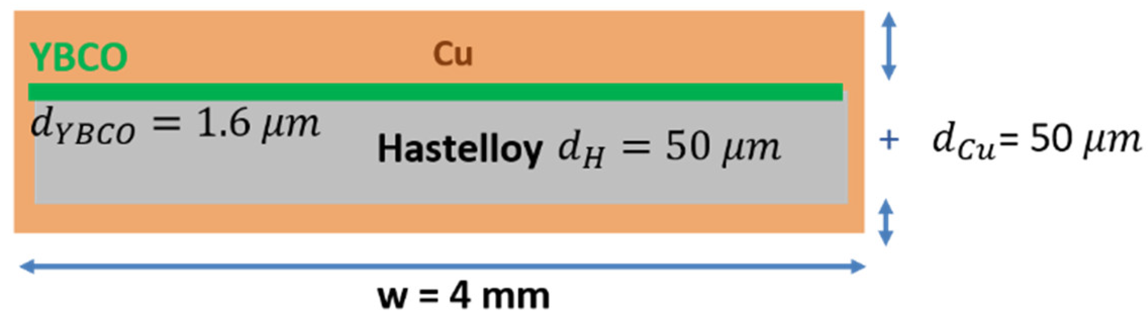
where and are thicknesses of the copper and superconductor layer, respectively. Substrate resistivity can be ignored here, since the resistivity of the copper stabilizer is significantly less than that of the substrate (Hastelloy or stainless). The temperature-dependent resistivity of the stabilizer that includes contributions from Cu layers and the substrate is:
where and are temperature-dependent resistivities of the Cu layer and the substrate, and and are their respective thicknesses. For the net heat capacity, ignoring the thin ReBCO layer, we obtain:
where and are temperature-dependent heat capacities of the Cu layer and the substrate. Since current sharing between the superconductor and stabilizer layers is sustained across a significant portion of the temperature range, no current sharing temperature can be defined in the case of HTS, and we assume that the current flows in parallel in the superconductor and the stabilizer, leading to an equal voltage drop across both layers. This simple approach ignores interlayer resistance and the possible inequality of the superconductor and stabilizer potential due to a difference in the current sharing length [24]. The net resistivity of the tape conductor is then:
where
For the temperature dependence of the critical current and n-value , we use polynomial fits to the experimental data of [22]. The equation for the can then be solved numerically for any given , ) using the Newton–Raphson method. For the temperature dependence of the heat capacity of the copper stabilizer , and also the heat capacity and resistivity of the substrate (assuming it to be SS304 stainless steel), the interpolated values were used. For the stabilizer layer, we assumed residual resistance ratio , ignored the magneto-resistance contribution and used known analytic dependence [25] to calculate the temperature-dependent resistivity. Based on the manufacturer’s specifications, the following conductor parameters were assumed: tape width: , ReBCO layer thickness: , copper stabilizer layer thickness dCu = 50 µm, substrate thickness , 4.2 K, 15 T) = 1900 A, and .
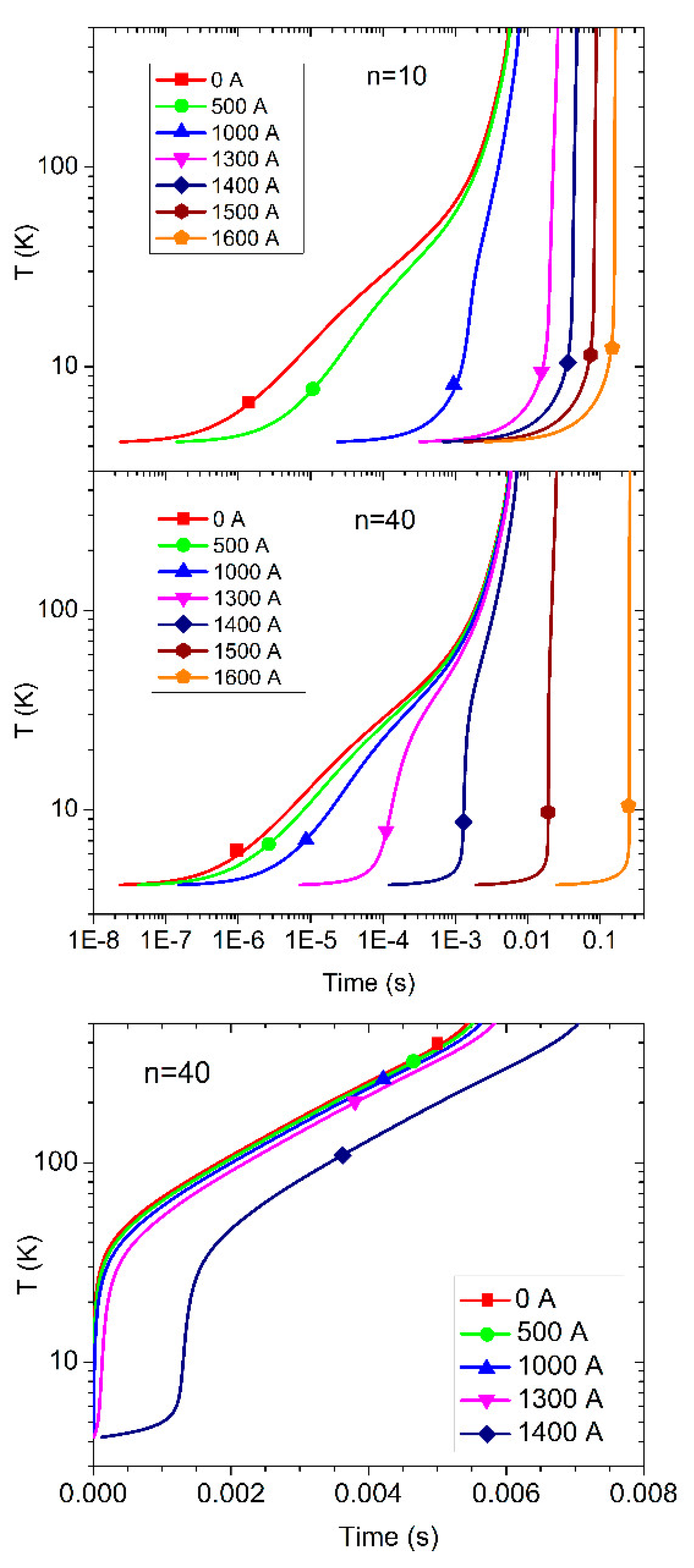
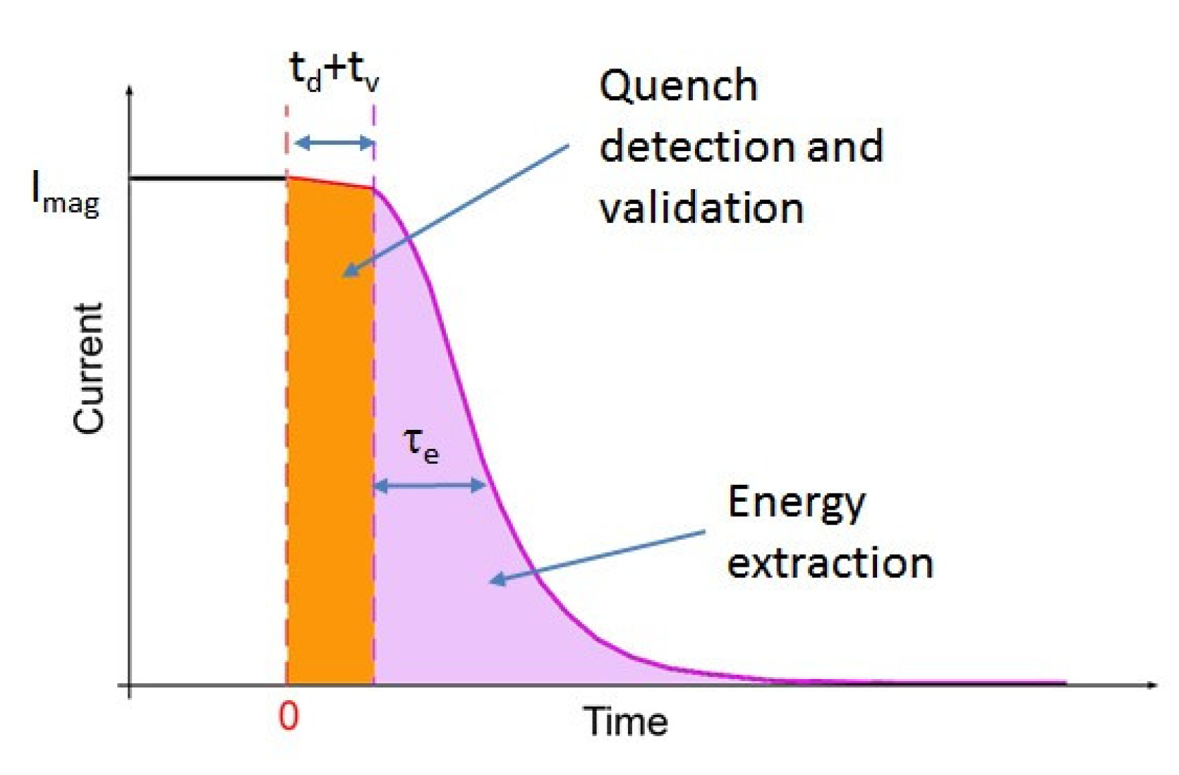
In Figure 2, results for the hot spot temperature evolution as a function of time are shown for the value of the operational current of 1500 A (), and various levels of degradation, starting from (which would be the case equivalent to a crack formation across the entire width of the superconducting layer) to its nominal value. Remarkably, it would only take 5.5 ms for the hot spot to reach 500 K in the case of . It is notable that in the case of only partial degradation, the temperature initially rises very slowly; it stays elevated above the background for just a few degrees Kelvin, followed by a quick thermal runaway that is nearly as quick as in the case of . As evidenced by the plots in Figure 2, a lower n-value is associated with the extension of this regime in the temporal and temperature scales. Such behavior is consistent with a formation of a flux-flow zone within the conductor that can persist over longer times or become “stagnated” if conditions are not purely adiabatic and heat is constantly removed from the conductor. It is also in contrast to that of LTS conductors, where the voltage rise is typically associated with a formation of the normal zone that either shrinks or expands rapidly, without exhibiting an intermediary stable configuration for the hot spot. While voltage developed in the “slow” regime can be very low, the advantage of its persistence may be taken, and multiple voltage measurements can be averaged together to improve sensitivity of the quench detection [26]. In order to estimate the voltage developing across the hot spot, normal zone propagation velocity (NZPV) should be considered. Measurements of NZPV in ReBCO conductors have been reported by several groups. In [27], NZPV was measured for the YBCO coated conductor in a self-field at 80 K, at the condition of minimum energy required to initiate the propagation. The dependence of NZPV upon in this case is nearly linear, having NZPV ≈ 7.5 mm/s at 95% of the critical current. In [28], NZPV of the coated conductor was measured at 4.2 K in a self-field, yielding ≈ 4 mm/s at 56% of . At a lower temperature and high field conditions of 14 T relevant to high-field magnet applications, detailed measurements of NZPV were reported in [29], where = 1 NZPV was found to be in the range of 20–400 mm/s for the corresponding temperature range of 27–43 K. For the intermediate temperature of 40 K and more practical value of ~0.7, the measured NZPV was ~20 mm/s. In LTS conductor windings, resistance develops mainly due to quench propagation: the normal zone grows in size both along the conductor and, transversely, across the winding turns, as sketched in Figure 3. In contrast, in the HTS conductor coil windings resistance develops mainly due to heating of a localized hot spot. When using the 20 mm/s value for NZPV as discussed above, one could expect in our simulated case the normal zone to expand no more than ~0.11 mm linearly along the conductor over the time interval of the thermal runaway in the case of = 0. By combining this number with the conductor resistivity at 500 K, one would obtain ∼ 24 mV of voltage drop across the normal zone heated to 500 K. Our estimate clearly highlights challenges to the voltage-based detection of HTS-based high-field accelerator magnets. Firstly, voltage detection threshold of 24 mV is at the low end of what is presently used for large LTS accelerator magnets; having a lower threshold is often impossible, due to significant electromagnetic background noise present during the operation of such magnets and power electronics that are connected to it. However, the most important factor is the time needed for quench validation and energy extraction, which cannot be reduced to match this conductor-defined time margin, as the former is ultimately limited by the magnet size and its stored energy. A typical timeline for magnet energy extraction is shown in Figure 4, where detection time depends upon the sensitivity and thresholds of the quench detection system, and “validation time” is defined by the hardware. Typically, for LTS accelerator magnets, () = 7 − 15 ms. Stored energy is normally converted into heat dissipated over winding resistance and any additional “dump” resistor added to the magnet circuit. Characteristic extraction time depends upon the magnet winding inductance and the sum of the winding resistance and the dump resistance, and magnet current decay can be written as follows:
As magnet inductance L scales with the magnet size, can be reduced either by increasing Rmag(t) by some active means, such as the use of protection heaters [30] or induced coupling losses [31], or by increasing Rdump. Realization of active protection for HTS is difficult due to the large enthalpy margin. Increasing the dump resistor value proportionally increases the voltage developing across the magnet during the extraction, and the latter is limited by the insulation breakdown limits and onset of gas discharge in the cryogenic environment. Also, cabling of HTS conductors is a common way of reducing magnet inductance while increasing its operational current.
A typical extraction time of large LTS magnets is 100s of milliseconds. Thus, it is clear that the quick thermal runaway of a “standard” ReBCO conductor appears to be a major factor limiting the protection margins of large HTS magnets. Various approaches undertaken to overcome this problem can be separated into three major categories: the development of new and more sensitive detection techniques, conductor modification and the development of new protection methods. In the rest of the paper, we will mainly focus on the quench detection topic, while briefly reviewing relevant activities on conductor modification and protection.
3. Non-Voltage Quench Detection Techniques
In this section, the most prominent non-voltage techniques aimed at the detection of a normal zone development in HTS conductors are discussed. They are summarized in Table 1 below:
3.1. Magnetic Techniques
A well-known technique used for low-temperature superconductor magnets is based upon sensing the temporal variation of the magnetic field in the vicinity of a developing quench. Firstly, the initial hot spot is unlikely to be distributed symmetrically with respect to the conductor cross-section. This is because at the origin of such a zone, a local material defect of the HTS conductor could be present, or the magnetic field in that location could be higher compared to the rest of the conductor. Once a resistive zone appears, the current flow redistributes outwards from this zone, becoming asymmetric with respect to the conductor central axis. If the HTS conductor is a multi-strand cable (of Rutherford [14,32], Roebel [33,34], CORC® [35,36], twisted stack [37] or other type), then the redistribution is generally also a function of inter-strand resistance, and a complex current flow pattern may form as a result. It should be noted that in the case of good current sharing (i.e., very low inter-strand resistance), current inhomogeneity is expected to be most apparent at a very early onset of the flux-flow regime. In addition, for Rutherford and CORC®-type cables, the current follows a “solenoidal” path along the cable strands in the superconducting state, but flows straight through the normal zone. Therefore, the solenoidal current path is effectively “interrupted” at the normal zone location. This is discussed in more detail in [38]. The described transient current redistribution can be detected by a properly positioned array of magnetic sensors.
One known technique [39,40] uses an array of inductive pickup coils, usually called a “quench antenna”. A comprehensive analysis of quench antenna signals expected from a developing quench was performed in [41]. Quench antennas have been used quite successfully for identifying quenches in various LTS high-field magnets. Analyses of current redistribution at the inter-strand level of the Rutherford cable during quench propagation have been studied in [42,43], both demonstrating that improving inter-strand conductivity increases quench propagation velocity, and providing a modeling background for calculating magnetic transients due to such redistribution. For HTS conductors, however, the use of quench antennas so far has been limited. Slow quench propagation implies lower local dB/dt and proportionally lower signals generated by an inductive-type quench antenna.
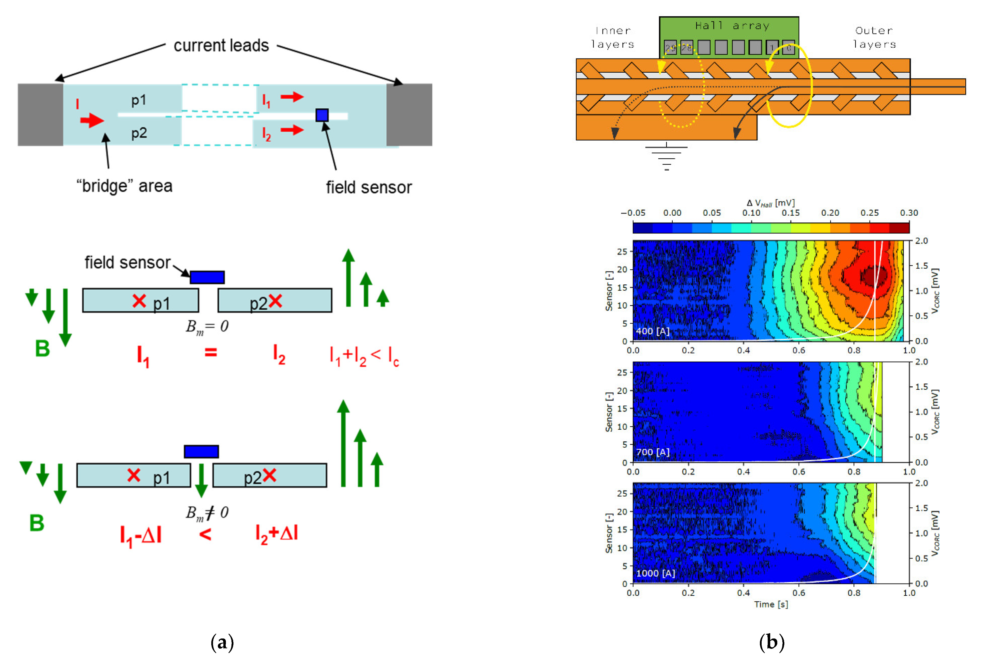
At the same time, the efficiency of the magnetic method for quench detection was shown in [44], where a miniature Hall sensor was used to detect current distribution imbalances occurring in the space between current-carrying ReBCO conductors. In the superconducting state, all HTS tapes comprising the cable carry are approximately the same current, and therefore the normal field component at the sensor location is fully compensated, due to the corresponding components of the two currents in neighboring tapes being equal in magnitude and opposite in direction. As the critical current of one tape is reduced because of a local hot spot, the excess current flows into the other tape. Such redistribution produces an unbalanced out-of-plane magnetic field in the gap region, as sketched in Figure 5a. Such a field is readily detectable with an appropriate Hall sensor placed at a convenient point at the middle line between the two tapes; for instance, near one of the current terminals. The key advantage of monitoring the redistribution of the current instead of the appearance of the resistive voltage is that the sensitivity of the former method is much higher, being defined by the ratio of the currents flowing in the quenching and non-quenching conductor strands, while the voltage technique relies on measuring the absolute value of the dissipation. The magnetic technique, in principle, allows measuring even minute resistance in the superconducting path, down to thermally activated flux creep levels corresponding to electric fields of 10−10 V/cm or lower. In practice, current redistribution between parallel conducting paths occurs at whatever minute manifestation of resistance in either part, and precedes the appearance of a practically detectable voltage. The intrinsic difficulty of using this method for monitoring a large accelerator magnet comes from the fact that the conductor in the winding needs to be split along the length into at least two currents carrying sub-elements that are joined at the terminals but exhibit no mutual current sharing along the winding. Besides, the stray field of the magnet may interfere with the Hall sensor measurement of current redistribution, although this effect can be mitigated by performing differential measurements with an array of Hall sensors installed at various locations near coil terminals. Recently, the technique has been applied successfully to detect early onset of quenching in a ReBCO-based CORC® cable [45], where multiple tapes are wound together around a solid copper former. The termination of the CORC® cables is made in such a way that individual tapes are soldered to the common tubular terminal at different axial locations along that terminal in order to distribute current uniformly. If a Hall sensor array is placed along this distributed terminal, the quenching onset can be readily detected by observing the current density (and thus a corresponding magnetic field distribution) shifting away from the tape that is being quenched (See Figure 5b). It should be noted that the, technique works on a single CORC® conductor only because current sharing between tapes is typically rather poor and most of the redistribution occurs within the terminals. However, in a case where several individual CORC® conductors are used to form a cable (cable-in-conduit geometry), the approach is expected to be efficient for any practical length. This has been recently demonstrated experimentally [46]. Further experiments aimed at justifying this approach for long lengths of HTS cable are currently in progress.
3.2. Optical Techniques
A variety of techniques using optical fibers have been proposed for HTS quench detections. All of them rely on detecting a change in the optical properties of the fiber, due to either a local thermal expansion (hence temperature sensing) or thermally induced variation of strain. Discreet sensors based on fiber Bragg gratings (FBGs) [47,48,49,50] have been found to perform well at cryogenic temperatures and detect variations of temperature and strain. Gratings are integrated along the length of the fiber path and interrogated optically in order to measure thermally induced local variations of their period. A thermal sensitivity of ~1 K at around 20 K base temperature has recently been reported [50]. FBG sensors have been successfully integrated into large accelerator magnets for monitoring strain [47], and the use of FBGs appears promising for quench detection in fusion magnet cables [51]. A clear drawback of using FBGs for quench detection, however, is that their discrete nature does not couple well with the low NZPV of the HTS conductor.
Continuous fiberoptic sensors based on Rayleigh scattering [52,53,54] are an attractive alternative to their discreet counterparts, as they allow for both a distributed measurement of temperature along the entire length of superconducting coil winding and for the precise localization of the developing hot spots. For this technique, thermal sensitivity scales inversely with the probed length of the optical fiber, and thermal sensitivities greater than 7 K/cm [52], as well as a minimally detectable size of the normal zone of less than 5 mm [53], have been reported. It should be noted, however, that distributed optical sensing requires substantial computational power to achieve real-time quench detection in long lengths of HTS conductor.
Other optical methods for continuous thermal sensing are being explored; for example, the use of Raman scattering [55] and Brillouin scattering [56,57,58] seems promising. Optical techniques would typically suffer from insufficient thermal sensitivity at lower temperatures, due to reduction of the coefficient of thermal contraction for nearly all materials when approaching absolute zero, and, practically, at temperatures below 15–20 K. While most of the optical quench detection experiments were conducted at 77 K, it is technically possible to extend the sensitivity range down to lower temperatures using specially designed optical fibers. Improving the sensitivity of FBG and Rayleigh sensors at low temperatures may be achieved by utilizing various special coatings for the sensing fiber that have a larger thermal expansion coefficient than the original fiber material [59] in the low temperature range.
3.3. Acoustic Techniques
Whenever a mechanical disturbance occurs in a superconducting magnet, it results in a burst of acoustic emission (AE). Sources of acoustic emission in superconducting magnets are well summarized in [60,61,62]. Passive listening to magnet AE and analysis of the acoustic data in terms of arrival delays, frequency content and amplitude have been successfully used to diagnose low-temperature superconducting magnets in the past [63,64,65,66], and this field is continuing to stay in active development. In application to the HTS magnets, however, the use of passive acoustic diagnostics so far has been limited. As discussed earlier, mechanical disturbances are not expected to cause quenching in HTS magnets, and AE caused by those disturbances may be not particularly relevant for diagnostic purposes. At the same time, hot spot development results in a number of secondary acoustic effects, such as micro-mechanical motion along various interfaces due to thermal expansion, dislocation motion and cryogenic liquid boiling. Onset of AE due to these sources has indeed been reported for HTS conductors [67,68,69,70,71,72], but only for cases where a significant overcurrent was supplied to the conductor and heating was quite substantial (such as in a superconducting fault current limiter [73]). It remains unclear at the moment if passive AE sensing can be reliably used for the detection of hot spots where local temperature variations are of the order of 1 K or less, which would be practical for quench detection. It is possible that new developments in cryogenic electronics will enable such technology in the future. Even so, given that AE may be also produced by purely mechanical means unrelated to quenching, passive AE monitoring has not yet been developed into a viable quench diagnostic technique for HTS coils. In addition, speaking of quench detection specifically, AE monitoring cannot fulfill such a role even for LTS coils because the conductor transitioning into a normal state upon reaching its (B, T) margin is not expected to emit acoustic waves at all.
It appears more practical to track changes in the coil or the conductor that are caused by the localized heating. Unlike AE bursts, those changes are expected to develop gradually with temperate rise, and once detected, can be treated as a reliable indicator of heating in a fashion similar to the resistive voltage. In order to accomplish this, active acoustic techniques are being developed that employ externally generated acoustic waves for probing changes in the coil. Attempts were made in the past to monitor the acoustic transfer function of the magnet coil and accomplish hot spot detection based on variations of that function [74,75,76]. As it is a priori unknown in what frequency range transfer function variation may be expected, such a method does not seem to be very practical. At the same time, acoustic thermometry is presently well-established in application to liquids and gaseous bodies, where thermally induced variations of the sound velocity can be readily measured. It is usually accomplished by generating an acoustic pulse and measuring its time of travel across the body. Piezoelectric transducers can be used for transmitting and receiving such pulses, having either two transducers—a transmitter and a receiver placed at the opposite sides of the body—or a single transducer operating in a pulse-echo mode [77]. However, this simple approach is difficult to implement for an arbitrary-shaped solid object due to a much smaller magnitude of variation, as well as multiple reflections and mode conversions taking place inside the object; for example, in a quasi-one-dimensional solid rod where the transverse sound velocity is given by , and its temperature dependence is dominated by that of the Young’s modulus E(T) rather than a much smaller density variation ρ(T). The former can be approximated as [78]:
where is the Young’s modulus at zero Kelvin temperature, and s and τ are adjustable parameters. For common metals and alloys at liquid nitrogen temperature (77 K), the relative change is then just 10–100 ppm, yielding a sound velocity change per degree that is 2–3 orders of magnitude less than liquids or gases. Another significant complication is that a large variety of wave modes exist in solids, including compression, shear, twist and Lamb surface waves. These wave modes exhibit different group velocities [79] and can evolve from one mode to another along the body surfaces and interfaces. This complication, however, can be turned into an advantage if a multiply scattered wave is used to conduct the measurement. A principle of this method and its realization in practice are shown in Figure 6. When a short (~1 µs) acoustic pulse is emitted into the coil under test with a piezoelectric transducer, the signal received by another transducer at the opposite coil end will exhibit multiple oscillations and typically extend along the time axis for several milliseconds. Such an extended wave packet is called “coda” and is a result of multiple scattering, mode conversions and interference of secondary waves on their path to the receiver. An advantageous property of a coda wave is that it would “sample” the coil winding multiple times before reaching the receiver. Therefore, every time the wave passes through a thermally disturbed region, it acquires a small additional delay, leading to the accumulation of the phase shift of the received signal relative to the reference coda acquired prior to the occurrence of thermal disturbance. For the first time, the nature of coda waves was discussed in [80] in connection to geophysics, and their ability to diagnose minute thermal changes in the medium was noted in [81]. In order to quantify thermally induced local variations of sound velocity in practice, an excitation pulse is applied to the coil at t0, and a fixed portion of the transient waveform of a duration tw is acquired, starting at t0 + ∆t. The first acquired waveform ) is stored as a reference, and then cross-correlated with every subsequently acquired waveform fi(t) to find:
The relative time shift is then calculated, corresponding to the absolute maximum of each in the interval, such as that ; . Thermal sensitivity is expected to be proportional to [81], and thus one can benefit from the large mechanical Q-factor of the coil by increasing ∆t further into the “tail” of the coda. Some recent examples of applying this technique for detecting hot spots in HTS conductors are experiments on a HTS tape stack [82], as well as a single ReBCO tape and coils wound with CORC® cable [83]. A similar waveform monitoring approach was proposed in [84] for the thermal mapping of biological tissues with medical ultrasound. Acoustic thermometry has an important advantage of being non-invasive, as both receiving and transmitting transducers can be placed along the outer surfaces of the magnet. It is also largely insensitive to electromagnetic and mechanical noise in the system, in contrast to the passive acoustic quench detection. A known complication may be to ensure that the acoustic energy applied to the coil is sufficiently high in order to achieve good sensitivity while letting the coda sample the coil winding without cross-cutting through some non- essential structural coil elements. In the latter case, sensitivity to localized hot spots in the windings will be reduced. As an alternative to sending the wave directly into the coil under test, acoustic waveguides [85,86,87] can be potentially explored to carry acoustic waves along the windings and detect hot spots in a manner similar to a fiber optic technique, but using acoustic pulses instead of optical ones. Several advantages over optical techniques can be anticipated, such as a much more robust and less expensive sensor and acquisition hardware, as well as an ability to separate stress and thermal responses using frequency-based methods [88].
3.4. Capacitive Technique
Change in capacitance can be employed for quench detection quite successfully for HTS coils directly immersed into a cryogenic fluid (liquid helium or nitrogen) [89,90]. With this method, capacitance is monitored between two structural elements of an HTS coil separated by an insulation layer that is partially or fully impregnated with the cryogenic liquid. Electrical permittivity of helium and nitrogen decreases only slightly with temperature while in a liquid phase, but varies sharply upon a phase change to the gaseous state [91,92]. When locally generated heat at a hot spot partially or fully evaporates the impregnating cryogenic liquid enclosed between monitored structural parts, a corresponding variation of electrical capacitance is observed. The low heat of evaporation in combination with a narrow gap between structural parts may drive significant variations of capacitance for very low heat deposition. In liquid helium tests, heat deposition as low as 0.3 J has been readily observed, and upon approaching a thermal runaway, the capacitance variation becomes an extremely sensitive indicator of dissipation, capable of detecting heat at levels that are hard to measure with the traditional voltage-based detection or other non-voltage methods.
3.5. RF-Based Techniques
A technique probing radio-frequency impedance change caused by quenching has been reported in [93]. The method may be of interest in a situation where large mechanical or low-frequency electromagnetic noise is present, and therefore the use of magnetic or acoustic techniques is less preferable. Another radio-frequency-based technique of time–frequency domain reflectometry (TFDR) [94,95,96] has been applied successfully to monitor the long length of the HTS cable and detect hot spots based on local variations of impedance. While no TFDR experiments have been conducted on practical HTS coils to date, the method seems promising as a sensitive and minimally invasive tool for hot spot detection and localization.
4. Conductor Modification
Modifying conductor geometry is one possible way of improving protection margins of HTS-based superconducting accelerator magnets. One obvious step that may be undertaken is to increase the thickness of the metal stabilizer in order to be able to reduce the rate of heating at the developing hot spot. The effectiveness of this approach is demonstrated, for example, in [97], where the increase of the copper stabilizer cross-section in the ReBCO conductor from 0.16 mm2 to 0.4 mm2 yielded a two times reduction of the hot spot temperature in the current dump experiment on an HTS insert coil. An obvious drawback of this approach, however, is that the proportionally reduced engineering current density of the conductor reduces the magnet performance. Instead of increasing the stabilizer thickness, a different metal with a high residual resistivity ratio (RRR) may be used to achieve the same goal. In [98], an aluminum stabilizer was electroplated on the ReBCO conductor; high-purity Al can reach RRR > 1000 and 3 mm of 99.999% Al is equivalent by resistivity to 40 mm of electroplated Cu at T < 20 K.
Another viable approach is improving the heat transfer away from the hot spot by coating the conductor with a material with high thermal diffusivity, as discussed in [99]. The advantage of this approach is a somewhat improved (several times) NZPV and the possibility to induce an inter-layer quench propagation within the acceptable time margin. The observed improvement is, however, somewhat limited, and may still be insufficient to enable the use of conventional voltage-based quench detection schemes. An interesting approach to increasing the NZPV in coated conductors by means of increasing interfacial resistance between the superconductor and stabilizer was proposed in [100] and further developed in [101]. Effects of the interfacial resistance on the current transfer between the superconductor and the stabilizer layer were studied in detail by Levin et al. [24], who showed that the current diffusion length , where is the interfacial resistance and and are stabilizer thickness and normal state resistivity, respectively; where it replaces the thermal diffusion length in the heat transfer equation, leading to a faster quench propagation. This approach allows achieving NZPVs that are comparable to those of LTS conductors, thus making known conventional quench detection schemes applicable. On the other hand, this approach reduces the HTS conductor stability margin. While this is not generally a problem for a very homogeneous HTS conductor, it may become a problem for a conductor with distributed local defects that will become more prone to quenching at a lower level of thermal disturbances.
In multi-tape HTS cables with current sharing between tapes, an important factor in improving stability and reducing hot spot temperatures is current sharing between neighboring HTS conductors comprising a multi-tape cable or a coil with no electrical insulation between turns. The non-insulated (NI) coils have been investigated since the early work of Hahn [102], where a non-insulated ReBCO coil was shown to carry 2.7 without burning. Recently, NI coils have become a topic of intense research [103,104,105] due to a phenomenal stability to quenching observed in those coils. This stability comes with the price of an inability to vary the current in coils at a fast rate, since any excess current would flow radially between the turns rather than along the conductor length. An interesting solution to overcome this limitation was proposed and explored in [106,107], where a layer of a special material exhibiting a thermally driven metal-insulator transition material is deposited on the tape. It serves as an inter-tape insulation at a low temperature and becomes highly conductive at an elevated temperature, thus promoting current sharing between neighboring turns of the coil.
5. Magnet Protection against Damage Caused by Quench
5.1. Protection Heaters
In the LTS accelerator magnet, active protection methods using external heaters [30] are commonly used to quickly increase the size of the normal zone upon detecting a quench, and to redistribute the dissipation of the magnet’s stored energy over a large volume, thus preventing a localized burnout. Typically, protection heaters would have a number of “heating stations”, where more heat is released per unit area and where quenching will be initiated (although continuous heating strips are also being used in shorter magnets). The normal zone, once formed, would then expand between these heating stations and further increase the coil resistance. In HTS magnets, such an approach may prove difficult to realize, due to a large enthalpy margin requiring a large amount of heat to be deposited by the heater in order to initiate quenching. Then, since the propagation velocity is very low, heating stations should be placed either very close to each other or should form a continuous heating strip along the entire length of HTS coil winding. Regardless, protecting the HTS magnet with high-power heaters was shown to be a viable protection option for high-field HTS solenoids [108]. Protection heater delay times have been evaluated in [109], indicating some viability of also using this protection method for HTS magnets. It was found, however, that the heater delay increases with the quench margin, and the use of heaters at low (<15 T) fields may be increasingly problematic.
5.2. Coupling and AC Loss
Another, more recently developed method of active protection is coupling-loss-induced quenching (CLIQ) [110], which relies on generating heat in the bulk of the cable conductor. It is performed by discharging a capacitor into the coil by means of a thyristor switch, which generates an oscillatory current and associated coupling losses between the conductor strands. While the method has demonstrated its high effectiveness for protecting large-scale LTS accelerator magnets [31,111,112,113], its application to HTS magnets has so far been very limited. Nevertheless, estimates can be made with respect to the viability of using AC loss-based protection in general for HTS coils. For example, based on the reported AC loss data for coated ReBCO conductors in high fields [114], measured quench energy at similar conditions [115] and assuming the protection device generates oscillations at ~100 Hz frequency, AC loss heating is expected to be approximately 1 W/m, or ~2.5 W/cm3 when recalculated for the tape conductor dimensions, which is in the same range as typical minimal quench energy (MQE). An interesting proposition was made in [116], where a conductor was split into two equal halves in a similar fashion as is performed for the Hall sensor-based quench detection in [44], but the geometry is being explored for protection against quench damage. Upon detecting a quench, a current pulse (in excess of ) is applied to central taps at parallel branches of the split conductor. As inductance in this case is nearly canceled out along the conductor path, the method can be applied to long windings and realized in various configurations, such as, for example, a ReBCO ROEBEL cable with half of its strands electrically insulated from another half, or two electrically insulated tape stacks or a pair of insulated and twisted multi-filamentary Bi-2212 wires. Compensated inductance also enables the use of high-frequency currents for coil protection, which can drastically improve heat deposition and potentially enable novel protection mechanisms presently incompatible with long magnets due to their higher inductive impedance.
6. Summary
Quench detection and protection of HTS high-field magnets for future accelerators is a standing problem that requires a multi-faceted solution. That solution will likely be based on a combination of voltage and non-voltage-based approaches realized simultaneously, to provide a necessary redundancy and sensitivity of the detection. For the non-voltage methods, recent research efforts by various groups have already offered several promising new approaches. Furthermore, quench detection and protection capabilities can be further improved by conductor modifications aiming at faster quench propagation, and by the realization of novel protection approaches, such as those based on AC losses. Emerging applications of HTS materials in high-energy physics and fusion energy science will be driving these developments for the foreseeable future.
Funding
This work was supported by the U.S. Department of Energy, Office of Science, Office of High Energy Physics, under contract #DE-AC02-05CH11231.
Acknowledgments
M.M. is thankful to E. Ravaioli, E. Hershkovitz, D. Arbelaez, R. Teyber, X. Wang, S. Prestemon and S. Gourlay for fruitful collaborations and discussions on various magnet diagnostics and instrumentation topics reviewed in this article. Additionally, numerous discussions with members of the Diagnostics and Instrumentation Working Group of the US Magnet Development Program are gratefully acknowledged.
Conflicts of Interest
The funders had no role in the design of the study; in the collection, analyses or interpretation of data; in the writing of the manuscript, or in the decision to publish the results.
References
- Bednorz, J.G.; Müller, K.A. Possible high Tc superconductivity in the Ba-La-Cu-O system. Z. Phys. B Condens. Matter 1986, 64, 189–193. [Google Scholar] [CrossRef]
- Breschi, M.; Cavallucci, L.; Ribani, P.L.; Gavrilin, A.V.; Weijers, H.W. Analysis of quench in the NHMFL REBCO prototype coils for the 32 T Magnet Project. Supercond. Sci. Technol. 2016, 29, 055002. [Google Scholar] [CrossRef]
- Bai, H.; Abraimov, D.V.; Boebinger, G.S.; Bird, M.D.; Cooley, L.D.; Dixon, I.R.; Kim, K.L.; Larbalestier, D.C.; Marshall, W.S.; Trociewitz, U.P.; et al. The 40 T superconducting magnet project at the national high magnetic field laboratory. IEEE Trans. Appl. Supercond. 2020, 30, 1–5. [Google Scholar] [CrossRef]
- Larbalestier, D.C.; Jiang, J.; Trociewitz, U.P.; Kametani, F.; Scheuerlein, C.; Dalban-Canassy, M.; Matras, M.; Chen, P.; Craig, N.C.; Lee, P.J.; et al. Isotropic round-wire multifilament cuprate superconductor for generation of magnetic fields above 30 T. Nat. Mater. 2014, 13, 375–381. [Google Scholar] [CrossRef] [PubMed]
- Gupta, R.; Anerella, M.; Joshi, P.; Higgins, J.; Lalitha, S.; Sampson, W.; Schmalzle, J.; Wanderer, P. Design, construction, and testing of a large-aperture high-field HTS SMES coil. IEEE Trans. Appl. Supercond. 2016, 26, 1–8. [Google Scholar] [CrossRef]
- Fleishman, L.S.; Volkov, E.P.; Malginov, V.A.; Malginov, A.V.; Kuntsevich, A.Y.; Sheynshteyn, A.S. Fault current limitation by a transformer type FCL based on the second generation HTS wires. IEEE Trans. Appl. Supercond. 2011, 21, 1263–1266. [Google Scholar] [CrossRef]
- Colangelo, D.; Dutoit, B. MV power grids integration of a resistive fault current limiter based on HTS-CCs. IEEE Trans. Appl. Supercond. 2013, 23, 5600804. [Google Scholar] [CrossRef] [Green Version]
- So, J.; Lee, S.; Kim, W.-S.; Lee, J.-K.; Choi, K. Design of an HTS fault current limiting module for an MVDC power grid. IEEE Trans. Appl. Supercond. 2020, 30, 1–5. [Google Scholar] [CrossRef]
- Jin, J.X.; Islam, M.R.; Khan, A.G. Development of HTS cable-based transmission systems for renewables. In Renewable Energy and the Environment; Springer: Singapore, 2018; pp. 71–114. ISBN 9789811072864. [Google Scholar]
- Sytnikov, V.; Kashcheev, A.; Dubinin, M.; Karpov, V.; Ryabin, T. Test results of the full-scale HTS transmission cable line (2.4 km) for the st. Petersburg project. IEEE Trans. Appl. Supercond. 2021, 31, 540805. [Google Scholar] [CrossRef]
- Rossi, L.; Senatore, C. HTS accelerator magnet and conductor development in Europe. Instruments 2021, 5, 8. [Google Scholar] [CrossRef]
- Wang, X.; Gourlay, S.A.; Prestemon, S.O. Dipole magnets above 20 Tesla: Research needs for a path via high-temperature superconducting REBCO conductors. Instruments 2019, 3, 62. [Google Scholar] [CrossRef] [Green Version]
- Piekarz, H.; Hays, S.; Blowers, J.; Claypool, B.; Shiltsev, V. Record fast-cycling accelerator magnet based on HTS conductor. Nucl. Instrum. Methods Phys. Res. A 2019, 943, 162490. [Google Scholar] [CrossRef]
- Zlobin, A.V.; Novitski, I.; Barzi, E. Conceptual design of a HTS dipole insert based on Bi2212 Rutherford cable. Instruments 2020, 4, 29. [Google Scholar] [CrossRef]
- Todesco, E.; Bottura, L.; De Rijk, G.; Rossi, L. Dipoles for high-energy LHC. IEEE Trans. Appl. Supercond. 2014, 24, 1–6. [Google Scholar] [CrossRef] [Green Version]
- Huang, T.; Martinez, E.; Friend, C.; Yang, Y. Quench characteristics of HTS conductors at low temperatures. IEEE Trans. Appl. Supercond. 2008, 18, 1317–1320. [Google Scholar] [CrossRef]
- Haro, E.; Stenvall, A.; van Nugteren, J.; Kirby, G. Modeling of minimum energy required to quench an HTS magnet with a strip heater. IEEE Trans. Appl. Supercond. 2015, 25, 1–5. [Google Scholar] [CrossRef] [Green Version]
- Wang, X.; Caruso, A.R.; Breschi, M.; Zhang, G.; Trociewitz, U.P.; Weijers, H.W.; Schwartz, J. Normal zone initiation and propagation in Y-Ba-Cu-O coated conductors with Cu stabilizer. IEEE Trans. Appl. Supercond. 2005, 15, 2586–2589. [Google Scholar] [CrossRef]
- Zhong, Z.; Ruiz, H.S.; Lai, L.; Huang, Z.; Wang, W.; Coombs, T. Experimental study of the normal zone propagation velocity in double-layer 2G-HTS wires by thermal and electrical methods. IEEE Trans. Appl. Supercond. 2015, 25, 1–5. [Google Scholar] [CrossRef] [Green Version]
- Bonura, M.; Senatore, C. Temperature and field dependence of the quench propagation velocity in industrial REBCO coated conductors. IEEE Trans. Appl. Supercond. 2017, 27, 1–5. [Google Scholar] [CrossRef]
- Chakravarty, S.; Ivlev, B.I.; Ovchinnikov, Y.N. Thermally activated flux creep in strongly layered high-temperature superconductors. Phys. Rev. B Condens. Matter 1990, 42, 2143–2148. [Google Scholar] [CrossRef] [PubMed]
- Lombardo, V.; Barzi, E.; Turrioni, D.; Zlobin, A.V. Critical Currents of YBa2Cu3O7-delta Tapes and Bi2Sr2CaCu2Ox Wires at Different Temperatures and Magnetic Fields. IEEE Trans. Appl. Supercond. 2011, 21, 3247–3250. [Google Scholar] [CrossRef]
- Wilson, M.N. Superconducting Magnets; Clarendon Press: Oxford, UK, 1983. [Google Scholar]
- Levin, G.A.; Novak, K.A.; Barnes, P.N. The effects of superconductor–stabilizer interfacial resistance on the quench of a current-carrying coated conductor. Supercond. Sci. Technol. 2010, 23, 014021. [Google Scholar] [CrossRef] [Green Version]
- Grüneisen, E. Die Abhängigkeit des elektrischen Widerstandes reiner Metalle von der Temperatur. Ann. Phys. 1933. [Google Scholar] [CrossRef]
- Shen, T.; Ye, L.; Li, P. Feasible voltage-tap based quench detection in a Ag/Bi-2212 coil enabled by fast 3D normal zone propagation. Supercond. Sci. Technol. 2016, 29, 08LT01. [Google Scholar] [CrossRef] [Green Version]
- Trillaud, F.; Palanki, H.; Trociewitz, U.P.; Thompson, S.H.; Weijers, H.W.; Schwartz, J. Normal zone propagation experiments on {HTS} composite conductors. Cryogenics 2003, 43, 271–279. [Google Scholar] [CrossRef]
- Song, H.H.; Schwartz, J. Stability and Quench Behavior of YBa2Cu3O7-x Coated Conductor at 4.2 K, Self-Field. IEEE Trans. Appl. Supercond. 2009, 19, 3735–3743. [Google Scholar] [CrossRef]
- van Nugteren, J.; Dhallé, M.; Wessel, S.; Krooshoop, E.; Nijhuis, A.; ten Kate, H. Measurement and analysis of normal zone propagation in a ReBCO coated conductor at temperatures below 50 K. Phys. Procedia 2015, 67, 945–951. [Google Scholar] [CrossRef] [Green Version]
- Ganetis, G.; Prodell, A. Results using active quench protection strip heaters on a reference design D SSC dipole magnet. IEEE Trans. Magn. 1987, 23, 499–502. [Google Scholar] [CrossRef]
- Ravaioli, E.; Datskov, V.I.; Kirby, G.; Maciejewski, M.; ten Kate, H.H.J.; Verweij, A.P. CLIQ-based quench protection of a chain of high-field superconducting magnets. IEEE Trans. Appl. Supercond. 2016, 26. [Google Scholar] [CrossRef]
- Kim, S.-C.; Ha, D.-W.; Oh, S.-S.; Song, K.-J.; Kim, S.-J.; Han, I.-Y.; Sohn, H.-S. Fabrication and properties of Bi2212 Rutherford superconducting cable. IEEE Trans. Appl. Supercond. 2009, 19, 3076–3079. [Google Scholar]
- Goldacker, W.; Grilli, F.; Pardo, E.; Kario, A.; Schlachter, S.I.; Vojenčiak, M. Roebel cables from REBCO coated conductors: A one-century-old concept for the superconductivity of the future. Supercond. Sci. Technol. 2014, 27, 093001. [Google Scholar] [CrossRef] [Green Version]
- Accelerator-Quality HTS Dipole Magnet Demonstrator Designs for the EuCARD-2 5-T 40-mm Clear Aperture Magnet. IEEE Trans. Appl. Supercond. 2015, 25, 1–5.
- Weiss, J.D.; van der Laan, D.C.; Hazelton, D.; Knoll, A.; Carota, G.; Abraimov, D.; Francis, A.; Small, M.A.; Bradford, G.; Jaroszynski, J. Introduction of the next generation of CORC® wires with engineering current density exceeding 650 A mm2 at 12 T based on SuperPower’s ReBCO tapes containing substrates of 25 μm thickness. Supercond. Sci. Technol. 2020, 33, 044001. [Google Scholar] [CrossRef]
- Wang, X.; Caspi, S.; Dietderich, D.R.; Ghiorso, W.B.; Gourlay, S.A.; Higley, H.C.; Lin, A.; Prestemon, S.O.; van der Laan, D.; Weiss, J.D. A viable dipole magnet concept with REBCO CORC® wires and further development needs for high-field magnet applications. Supercond. Sci. Technol. 2018, 31, 045007. [Google Scholar] [CrossRef] [Green Version]
- Takayasu, M.; Chiesa, L.; Minervini, J.V. Investigation of REBCO twisted stacked-tape cable conductor performance. J. Phys. Conf. Ser. 2014, 507, 022040. [Google Scholar] [CrossRef] [Green Version]
- Marchevsky, M.; Hafalia, A.R.; Cheng, D.; Prestemon, S.; Sabbi, G.; Bajas, H.; Chlachidze, G. Axial-field magnetic quench antenna for the superconducting accelerator magnets. IEEE Trans. Appl. Supercond. 2015, 25, 1–5. [Google Scholar] [CrossRef]
- Leroy, D.; Krzywinski, J.; Remondino, V.; Walckiers, L.; Wolf, R. Quench observation in LHC superconducting one meter long dipole models by field perturbation measurements. IEEE Trans. Appl. Supercond. 1993, 3, 781–784. [Google Scholar] [CrossRef] [Green Version]
- Ogitsu, T.; Devred, A.; Kim, K.; Krzywinski, J.; Radusewicz, P.; Schermer, R.I.; Kobayashi, T.; Tsuchiya, K.; Muratore, J.; Wanderer, P. Quench antenna for superconducting particle accelerator magnets. IEEE Trans. Magn. 1994, 30, 2273–2276. [Google Scholar] [CrossRef]
- Sasaki, K.; Ogitsu, T.; Ohuchi, N.; Tsuchiya, K. Study of quench propagation with quench antennas. Nucl. Instrum. Methods Phys. Res. A 1998, 416, 9–17. [Google Scholar] [CrossRef]
- Buznikov, N.A.; Pukhov, A.A.; Rakhmanov, A.L.; Vysotsky, V.S. Current redistribution between strands and quench process in a superconducting cable. Cryogenics 1996, 36, 275–281. [Google Scholar] [CrossRef]
- Jongeleen, S.; Leroy, D.; Siemko, A.; Wolf, R. Quench localization and current redistribution after quench in superconducting dipole magnets wound with Rutherford-type cables. IEEE Trans. Appl. Supercond. 1997, 7, 179–182. [Google Scholar] [CrossRef] [Green Version]
- Marchevsky, M.; Xie, Y.-Y.; Selvamanickam, V. Quench detection method for 2G HTS wire. Supercond. Sci. Technol. 2010, 23, 034016. [Google Scholar] [CrossRef]
- Teyber, R.; Marchevsky, M.; Prestemon, S.; Weiss, J.; van der Laan, D. CORC® cable terminations with integrated Hall arrays for quench detection. Supercond. Sci. Technol. 2020, 33, 095009. [Google Scholar] [CrossRef]
- Weiss, J.D.; Teyber, R.; Marchevsky, M.; van der Laan, D.C. Quench detection using Hall sensors in high-temperature superconducting CORC®-based cable-in-conduit-conductors for fusion applications. Supercond. Sci. Technol. 2020, 33, 105011. [Google Scholar] [CrossRef]
- Chiuchiolo, A.; Bajko, M.; Perez, J.C.; Bajas, H.; Guinchard, M.; Giordano, M.; Breglio, G.; Consales, M.; Cusano, A. Structural health monitoring of superconducting magnets at CERN using fiber Bragg grating sensors. In Proceedings of the EWSHM-7th European Workshop on Structural Health Monitoring, Nantes, France, 8–11 July 2014. [Google Scholar]
- Zhou, K.; Ren, L.; Shi, J.; Xu, Y.; Duan, P. Experimental Study of Fiber Bragg Grating Applied on Quench Detection of HTS Tapes. In Proceedings of the 2020 IEEE International Conference on Applied Superconductivity and Electromagnetic Devices (ASEMD), Tianjin, China, 16–18 October 2020; pp. 1–2. [Google Scholar]
- Chiuchiolo, A.; Bajas, H.; Bajko, M.; Bottura, L.; Consales, M.; Cusano, A.; Giordano, M.; Perez, J.C. Advances in Fiber Optic Sensors Technology Development for Temperature and Strain Measurements in Superconducting Magnets and Devices. IEEE Trans. Appl. Supercond. 2016, 26. [Google Scholar] [CrossRef]
- Liu, Y.; Badcock, R.A.; Fang, X.; Fang, J.; Yan, X.; Zhou, W. Selecting of FBG Coatings for Quench Detection in HTS Coils. IEEE Trans. Appl. Supercond. 2018, 28, 1–5. [Google Scholar] [CrossRef]
- Salazar, E.E.; Badcock, R.A.; Bajko, M.; Castaldo, B.; Davies, M.; Estrada, J.; Fry, V.; Gonzales, J.T.; Michael, P.C.; Segal, M.; et al. Fiber optic quench detection for large-scale HTS magnets demonstrated on VIPER cable during high-fidelity testing at the SULTAN facility. Supercond. Sci. Technol. 2021, 34, 035027. [Google Scholar] [CrossRef]
- Chan, W.K.; Flanagan, G.; Schwartz, J. Spatial and temporal resolution requirements for quench detection in (RE)Ba2Cu3Oxmagnets using Rayleigh-scattering-based fiber optic distributed sensing. Supercond. Sci. Technol. 2013, 26, 105015. [Google Scholar] [CrossRef]
- Scurti, F.; Ishmael, S.; Flanagan, G.; Schwartz, J. Quench detection for high temperature superconductor magnets: A novel technique based on Rayleigh-backscattering interrogated optical fibers. Supercond. Sci. Technol. 2016, 29, 03LT01. [Google Scholar] [CrossRef]
- Scurti, F.; Schwartz, J. Optical fiber distributed sensing for high temperature superconductor magnets. In Proceedings of the 2017 25th Optical Fiber Sensors Conference (OFS), Jeju, Korea, 24–28 April 2017; pp. 1–4. [Google Scholar]
- Jiang, J.; Wu, Z.; Liu, B.; Sheng, J.; Wang, L.; Li, Z.; Jin, Z.; Hong, Z. Thermal stability study of a solder-impregnated no-insulation HTS coil via a Raman-based distributed optical fiber sensor system. IEEE Trans. Appl. Supercond. 2019, 29, 1–4. [Google Scholar] [CrossRef]
- Zhang, X.; Lu, Y.; Wang, F.; Liang, H.; Zhang, Y. Development of fully-distributed fiber sensors based on Brillouin scattering. Photonic Sens. 2011, 1, 54–61. [Google Scholar] [CrossRef] [Green Version]
- Song, S.; Jung, A.; Oh, K. High-temperature sensitivity in stimulated Brillouin scattering of 1060 nm single-mode fibers. Sensors 2019, 19, 4731. [Google Scholar] [CrossRef] [Green Version]
- Qiu, L.; Zhu, Z.; Li, T.; Zhou, D.; Dong, Y. High-sensitivity distributed temperature sensor based on Brillouin scattering with double-coated single-mode fibers. IEEE Sens. J. 2021, 21, 6209–6216. [Google Scholar] [CrossRef]
- Lupi, C.; Felli, F.; Brotzu, A.; Caponero, M.A.; Paolozzi, A. Improving FBG sensor sensitivity at cryogenic temperature by metal coating. IEEE Sens. J. 2008, 8, 1299–1304. [Google Scholar] [CrossRef]
- Tsukamoto, O.; Sinclair, M.W.; Steinhoff, M.F.; Iwasa, Y. Origins of acoustic emission in superconducting wires. Appl. Phys. Lett. 1981, 38, 718–720. [Google Scholar] [CrossRef]
- Ige, O.O.; McInturff, A.D.; Iwasa, Y. Acoustic emission monitoring results from a fermi dipole. Cryogenics 1986, 26, 131–151. [Google Scholar] [CrossRef]
- Tsukamoto, O.; Iwasa, Y. Acoustic emission triangulation of disturbances and quenches in a superconductor and a superconducting magnet. Appl. Phys. Lett. 1982, 40, 538–540. [Google Scholar] [CrossRef]
- Tsukamoto, O.; Maguire, J.F.; Bobrov, E.S.; Iwasa, Y. Identification of quench origins in a superconductor with acoustic emission and voltage measurements. Appl. Phys. Lett. 1981, 39, 172–174. [Google Scholar] [CrossRef]
- Tsukamoto, O.; Iwasa, Y. Sources of acoustic emission in superconducting magnets. J. Appl. Phys. 1983, 54, 997–1007. [Google Scholar] [CrossRef]
- Iwasa, Y. Mechanical disturbances in superconducting magnets-a review. IEEE Trans. Magn. 1992, 28, 113–120. [Google Scholar] [CrossRef]
- Marchevsky, M.; Sabbi, G.; Bajas, H.; Gourlay, S. Acoustic emission during quench training of superconducting accelerator magnets. Cryogenics 2015, 69, 50–57. [Google Scholar] [CrossRef] [Green Version]
- Woźny, L.; Lubicki, P.; Mazurek, B. Acoustic emission from high Tc superconductors during current flow. Cryogenics 1993, 33, 825–827. [Google Scholar] [CrossRef]
- Stoev, P.I.; Papirov, I.I.; Finkel’, V.A. Acoustic emission of the HTS ceramic YBa2Cu3O7−δ in the vicinity of the superconducting transition. Low Temp. Phys. 1997, 23, 765–768. [Google Scholar] [CrossRef]
- Arai, K.; Iwasa, Y. Heating-Induced acoustic emission in an adiabatic high-temperature superconducting winding. Cryogenics 1997, 37, 473–475. [Google Scholar] [CrossRef]
- Ostrovskii, I.V.; Salivonov, I.N. Acoustic emission accompanying the superconducting transition in HTS ceramics TlBaCuO. Low Temp. Phys. 1998, 24, 50–52. [Google Scholar] [CrossRef]
- Lee, H.; Kim, H.M.; Jankowski, J.; Iwasa, Y. Detection of ‘Hot Spots’ in HTS Coils and Test Samples with Acoustic Emission Signals. IEEE Trans. Appl. Supercond. 2004, 14, 1298–1301. [Google Scholar] [CrossRef]
- Kim, K.J.; Song, J.B.; Kim, J.H.; Lee, J.H.; Kim, H.M.; Kim, W.S.; Na, J.B.; Ko, T.K.; Lee, H.G. Detection of AE signals from a HTS tape during quenching in a solid cryogen-cooling system. Phys. C 2010, 470, 1883–1886. [Google Scholar] [CrossRef]
- Kim, H.M.; Park, K.B.; Lee, B.W.; Oh, I.S.; Sim, J.W.; Hyun, O.B.; Iwasa, Y.; Lee, H.G. A stability verification technique using acoustic emission for an HTS monofilar component for a superconducting fault current limiter. Supercond. Sci. Technol. 2007, 20, 506. [Google Scholar] [CrossRef]
- Ishigohka, T.; Tsukamoto, O.; Iwasa, Y. Method to detect a temperature rise in superconducting coils with piezoelectric sensors. Appl. Phys. Lett. 1983, 43, 317–318. [Google Scholar] [CrossRef]
- Ninomiya, A.; Sakaniwa, K.; Kado, H.; Ishigohka, T.; Higo, Y. Quench detection of superconducting magnets using ultrasonic wave. IEEE Trans. Magn. 1989, 25, 1520–1523. [Google Scholar] [CrossRef]
- Ninomiya, A.; Kanda, Y.; Ishigohka, T. Monitoring of a superconducting magnet using an ultrasonic technique. Fusion Eng. Des. 1993, 20, 305–309. [Google Scholar] [CrossRef]
- Krautkramer, J. Ultrasonic Testing of Materials; Springer: New York, NY, USA, 2014; ISBN 9783662022979. [Google Scholar]
- Ledbetter, H.M. Temperature behaviour of Young’s moduli of forty engineering alloys. Cryogenics 1982, 22, 653–656. [Google Scholar] [CrossRef]
- Georgi, H. The Physics of Waves; Pearson: Upper Saddle River, NJ, USA, 1992; ISBN 9780136656210. [Google Scholar]
- Snieder, R. The theory of coda wave interferometry. Pure Appl. Geophys. 2006, 163, 455–473. [Google Scholar] [CrossRef]
- Weaver, R.L.; Lobkis, O.I. Temperature dependence of diffuse field phase. Ultrasonics 2000, 38, 491–494. [Google Scholar] [CrossRef]
- Marchevsky, M.; Gourlay, S.A. Acoustic thermometry for detecting quenches in superconducting coils and conductor stacks. Appl. Phys. Lett. 2017, 110, 012601. [Google Scholar] [CrossRef] [Green Version]
- Marchevsky, M.; Hershkovitz, E.; Wang, X.; Gourlay, S.A.; Prestemon, S. Quench Detection for High-Temperature Superconductor Conductors Using Acoustic Thermometry. IEEE Trans. Appl. Supercond. 2018, 28, 1–5. [Google Scholar] [CrossRef] [Green Version]
- Seip, R.; VanBaren, P.; Cain, C.A.; Ebbini, E.S. Noninvasive real-time multipoint temperature control for ultrasound phased array treatments. IEEE Trans. Ultrason. Ferroelectr. Freq. Control 1996, 43, 1063–1073. [Google Scholar] [CrossRef]
- Wong, T.Y.; Tang, Y.; Zou, F.; Su, Z. An ultra-high accuracy temperature measurement method using acoustic waveguide. IEEE Sens. J. 2020, 21, 1. [Google Scholar] [CrossRef]
- Wang, Y.; Zou, F.; Cegla, F.B. Acoustic waveguides: An attractive alternative for accurate and robust contact thermometry. Sens. Actuators A Phys. 2018, 270, 84–88. [Google Scholar] [CrossRef]
- Kulczyk, K.; Perks, M.P.; Smith, G.W. Ultrasonic temperature sensors, and ultrasonic waveguide connectors for use therewith. J. Acoust. Soc. Am. 1994, 95, 3682. [Google Scholar] [CrossRef]
- Lobkis, O.; Larsen, C.; Roth, R., II. Separation of applied stress and temperature effects on ultrasonic guided wave phase. AIP Conf. Proc. 2015, 211, 1650. [Google Scholar]
- Ravaioli, E.; Martchevskii, M.; Sabbi, G.; Shen, T.; Zhang, K. Quench detection utilizing stray capacitances. IEEE Trans. Appl. Supercond. 2018, 28, 1–5. [Google Scholar] [CrossRef]
- Ravaioli, E.; Davis, D.; Marchevsky, M.; Sabbi, G.L.; Shen, T.; Verweij, A.; Zhang, K. A new quench detection method for HTS magnets: Stray-capacitance change monitoring. Phys. Scr. 2020, 95, 015002. [Google Scholar] [CrossRef]
- National Aeronaut Administration (NASA). Thermophysical Properties of Helium-4 from 0.8 to 1500 K with Pressures to 2000 mpa; Createspace Independent Publishing Platform: North Charleston, SC, USA, 2018; ISBN 9781723457319. [Google Scholar]
- Jensen, J.E.; Tuttle, W.A.; Stewart, R.B.; Brechna, H.; Prodell, A.G. Brookhaven National Laboratory Selected Cryogenic Data Notebook: Sections I–IX; Brookhaven National Laboratory: Upton, NY, USA, 1980. [Google Scholar]
- Chen, B.; Hu, Y.; Li, J.; Yu, B.; Fu, P. Research on quench detection method using radio frequency wave technology. IEEE Trans. Appl. Supercond. 2020, 30, 1–5. [Google Scholar] [CrossRef]
- Lee, G.S.; Kwon, G.-Y.; Bang, S.S.; Lee, Y.H.; Chang, S.J.; Sohn, S.-H.; Park, K.; Shin, Y.-J. Time–frequency-based insulation diagnostic technique of high-temperature superconducting cable systems. IEEE Trans. Appl. Supercond. 2016, 26. [Google Scholar] [CrossRef]
- Bang, S.S.; Lee, G.S.; Kwon, G.-Y.; Lee, Y.H.; Ji, G.H.; Sohn, S.; Park, K.; Shin, Y.-J. Detection of local temperature change on HTS cables via time-frequency domain reflectometry. J. Phys. Conf. Ser. 2017, 871, 012100. [Google Scholar] [CrossRef] [Green Version]
- Lee, C.-K.; Kwon, G.-Y.; Lee, Y.H.; Lee, G.S.; Bang, S.S.; Shin, Y.-J. Insulation characteristics and fault analysis of HTS cable via stepped frequency waveform reflectometry. IEEE Trans. Appl. Supercond. 2019, 29, 1–5. [Google Scholar] [CrossRef]
- Uglietti, D.; Marinucci, C. Design of a quench protection system for a coated conductor insert coil. IEEE Trans. Appl. Supercond. 2012, 22, 4702704. [Google Scholar] [CrossRef]
- Bae, J.H.; Jeong, Y.W.; Ha, D.W. Thermal characteristics of 2G HTS tape with anodized aluminum stabilizer for cryogen-free 2G HTS magnet. IEEE Trans. Appl. Supercond. 2015, 25, 1–4. [Google Scholar] [CrossRef]
- Ishmael, S.; Luo, H.; White, M.; Hunte, F.; Liu, X.T.; Mandzy, N.; Muth, J.F.; Naderi, G.; Ye, L.; Hunt, A.T.; et al. Enhanced quench propagation in Bi2Sr2CaCu2Ox and YBa2Cu3O7-x coils via a nanoscale doped-Titania-based thermally conducting electrical insulator. IEEE Trans. Appl. Supercond. 2013, 23, 7201311. [Google Scholar] [CrossRef]
- Lacroix, C.; Fournier-Lupien, J.-H.; McMeekin, K.; Sirois, F. Normal zone propagation velocity in 2G HTS coated conductor with high interfacial resistance. IEEE Trans. Appl. Supercond. 2013, 23, 4701605. [Google Scholar] [CrossRef]
- Giguere, J.; Lacroix, C.; Dupuis-Desloges, F.; Fournier Lupien, J.-H.; Sirois, F. High normal zone propagation velocity in copper-stabilized 2G HTS coated conductors. Supercond. Sci. Technol. 2021. [Google Scholar] [CrossRef]
- Hahn, S.; Park, D.K.; Bascunan, J.; Iwasa, Y. HTS pancake coils without turn-to-turn insulation. IEEE Trans. Appl. Supercond. 2011, 21, 1592–1595. [Google Scholar] [CrossRef]
- Kim, S.B.; Saitou, A.; Joo, J.H.; Kadota, T. The normal-zone propagation properties of the non-insulated HTS coil in cryocooled operation. Phys. C Supercond. 2011, 471, 1428–1431. [Google Scholar] [CrossRef]
- Uglietti, D.; Wesche, R.; Bruzzone, P. Construction and test of a non-insulated insert coil using coated conductor tape. J. Phys. Conf. Ser. 2014, 507, 032052. [Google Scholar] [CrossRef] [Green Version]
- Hasegawa, S.; Ito, S.; Nishijima, G.; Hashizume, H. Quench detection performance of low-temperature superconducting quench detectors for REBCO tape in magnetic fields. IEEE Trans. Appl. Supercond. 2021, 31, 1–5. [Google Scholar]
- Kim, H.-W.; Hur, J.; Kim, S.-W.; Kim, S.-B.; Ko, R.-K.; Ha, D.-W.; Kim, H.M.; Joo, J.-H.; Jo, Y.-S. Improvement in stability and operating characteristics of HTS coil using MIT material. IEEE Trans. Appl. Supercond. 2017, 27, 1–4. [Google Scholar] [CrossRef]
- Hyeon, C.J.; Kim, J.H.; Quach, H.L.; Kim, H.-W.; Kim, S.-W.; Jo, Y.-S.; Kim, H.M. Quench behavior of 2G HTS coils with polyimide film and MIT material under over pulse-current. IEEE Trans. Appl. Supercond. 2018, 28, 1–6. [Google Scholar] [CrossRef]
- Noyes, P.D.; Markiewicz, W.D.; Voran, A.J.; Sheppard, W.R.; Pickard, K.W.; Jarvis, J.B.; Weijers, H.W.; Gavrilin, A.V. Protection heater development for REBCO coils. IEEE Trans. Appl. Supercond. 2012, 22, 4704204. [Google Scholar] [CrossRef]
- Salmi, T.; Stenvall, A. Modeling quench protection heater delays in an HTS coil. IEEE Trans. Appl. Supercond. 2015, 25, 1–5. [Google Scholar] [CrossRef] [Green Version]
- Ravaioli, E.; Datskov, V.I.; Giloux, C.; Kirby, G.; ten Kate, H.H.J.; Verweij, A.P. New, coupling loss induced, quench protection system for superconducting accelerator magnets. IEEE Trans. Appl. Supercond. 2014, 24, 1–5. [Google Scholar] [CrossRef] [Green Version]
- Ravaioli, E.; Bajas, H.; Datskov, V.I.; Desbiolles, V.; Feuvrier, J.; Kirby, G.; Maciejewski, M.; ten Kate, H.H.J.; Verweij, A.P.; Willering, G. First implementation of the CLIQ quench protection system on a full-scale accelerator quadrupole magnet. IEEE Trans. Appl. Supercond. 2016, 26. [Google Scholar] [CrossRef]
- Rodriguez Mateos, F.; Balampekou, S.; Carrillo, D.; Dahlerup-Petersen, K.; Favre, M.; Mourao, J.; Panev, B. Design and manufacturing of the first industrial-grade CLIQ units for the protection of superconducting magnets for the high-luminosity LHC project at CERN. IEEE Trans. Appl. Supercond. 2018, 28, 1–4. [Google Scholar] [CrossRef]
- Prioli, M.; Segreti, M.; Fernandez, A.M.; Munilla, J.; Salmi, T.; Auchmann, B.; Bortot, L.; Maciejewski, M.; Verweij, A.; Caiffi, B.; et al. The CLIQ quench protection system applied to the 16 T FCC-hh dipole magnets. IEEE Trans. Appl. Supercond. 2019, 29, 1–9. [Google Scholar] [CrossRef]
- Seiler, E.; Frolek, L. AC loss of the YBCO coated conductor in high magnetic fields. J. Phys. Conf. Ser. 2008, 97, 012028. [Google Scholar] [CrossRef] [Green Version]
- van Nugteren, J. Normal Zone Propagation in a YBCO Superconducting Tape; University of Twente: Enschede, The Netherlands, 2012. [Google Scholar]
- Wakuda, T.; Ichiki, Y.; Park, M. A novel quench protection technique for HTS coils. IEEE Trans. Appl. Supercond. 2012, 22, 4703404. [Google Scholar] [CrossRef]
Figure 1.
A simplified cross-sectional view of the ReBCO tape conductor.

Figure 2.
Top panel: results of the hot spot temperature simulations for two different n-values plotted in log–log scale. Bottom panel: selected curves for n = 40 plotted in the linear time scale.
Figure 2.
Top panel: results of the hot spot temperature simulations for two different n-values plotted in log–log scale. Bottom panel: selected curves for n = 40 plotted in the linear time scale.

Figure 3.
A sketch comparing normal zone propagation specifics in LTS and HTS coils.

Figure 4.
A typical energy extraction timeline and its characteristic time for an accelerator magnet.
Figure 4.
A typical energy extraction timeline and its characteristic time for an accelerator magnet.

Figure 5.
(a) A sketch illustrating the principle of Hall sensor-based quench detection. A Hall sensor placed in the gap between two ReBCO conductors can detect onset of the normal zone in one of those by measuring field imbalance (adopted from [44]). (b) A practical implementation of same technique in a form of a Hall array embedded in the current terminals of the CORC® cable. Quench onset is detected through a local redistribution of current flow inside the terminal (adopted from [45]).

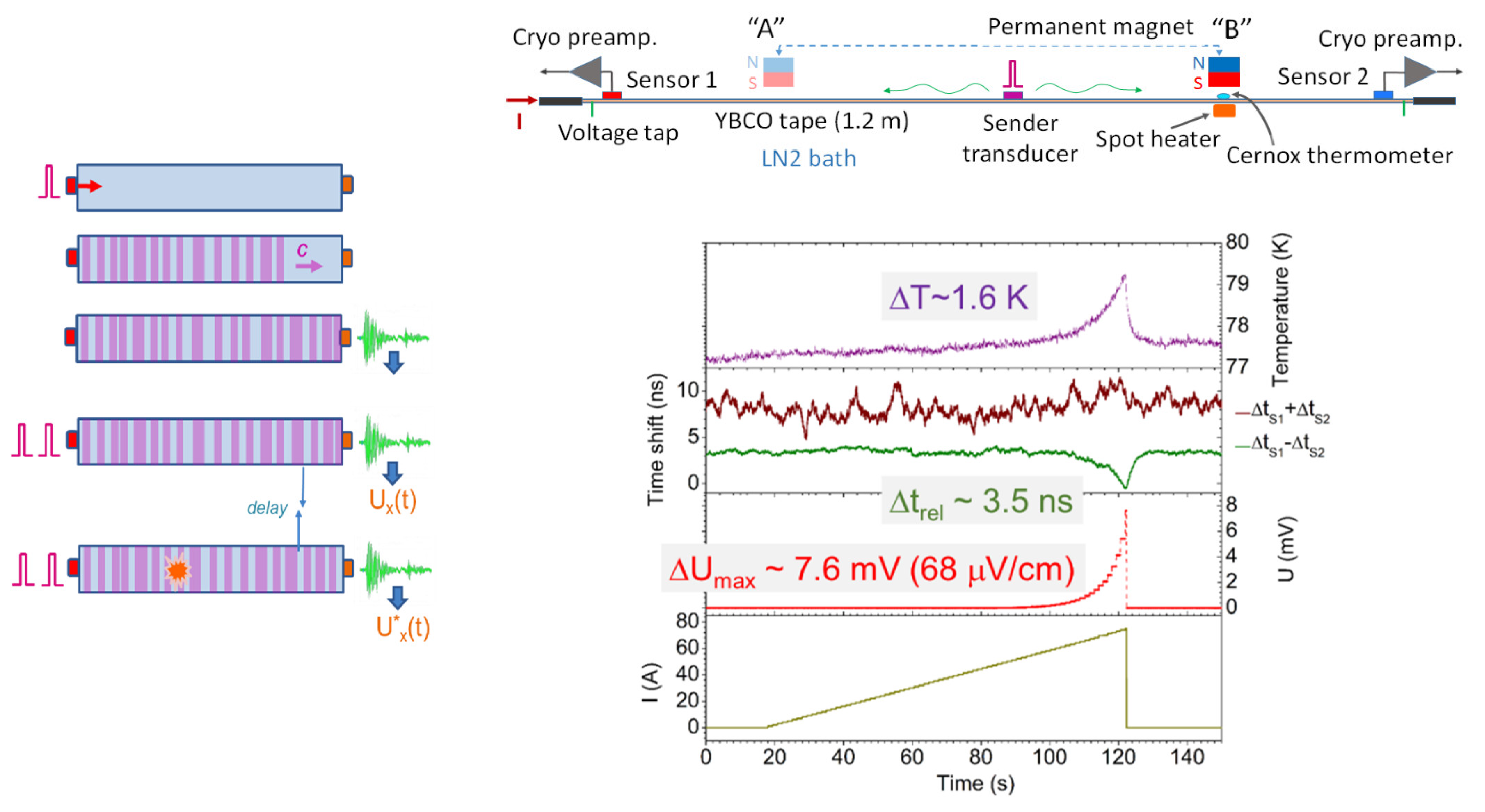
Figure 6.
(Left) Principle of active acoustic thermometry: diffuse ultrasonic wave (coda) is being monitored for a time shift caused by local temperature variations in the interior of a monitored object. (Right) Demonstration of the active acoustic quench detection in a 1.2 m long ReBCO tape conductor in liquid nitrogen, where time shift associated with a hot spot formation is clearly detected along with the resistive voltage (adopted from [83]).


Table 1.
A summary of non-voltage quench detection techniques.
| Magnetic Techniques | Quench Antennas |
|---|---|
| Hall Sensor Arrays | |
| Optical techniques | Fiber Bragg grating sensors |
| Rayleigh scattering | |
| Raman scattering, Brillouin scattering and specialized fibers | |
| Acoustic techniques | Passive (acoustic emission) |
| Active (diffuse wave ultrasonics) | |
| Capacitive techniques | Boiling of cryogenic liquids |
| RF-based techniques | Impedance change |
| Time–frequency domain reflectometry |
Publisher’s Note: MDPI stays neutral with regard to jurisdictional claims in published maps and institutional affiliations. |
© 2021 by the author. Licensee MDPI, Basel, Switzerland. This article is an open access article distributed under the terms and conditions of the Creative Commons Attribution (CC BY) license (https://creativecommons.org/licenses/by/4.0/).
Share and Cite
MDPI and ACS Style
Marchevsky, M. Quench Detection and Protection for High-Temperature Superconductor Accelerator Magnets. Instruments 2021, 5, 27. https://doi.org/10.3390/instruments5030027
AMA Style
Marchevsky M. Quench Detection and Protection for High-Temperature Superconductor Accelerator Magnets. Instruments. 2021; 5(3):27. https://doi.org/10.3390/instruments5030027
Chicago/Turabian StyleMarchevsky, Maxim. 2021. "Quench Detection and Protection for High-Temperature Superconductor Accelerator Magnets" Instruments 5, no. 3: 27. https://doi.org/10.3390/instruments5030027