
Additive Manufacturing of an IH-Type Linac Structure from Stainless Steel and Pure Copper


Institute of Applied Physics (IAP), Goethe University, 60438 Frankfurt, Germany
*
Author to whom correspondence should be addressed.
Instruments 2023, 7(3), 22; https://doi.org/10.3390/instruments7030022
Submission received: 18 July 2023
/
Revised: 1 August 2023
/
Accepted: 4 August 2023
/
Published: 7 August 2023
Abstract
:Additive manufacturing (AM) of metals has the potential to provide significant benefits for the construction of future particle accelerators. The combination of low cost manufacturing of complex geometries in combination with efficiency gains from improved linac design enabled by AM may be one way towards future cost-effective green accelerator facilities. As a proof of concept, we present a high-efficiency , MHz IH-DTL cavity based on an AM design. In this case, the complex internal drift tube structures with internal cooling channels have been produced from 1.4404 stainless steel and from pure copper using AM. The prototype cavity, as well as stainless steel AM parts have been electroplated with copper. We present results from successful vacuum tests, low level RF measurements of the cavity, as well as the status of preparations for high-power RF tests with a 30 kW pulsed power amplifier.
1. Introduction
Additive manufacturing (AM) of metal parts has the potential to provide new ways to manufacture linear accelerator cavities. AM of stainless steel is the state of the art in the mechanical parts production industry. The use of components made by AM in vacuum and RF applications is not as well established. Complex geometries, especially occluded inside the volume of a manufactured part are the strong suite of AM. Applying this to the design of linac cavities allows for substantial improvements of cooling channel geometries, especially for compact structures. This leads to a significant increase in the usable frequency range for high power H-mode structures. For an IH-type structure, the conventional limit would be around 300 MHz [1], which has already been surpassed by the prototype at 433.632 MHz presented in this publication. A further increase in frequency up to 800 MHz–1 GHz seems feasible, especially for higher order H-mode structures like a CH-DTL. In contrast to existing proposals for these higher frequencies, as in [2,3], AM-based linacs can potentially be operated at much higher power levels due to the inclusion of cooling geometries. Additionally, the relative freedom for design and production of various geometries, bears the potential for more efficient linac cavities by shape optimization. In recent years, a number of studies on the topic of AM for linear accelerator components have been published [4,5,6,7,8,9,10,11,12,13,14,15].
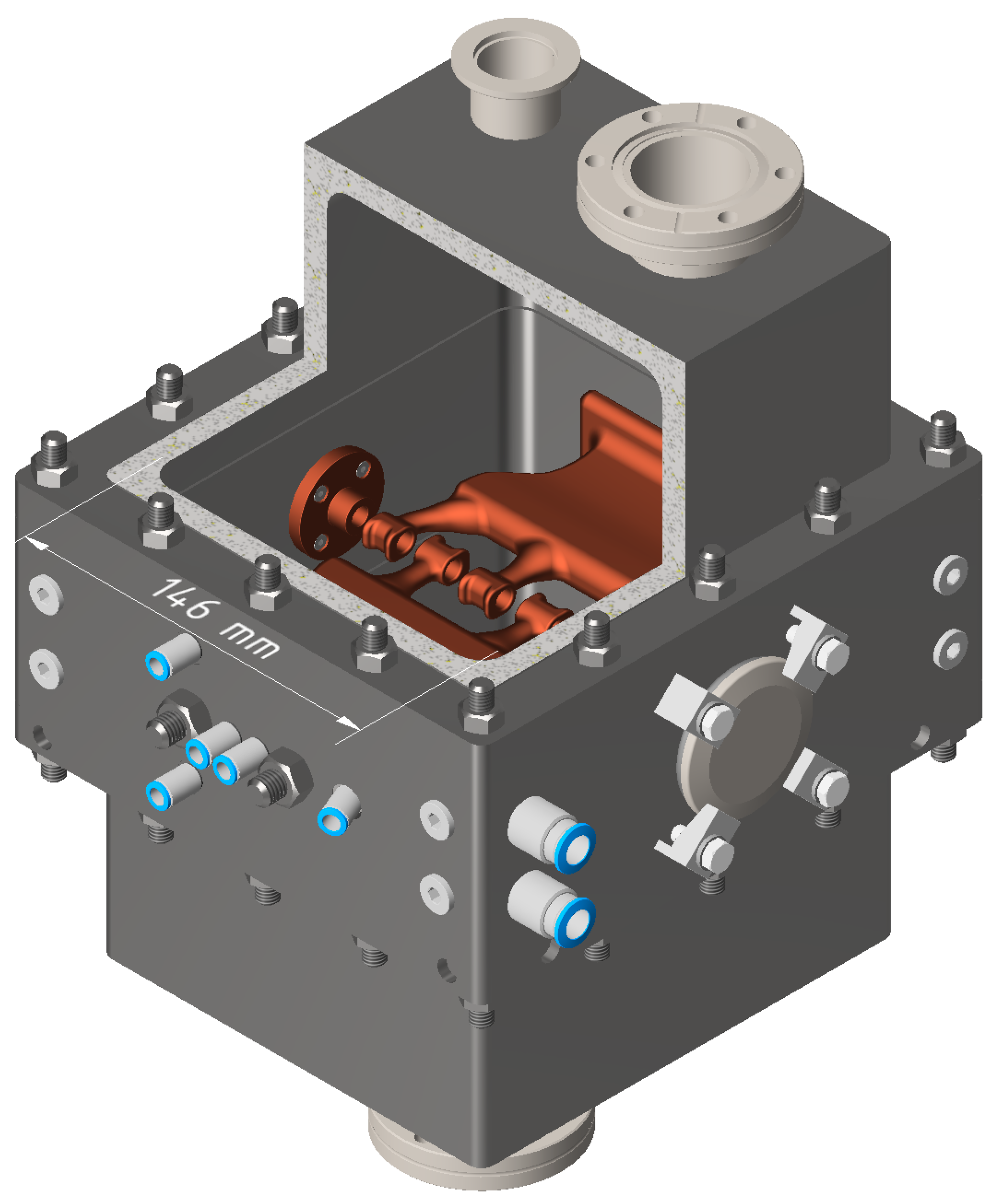
Motivated by successful preliminary vacuum studies with 3D printed pipes, a prototype IH-type linac cavity with a fully printed drift-tube structure was constructed (A CAD model of a current revision of this cavity is shown in Figure 1). The cavity is designed to be UHV capable and includes cooling channels reaching into the stems of the drift tube structure for power testing with a pulsed 30 kW RF amplifier. Since the first construction of the cavity in late 2020 to early 2021, several experiments have been conducted to evaluate certain aspects of the cavity suitability for linac operation. In the following, we will focus on the progress made since the reports in [4,13].
Prototype Design and Concept
A summary of the mechanical and RF paramters of the prototype design is given in Table 1. A modular approach was taken when designing the prototype. A precision mount inset into the center frame allows for reproducible positioning of the AM drift-tube structures. These can be exchanged for different styles or new revisions with relatively low effort. The prototype cavity was designed for a resonance frequency of 433.632 MHz, which is a harmonic of the GSI UNILAC operation frequency [16]. In combination with a targeted proton beam energy of 1.4 MeV this scenario allows for a compact accelerator beyond the conventional frequency limit [1] and, therefore, a good benchmark for the new approach of compact linac construction. For the idealized design model, the simulated effective shunt impedance is , showing the high efficiency of such an IH-type structure. The total acceleration voltage of the prototype is 1 MV, which corresponds to an accelerating gradient of 6.8 MV/m at the design RF power of 30 kW.
2. Full Cavity Vacuum Tests
The cavity was fully assembled in early May 2021. For first vacuum tests, the cavity was attached to a turbo-molecular pump (Pfeiffer HiPace80) via one of the top CF40 flanges. A vacuum gauge (Pfeiffer PKR261) was used to measure and log the cavity vacuum. The cavity lids, as well as the girder drift tube structures, were sealed using 1.5 mm aluminum wire. Following these measurements where a chamber pressure of only mbar was reached [4], the cavity was disassembled and revisions to sealing surfaces on the cavity frame and lids, as well as additional provisions for a dedicated pre-vacuum system were made.
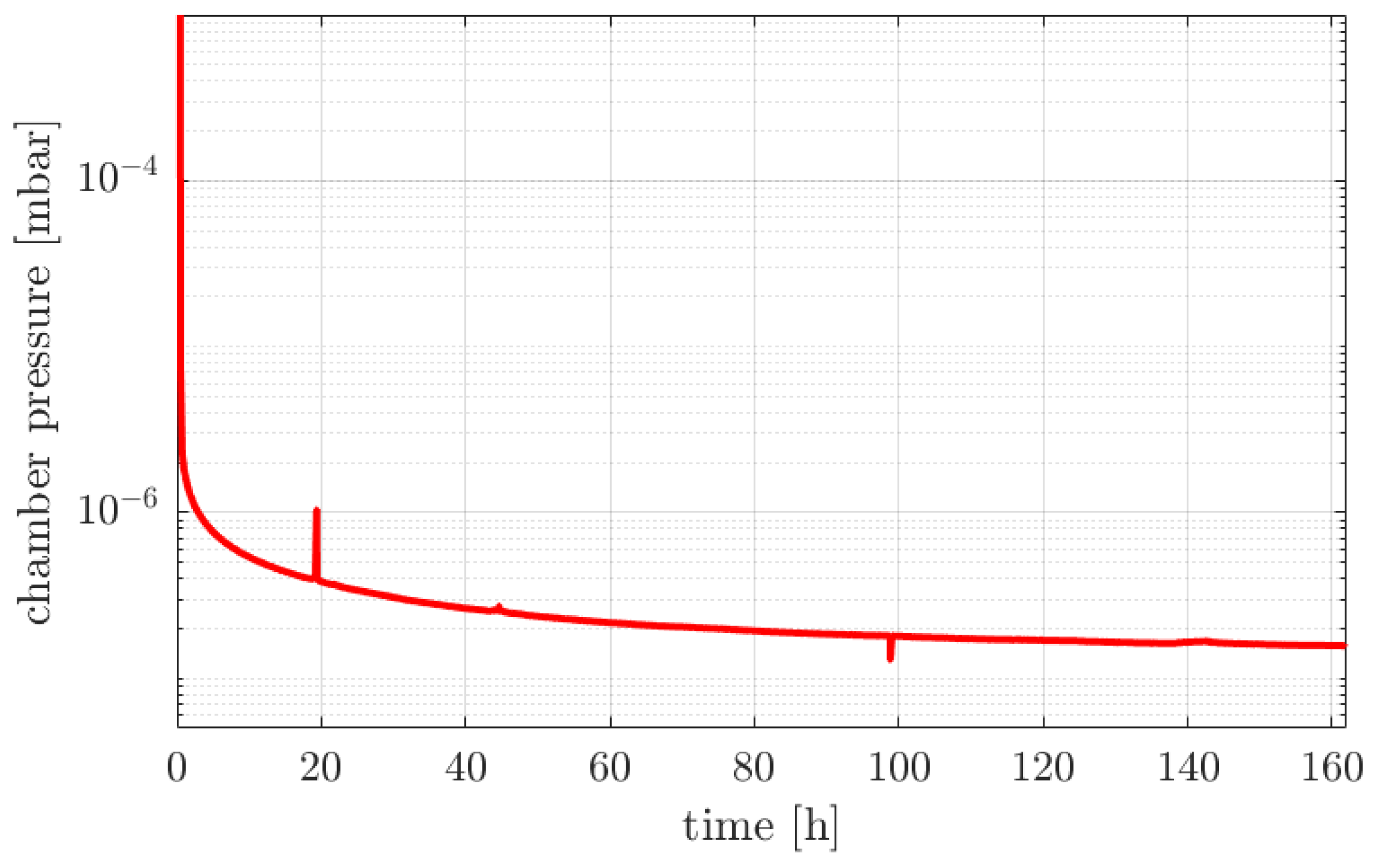
New vacuum measurements were performed in early 2022, where a pressure of mbar was reached using stainless steel AM parts. During the whole 160 h of measurement, no excessive or erratic outgassing was observed. It has to be noted, that while the cavity lids and frame were sealed on conventionally manufactured surfaces, the AM drift-tube structures inside the cavity also have sealing surfaces on the bottom which are also sealed using mm aluminum wire. This demonstrates that even direct vacuum sealing surfaces can be manufactured with 3D printing. Of course, the surface has to be milled flat after printing, as the surface roughness of a raw printed part would not suffice, but the material density and quality is suitable for HV to UHV applications. At the demonstrated vacuum level of mbar, it can be expected, that a base level vacuum of mbar is achievable without RF power. Therefore, high-power RF operation is expected to be performing as usual. A pump-down curve from these latest measurements is shown in Figure 2.
3. Polishing and Copper Plating
Due to the additive manufacturing process, the raw parts after manufacturing have a rough surface finish. Magnitude and type of the surface quality depends on the process parameters during the metal AM, but, in general, a surface roughness in the order of = 10–50 μm can be expected. At frequencies >100 MHz, this surface roughness is multiple times the skin depth in copper and can therefore be expected to significantly influence RF surface conductivity. Therefore, surface finishing to achieve sufficient surface quality for RF applications is an important research topic [12,13,17].
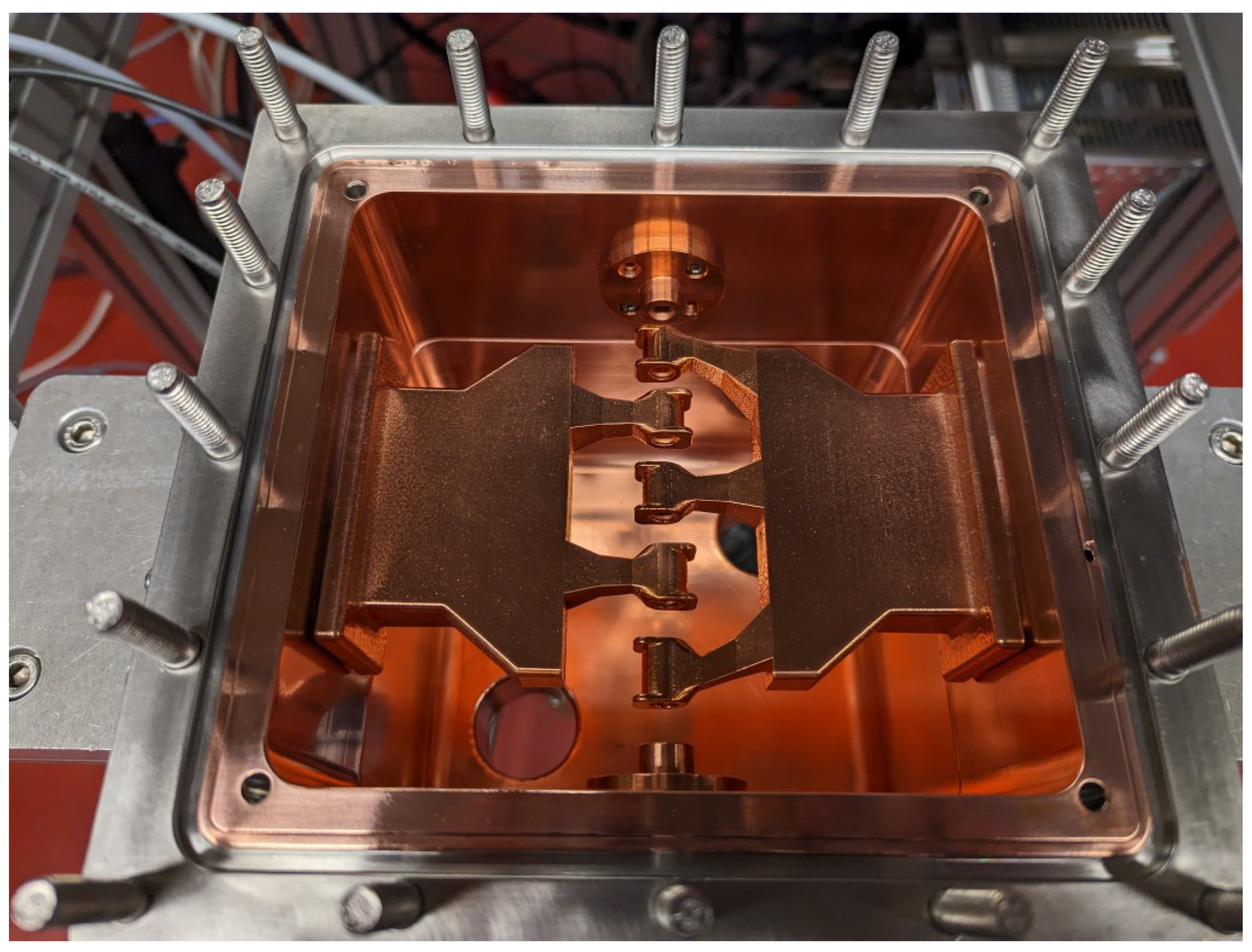
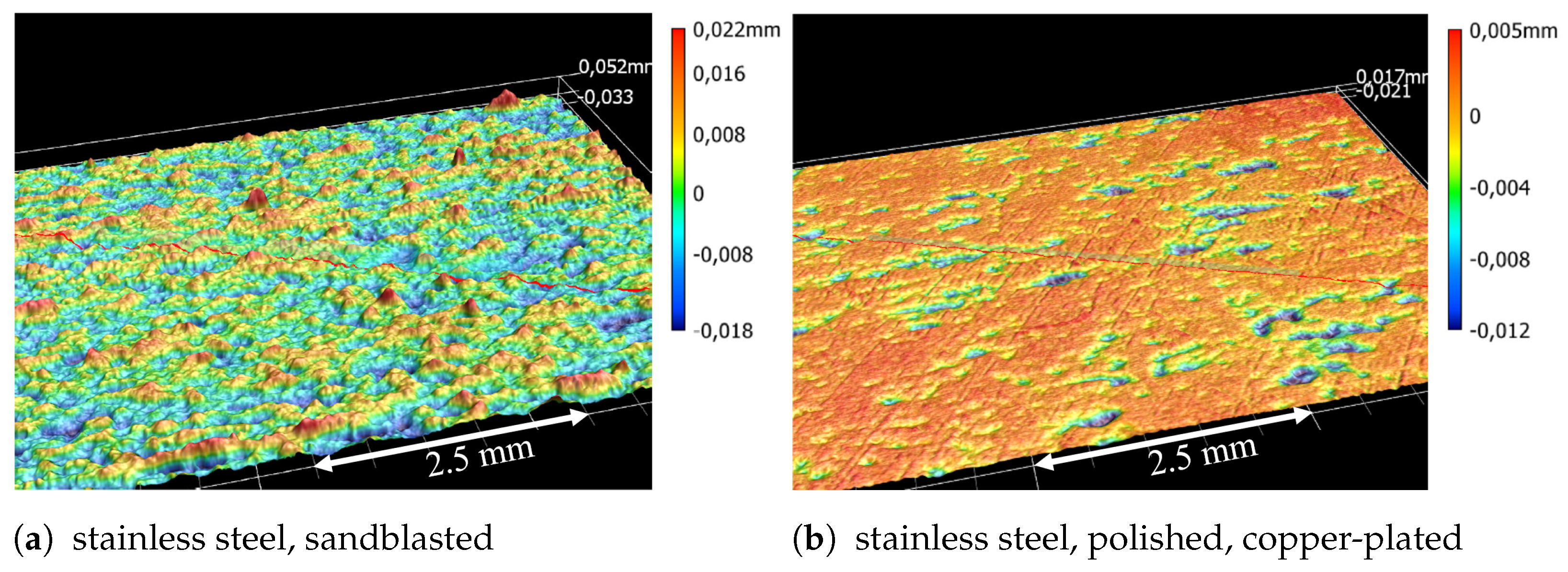
An initial batch of AM drift-tube structures has been polished in a slip grinding machine. The results are promising, however for the initial geometry there are some areas that cannot be reached by the granule particles. Following the surface polishing, the structures have been copper plated with an approximate layer thickness of 50 μm. In addition, the entire cavity walls have been electroplated with copper and assembled for testing (see Figure 3). Optical inspection shows a very clean result of the copper plating; however, microscopic surface scans show some remaining “valleys” in the polished and copper plated part (see Figure 4).
4. Girder Design Improvements
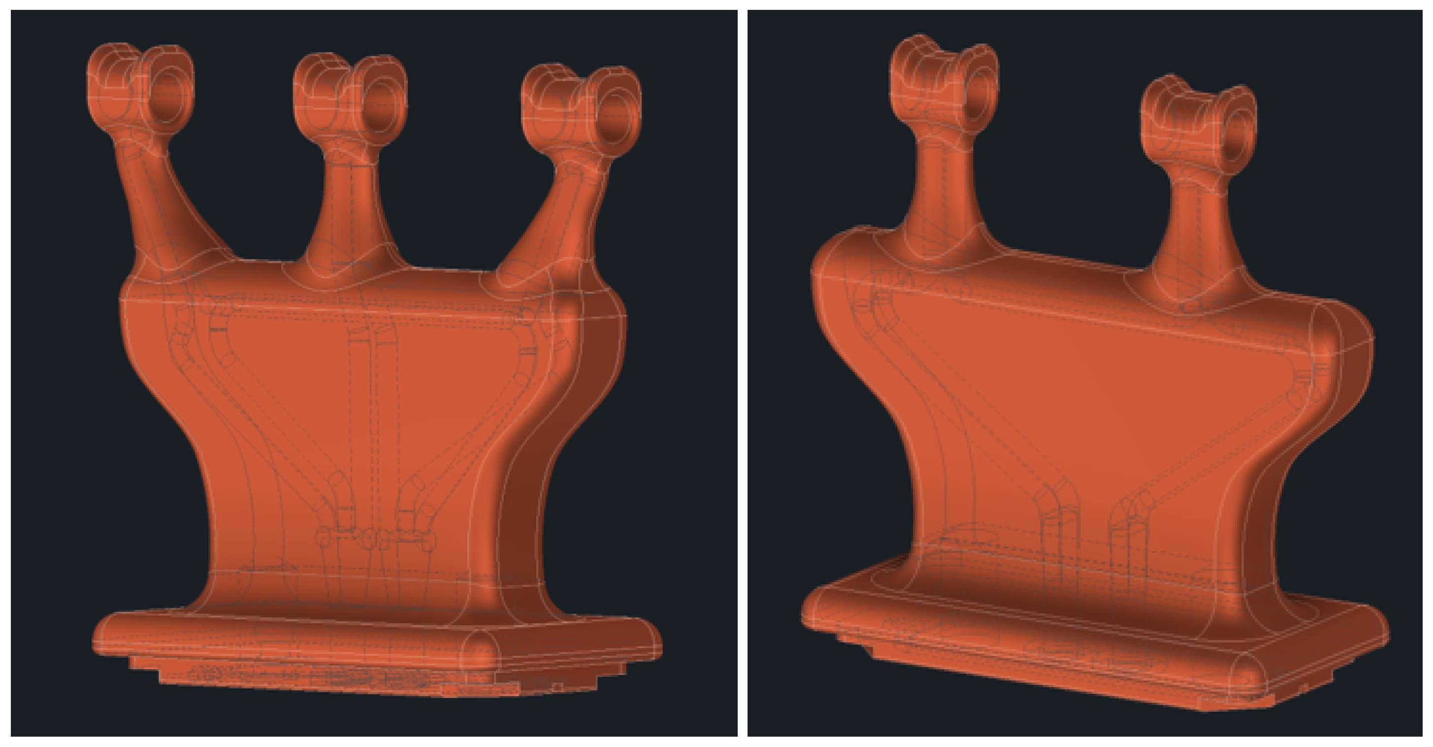
From polishing and copper plating tests, as well as RF simulations, it was clear, that the original geometry of the printed parts (see Figure 3) would not be suitable for high-power testing. Therefore, a significant redesign of the structure was performed. The new design is smoothing the overall geometry without sacrificing the RF performance (see Figure 5). Some hard to reach corners in the model were eliminated to better facilitate post-processing of the parts. Peak fields for the new design are significantly reduced, which will be beneficial for copper plating, as well as high-power RF operation. A CAD view of the improved geometry is shown in Figure 5. The new geometry also includes improved cooling channels for better flow in the thin stems on the top of the structure. The drift tubes have a visible bulge on top that is used to suppress the dipole components inherent for IH-type structures [18]. With these relatively small bulges, the dipole field components are reduced to about 1.5%. At that level, the impact on the beam dynamics are minimal.
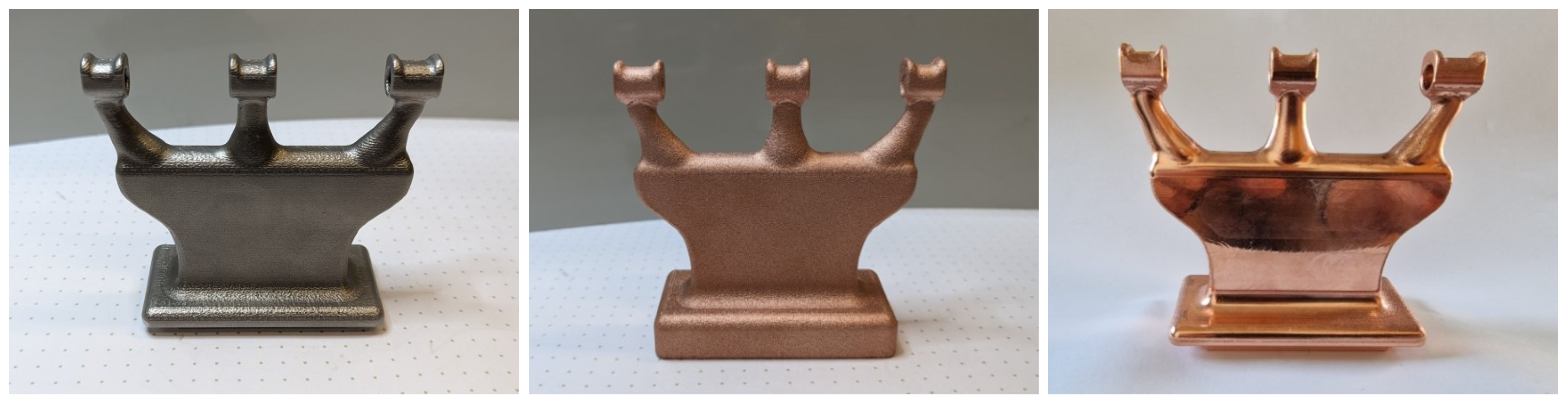
Figure 6 (left) shows the new geometry printed from stainless steel, where the bottom sealing surface and the beam aperture have been CNC milled while for the high-power RF tests the remaining surface will be polished and electroplated with copper. Figure 6 also shows the new geometry parts printed from pure copper before (middle) and after CNC post-processing (right). In this case, the whole part was CNC machined to produce the sealing surfaces, as well as to remove the outermost layer of the printed part (100 μm). The results show a near mirror finish of the pure copper parts. While these results are certainly impressive, machining the whole surface of the part is an expensive option and may also not be possible for all geometries. Following tests with copper parts will focus on polishing instead of CNC post-processing, to produce the most cost-effective solution.
5. Low-Level RF Tests
To assess the RF performance of different part combinations, low-level RF measurements were performed with a network analyzer to determine the frequency and Q-factor. For comparison, CST simulations were performed with the final design CAD geometry of the components, to become as close to the manufactured cavity as possible. The main differences to the ideal model are additional flange ports in the lids, recesses, and o-ring grooves for the sealing surfaces and the mounting ports of the AM structures. Therefore, the simulated shunt impedance of is slightly lower than the ideal values stated above. The CST simulations were performed with an electrical conductivity of 107 S/m and 106 S/m for copper and stainless steel, respectively.
Thanks to the modular design of the prototype cavity, measurements of several combinations of cavity and drift-tube structures have been performed since. Table 2 summarizes the measurement results and compares to ideal simulation values. For the original components, without any copper plating, the measured resonance frequency is only 79 kHz higher than simulated, indicating very good mechanical accuracy of the untreated parts. The measured unloaded quality factor of the cavity is also reasonably close to the simulated value of for stainless steel. Calculating the quality factor for stainless steel relies on the actual conductivity value of the steel used during manufacturing and can, therefore, only be approximated based on spec-sheets. Exchanging the bare steel AM parts with copper-plated parts, about more than doubles the measured Q-factor due to the improvement in conductivity . However, we observe a significant drop in resonance frequency by about 6 MHz. This can be attributed to two geometrical effects: the increased drift-tube lengths, as well as the mounting height of the AM parts, due to the additional layer of copper from electroplating, which both lead to a change in frequency. These effects and their magnitude have been simulated and can explain the frequency shift considering copper layers of about 100 μm. Finally for the initial AM parts geometry, a measurement with the copper-plated cavity and copper-plated AM parts yields a Q-factor of , which is only 19% below the ideal simulated value. It might be speculated, that with a more uniform surface finish before copper plating, these results might be further improved.
The most recent results were produced with the pure copper AM parts inside the copper-plated cavity. These parts are of the new geometry (as in Figure 5). Simulations showed no significant difference in quality factor for the different girder geometries ( vs. ). The printed copper parts were CNC machined to remove the surface layer and produce a low roughness surface. Machining parameters were based on the original CAD model with a best fit approach. The targeted material removal was 100 μm of the surface of the part. Due to some areas being smaller than spec, those were machined less. Overall, the sides and plane faces could be finished to low surface roughness, while especially the girder overhangs retained some roughness. The measured quality factor for these copper parts is much lower than expected , indicating significantly lower conductivity than that of pure copper. While bulk DC conductivity of these “pure” copper AM parts may be identical to bulk copper, due to the skin depth of only 3.1 μm at 433.632 MHz, linac applications are much more sensitive to surface layer defects. Similar results with unexpectedly low Q-factor were reported in [15] for a 3 GHz DTL, while more recent results hint towards an influence of the outermost surface layers [17] whose removal can improve AM copper conductivity. A possible factor on the conductivity of the AM copper parts is the specific crystalline structure of the material due to the laser melting process [19]. To see, if an issue with the crystalline structure contributes to the loss in conductivity, the AM copper parts were annealed at 300–400 °C for one hour to allow re-crystallization of the copper. Following RF measurements show an improvement of the Q-factor to , which is an improvement of 18.5%. This is still 22% below the simulated value for the new geometry (AMV3). So as with the copper-plated parts, possible room for improvement may still be found. Further dedicated investigations into the RF conductivity of pure copper AM parts are inevitable.
6. RF Coupler Prototype
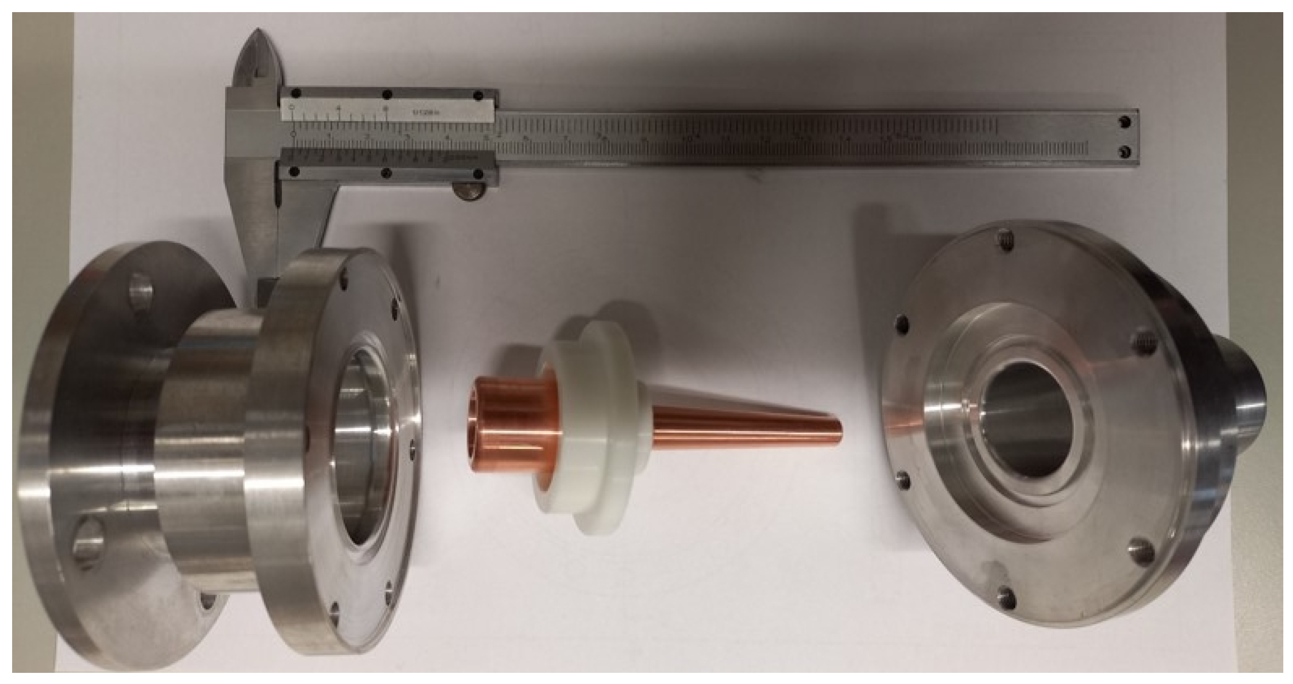
As the largest coupling port on the cavity is CF40, a compact RF coupler is needed for power tests. A prototype for a CF40 power coupler has been designed and tested (see Figure 7. While this version will not withstand high-power operation, the proof of concept for a small inductive coupler was successful. Using the prototype coupler, critical coupling with dB was achieved at the copper plated cavity with copper plated AM parts. Full power tests will be conducted with a dedicated solid state amplifier, capable of 30 kW pulsed operation (2 ms, 10 Hz), which has been delivered. The maximum average power transmitted through the coupler is therefore only 600 W and a simple coupler construction based on the existing coupler prototype will be used for first tests and conditioning of the cavity. A high power capable water-cooled version of the coupler is being developed for future tests.
7. Discussion
Most recent vacuum tests showed that a cavity pressure of mbar could be reached without issue using stainless steel AM parts. Low-level RF measurements of different part combinations show a promising trend for the usability of 3D printed parts as main components for accelerators. Copper-plated stainless steel structures have been shown to provide suitable vacuum performance in combination with high RF conductivity. Better control of the surface roughness by post-processing, and therefore a more uniform copper surface from electroplating, may have a positive effect on the conductivity. Additionally, first RF measurement results of AM pure copper parts tell a more complicated story. While the surface finish after CNC machining was mirror-like on most of the parts, the Q-factor, and therefore conductivity, was below the expected values. Annealing the copper parts to allow for re-crystallisation restored conductivity to a similar level compared with simulations as the copper-plated parts. In both the copper-plated stainless steel parts, as well as the pure copper AM parts there is potential for improvement. For classical IH-type structures, typically about 90% of the simulated Q-factor are achievable. This will be the focus of further investigations, along with high-power tests to be conducted on both variants.
Author Contributions
Conceptualization, H.H.; Methodology, H.H.; Software, H.H.; Validation, H.H.; Formal analysis, H.H. and A.A.; Investigation, H.H., A.A. and B.D.; Resources, H.H. and U.R.; Data curation, H.H.; Writing—original draft, H.H.; Writing—review & editing, H.H., A.A., B.D. and U.R.; Visualization, H.H.; Supervision, H.H. and U.R.; Project administration, H.H. and U.R.; Funding acquisition, H.H. and U.R. All authors have read and agreed to the published version of the manuscript.
Funding
This research was funded by the German Federal Ministry of Education and Research (BMBF), grant number 05P21RFRB2.
Data Availability Statement
Data is contained within the article.
Acknowledgments
We would like to acknowledge the support by the GSI Technology Laboratory (T. Dettinger) for annealing of the pure copper parts.
Conflicts of Interest
The authors declare no conflict of interest.
Abbreviations
The following abbreviations are used in this manuscript:
| AM | Additive Manufacturing |
| IH-DTL | Interdigital H-Mode Drift Tube Linear Particle Accelerator |
| CH-DTL | Crossbar H-mode Drift Tube Linear Particle Accelerator |
| DTL | Drift Tube Linear Particle Accelerator |
| RF | Radio Frequency |
| CAD | Computer-Aided Design |
| CNC | Computerized Numerical Control |
| HV | High Vacuum |
| UHV | Ultra-High Vacuum |
| linac | Linear Particle Accelerator |
References
- Ratzinger, U. H-type linac structures. In CAS-CERN Accelerator School: Radio Frequency Engineering; CERN: Meyrin, Switzerland, 5 August 2005; p. 351. [Google Scholar] [CrossRef]
- Benedetti, S.; Grudiev, A.; Latina, A. Design of a 750 MHz IH Structure for Medical Applications. In Proceedings of the LINAC’16, East Lansing, MI, USA, 26 September 2016; pp. 240–243. [Google Scholar] [CrossRef]
- Nakazawa, Y.; Cicek, E.; Futatsukawa, K.; Fuwa, Y.; Hayashizaki, N.; Iijima, T.; Iinuma, H.; Iwata, Y.; Kondo, Y.; Mibe, T.; et al. High-power test of an interdigital H-mode drift tube linac for the J-PARC muon g − 2 and electric dipole moment experiment. Phys. Rev. Accel. Beams 2022, 25, 110101. [Google Scholar] [CrossRef]
- Hähnel, H.; Ratzinger, U. First 3D Printed IH-Type Linac Structure—Proof-of-Concept for Additive Manufacturing of Linac RF Cavities. Instruments 2022, 6, 9. [Google Scholar] [CrossRef]
- Torims, T.; Pikurs, G.; Gruber, S.; Vretenar, M.; Ratkus, A.; Vedani, M.; López, E.; Brückner, F. First Proof-of-Concept Prototype of an Additive Manufactured Radio Frequency Quadrupole. Instruments 2021, 5, 35. [Google Scholar] [CrossRef]
- Frigola, P.; Agustsson, R.B.; Faillace, L.; Murokh, A.Y.; Ciovati, G.; Clemens, W.A.; Dhakal, P.; Marhauser, F.; Rimmer, R.A.; Spradlin, J.K.; et al. Advance Additive Manufacturing Method for SRF Cavities of Various Geometries. In Proceedings of the 17th International Conference on RF Superconductivity (SRF’15), Whistler, BC, Canada, 13–18 September 2015; pp. 1181–1184. [Google Scholar]
- Jenzer, S.; Alves, M.; Delerue, N.; Gonnin, A.; Grasset, D.; Letellier-Cohen, F.; Mercier, B.; Mistretta, E.; Prevost, C.; Vion, A.; et al. Study of the Suitability of 3D Printing for Ultra-High Vacuum Applications. In Proceedings of the 8th International Particle Accelerator Conference (IPAC’17), Copenhagen, Denmark, 14–19 May 2017; pp. 3356–3358. [Google Scholar] [CrossRef]
- Sattonnay, G.; Alves, M.; Bilgen, S.; Bonnis, J.; Brisset, F.; Gonnin, A.; Grasset, D.; Jenzer, S.; Letellier-Cohen, F.; Mercier, B.; et al. Is it Possible to Use Additive Manufacturing for Accelerator UHV Beam Pipes? In Proceedings of the 10th International Particle Accelerator Conference (IPAC’19), Melbourne, VIC, Australia, 19–24 May 2019; pp. 2240–2243. [Google Scholar] [CrossRef]
- Delerue, N.; Carduner, H.; Gerard, R.L.; Jenzer, S.; Manil, P.; Repain, P.; Simar, A. Prospects of Additive Manufacturing for Accelerators. In Proceedings of the 10th International Particle Accelerator Conference (IPAC’19), Melbourne, VIC, Australia, 19–24 May 2019; pp. 4118–4120. [Google Scholar] [CrossRef]
- Terrazas, C.A.; Mireles, J.; Gaytan, S.M.; Hinojos, A.; Frigola, P.; Wicker, R.B. Fabrication and characterization of high-purity niobium using electron beam melting additive manufacturing technology. Int. J. Adv. Manuf. Technol. 2016, 84, 1115–1126. [Google Scholar] [CrossRef]
- Riensche, A.; Carriere, P.; Smoqi, Z.; Menendez, A.; Frigola, P.; Kutsaev, S.; Araujo, A.; Araujo, N.G.; Rao, P. Application of hybrid laser powder bed fusion additive manufacturing to microwave radio frequency quarter wave cavity resonators. Int. J. Adv. Manuf. Technol. 2023, 124, 619–632. [Google Scholar] [CrossRef]
- Torims, T.; Ahmed, C.; Nicolas, D.; Maurizio, F.P.; Dagnija, K.; Elena, L.; Tauno, O.; Guntis, P.; Mateo, P. Evaluation of geometrical precision and surface roughness quality for the additively manufactured radio frequency quadrupole prototype. J. Phys. Conf. Ser. 2023, 2420, 012089. [Google Scholar] [CrossRef]
- Hähnel, H.; Ateş, A.; Dedić, B.; Ratzinger, U. Pure Copper and Stainless Steel Additive Manufacturing of an IH-Type Linac Structure. In Proceedings of the IPAC’23, Venezia, Italy, 7–12 May 2023; pp. 4880–4883. [Google Scholar]
- Wolf, C.R.; Beck, F.B.; Franz, L.; Neumaier, V.M. 3D Printing for High Vacuum Applications. In Proceedings of the 22nd International Conference on Cyclotrons and Their Applications (Cyclotrons’19), Cape Town, South Africa, 22–27 September 2019; pp. 317–320. [Google Scholar] [CrossRef]
- Mayerhofer, M.; Mitteneder, J.; Dollinger, G. A 3D printed pure copper drift tube linac prototype. Rev. Sci. Instrum. 2022, 93, 023304. [Google Scholar] [CrossRef] [PubMed]
- Schlitt, B.; Eichler, G.; Hermann, S. Modernisation of the 108 MHz RF Systems at the GSI UNILAC. In Proceedings of the LINAC’16, East Lansing, MI, USA, 25–30 September 2016; pp. 898–901. [Google Scholar] [CrossRef]
- Mayerhofer, M.; Mitteneder, J.; Wittig, C.; Prestes, I.; Jägle, E.; Dollinger, G. First High Quality DTL Cavity additively Manufactured from Pure Copper. In Proceedings of the IPAC’23, Venezia, Italy, 7–12 May 2023; Volume 5, pp. 4912–4915. [Google Scholar]
- Ratzinger, U. Interdigital RF Structures. In Proceedings of the LINAC’90, Albuquerque, NM, USA, 9–14 September 1990; paper WE201; pp. 525–529. [Google Scholar]
- Fonda, R.W.; Rowenhorst, D.J. Crystallographic Variability in Additive Manufacturing. IOP Conf. Ser. Mater. Sci. Eng. 2022, 1249, 012007. [Google Scholar] [CrossRef]
Figure 1.
Cross-section of the 433.632 MHz IH-type cavity CAD model with revised AM inner drift-tube structure.
Figure 1.
Cross-section of the 433.632 MHz IH-type cavity CAD model with revised AM inner drift-tube structure.

Figure 2.
Pump-down curve of the fully assembled cavity after revision and reassembly in 2022. Peak at 20 h corresponds to opening of the dedicated pre-vacuum valve.
Figure 2.
Pump-down curve of the fully assembled cavity after revision and reassembly in 2022. Peak at 20 h corresponds to opening of the dedicated pre-vacuum valve.

Figure 3.
Copper-plated cavity with copper-plated stainless steel AM structures mounted.

Figure 4.
(a) Surface scan of a stainless steel AM drift-tube structure after manufacturing and light sandblasting. Surface roughness μm. (b) Exemplary surface profile after copper plating the slip grinding polished AM drift-tube structure. Surface roughness μm. Measured on Keyence VR6000.
Figure 4.
(a) Surface scan of a stainless steel AM drift-tube structure after manufacturing and light sandblasting. Surface roughness μm. (b) Exemplary surface profile after copper plating the slip grinding polished AM drift-tube structure. Surface roughness μm. Measured on Keyence VR6000.

Figure 5.
CAD models of the improved geometry for the AM IH-structure.

Figure 6.
New geometry printed in 1.4404 stainless steel (left), pure copper (middle) and after CNC machining of the copper part (right). Bottom surface and beam apertures have been CNC machined as well on both steel and copper parts.
Figure 6.
New geometry printed in 1.4404 stainless steel (left), pure copper (middle) and after CNC machining of the copper part (right). Bottom surface and beam apertures have been CNC machined as well on both steel and copper parts.

Figure 7.
CF40 power coupler prototype disassembled.


Table 1.
Mechanical and RF Parameters of the AM IH-DTL prototype cavity.
| General Parameters | Value |
|---|---|
| Resonance Frequency: | 433.632 MHz |
| Outer Dimensions (w/l/h): | 221 mm/206 mm/261 mm |
| Inner Length: | 146 mm |
| Period Length (): | 19 mm–24 mm |
| Reference Particle: | proton |
| Initial Energy: | 1.4 MeV |
| Final Energy: | 2.4 MeV |
| Simulation Results (ideal model) | Value |
| Unloaded Q-factor: | 8601 |
| RF losses for 1 MV: | 24.8 kW |
| Effective Shunt Impedance: |
Table 2.
Comparison of CST Microwave Studio RF simulation based on the final CAD model and low level RF measurements for different configurations of unplated steel, copper-plated steel and bulk Cu AM parts. Initial AM drift-tube structure: (original AM geometry), new geometry AM parts (new AM geometry). Where marked with *, the AM parts were sealed using indium wire instead of aluminum wire.
| CST Simulation | ||
|---|---|---|
| (original AM geometry): steel conductivity | 433.4 MHz | 1321 |
| (original AM geometry): copper conductivity | 433.4 MHz | 8715 |
| (new AM geometry): copper conductivity | 432.0 MHz | 8300 |
| Measurement-Stainless Steel Cavity | ||
| (original AM geometry): steel | 433.5 MHz | 1132 |
| (original AM geometry): copper plated steel | 427.3 MHz | 2600 |
| Measurement-Copper Plated Cavity | ||
| (original AM geometry): copper plated steel | 428.3 MHz | 7076 |
| (new AM geometry) *: pure copper | 438.6 MHz | 5200 |
| (new AM geometry) *: pure copper, annealed | 438.6 MHz | 6402 |
Disclaimer/Publisher’s Note: The statements, opinions and data contained in all publications are solely those of the individual author(s) and contributor(s) and not of MDPI and/or the editor(s). MDPI and/or the editor(s) disclaim responsibility for any injury to people or property resulting from any ideas, methods, instructions or products referred to in the content. |
© 2023 by the authors. Licensee MDPI, Basel, Switzerland. This article is an open access article distributed under the terms and conditions of the Creative Commons Attribution (CC BY) license (https://creativecommons.org/licenses/by/4.0/).
Share and Cite
MDPI and ACS Style
Hähnel, H.; Ateş, A.; Dedić, B.; Ratzinger, U. Additive Manufacturing of an IH-Type Linac Structure from Stainless Steel and Pure Copper. Instruments 2023, 7, 22. https://doi.org/10.3390/instruments7030022
AMA Style
Hähnel H, Ateş A, Dedić B, Ratzinger U. Additive Manufacturing of an IH-Type Linac Structure from Stainless Steel and Pure Copper. Instruments. 2023; 7(3):22. https://doi.org/10.3390/instruments7030022
Chicago/Turabian StyleHähnel, Hendrik, Adem Ateş, Benjamin Dedić, and Ulrich Ratzinger. 2023. "Additive Manufacturing of an IH-Type Linac Structure from Stainless Steel and Pure Copper" Instruments 7, no. 3: 22. https://doi.org/10.3390/instruments7030022