A Finger Exoskeleton Robot for Finger Movement Rehabilitation

Department of Mechanical Engineering, National Central University, Taoyuan 32001, Taiwan
*
Author to whom correspondence should be addressed.
Inventions 2017, 2(3), 12; https://doi.org/10.3390/inventions2030012
Submission received: 23 April 2017
/
Revised: 24 June 2017
/
Accepted: 28 June 2017
/
Published: 1 July 2017
(This article belongs to the Special Issue Advances in Mechanism Design for Robots)
Abstract
:In this study, a finger exoskeleton robot has been designed and presented. The prototype device was designed to be worn on the dorsal side of the hand to assist in the movement and rehabilitation of the fingers. The finger exoskeleton is 3D-printed to be low-cost and has a transmission mechanism consisting of rigid serial links which is actuated by a stepper motor. The actuation of the robotic finger is by a sliding motion and mimics the movement of the human finger. To make it possible for the patient to use the rehabilitation device anywhere and anytime, an Arduino™ control board and a speech recognition board were used to allow voice control. As the robotic finger follows the patients voice commands the actual motion is analyzed by Tracker image analysis software. The finger exoskeleton is designed to flex and extend the fingers, and has a rotation range of motion (ROM) of 44.2°.

1. Introduction
Statistically, one in six people in the world will have a stroke [1] at some time, or develop some debilitating bone condition. Most strokes are caused by an interruption of the blood supply to part of the brain. It is very important for stroke patients to move the parts of the body that have been affected to restore and retrain movement. This rehabilitation is very important for the patient and is particularly so for the achievement of full movement. This not only helps to maintain muscle tension and strength, and increase durability, but also promotes blood circulation [2].
Rehabilitation systems have been extensively studied for effective restoration and training of muscle activity in the arm or hand [3,4]. The degree of upper limb rehabilitation is also used in clinical tests [5]. However, a finger exoskeleton is more difficult to design than one for the arm because it requires many more degrees of freedom (DOF) of motion and this involves small moving parts [6]. The design of a typical finger mechanism is complicated, has involved control requirements, and is usually very expensive. To reduce the cost and simplify the fabrication and operation, many people working on the problem began to use underactuated mechanisms in the design of a robot finger [7,8].
An underactuated mechanism has fewer driving sources than the number of DOF. Such an underactuated finger mechanism can be simple in structure, and is easily made even simpler by linking the motion of individual joints, or linking the motion of one finger to another finger [9]. Tendon-actuated and linkage mechanisms are the most common underactuated mechanisms in current use. However, the development and progress of robotic engineering has allowed the underactuated robot to include more DOF and has also lowered the complexity in many different applications.
A tendon-driven mechanism [10] can simply use a nylon line to stretch and bend the fingers. It has the advantage of simplicity and also absorbs shock; however, the line itself is under tension, which puts more load on the finger joints that increases friction forces, and is itself subject to elastic deformation. This kind of mechanism can only be used under a small load. Linkage-type mechanisms driven by auxiliary links to control the fingers have advantages. They are easy to analyze and mechanically rigid, but the many links lead to a loose structure and a humanoid robot finger comparable in size to that of a real finger is not easy to achieve [11].
Various hand exoskeleton technologies for rehabilitation and assistive robotics have recently been developed [12]. To design a proper hand or finger exoskeleton, the biomechanics of the hand/finger, robotic mechanisms, and control methods must be considered. Hand exoskeletons can be driven by different actuators, including electric actuators, pneumatic actuators, and smart material actuators [12]. Allota [13] used external servo motors to drive the exoskeleton fingers, whereas the radio control (RC) servomotors pulled the cables to actuate the fingers in the opening or closure phase. Polygerinos [14] used a soft pneumatic glove to produce bending motions to follow the motion of human fingers.
In this paper, a rehabilitative robotic finger is presented that can be used to maintain muscle strength through repetitive action, which also has the effect of functional recovery by rebuilding the sensorimotor links through the reorganization process in the damaged brain. To avoid the limitations of the heavy and bulky exoskeleton, the design of the finger used an underactuated mechanism, and a 3D printer was used to fabricate a prototype. Thus, the exoskeleton is affordable and competes with conventional therapy costs. In continuous passive motion therapy, a patient usually cannot control the movement through conscious effort; therefore, we used auto speech recognition to help patients control rehabilitation efforts themselves. A specific key word was used to start the robot and a carefully chosen stepper motor was used to power the mechanism. The actual motion was analyzed using the Open Source Physics tool, Tracker.
2. Design and Simulation
The design of the exoskeleton robot was undertaken with a number of important considerations in mind, the most pertinent of which were shape, size, cost, and weight. The weight and cost of the exoskeleton are critical to the users. In our design, the cost (around 30 US dollars) is affordable and competes with conventional therapy costs, while the weight is less than 45 grams. The device needed to fit on a finger and its movement had to follow the finger of the disabled patient. Before embarking on the project, we first studied finger bending motion as well as the general structure of finger muscles and bones. The input torque is set to 30 N-mm according to the motor selected. In the experiment, this torque can move the finger slowly, which is suitable for slight stroke patients. For moderate stroke patients, a higher torque motor with a similar size can be selected with a slight increase of cost and weight. We used Solidworks™ and Autodesk Inventor™ to both design and analyze the system.
2.1. Design
The slider-type robotic finger we designed can be divided into two main parts: the slider itself and the N-shaped linkage, as shown in Figure 1. The design concept of the slider mechanism was to locate the centers of the two arc-shaped sliders on the proximal and distal finger joints separately and to ensure the robotic finger followed human finger motion. In addition, the N-shaped linkage mechanism was designed to connect the proximal and distal arc-shaped sliders and to make them bend together. The N-shaped linkage used is simple and reduced the size of the finger.
The prototype robotic finger has three sliders, five links, ten bolts, and one motor. As the motor rotates, the blue crank moves the gray coupler forwards or backwards. The gray coupler pushes and pulls the yellow slider arm, making it move along the slot. When the yellow slider moves, this causes the green link, or N-shaped linkage, to rotate, which in turn causes the yellow and outer red sliders to move together. The N-shaped linkage continues to push and pull the outer red slider, causing it to move along the slot. The outer red slider connects to the human finger and causes it to bend.
2.2. Simulation
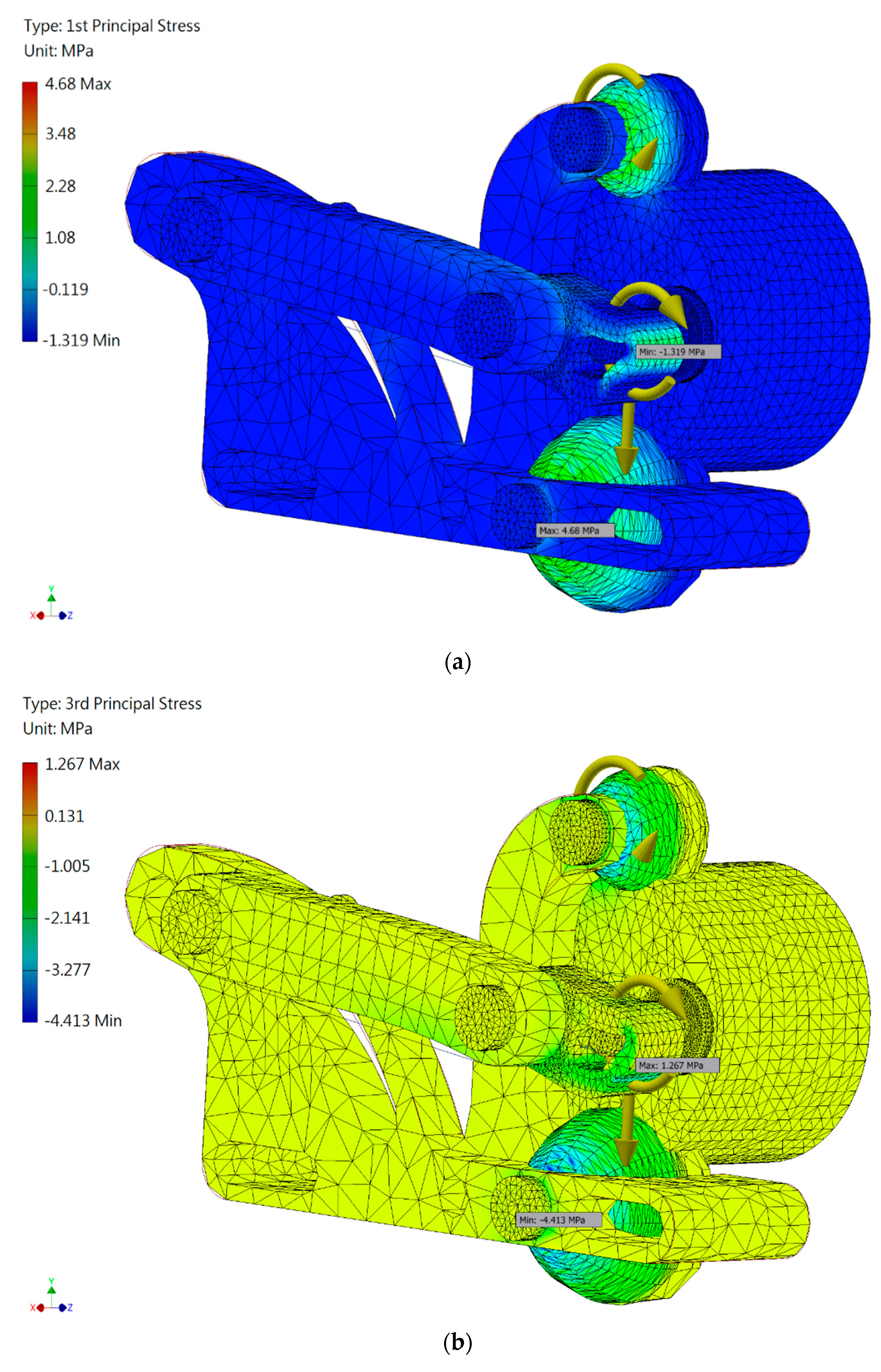
We used Autodesk Inventor™ for finite element analysis. We set the input torque to 30 N-mm according to the motor specifications. The average size of the mesh elements was 0.05 mm, and the smallest element was 0.5 times the average size. The material used to make the 3D print was PLA (Poly Lactic Acid). Although PLA is brittle at room temperature, it is widely used in biomedical engineering because it is both biodegradable and biocompatible. However, these qualities can lead to a decrease in mechanical strength, so we applied the maximum normal stress fracture criterion in the evaluation. This criterion states that failure will occur when the maximum (normal) principal stress reaches either the uniaxial tension strength or the uniaxial compression strength. Using these criteria, we evaluated the feasibility of the design, focusing on the stress close to the shaft, where fracture was most likely to occur. As can be seen in Figure 2, the maximum normal stress is about 4.68 MPa and, according to the data sheet, the maximum tensile strength of PLA is about 20 MPa. The safety factor was calculated to be 4.3. This means that PLA is suitable for the purpose with respect to strength. Table 1 shows the simulation results.
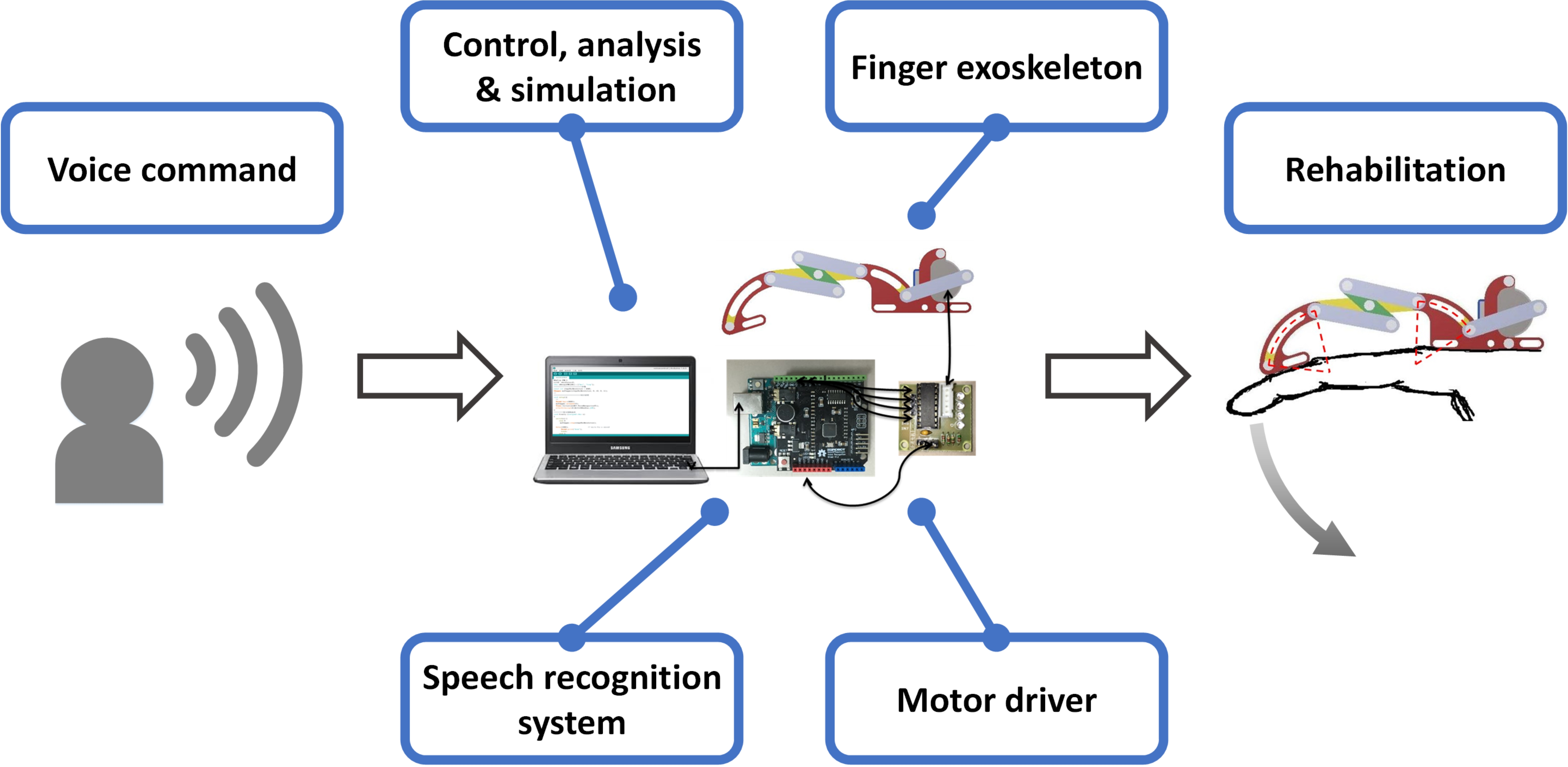
3. Experiment
The experimental setup is shown in Figure 3. First, we used speech commands to control the Arduino with a voice recognition board. A driving circuit was used to control the stepper motor installed on the finger exoskeleton robot, which then obeyed user voice commands. A stepper motor was used to drive the finger and the focus was on the problem of motor selection and control.
3.1. Control
Our goal was the design of a simple robotic finger that could be used for finger movement rehabilitation that did not involve too much overhead. We chose a motor as an actuator rather than hydraulics to avoid the complication of hydraulic lines [15]. Torque and size were the two most important factors considered when the motor was selected. As a rule, torque is almost proportional to size and we selected a 28BYJ-48 stepper motor, which includes a gear train with a reduction ratio of 64:1. We decided to use two-phase excitation, which gives the greatest torque, to ensure that there was enough power to drive the device, and coded our program accordingly.
Several control methods were available for use with the Arduino device, muscle electrical signals [16], a brain-computer interface (BCI) [17], and speech recognition [18]. For a BCI system, attention level is a common index. However, reliability is an issue in the case of rehabilitation and this is also a problem with muscle control. We chose speech recognition, which converts speech to text, to control our finger mechanism. Here, a voice reference (command) is stored in the system and compared with a received signal. If the signal corresponds to one of the prerecorded commands, the motor will start and the device will begin working.
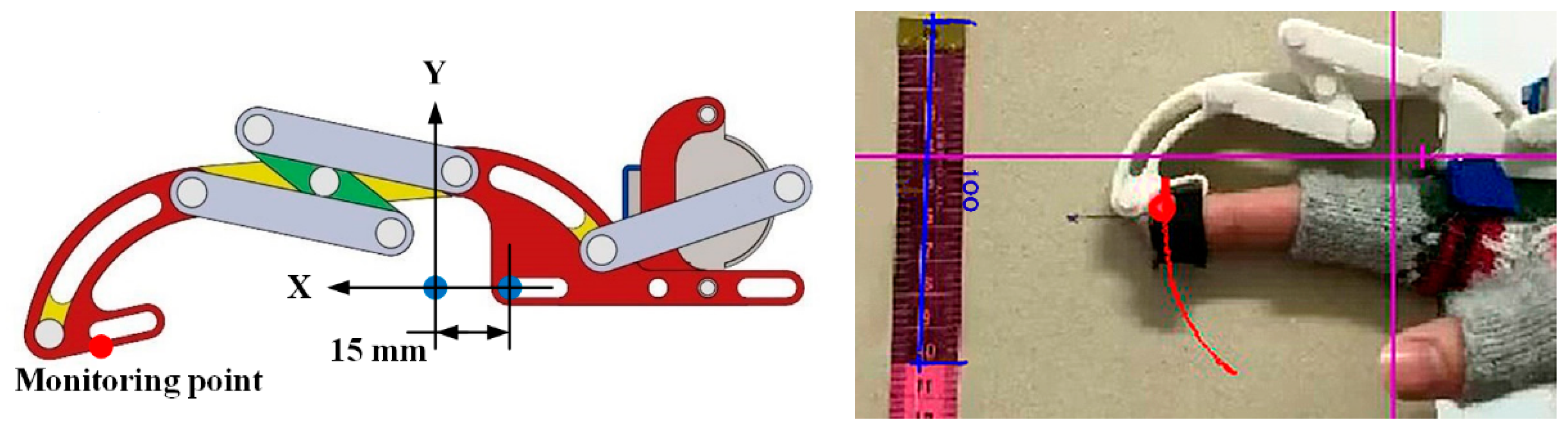
3.2. Motion Analysis
The red point shown on the robotic finger in Figure 4 was the measurement position used. The same point was used in Inventor Dynamic Simulation (simulated mechanics) and Tracker (real mechanics) to ensure the measurements made were compatible. The origin was set 15 mm to the left of the top of the metacarpophalangeal joint. The cycle for finger movement from straightening through flexing to straightening again, which was accomplished by one motor revolution, was set to be 16 s and 480 points were recorded for a complete cycle.
4. Discussion
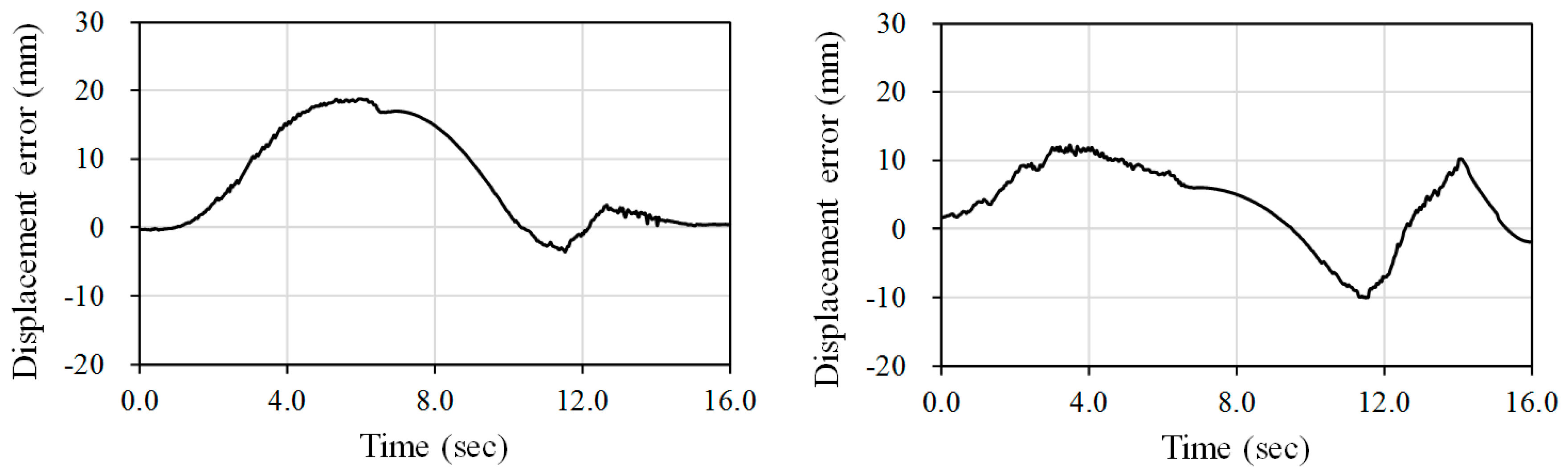
Figure 5 shows the simulated and measured displacements for the finger exoskeleton robot. Subtracting each simulated datum point from the real displacement point reveals the displacement errors for the x and y directions (see Figure 6). It can be seen that for x there is considerable error between 4 s and 8 s. This is due to the fact that the bolt in the link is too loose because the 3D oriented part has too much tolerance and the predicted path cannot be accurately followed. It can also be seen that in first half of the x-direction movement, displacement error is positive, while it is negative in the second half. This reveals that the displacement in the first half of the x movement is slower than in the simulation, and faster than the simulation in the second half. This error may be due to a large amount of friction forces between the 3D printed parts. To solve this problem, we will use computer numerical control (CNC) machines to make parts in the future. The same problem was evident in the y-direction. The roughness in the surfaces of the 3D printed parts also caused motion to be jerky and there were frequent disturbances of motion. The surfaces of parts machined from aluminum alloy will be smoother and in any case the contact surfaces will be polished.
For healthy people, typical torque values of joints are around 0.1~0.3 N-m [19,20]. Therefore, these values can be considered as the maximum joint torques to extend or flex for hand rehabilitation. Our current therapy device has a 30 N-mm input torque, which is suitable for slight stroke patients. For higher torques, because the torque is limited by the motor selected, it is possible to replace the 28BYJ-48 motor with other low-cost motors, such as the 12 volt 35BYJ-46 motor for a 78 N-mm input torque. The main advantage of our current therapy device is that it can be an in-home or portable solution for slight stoke rehabilitation, with a 5-volt mobile power supply or a USB interface.
In the simulation, the angle through which a fingertip could be rotated was from 173.2° to 72.0°, an ROM of 101.2°. However, in the experiments the angle achieved was from 170.4° to 126.2°, an ROM of 44.2°. Our goal is to make this range the same as that of a clutching fingertip. This can be done by increasing the length of the middle link of the N-shaped linkage. We will also attend to the problem of the connections between links. In our experiments we used plastic PLA but, as mentioned before, this material degrades over time. Future devices will be machined from aluminum alloy by CNC.
The proposed device can potentially be used for other medical or robotic applications [21]. In addition to post-stroke rehabilitation, this prototype could be functional for the rehabilitation of hand injuries. Since typical hand injuries affect only one finger, it could be used to improve the physical therapy after operations and help the patient regain range of motion of the finger [21]. By adequate design of the exoskeleton, it could also help prevent workplace injuries or help improve performance of different tasks.
Acknowledgments
We would like to thank the Ministry of Science and Technology, Taiwan, for support of the research work under grant no. MOST 104-2221-E-008-018-MY2 and MOST 104-2815-C-008-027-E.
Author Contributions
Tzu-Heng Hsu, Yen-Cheng Chiang, Wei-Tun Chan and Shih-Jui Chen conceived and designed the experiments; Tzu-Heng Hsu, Yen-Cheng Chiang, Wei-Tun Chan analyzed the data.
Conflicts of Interest
The authors declare no conflict of interest.
References
- Seshadri, S.; Wolf, P.A. Lifetime risk of stroke and dementia: Current concepts, and estimates from the Framingham study. Lancet Neurol. 2007, 6, 1106–1114. [Google Scholar] [CrossRef]
- Huang, H.C.; Siao, C.J.; Chen, Y.G. The rehabilitation system of finger joints. In Proceedings of the International Conference on Control Automation and Systems, Gwangju, South Korea, 20–23 October 2013; pp. 1055–1060. [Google Scholar]
- Krebs, H.I.; Hogan, N.; Aisen, M.L.; Volpe, B.T. Robot-aided neurorehabilitation. IEEE Trans. Rehabil. Eng. 1998, 6, 75–87. [Google Scholar] [CrossRef] [PubMed]
- Reinkensmeyer, D.J.; Kahn, L.E.; Averbuch, M.; McKenna-Cole, A.; Schmit, B.D.; Rymer, W.Z. Understanding and treating arm movement impairment after chronic brain injury, progress with the ARM guide. J. Rehabil. Res. Dev. 2000, 37, 653–662. [Google Scholar] [PubMed]
- Burgar, C.G.; Lum, P.S.; Shor, P.C.; Machiel Van Der Loos, H.F. Development of robots for rehabilitation therapy, the Palo Alto VA/Stanford’s experience. J. Rehabil. Res. Dev. 2000, 37, 663–673. [Google Scholar] [PubMed]
- Ito, S.; Kawasaki, H.; Ishigure, Y.; Natsume, M.; Mouri, T.; Nishimoto, Y. A design of fine motion assist equipment for disabled hand in robotic rehabilitation system. J. Frankl. Inst. 2011, 348, 79–89. [Google Scholar] [CrossRef]
- Li, J.; Wang, S.; Wang, J.; Zheng, R.; Zhang, Y.; Chen, Z. Development of a hand exoskeleton system for index finger rehabilitation. Chin. J. Mech. Eng. 2011, 25, 223–233. [Google Scholar] [CrossRef]
- Kyberd, P.J.; Light, C.; Chappell, P.H.; Nightingale, J.M.; Whatley, D.; Evans, M. The design of anthropomorphic prosthetic hands: A study of the Southampton Hand. Robotica 2001, 19, 593–600. [Google Scholar] [CrossRef]
- Pons, J.L.; Ceres, R.; Pfeiffer, F. Multifingered dextrous robotics hand design and control: A review. Robotica 1999, 17, 661–674. [Google Scholar] [CrossRef]
- Liu, Y.; Wang, H.; Li, B.; Zhou, W. The underactuation and motion-coupling in robotic fingers and two new 1-DOF motion-coupling anthropomorphic fingers. In Proceedings of the IEEE International Conference on Robotics and Biomimetics (ROBIO 2008), Bangkok, Thailand, 21–26 February 2009. [Google Scholar]
- Toda, H.; Kobayakawa, T.; Sankai, Y. A multi-link system control strategy based on biological reaching movement. Adv. Robot. 2006, 20, 661–679. [Google Scholar] [CrossRef]
- Heo, P.; Gu, M.G.; Lee, S.; Rhee, K.; Kim, J. Current hand exoskeleton technologies for rehabilitation and assistive engineering. Int. J. Precis. Eng. Manuf. 2012, 13, 807–824. [Google Scholar] [CrossRef]
- Allotta, B.; Conti, R.; Governi, L.; Meli, E.; Ridolfi, A.; Volpe, Y. Development and experimental testing of a portable hand exoskeleton. In Proceedings of the IEEE International Conference on Intelligent Robots and Systems (IROS), Hamburg, Germany, 28 September–2 October 2015. [Google Scholar]
- Polygerinos, P.; Lyne, S.; Wang, Z.; Nicolini, L.F.; Mosadegh, B.; Whitesides, G.M.; Walsh, C.J. Towards a soft pneumatic glove for hand rehabilitation. In Proceedings of the International Conference on Intelligent Robots and Systems (IROS), IEEE/RSJ, Tokyo, Japan, 3–7 November 2013. [Google Scholar]
- Pfeiffer, F. Grasping with hydraulic fingers—An example of mechatronics. IEEE/ASME Trans. Mechatron. 1996, 1, 158–167. [Google Scholar] [CrossRef]
- Zardoshti-Kermani, M.; Wheeler, B.C.; Badie, K.; Hashemi, R.M. EMG feature evaluation for movement control of upper extremity prostheses. IEEE Trans. Rehabil. Eng. 1995, 3, 324–333. [Google Scholar] [CrossRef]
- Wolpaw, J.R.; Birbaumer, N.; McFarland, D.J.; Pfurtscheller, G.; Vaughan, T.M. Brain–computer interfaces for communication and control. Clin. Neurophysiol. 2002, 113, 767–791. [Google Scholar] [CrossRef]
- Pires, J.N.; Bugmann, G. Robot-by-voice: Experiments on commanding an industrial robot using the human voice. Ind. Robot. 2005, 32, 505–511. [Google Scholar] [CrossRef]
- Wang, J.; Li, J.; Zhang, Y.; Wan, S. Design of an exoskeleton for index finger rehabilitation. In Proceedings of the IEEE EMBS conference, Minneapolis, MN, USA, 2–6 September 2009. [Google Scholar]
- Kawasaki, H.; Kimura, H.; Nishimoto, Y.; Hayashi, H.; Sakaeda, H. Hand rehabilitation support system based on self-motion control, with a clinical case report. In Proceedings of the Automation Congress, Budapest, Hungary, 24–26 July 2006. [Google Scholar]
- Wege, A.; Hommel, G.; Kondak, K. Development and control of a hand exoskeleton for rehabilitation of hand injuries. In Proceedings of the International Conference on Intelligent Robots and Systems, Edmonton, AB, Canada, 2–6 August 2005. [Google Scholar]
Figure 1.
Design of the finger exoskeleton robot that allows the finger to curl from (a) extended to (d) flexed.
Figure 1.
Design of the finger exoskeleton robot that allows the finger to curl from (a) extended to (d) flexed.
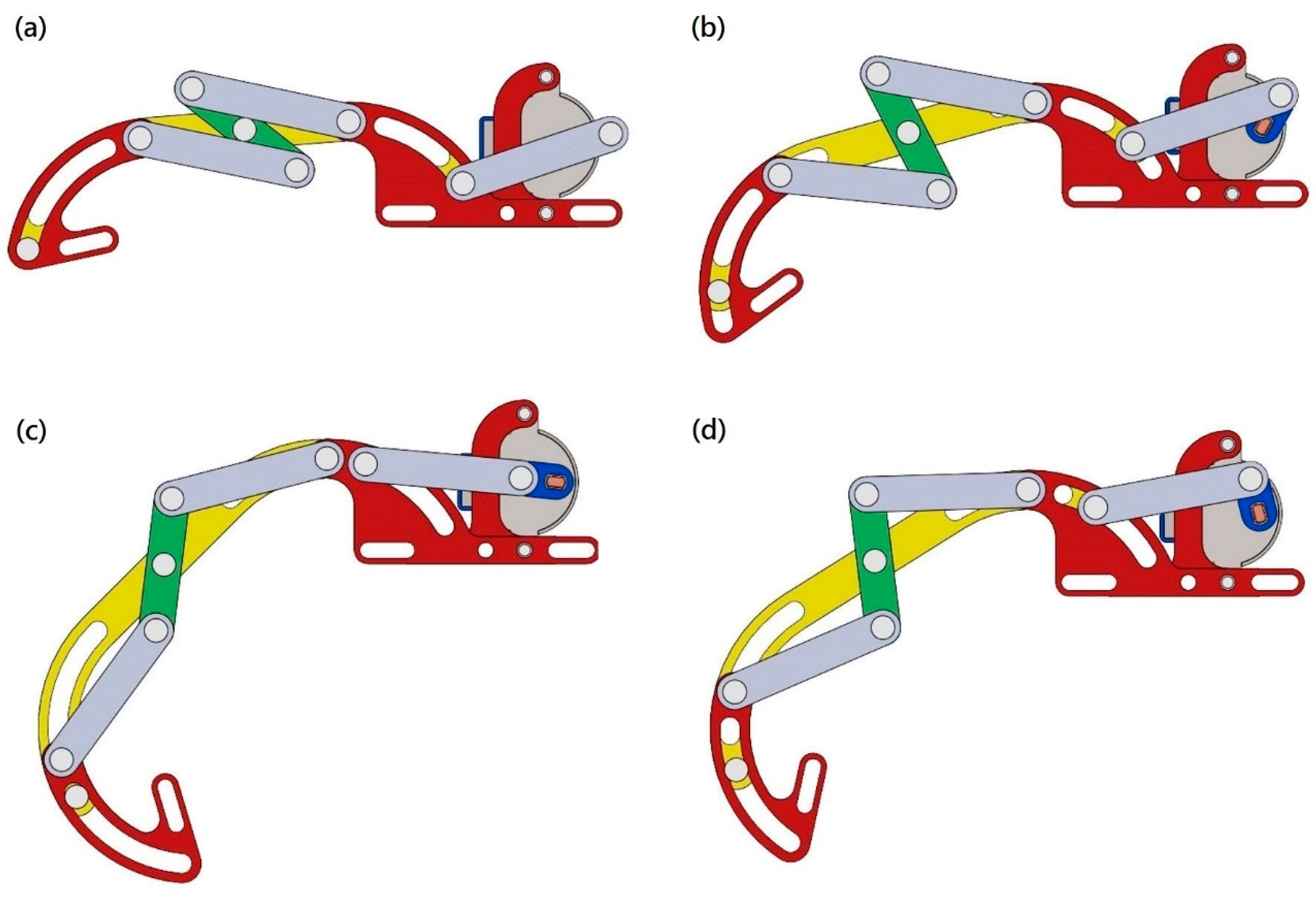
Figure 2.
Simulated results: the first principal stress (a) and the third principal stress (b).

Figure 3.
Experimental setup.
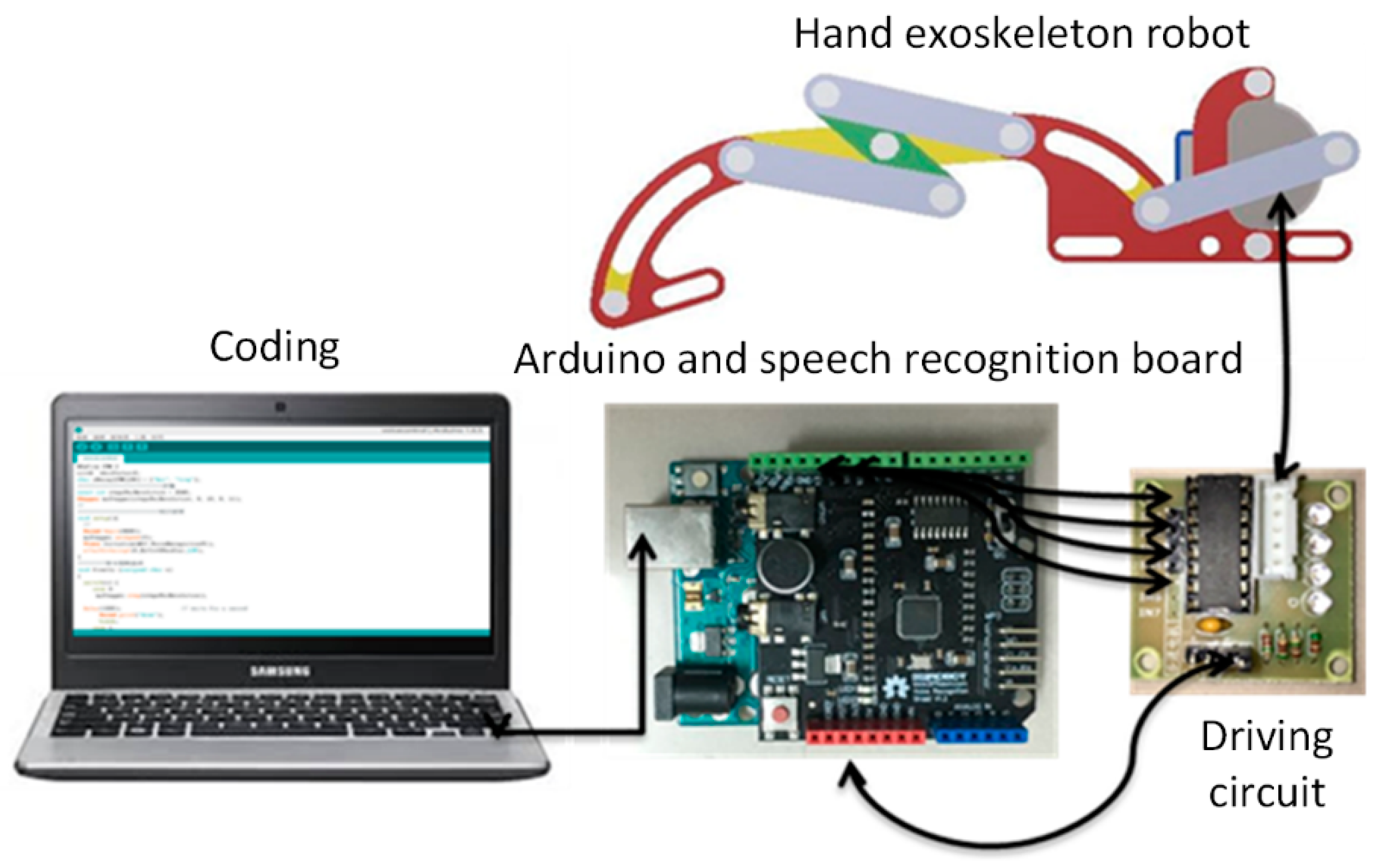
Figure 4.
Definition of the monitoring point and original point for the simulation (left) and the real displacements of the exoskeleton robot fingertip. The blue line in the photo represents 100 mm, and the red line refers to the trajectory of the fingertip (right).
Figure 4.
Definition of the monitoring point and original point for the simulation (left) and the real displacements of the exoskeleton robot fingertip. The blue line in the photo represents 100 mm, and the red line refers to the trajectory of the fingertip (right).

Figure 5.
Simulated and measured displacements for x-direction (left) and y-direction (right).
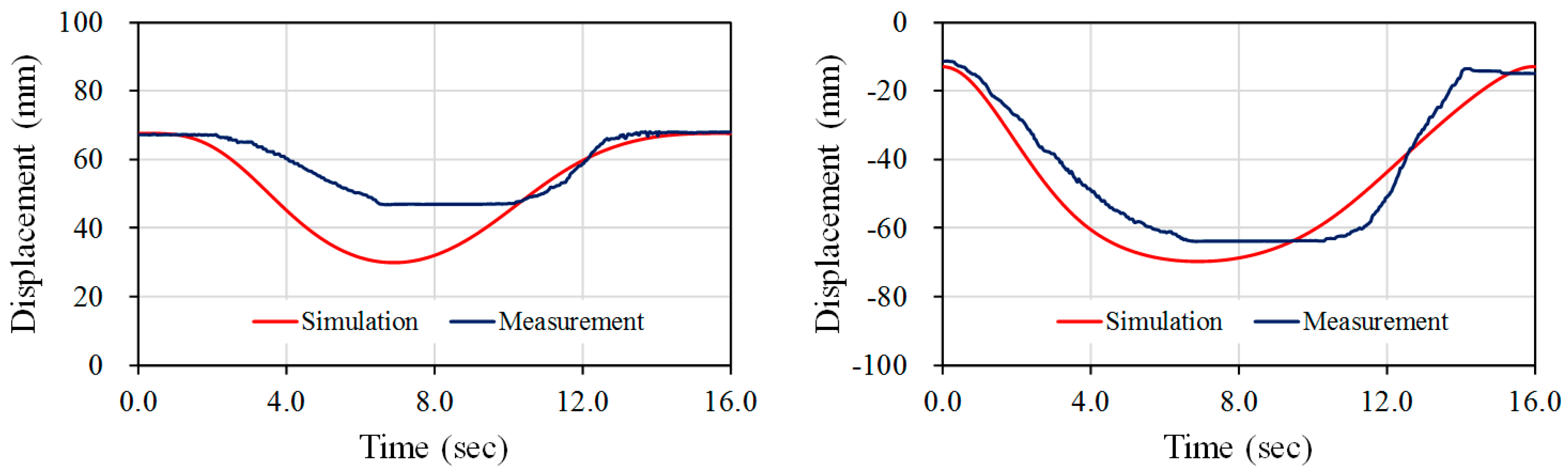
Figure 6.
Displacement errors for x-direction (left) and y-direction (right).

Table 1.
Simulated results.
| Value | First Principal Stress | Third Principal Stress | Safety Factor | Displacement |
|---|---|---|---|---|
| Maximum | 4.68 MPa | 1.27 MPa | 15 | 0.02 mm |
| Minimum | −1.32 MPa | −4.41 MPa | 3.07 | 0 mm |
© 2017 by the authors. Licensee MDPI, Basel, Switzerland. This article is an open access article distributed under the terms and conditions of the Creative Commons Attribution (CC BY) license (http://creativecommons.org/licenses/by/4.0/).
Share and Cite
MDPI and ACS Style
Hsu, T.-H.; Chiang, Y.-C.; Chan, W.-T.; Chen, S.-J. A Finger Exoskeleton Robot for Finger Movement Rehabilitation. Inventions 2017, 2, 12. https://doi.org/10.3390/inventions2030012
AMA Style
Hsu T-H, Chiang Y-C, Chan W-T, Chen S-J. A Finger Exoskeleton Robot for Finger Movement Rehabilitation. Inventions. 2017; 2(3):12. https://doi.org/10.3390/inventions2030012
Chicago/Turabian StyleHsu, Tzu-Heng, Yen-Cheng Chiang, Wei-Tun Chan, and Shih-Jui Chen. 2017. "A Finger Exoskeleton Robot for Finger Movement Rehabilitation" Inventions 2, no. 3: 12. https://doi.org/10.3390/inventions2030012