Article

Frequency Transient Suppression in Hybrid Electric Ship Power Systems: A Model Predictive Control Strategy for Converter Control with Energy Storage

by
Viknash Shagar
*,
Shantha Gamini Jayasinghe
and
Hossein Enshaei
Australian Maritime College, University of Tasmania, Launceston, Tasmania 7250, Australia
*
Author to whom correspondence should be addressed.
Inventions 2018, 3(1), 13; https://doi.org/10.3390/inventions3010013
Submission received: 26 December 2017 / Revised: 20 February 2018 / Accepted: 27 February 2018 / Published: 1 March 2018

Abstract

:
This paper aims to understand how the common phenomenon of fluctuations in propulsion and service load demand contribute to frequency transients in hybrid electric ship power systems. These fluctuations arise mainly due to changes in sea conditions resulting in significant variations in the propulsion load demand of ships. This leads to poor power quality for the power system that can potentially cause hazardous conditions such as blackout on board the ship. Effects of these fluctuations are analysed using a hybrid electric ship power system model and a proposed Model Predictive Control (MPC) strategy to prevent propagation of transients from the propellers into the shipboard power system. A battery energy storage system, which is directly connected to the DC-link of the frequency converter, is used as the smoothing element. Case studies that involve propulsion and service load changes have been carried out to investigate the efficacy of the proposed solution. Simulation results show that the proposed solution with energy storage and MPC is able to contain frequency transients in the shipboard power system within the permissible levels stipulated by the relevant power quality standards. These findings will help ship builders and operators to consider using battery energy storage systems controlled by advanced control techniques such as MPC to improve the power quality on board ships.

1. Introduction

The transportation industry has experienced many technological advancements over the years. One of the key developments is electrification in the form of electric traction or electric propulsion. In view of recent legislation involving the creation of Emission Control Areas (ECAs) [1], ships with electric propulsion have become more of a reality with more cruise ships, ice breakers and various types of service vessels adopting this technology [2]. However, hybrid propulsion is a convenient waypoint between traditional mechanical propulsion and fully-electric propulsion as it combines the two, thereby reducing the need for a complete revamp of the propulsion system in very large ships such as container vessels. In these ships, propulsion load is the most challenging type of load as it forms the largest proportion of the total load in the electrical system. The propulsion load could vary within a wide range in a matter of seconds, which could result in transient conditions in the hybrid shipboard power system that can include overheating due to high inrush currents in addition to voltage and frequency fluctuations [3,4]. The load busbar frequency plays an important part in maintaining the power quality due to the relationship between the electrical torque by a synchronous generator and generator speed deviation following a disturbance to the power system [5]. Failure or malfunction of crucial equipment that relies on a high level of power quality at sea such as navigation instruments could result in misinformation and power outages on board, leading to potentially disastrous consequences for lives and property at sea for seaborne vessels [6,7]. Energy storage is effective at reducing such transients due to its ability to exchange active power as required using appropriate control systems resulting in adjustments of the frequency level. This provides a means of reducing frequency transients by controlling power flow from energy storage systems by means of suitable control techniques.
The hybrid electrical shipboard power system considered in this study is shown in Figure 1, which contains a Battery Energy Storage System (BESS). The advantages of using a battery as a source of energy storage in power systems is well known. In addition to the reserve energy capacity that it provides, there is considerable literature recommending the use of a BESS to effectively deal with frequency transients, especially in standalone power systems such as terrestrial microgrids, major power grids and in shipboard power systems [8,9,10,11]. The BESS integrated with the power system has to be fast in its response to changes in the power system and also have sufficient capacity to bring the state of the power system back to normal operating conditions. Therefore, the BESS control strategy has to be robust in order to act effectively in view of the constantly evolving load conditions of the hybrid ship. The extreme environmental conditions experienced by ships at sea such as sea waves should be taken into account when designing a control strategy for the BESS.
In the system shown in Figure 1, the BESS is directly connected to the DC-link of the frequency converter as opposed to the majority of literature, which uses a DC-DC converter to interface the battery to the DC-link [9,10,12]. The absence of this interfacing converter reduces the complexity of the energy storage system while at the same time retaining control of the battery current.
Bi-directional power flow of the frequency converter is an important feature in the hybrid electric ship power system due to the possibility of a battery being charged and discharged in two directions, which could be from the main engine or the auxiliary engine. The main engine supplies mechanical power to the propeller and/or electrical power through the shaft generator to the main busbar of the ship’s power system. The auxiliary engine, on the other hand, can supply electrical power to the busbar or further downstream to the shaft machine to be converted to mechanical power if necessary. As these power flows occur across the energy storage system, they can either charge or discharge the battery as required.
Conventional PI control and droop control for the converters have been used in many studies to reduce frequency deviations and improve power tracking for load change studies [13,14,15,16]. These control methods have been found to be slower acting and less efficient in rapidly changing loading conditions [17]. Advanced control strategies such as MPC and adaptive control have also been more recently explored in various research studies as more effective control techniques to reduce frequency transients [18,19,20]. These strategies, while reacting faster to changes in system operation as compared to feedback control techniques such as PI, have the added benefit of reducing charging and discharging current for batteries and improving the power tracking capabilities of the energy storage system by reducing tie power deviations. Furthermore, they are found to be suitable for highly non-linear problems with multiple constraints as in applications such as isolated power systems. However, most of the work in this area has not targeted the growing area of hybrid electric ship power systems, which presents a unique configuration involving interconnections of both mechanical and electrical components. Furthermore, though the results in the vast majority of work in this area show that the transient effects on electrical parameters have been reduced through the use of various control methods, they still exist to some extent, especially in hybrid electric ships mainly due to the above-mentioned unique configuration. A comprehensive background review of energy storage as a potential solution to load changes in hybrid ships has been reported in [21]. In contrast to the published work, an important objective of this work is to give a clear picture of the modelling of a hybrid propulsion shipboard power system with battery energy storage capability that is controlled by an MPC strategy. The effects that varying mechanical propulsion loads and electrical service loads in different combinations can have on the mechanical aspect of generator speeds and the electrical aspect of load busbar frequency have not been studied in sufficient detail for vessels that utilize hybrid propulsion. The aim of this study is to gain a clearer understanding of the mechanical and electrical dynamics of this complex power system. The extent to which the electrical frequency deviations are evident in terms of the observed transient magnitudes and settling times of the transients due to various loading conditions will also be investigated in this paper.
The rest of the paper is organized as follows. Section 2 presents the modelling aspects of the hybrid electric ship power system and its various modes of operation. Section 3 introduces the Model Predictive Control (MPC) strategy and explains how it has been modified and adopted in the hybrid shipboard power system. Section 4 explains the load change scenarios simulated using the developed hybrid shipboard power system model under different operating conditions and the results obtained. An analysis of the results will follow in Section 5. Finally, Section 6 concludes the study.

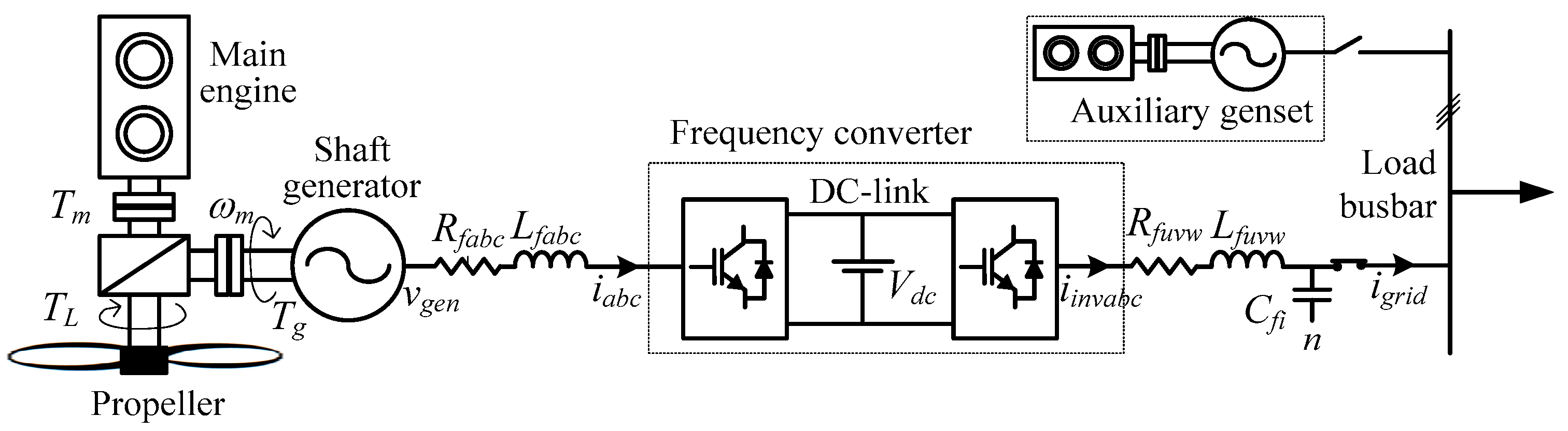
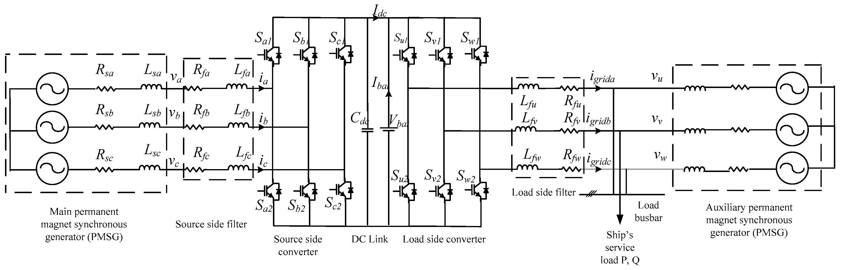
2. Hybrid Shipboard Power System Modelling and Operation

The modelling of the hybrid power system closely follows the schematic shown in Figure 1. MATLAB-Simulink® software has been used to run the simulations. The five major components to be modelled are the shaft generator, auxiliary engine-generator set (genset), BESS, source side converter and grid side converter. It is to be noted that the source side converter is located near the shaft machine, while the load side converter is located next to the service loads and the load busbar as shown in Figure 1. In Figure 1, both of these converters are jointly called the frequency converter, as it converts the variable voltage-variable frequency output of the shaft generator to be connected to the constant voltage-constant frequency ship power system.
The main engine torque value has been set to the optimum value based on the specific fuel oil consumption versus load characteristics of the main engine [22]. The advantage of constant speed operation is two-fold. Firstly, the speed can be set at the most efficient point for the main engine. This results in fuel savings. Additional torque can be supplied by the auxiliary generator or the battery energy storage. Secondly, since the output torque of the engine is not changing, the transients passed along by the main engine to the rest of the system are reduced. This is highly desirable as lesser speed transients mean that the electrical frequency transients due to the main engine operation can be eliminated, thus reducing the overall frequency transients as seen in the electrical system. The propeller dynamics have been ignored in this study, although the propulsion loading profile is represented as approaching a step load profile. A step load profile is generally considered to be the worst case loading due to the rapid rate of load increase and decrease. Therefore, loading profiles similar to a step load profile of the propulsion load are used in this study in order to understand the transient effects that these have on the system frequency. Service loads have been taken to be resistive and inductive in nature, and portions of this load will be switched in and out of the system to examine their effects on the resulting transients. The effects of varying both the propulsion and service loads will be explored in this study.
The modelling of the main and auxiliary engines, as well as the shaft generator and the auxiliary generator remains the same as in a previous work done in [21] by the authors. The modelling of the Permanent Magnet Synchronous Generator (PMSG) with the IEEE Type 1 excitation system is well known and has been used widely in various other studies [7,22,23,24]. However, it is important to note that in this case, the shaft generator can also act as a motor. Thus, this device is also called the shaft machine. When the main engine is supplying power to the load busbar to feed the ship’s service loads, the shaft machine is acting as a generator. However, when the auxiliary generator and/or the battery is supplying power to the propulsion load, then the shaft machine carries out motor operation.
The system parameters of the model are given in Table 1. It is worth noting that the set point capacity of the main engine is fixed at 85% of its maximum capacity assuming that it is the point of maximum efficiency of the engine. The capacity of the auxiliary generator is kept at 20% of that of the main generator.
Lithium ion batteries have been used in this study. They have been used commercially for a long time, and their high efficiency and high energy and volume density coupled with low cost per usable kWh per cycle have made them suitable for use in energy storage systems. These batteries have been used in high power applications involving pulse loads, which can be considered similar to enviro Nmental conditions such as sea waves that hybrid ships can potentially face in high seas that demand a quick response from the shipboard power system and its associated energy storage [25,26,27]. Lithium ion batteries have also been successfully integrated in the energy storage system of power systems that use bidirectional converters and utilize MPC to control these converters [27,28]. The lithium ion battery model used in this study has been adopted from models available in the MATLAB-Simulink software. The reader is encouraged to refer to [29,30] for the mathematical representation of the battery including the charging and discharging rate formulation. The specification of the battery used in the model is shown in Table 2.

3. Proposed MPC Strategy

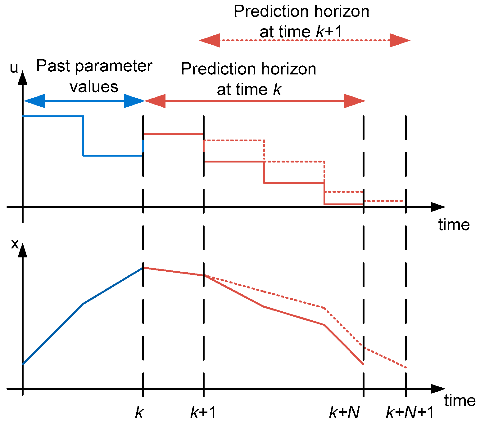
3.1. The MPC Concept

The general algorithm used for the MPC strategy will be introduced and explained below. This will be aligned with the modification and application of the MPC strategy to the hybrid ship power system in Section 3.2. Note that u(k + i/k) and x(k + i/k) refer to the input and state vectors at time k + i, which are predicted at time k. x(k + i), and will then evolve as per a prediction model.
The optimization stage involves minimization of a cost function J(k) that includes relevant input parameters, u(k), and state parameters, x(k), of the system under consideration in order to maximize performance. Constraints on the input, u(k), can also be imposed as appropriate for the application to be solved simultaneously with the cost function.
The optimal input sequence of u(k), u*(k) would be the one that minimizes J(k). MPC utilizes the receding horizon implementation technique. Receding horizon implementation means that only the first element of u*(k) is fed to the plant model, and following that, the process of minimizing the predicted cost is then repeated again in the next time instant for the next set of u*(k) to be determined. This process of optimization is known as online optimization. The length of the prediction horizon remains the same at each time instant giving rise to the receding horizon concept portrayed in Figure 2. The measurement of the current state is required to compute u*(k), and this element of feedback that exists in the MPC law increases the robustness of this control strategy [31,32]. One of the main advantages of the MPC strategy is that it can be applied to a wide range of plant models. These can be linear or non-linear. The prediction model could be deterministic, stochastic or fuzzy in nature and discrete or continuous. Discrete time prediction models perform optimization periodically at times t (=kT), and at each time instant k, T has to be sufficiently large to take into account the computation time at each iteration. However, the sampling interval, Tsamp, could be a fraction of T if the optimal input sequence from the previous computation is to be used for further analysis. Continuous time prediction models are only used when the plant dynamics do not have a closed form discrete time representation such as in the case of non-linear plant models, and the previous optimal trajectory is accessible when the controller is computing the current optimal trajectory. In deterministic prediction models, the output of the prediction model is determined by fully-defined parameter values and initial conditions. Stochastic prediction models have inherent randomness that gives a variety of outputs for each run given the same set of parameters and initial condition values. Fuzzy prediction models rely on creating fuzzy rules based on the clustering effect of the existing data to make predictions of the future trajectory of plant operation [33,34].
This study looks into improving the MPC concept and adopting it into the hybrid shipboard power system. As mentioned in Section 1, bidirectional converters are essential for controlling power flow between the battery and the loads, as well as the main and auxiliary power sources. As the converters perform rectifier and inverter operations, proper switching of the power electronic elements is essential to ensure expected power flow that is in line with power supply and demand in the system. This can be achieved if certain key control objectives are met when predicting the switching sequence in the converters ahead of time. As mentioned in Section 2, regulating the speed of the main generator is the control objective for the source side converter. To ensure high energy sufficiency and preventing overheating and flux weakening, current flow should not exceed the desired value that is just sufficient to meet the power requirements. Finally, the predicted amount of active and reactive power flow to the electrical load side should be as close as possible to the actual power flow to avoid additional stress to the system, which can result in worse transient conditions. Section 3.2 will look into how the implementation of the MPC concept into the converters can optimize the above-mentioned objectives.

3.2. MPC Implementation in the Hybrid Shipboard Power System

An MPC with a short prediction horizon has been chosen as the control strategy for converter control in the hybrid shipboard power system operation due to its advantages of rapid response and ease of implementation even in cases of non-linearity and multiple constraint optimization. The literature suggests that it is less complex to implement compared to conventional converter control techniques such as Voltage Control-based Pulse Width Modulation (PWM) with better reference tracking capabilities [35,36,37]. The major disadvantage of using MPC would be the high computational burden in the algorithm. However, with the rapidly increasing processing power of microprocessors, this is unlikely to be a huge deterrent and is one that is common to most advanced control techniques [11]. MPC has been applied to two different components in the converter control system. They are the source side converter and the grid (load) side converter. A schematic diagram of the proposed converters in the electrical system of the hybrid ship is shown in Figure 3, and their operation is described below.

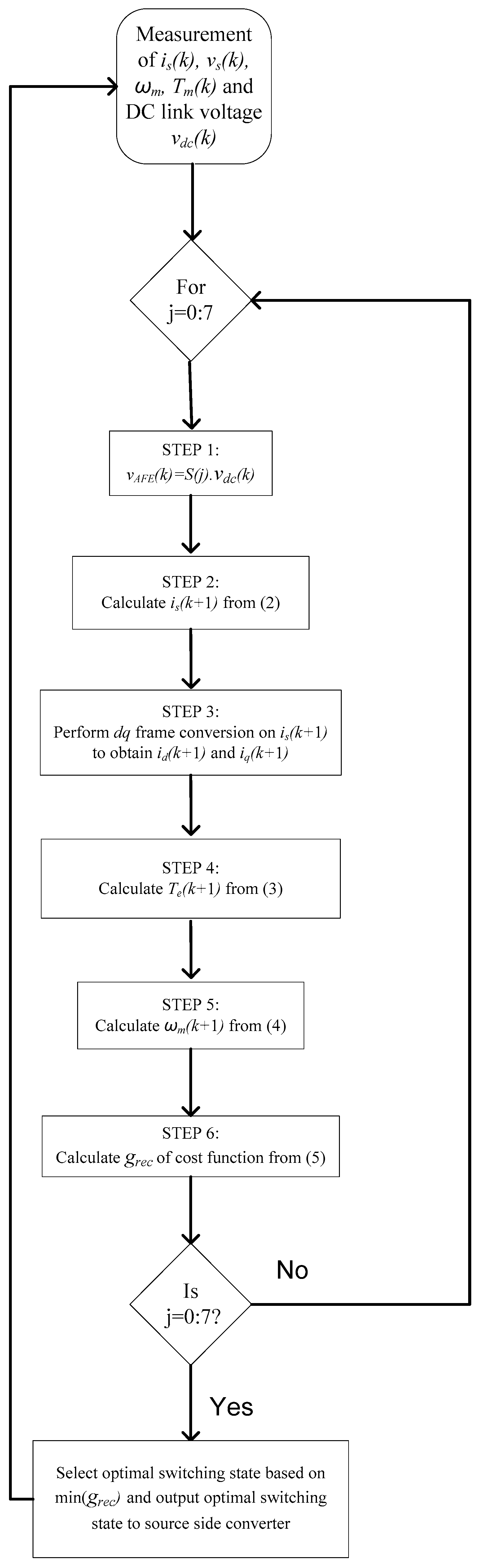
3.2.1. Source Side Converter Modelling with the MPC Strategy

This converter is directly connected to the shaft machine AC supply via series inductors and resistors that act as filters. It has the capability of bidirectional operation depending on the direction of power flow from the main generator or from the auxiliary generator. It consists of six Insulated Gate Bipolar Transistor (IGBT) diode switches as shown in Figure 3. The switching configuration is such that no two switches in the same branch will be on or off simultaneously in order to prevent short circuiting in the system. As each switch in each phase can have two states of either being on or off, the three signals from the three phases would produce eight possible switching states that can be represented by a switching function vector, S . This would result in eight different voltage space vectors. Using Kirchoff’s voltage law, the source side converter’s space vector can be found. The input current dynamics can then be derived, and since the MPC controller works in a discrete time domain, this is written in discrete time form as in Equation (1):
d i s d t = i s ( k + 1 ) i s ( k ) T s
where it is to be noted that i s is the source side converter input current vector, k is the sampling instant and T s is the sampling time. From Equation (1), the current at the ( k + 1 ) th time instant can be predicted as:
i s ( k + 1 ) = ( 1 R s T s L s ) i s ( k ) + T s L s ( v s ( k ) v A F E ( k ) )
where v s is the generated three-phase voltage vector, v A F E is the converter output voltage and R s and L s are the total resistance and inductance of the PMSG and filter. The future value current, i s ( k + 1 ) , is predicted for each of the eight switching states. Each of these current values is then converted into the dq frame. This is used to predict the future generator electromagnetic torque, T e ( k + 1 ) , which in turn is used to compute the future predicted mechanical angular speed of the generator, ω m p = ω m ( k + 1 ) , as per Equations (3) and (4):
T e ( k + 1 ) = 1.5 p ψ i q ( k + 1 )
ω m p = ω m ( k ) + T s J ( T m T e ( k + 1 ) )
Note that T m is the mechanical torque applied on the generator, i q is the q axis current, p is the number of poles and ψ is the PMSG flux. The values ω m p and i s ( k + 1 ) are then used in the cost function, g r e c , Equation (5), to deduce the switching state that gives the minimum value for the function.
g r e c = | ω * ω p | + K · | i d r e f i d ( k + 1 ) |
where ω * is the reference speed, i d r e f is the reference d-axis current and i d ( k + 1 ) is the predicted future value d-axis current. The speed variation is to be kept as close to zero as possible due to the aforementioned strategy to keep the output torque of the main generator constant at its most optimal level. The constant, K, has been added to further reduce the d axis current in the generator and thus prevent flux weakening and overheating effects in the generator. A flowchart of the MPC control algorithm used for the source side converter is shown in Figure 4.

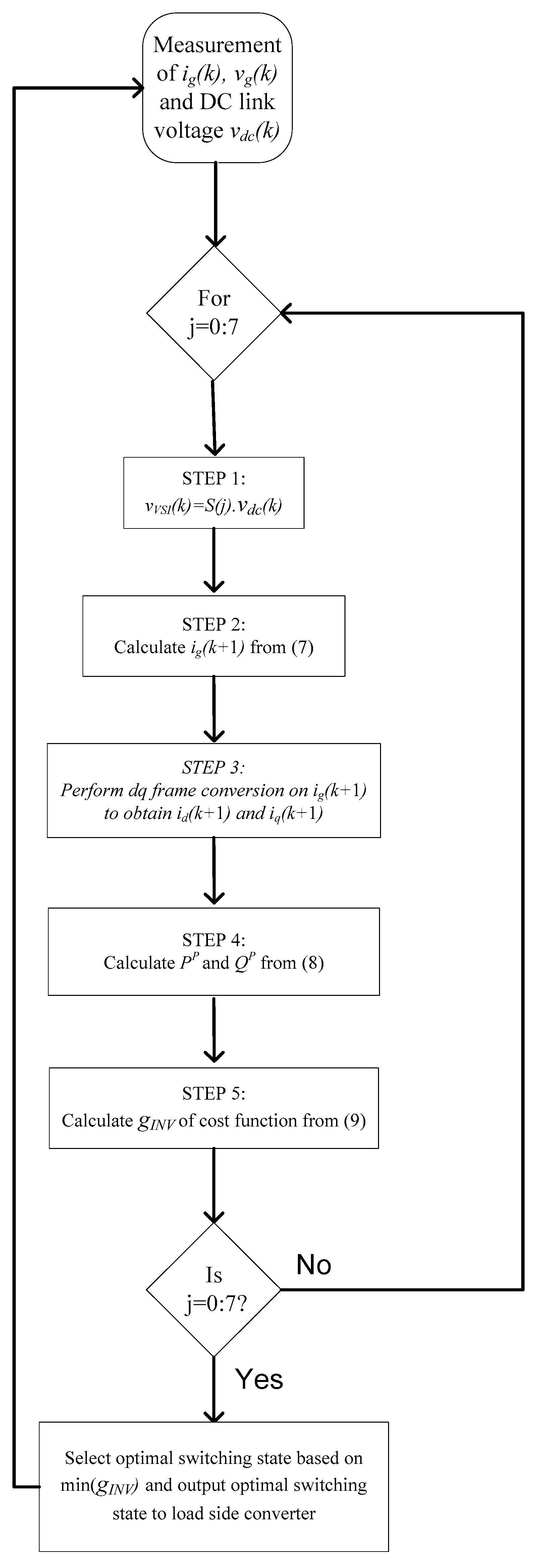
3.2.2. Grid (Load) Side Converter Modelling with MPC Strategy

This converter connects the BESS to the load busbar through filters. The load busbar serves the service loads for ships and also receives power from the auxiliary generator and main generator if needed to supply service or propulsion load increases. Therefore, this converter has bidirectional operation where it can act as a rectifier or an inverter depending on the direction of power flow. The objective of the grid side converter control is to limit the active and reactive power needed by the loads to the required levels. The MPC concept achieves this objective in an efficient manner using a predictive control strategy. The switch operation of this converter is similar to the source side converter. The mathematical relation between the converter input voltage, v V S I , and the three phase load busbar voltage derived from Kirchhoff’s law applied to the output side of the converter is explained in [11]. The input current dynamics to the converter is as follows:
d i g d t = R g i g L g v g L g + v V S I L g
where i g , v g and v V S I are the load busbar current, voltage and inverter input voltage vectors, respectively. The inductive and resistive filter components are denoted by L g and R g . Equation (6) can then be discretized to predict the grid current at the (k + 1)-th time instant in the proposed MPC strategy as shown in Equation (7):
i g ( k + 1 ) = ( 1 R g T g L g ) i g ( k ) + T s L g ( v V S I ( k ) v g ( k ) )
From Equation (7), the apparent power and hence the real and active power prediction for the converter at the next time instant, S ( k + 1 ) , can be calculated as in Equation (8):
S P ( k + 1 ) = P P ( k + 1 ) + j Q P ( k + 1 )     = [ R e ( v ( k ) ) · R e ( i ( k + 1 ) ) + I m ( v ( k ) · I m ( i ( k + 1 ) + j [ I m ( v ( k ) )     · R e ( i ( k + 1 ) ) R e ( v ( k ) ) · I m ( i ( k + 1 ) ) ]
The difference between the reference active and reactive power denoted by P* and Q*, and the predicted values for the (k + 1)-th time instant as denoted by PP and QP, is then calculated for all the switching states in the cost function as shown in Equation (9). The P* value is set depending on the variation of the measured speed of the auxiliary generator, ωmeasured from the reference speed ω* as stated in Table 1. P* can also be considered to be the power that the battery supplies to the system and is calculated as in Equation (10). Q* is zero in all cases. The switching state that gives the minimum g I N V value for this cost function is then chosen to be implemented in the next time instant. It is worth noting that the same control strategy for the converters is employed when the battery is not in operation. A flowchart illustrating the MPC control algorithm used for the grid (load) side converter is displayed in Figure 5.
g I N V = | Q * Q P | 2 + | P * P P | 2
P * = 4000 ( ω * ω m e a s u r e d ) 1500 d ω m e a s u r e d d t

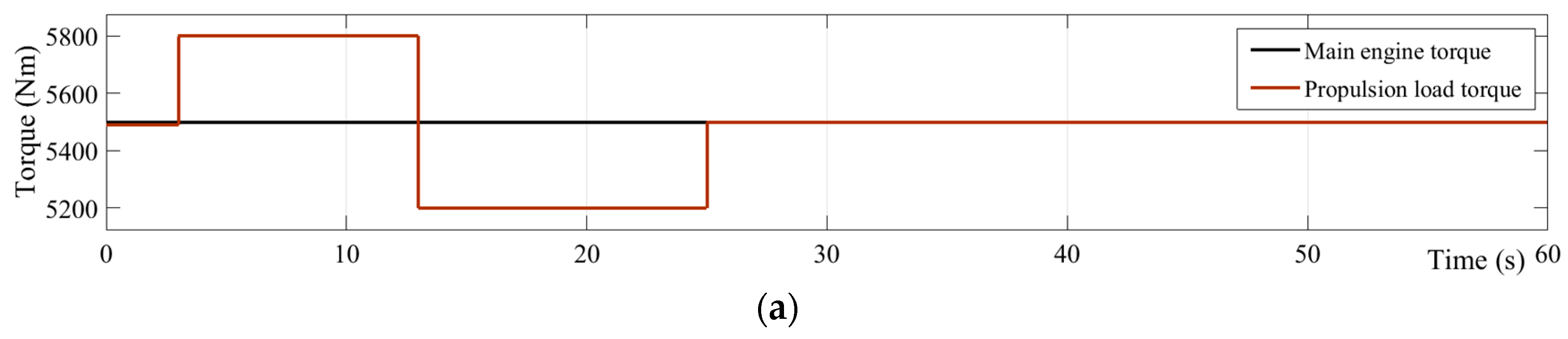
4. Simulation Results

In order to assess the performance of the proposed solution in reducing the propagation of transients from the propulsion load to the electrical load busbar and frequency transients caused by service load changes, step changes are applied to the loads as shown in Figure 6a,b. These load changes and corresponding simulations are grouped into four scenarios, namely 1a, 1b, 2a and 2b, for the clarity of the discussion. Simulation results of these scenarios are combined and plotted together in corresponding waveforms in Figure 6 for the simplicity of the comparison. Scenarios 1a,b are without BESS, while Scenarios 2a,b use a BESS. Propulsion load changes have been applied in Scenarios 1a and 2a as shown in Figure 6a during the 0–30-s period. In order to keep the main engine speed constant as explained in Section 2, it is set to deliver a constant torque of 5500 Nm, which is termed the ‘main generator set point torque’. Service load changes applied for Scenarios 1b and 2b are shown in Figure 6b during the 30–60-s period. The steady state is considered to be achieved when the parameter being considered is within 2% of the steady state value. These variations would be ±1.36 rad/s and ±1 Hz for the main generator speed and load busbar frequency, respectively, based on the reference values in Table 1. The International Electrotechnical Commission (IEC) has recommended ranges for frequency excursions for both permanent and temporary conditions. As transient conditions are considered temporary in nature, the maximum allowable variation of the frequency amplitude is 10% with a maximum settling time period of 5 s [21].
In order to focus the study only on load changes that occur during steady state operation of the system, any initial speed transients of the engines due to engine start up dynamics are not considered. In Scenarios 1a and 2a, propulsion load is increased to 5800 Nm, reduced to 5200 Nm and then brought back to 5500 Nm at 3 s, 13 s and 25 s, respectively, while service load remains constant at 50 kW. A Resistive-Inductive (RL) load is chosen for the service with 5 kVar reactive power to reflect commonly-used loads in ship power systems. The corresponding variations of the shaft generator speed and load busbar frequency are shown in Figure 6c,d, respectively. The shaft generator speed variations for both scenarios are the same, and thus, the two traces coincide. Nevertheless, the load busbar frequency has significant differences in the two scenarios, and they are marked as ‘without battery’ and ‘with battery’ for Scenarios 1a and 2a, respectively. The upper limit and lower limit for frequency transients are also marked in Figure 6d to identify unacceptable scenarios. The DC-link voltage is indirectly controlled by the converter controllers in Scenario 1a, and the corresponding variations under load change scenarios are shown in Figure 6e by the trace marked as ‘without battery’. In the same figure, DC-link voltage variation for Scenario 2a is marked as ‘with battery’ where the BESS governs the voltage instead of converters controlling it. The corresponding variations in inverter power, auxiliary engine power and service load are shown in Figure 6f.
In Scenarios 1b and 2b, service load is increased from 50 to 80 kW and then brought back to 50 kW at 35 s and 45 s, respectively, while propulsion load remains constant at 5500 Nm. Similar to the above description, the corresponding variations in the shaft generator speed and load busbar frequency are shown in Figure 6c,d, respectively. The DC-link voltage is shown in Figure 6e. The corresponding variations in inverter power, auxiliary engine power and service load are shown in Figure 6g.

5. Discussion of Results

The main objective of this study in using energy storage with MPC control to reduce speed and frequency transients is two-fold. Firstly, the propagation of transients from the main engine to the electrical load busbar due to changing propulsion load conditions is to be reduced. Secondly, the overall transients in the system are to be decreased. Excessive frequency transients indicate poor power quality and can affect the operation of other electrical equipment that draw power from the load busbar. Therefore, it is crucial that any load changes that occur at the mechanical part of the system that involves propulsion or the electrical part of the system supplying the service loads result in minimal speed fluctuation to the auxiliary generator speed. From the above discussion, it becomes clear that speed fluctuations at the auxiliary generators are more crucial as they have more implications for electrical power quality for other electrical components of the hybrid shipboard power system as compared to the main generator, which only serves the propulsion load. Moreover, while propellers and connecting shafts do suffer from fatigue over time due to speed fluctuations, electrical components malfunction much more quickly and are more difficult to detect especially when sensitive technology such as navigation equipment is involved.
The scenario studies and results from the Section 4 are structured in such a way so as to clearly highlight the effects of changing propulsion and service loading conditions separately on the main and auxiliary generator speeds and observing how these parameters are affected by adding battery energy storage. The load changes are applied as step changes to simulate the most challenging load changes. This would be the most appropriate type of loading profile encountered due to the fact that the waves and wind conditions that a ship experiences in rough weather are unpredictable and have a high impact on the load level of a ship in a short period of time. Service load changes can also be considered as step load changes as the resistive and inductive loads are switched in through a circuit breaker in the system, while they are directly being fed by the load busbar, thereby creating the highest possible impact.
The results in general indicate that speed and frequency settling times remain at or within 5 s for all of the cases. However, it is clear from the frequency plots that the rate of recovery of the system is much slower with battery energy storage. In Scenario 1b where battery energy storage is not used, the frequency recovery rate is much higher compared to the corresponding rate in Scenario 2b. Nevertheless, this is not a significant disadvantage as the frequency sag or swell in Scenario 2b is much smaller than 10% and returns to the ±2% range within 5 s. This would be acceptable for satisfying the recovery time requirement following transient conditions in most standards including the IEC. As evident in Figure 6b shaft generator speed transients do not vary even if a BESS is used. Therefore, the BESS reduces transients only in the load busbar side.
Frequency transient amplitudes arising from propulsion load changes present the biggest transient conditions at the load busbar as they fluctuate more than 45% from their steady state values when there is no BESS used in the system. Therefore, propulsion load changes are more potent in causing major transients at the electrical part of the system because a 10% increase in propulsion load is causing more than a 45% change in frequency at the load busbar. This is due to the relatively smaller capacity in the electrical power system compared to the mechanical system. In practice, the transient conditions could be much higher at the auxiliary generator as load changes could be more severe than the 13% propulsion load change that has been applied in this study. In comparison, service load changes do not affect the speed of the main engine irrespective of whether a BESS is used or not. Therefore, service load transients do not propagate upstream to the main engine, but instead bring about a more than 10% frequency transient at the load busbar. Therefore, service load changes can be considered to be less impactful to the hybrid propulsion power system due to the following three reasons. Firstly, they allow the system to reach the steady state more quickly. Secondly, they do not propagate to the main generator, and lastly, since the transient amplitude is approximately equal to the load change magnitude, it is easier to predict its effect on the electrical frequency of the system.
The integration of an energy storage battery has massively reduced the transient frequency amplitude at the load busbar in all of the cases regardless of the type of load applied. For the case where only propulsion load was added with energy storage present in Scenario 2a, the transient amplitude at the load busbar of 45% seen in Scenario 1a was completely absorbed by the battery resulting in no noticeable transient on the load busbar frequency. This implies that the electrical frequency at the load busbar is completely unaffected by the step-like change in the propulsion load. The transient amplitude at the busbar caused by only a service load change as in Scenario 1b was reduced by 10% after energy storage was added to the system as in Scenario 2b. All the amplitudes of the transients with energy storage are far below the 10% level set by the IEC for allowable frequency fluctuation during the transient period. Settling times are also negligible since the speed fluctuations are very minimal in nature. It should be noted that SoC management of the BESS is not included in this study as the focus is on reducing frequency transients, but this will be presented in future publications.

6. Conclusions

This paper has illustrated the integrated modelling of the hybrid shipboard power system comprised of both the mechanical propulsion system and the electrical power system. This model has served as the platform for load change studies involving both propulsion and service loads and the transient effect that they have on the main generator speed and the electrical frequency. Further work has been done at the next stage to reduce these transient effects using battery energy storage. The main engine torque has been kept constant, and an MPC technique is used to control the power converters. It is observed that propulsion load changes have a bigger impact on the busbar frequency profiles as compared to service load changes. The biggest challenge encountered using this strategy is the propagation of the propulsion load change transients from the main engine to the load busbar where they have been magnified, hence creating massive fluctuations to the load busbar frequency. These frequency transients can be reduced by integrating battery energy storage into the system. It is believed that this paper would set a precedent for further work on load change studies on the hybrid shipboard power system with advanced energy storage control. While light to moderate loading conditions have been used in this study, more severe loading conditions can be applied to the system in future work to determine the transient levels while improving the robustness of the energy storage control strategy further to ensure that transient conditions continue to be maintained at negligible levels.

Author Contributions

Viknash Shagar worked on the simulations and wrote the paper. Shantha Gamini Jayasinghe in addition to working on the simulations, also reviewed the paper and offered technical advice. Hossein Enshaei also reviewed the paper and gave technical advice.

Conflicts of Interest

The authors declare no conflicts of interest.

References

  1. McCoy, T.J. Electric Ships Past, Present, and Future [Technology Leaders]. IEEE Electr. Mag. 2015, 3, 4–11. [Google Scholar] [CrossRef]
  2. Dale, S.J.; Hebner, R.E.; Sulligoi, G. Electric Ship Technologies. Proc. IEEE 2015, 103, 2225–2228. [Google Scholar] [CrossRef]
  3. Kim, S.O.; Ock, Y.B.; Heo, J.K.; Park, J.C.; Shin, H.S.; Lee, S.K. CFD simulation of added resistance of ships in head sea for estimating energy efficiency design index. In Proceedings of the OCEANS 2014–TAIPEI, Taipei, Taiwan, 7–10 April 2014; pp. 1–5, 7–10. [Google Scholar]
  4. Tetra Tech Inc. Use of Shore Side Power for Ocean Going Vessels; American Association of Port Authorities: Alexandria, VA, USA, 2007; Available online: http://wpci.iaphworldports.org/data/docs/onshorepower-supply/library/1264151248_2007aapauseofshore-sidepowerforocean-goingvessels.pdf (accessed on 1 July 2017).
  5. Kundur, P. Power System Stability and Control, 1st ed.; McGraw Hill Inc.: New York, NY, USA, 1994. [Google Scholar]
  6. Nielson, B.O. 8500 TEU Container Ship Concept Study; Project: 4-4383; Odense Steel Shipyard Ltd.: Munkebo, Denmark, 2009. [Google Scholar]
  7. Hall, T.D. Practical Marine Electrical Knowledge, 2nd ed.; Witherby Publishers: Livingston, UK, 1999; p. 2. [Google Scholar]
  8. Zarghami, M.; Vaziri, M.Y.; Rahimi, A.; Vadhva, S. Applications of Battery Storage to Improve Performance of Distribution Systems. In Proceedings of the 2013 IEEE Green Technologies Conference (GreenTech), Denver, CO, USA, 4–5 April 2013; pp. 345–350. [Google Scholar]
  9. Ceballos, S.; Rea, J.; Robles, E.; Lopez, I.; Pou, J.; O’Sullivan, D.L. Control strategies for combining local energy storage with wells turbine oscillating water column devices. Renew. Energy 2015, 83, 1097–1107. [Google Scholar] [CrossRef]
  10. Vilathgamuwa, M.; Nayanasiri, D.; Gamini, S. Power Electronics for Photovoltaic Power Systems; Hudgins, J., Ed.; Morgan & Claypool Publishers: San Rafael, CA, USA, 2015. [Google Scholar]
  11. Rajapakse, G.; Jayasinghe, S.; Fleming, A.; Negnevitsky, M. A Model Predictive Control-Based Power Converter System for Oscillating Water Column Wave Energy Converters. Energies 2017, 10, 1631. [Google Scholar] [CrossRef]
  12. Tedeschi, E.; Carraro, M.; Molinas, M.; Mattavelli, P. Effect of Control Strategies and Power Take-Off Efficiency on the Power Capture from Sea Waves. IEEE Trans. Energy Convers. 2011, 26, 1088–1098. [Google Scholar]
  13. Mercier, P.; Cherkaoui, R.; Oudalov, A. Optimizing a Battery Energy Storage System for Frequency Control Application in an Isolated Power System. IEEE Trans. Power Syst. 2009, 24, 1469–1477. [Google Scholar]
  14. Urtasun, A.; Barrios, E.L.; Sanchis, P.; Marroyo, L. Frequency-Based Energy-Management Strategy for Stand-Alone Systems with Distributed Battery Storage. IEEE Trans. Power Electron. 2015, 30, 4794–4808. [Google Scholar]
  15. Wenjie, C.; Ådnanses, A.K.; Hansen, J.F.; Lindtjørn, J.O.; Tang, T. Super-capacitors based hybrid converter in marine electric propulsion system. In Proceedings of the 2010 XIX International Conference Electrical Machines (ICEM), Rome, Italy, 6–8 September 2010; pp. 1–6. [Google Scholar]
  16. Lopes, J.A.P.; Moreira, C.L.; Madureira, A.G. Defining control strategies for MicroGrids islanded operation. IEEE Trans. Power Syst. 2006, 21, 916–924. [Google Scholar]
  17. Hou, J.; Sun, J.; Hofmann, H. Interaction analysis and integrated control of hybrid energy storage and generator control system for electric ship propulsion. In Proceedings of the 2015 American Control Conference (ACC), Chicago, IL, USA, 1–3 July 2015; pp. 4988–4993. [Google Scholar]
  18. Hou, J.; Sun, J.; Hofmann, H. Mitigating power fluctuations in electrical ship propulsion using model predictive control with hybrid energy storage system. In Proceedings of the 2014 American Control Conference, Portland, OR, USA, 4–6 June 2014; pp. 4366–4371. [Google Scholar]
  19. Zhang, J.; Li, Q.; Cong, W.; Zhang, L. Restraining integrated electric propulsion system power fluctuation using hybrid energy storage system. In Proceedings of the 2015 IEEE International Conference on Mechatronics and Automation (ICMA), Beijing, China, 2–5 August 2015; pp. 336–340. [Google Scholar]
  20. Mufti, M.D.; Iqbal, S.J.; Lone, S.A.; Ain, Q.U. Supervisory Adaptive Predictive Control Scheme for Supercapacitor Energy Storage System. IEEE Syst. J. 2015, 9, 1020–1030. [Google Scholar]
  21. Shagar, V.; Jayasinghe, S.G.; Enshaei, H. Effect of Load Changes on Hybrid Shipboard Power Systems and Energy Storage as a Potential Solution: A Review. Inventions 2017, 2, 21. [Google Scholar]
  22. Shagar, V.; Gamini, S.; Enshaei, H. Effect of load changes on hybrid electric ship power systems. In Proceedings of the 2016 IEEE 2nd Annual Southern Power Electronics Conference (SPEC), Auckland, New Zealand, 5–8 December 2016; pp. 1–5. [Google Scholar]
  23. MatLab Demo: Excitation System. Available online: https://au.mathworks.com/help/physmod/sps/powersys/ref/excitationsystem.html?requestedDomain=true (accessed on 26 December 2017).
  24. Saadat, H. Power System Analysis, 2nd ed.; McGraw-Hill Education: London, UK, 2004. [Google Scholar]
  25. Kim, J.; Suharto, Y.; Daim, T.U. Evaluation of Electrical Energy Storage (EES) technologies for renewable energy: A case from the US Pacific Northwest. J. Energy Storage 2017, 11, 25–54. [Google Scholar]
  26. Farhadi, M.; Mohammed, O. Energy Storage Technologies for High-Power Applications. IEEE Trans. Ind. Appl. 2016, 52, 1953–1961. [Google Scholar]
  27. Ma, T.; Cintuglu, M.H.; Mohammed, O. Control of hybrid AC/DC microgrid involving energy storage, renewable energy and pulsed loads. In Proceedings of the 2015 IEEE Industry Applications Society Annual Meeting, Addison, TX, USA, 18–22 October 2015; pp. 1–8. [Google Scholar]
  28. Morstyn, T.; Hredzak, B.; Aguilera, R.P.; Agelidis, V.G. Model Predictive Control for Distributed Microgrid Battery Energy Storage Systems. IEEE Trans. Control Syst. Technol. 2017, 1–8. [Google Scholar] [CrossRef]
  29. Thirugnanam, K.; Joy, E.R.T.P.; Singh, M.; Kumar, P. Mathematical Modeling of Li-Ion Battery Using Genetic Algorithm Approach for V2G Applications. IEEE Trans. Energy Convers. 2014, 29, 332–343. [Google Scholar]
  30. Rahmoun, A.; Biechl, H. Modelling of Li-ion batteries using equivalent circuit diagrams. Przegląd Elektrotechniczny 2012, 88, 152–156. [Google Scholar]
  31. Shaosheng, F.; Yaonan, W. Fuzzy model predictive control for alternating current excitation generators. In Proceedings of the 4th International Power Electronics and Motion Control Conference (IPEMC 2004), Xi’an, China, 14–16 August 2004; Volume 2, pp. 676–680. [Google Scholar]
  32. Cannon, M. Model Predictive Control. University of Oxford, Hilary Term. 2016. Available online: http://www.eng.ox.ac.uk/~conmrc/mpc/mpc_lec1.pdf (accessed on 26 December 2017).
  33. Cannon, M.; Kouvaritakis, B. Model Predictive Control—Classical, Robust and Stochastic; Springer: New York, NY, USA, 2016. [Google Scholar]
  34. Maciejowski, J.M. Predictive Control with Constraints; Pearson Education: London, UK, 2000. [Google Scholar]
  35. Rajapakse, G.; Jayasinghe, S.G.; Fleming, A.; Shahnia, F. Model Predictive Control-based Power take-off Control of an Oscillating Water Column Wave Energy Conversion System. In Proceedings of the 2017 International Conference on Substantial Energy Engineering (ICSEE 2017), Perth, Australia, 12–14 June 2017. [Google Scholar]
  36. Rodriguez, J.; Cortés, P. Predictive Control of Power Converters and Electrical Drives; John Wiley & Sons Ltd.: Chichester, UK, 2012. [Google Scholar]
  37. Parvez, M.; Tan, N.M.L.; Akagi, H. An Improved Active-Front-End Rectifier Using Model Predictive Control. In Proceedings of the IEEE Applied Power Electronics Conference and Exposition (APEC), Charlotte, NC, USA, 15–19 March 2015; pp. 122–127. [Google Scholar]
Figure 1. Schematic diagram of the hybrid electric ship power system considered in this study.
Inventions 03 00013 g001
Figure 2. Receding horizon in Model Predictive Control (MPC).
Inventions 03 00013 g002
Figure 3. Schematic diagram of converters in the electrical portion of the hybrid shipboard power system.
Inventions 03 00013 g003
Figure 4. MPC algorithm flowchart for the source side converter.
Inventions 03 00013 g004
Figure 5. MPC algorithm flowchart for the grid (load) side converter.
Inventions 03 00013 g005
Figure 6. (a) Main engine torque and load torque; (b) service load; (c) shaft generator speed; (d) load busbar frequency; (e) DC-link voltage; (f) inverter power, auxiliary engine power and service load without BESS; (g) inverter power, auxiliary engine power and service load with BESS.
Inventions 03 00013 g006aInventions 03 00013 g006b
Table 1. Electrical parameter values for the power system model.
ParametersValue
Bus voltage400 V
Main engine active power capacity440 kW
Main engine set point power capacity374 kW
Auxiliary genset active power capacity88 kW
Frequency50 Hz
Main engine reference speed68 rad/s
Auxiliary engine reference speed (4 pole)78.5 rad/s
Table 2. Battery specifications.
ParametersValue
Nominal voltage1000 V
Fully charged voltage1048 V
Rated capacity832 Ah
Maximum capacity1000 Ah
Capacity at nominal voltage1050 Ah
Initial state of charge65%
Nominal discharge current361 A
Cut-off voltage800 V

