Heat Transfer Characteristics of a Focused Surface Acoustic Wave (F-SAW) Device for Interfacial Droplet Jetting

Department of Mechanical Engineering, Yonsei University, 50 Yonsei-ro, Seodaemun-gu, Seoul 120-749, Korea
*
Author to whom correspondence should be addressed.
Inventions 2018, 3(2), 38; https://doi.org/10.3390/inventions3020038
Submission received: 30 March 2018
/
Revised: 11 June 2018
/
Accepted: 11 June 2018
/
Published: 13 June 2018
(This article belongs to the Special Issue Heat Transfer and Its Innovative Applications)
Abstract
:In this study, we investigate the interfacial droplet jetting characteristics and thermal stability of a focused surface acoustic wave device (F-SAW). An F-SAW device capable of generating a 20 MHz surface acoustic wave by applying sufficient radio frequency power (2–19 W) on a 128°-rotated YX-cut piezoelectric lithium niobate substrate for interfacial droplet jetting is proposed. The interfacial droplet jetting characteristics were visualized by a shadowgraph method using a high-speed camera, and a heat transfer experiment was conducted using K-type thermocouples. The interfacial droplet jetting characteristics (jet angle and height) were analyzed for two different cases by applying a single interdigital transducer and two opposite interdigital transducers. Surface temperature variations were analyzed with radio frequency input power increases to evaluate the thermal stability of the F-SAW device in air and water environments. We demonstrate that the maximum temperature increase of the F-SAW device in the water was 1/20 of that in the air, owing to the very high convective heat transfer coefficient of the water, resulting in prevention of the performance degradation of the focused acoustic wave device.
1. Introduction
Since Faraday first discovered liquid interface oscillation due to vibrational elastic surfaces in 1831, many attempts have been made to understand this physical phenomenon. Rayleigh first explained this phenomenon theoretically by publishing the main theory of elastic surface waves in 1896. Since the publication of Rayleigh’s theory, numerous experimental and theoretical studies on surface acoustic waves (SAWs) have been conducted [1,2,3,4].
SAW devices are the major components of electronic devices used in various fields as filters, frequency duplexers, and radio frequency identification (RFID) tags [5,6,7,8,9]. In addition, SAW devices are widely used in biochemical detection, drug development, life sciences, and medical research. They have also been applied for precise microfluidic control for studying sound streaming, mixing, and pumping [10,11,12]. Moreover, SAW-based microfluidic devices enable the development of efficient microfluidic technologies for manipulating, trapping, sorting, and patterning cells and nanoparticles by manipulating the liquid [13]. In detail, the SAW is well known as a nozzle-less liquid jet actuator in the microscale regime [14,15,16,17]. This nozzle-less liquid jet actuator can be used for 3d bioprinting technology which aims to make artificial organs by stacking up the tissue layer by layer or cell by cell [18]. Basically, the use of nozzles or orifices for liquid jets results in significant shear stresses in the fluid. Therefore, if a nozzle or orifice is used in 3D bioprinting applications, the mortality rate of the cell within the droplet increases and clogging may occur, resulting in deterioration of the performance of the device. Therefore, research into nozzle-less liquid jets is essential to facilitating 3D bioprinting. Recently, in order to commercialize nozzle-free 3D bioprinting, there have been studies into controlling the droplet size by controlling the amount of liquid dispensed from the reservoir and facilitating repetitive liquid jetting [18].
On the other hand, as fundamental research, experimental and theoretical studies have been conducted on various input power regimes in order to explain and classify droplet jetting phenomena by SAW [19,20,21,22,23,24,25,26]. The droplet jetting characteristics in different input power regimes depend on the capillary wave characteristics (i.e., viscous capillary resonance frequency fc = , where γ is the surface tension of the liquid, ρ is the liquid density, and R is the characteristic length of the droplet) at the interface boundary and the streaming speed (i.e., streaming Reynolds number Res = ρUsRd/μ, where Us is the streaming velocity, Rd is the radius of the droplet, and μ is the liquid viscosity) of the droplet [27,28]. Specifically, in the case of droplet jetting by SAW, the SAW diffraction phenomenon appears at the interface between the droplets and the substrate with Rayleigh angle θR = sin−1·(Cw/Cs), owing to the mismatch between the wave propagation velocity in water (Cw = 1485 m/s) and the substrate (Cw = 3965 m/s). Therefore, acoustic radiation leaks into the water droplets and generates a longitudinal pressure wave that induces recirculating streaming flow. The characteristics of these acoustic streaming behaviors with frequency changes have been studied extensively in the field of microfluidics [18]. When the input power is increased, interfacial droplet jetting can be observed when high-intensity inertial body forces from focused surface acoustic waves (F-SAWs) (Wej = ρUj2Rj/γ, where Uj and Rj are the velocity and radius of the jet) overcome the surface tension of water droplets. They found that when a certain input power regime is reached, the single jet changes into multiple droplets [27,28].
In previous studies, interfacial droplet jetting characteristics were addressed in detail [27,28], but the heat transfer characteristics of F-SAW devices have not been covered. Specifically, when high radio frequency (RF) power is applied to a SAW device, a significant acoustic heating effect occurs [29,30]. This phenomenon can be explained as follows. Despite relatively small displacement of the lithium niobate (LiNbO3) surface due to SAW propagation (only a few nanometers) [31]), very high frequency mechanical vibration (20 MHz) causes a large temperature increase, which deteriorates the performance of SAW devices. Thus, these issues should be addressed in order to increase the benefits of SAW-based devices, and ensure their high efficiency and minimized costs [32,33]. However, there is little research on the thermal evaluation of SAW devices according to variables such as operating environment or fluid type.
In this study, we designed and fabricated an F-SAW device capable of generating a 20 MHz F-SAW by applying sufficient RF power on a 128°-rotated YX-cut piezoelectric LiNbO3 substrate for interfacial droplet jetting. The interfacial droplet jetting characteristics were visualized by the shadowgraph method using a high-speed camera, and a heat transfer experiment was performed using K-type thermocouples. We also evaluated the interfacial droplet jetting characteristics and thermal stability of the F-SAW device.
2. Experimental Apparatus
2.1. Design of the F-SAW Device
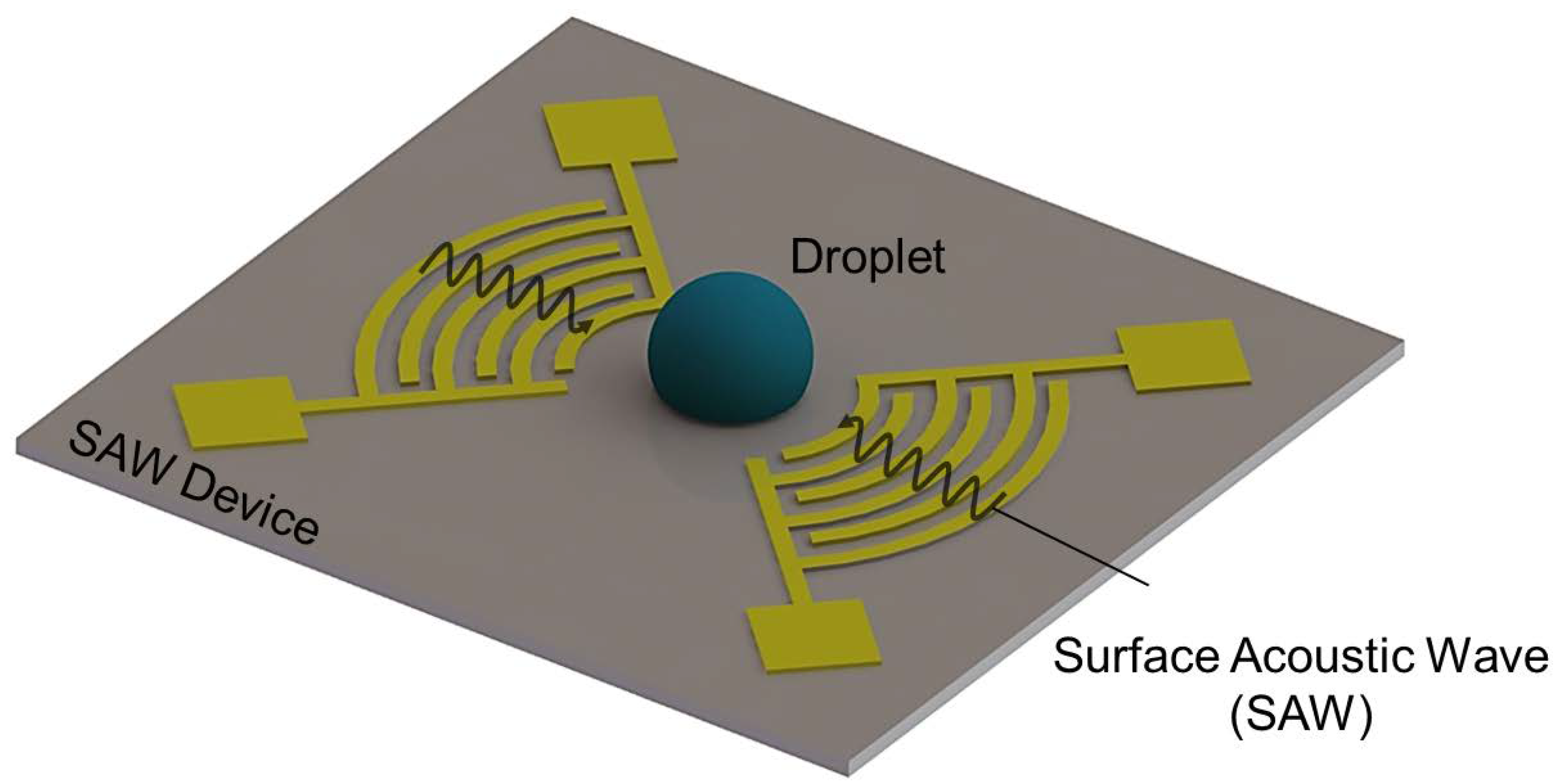
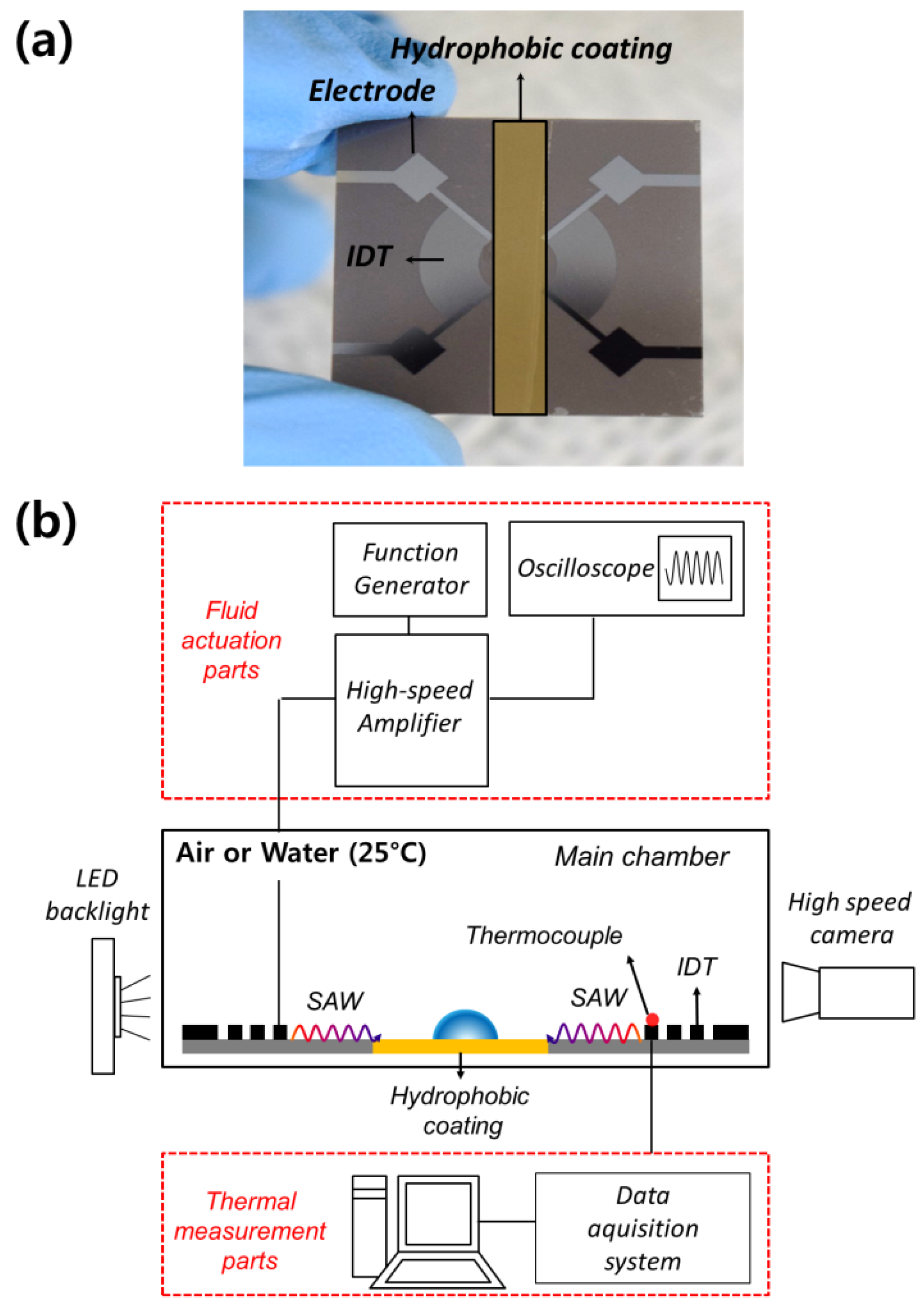
Figure 1 shows the F-SAW device used for interfacial droplet jetting. In our experiment, the F-SAW device was designed with a 20-pair interdigital transducer (IDT) electrode with 90° arc and width of 50 μm. The operating frequency was 20 MHz (λSAW ≈ 200 μm), and the focal distance was set at 2 cm from the closest finger electrode. The IDT was deposited using a UV photolithography process (500 μm thickness) on a 128°-rotated YX-cut LiNbO3 (Roditi, London, UK) piezoelectric substrate with an Al electrode of 500 nm thickness. It is known that the acoustic radiation generated by F-SAW on a hydrophobic surface induces centralized inertial body forces when jetted into the droplet, which improves jetting performance [27,28]. Therefore, the surface of the droplet loading substrate was made hydrophobic by Teflon using a spray coating method. The sprayed Teflon AF (NABAKEM, TC-100, Pyeongtaek, Korea) layer was then cured at 150 °C for 60 min to form a hydrophobic region (θc ~ 105 ± 2°), as shown in Figure 2a.
2.2. Fabrication Process of the F-SAW Device
The LiNbO3 wafer was cleaned with acetone and an aluminum layer of 500 nm was then deposited using an e-beam evaporator. Positive photoresist (PR) (AZ Electronic Materials, AZ GXR-601 (14 CP), Somerville, NJ, USA) was used as a coating. The sample was exposed to UV light using a prefabricated mask. Next, the sample was developed using CD 30 solution. At this stage, only the PR remained in the IDT-shaped part, and the aluminum layer of the remaining part was etched using the dry etching process. Finally, PR was removed with acetone, and only the IDT shape remained.
2.3. Experimental System of the SAW Device
The F-SAW was generated using an AC signal (~20 MHz) from a function generator (Agilent, 33220A, Santa clara, CA, USA) with an IDT and RF amplifier (Mini-circuits, LYX 22+, Brooklyn, NY, USA). To visualize the jet flow induced by F-SAW, a high-speed camera (Speedsense M310, Dantec, Skovlunde, Denmark) equipped with 80 W LED illumination and zoom lens (Karl Zeiss, macro 100 mm, Oberkochen, Germany) was used with a shadowgraph technique at 1000 fps. A volume of 10 μL of water was manually injected into the center of the F-SAW device using a micropipette (Eppendorf Research Plus, Hamburg, Germany). The heat transfer experiment was carried out by fixing a K-type thermocouple on the IDT with a high-thermal-conductivity silver paste (Humantech, ELCOAT P-100, Seoul, Korea). The surface temperature from the thermocouple was measured at 2 Hz. Figure 2b shows a schematic view of the experimental setup of this study.
2.4. Uncertainty Analysis
All errors related to the experiment were estimated with a 95% confidence level using measured data for each variable. Uncertainty analysis, based on Moffat’s method, was performed on the main variables described in the above data reduction procedure as well as on the basic dimensional variables [34]. The dimension error of the IDT pattern of the F-SAW device was 0.2% due to the uncertainty of the photolithography process. The temperature measurement error by the thermocouples was 1.32 K. The input power uncertainty was determined as 1.4% using the uncertainty relationship (δP″/P″) = [(δV″/V″)2 + (δI″/I”)2]1/2, which considers the bias errors of the voltage and current of the function generator and amplifier at moderate operating input power (10 W). In terms of the jet shadow images obtained from the visualization, the pixel uncertainty in the jet height was ±0.1 mm.
3. Results and Discussion
3.1. Interfacial Droplet Jetting Characteristics of the F-SAW Device
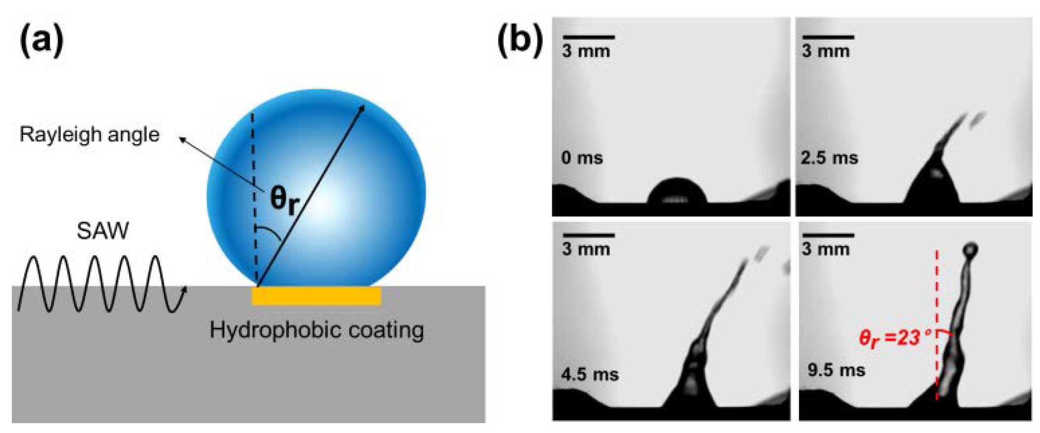
Figure 3a shows the diffraction at the pinning point of the droplet when the surface acoustic wave is generated on one side of the droplet. This diffraction is caused by the mismatch between the propagation velocities in water and the substrate, and is called the Rayleigh angle [27,28]. The acoustic radiation force due to SAW is converted into inertial body forces at the contact line of the loaded droplet. When these inertial body forces from SAW overcome the surface tension of the loaded droplet, the entire droplet shape changes into an elongated jet shape, resulting in jet flow generation. The Rayleigh angle can be derived from Equation (1):
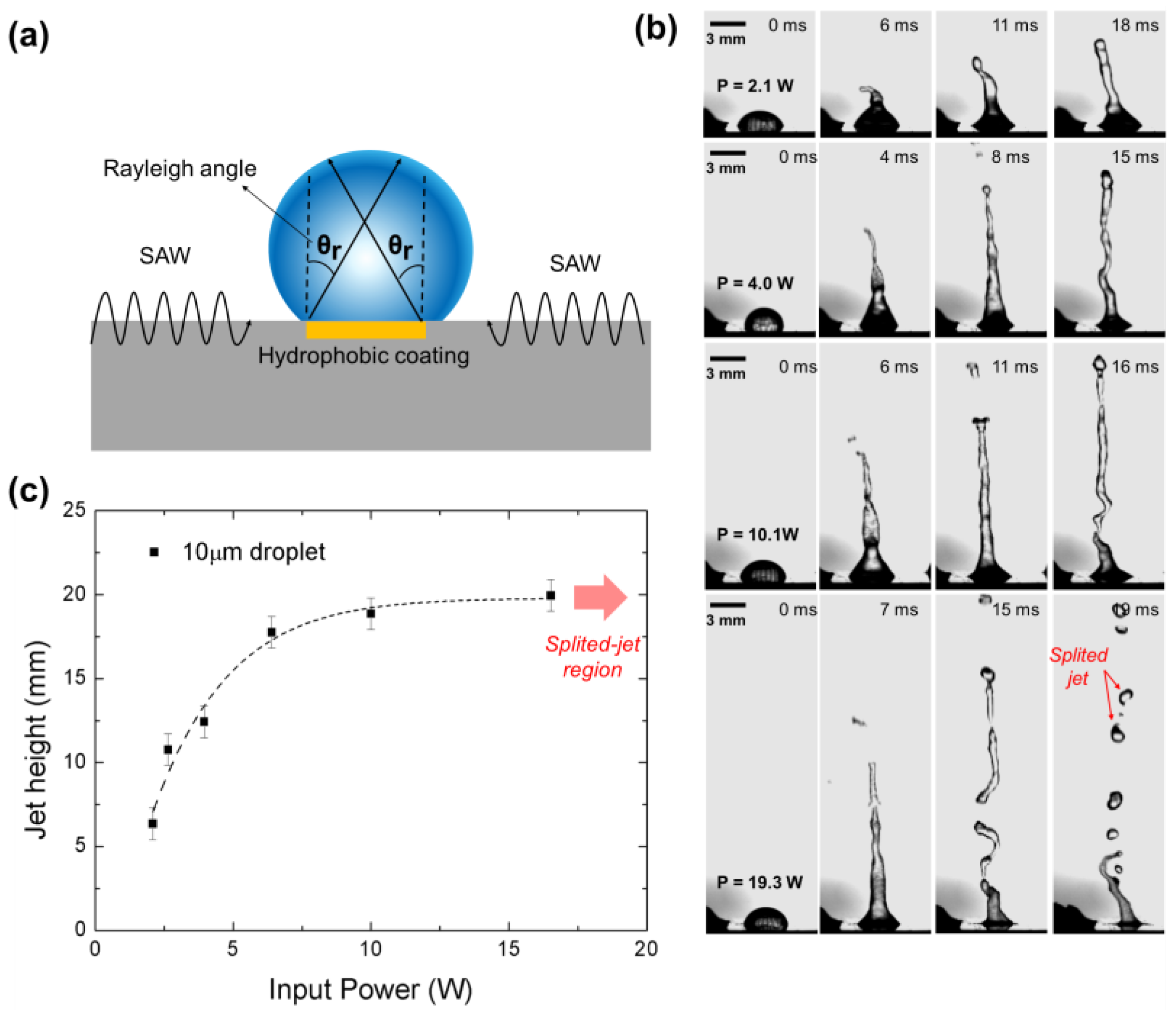
where θSAW, cl, and cs are the mean jetting angle, sound velocity (1495 m/s) in water, and sound velocity (3990 m/s) in the LiNbO3 piezoelectric substrate, respectively. According to this principle, the acoustic radiation generated by SAW is jetted into the droplet and converted into the body force, which is jetted at the Rayleigh angle. From Equation (1), the Rayleigh angle in our experiment was 23°. Therefore, to check the jet angle due to the F-SAW device, we conducted the shadowgraph visualization experiment. Figure 3b shows the variations in jetting behavior over time, and confirms the Rayleigh angle of approximately 22 ± 2.1°, which is almost consistent with the theoretical value. From this result, we claim that the reliability of the F-SAW device fabricated by the photolithography process can manipulate the droplet. The Rayleigh angle is observed by the shadow visualization method, as shown by the lower right photograph in Figure 3b. As shown in Figure 4a, when SAW is generated from both sides, it directly diffracts at the pinning points on both sides of the droplet. One requirement for creating such a jet flow is that inertial body forces should overcome the surface tension of the droplet. When this condition is satisfied, the entire droplet is deformed into an elongated jet shape. Specifically, as can be seen in the top column of Figure 4b, the sharp pinching point is instantaneously formed at the apex of the droplet. In addition, most of the inertial body forces are concentrated at the droplet vertices, resulting in very fast jet flow. In this study, the jetting flow height according to the input power was observed by varying the input power in a relatively wide range (2–19 W) for quantitative understanding of the jetting flow characteristics. As shown in Figure 4b, the jet becomes longer with increasing input power. As can be seen in the bottom image of Figure 4b, when the jet radius becomes thinner owing to the high inertial force, it splits into multiple droplet jets. Specifically, as the input power increases, as shown in Figure 4c, the jet length tends to converge to approximately 20 mm. Therefore, it is confirmed that the jet radius becomes thinner because of multiple droplet jetting when the inertial force is approximately 16 W or greater. Further research will examine the relationship between the initial jet velocity and the jet geometry by analyzing the jet flow more precisely.
3.2. Thermal Measurement Results of the SAW Device in Air and Water
When high RF power is applied to the F-SAW device, significant acoustic heating occurs [27,28,29,30,31,32,33]. Acoustic heating is a common phenomenon in SAW-based devices. Although the wave displacement of the LiNbO3 substrate is only a few nanometers [31], very high frequency mechanical vibration (20 MHz) causes a large temperature increase. Since the speed of the SAW depends on the substrate temperature, acoustic heating causes a change in the operating frequency and performance of the F-SAW device. Therefore, the heat measurement in the F-SAW device is important for microfluidic applications owing to its direct effect on such phenomena as acoustic streaming, pumping, and jetting.
Figure 5a shows the results of the measured surface temperature for increasing input RF power of the F-SAW device. In this study, the lower surface of the F-SAW device was bonded with an insulating tape with extremely low thermal conductivity (k = 0.03 W/m·K), resulting in a conduction effect under the substrate compared with the one at the top surface of the F-SAW device. As shown in Figure 5a, the maximum temperature recorded was ~129 °C at RF power of 13 W in the air and ~28.5 °C in water. The resonance frequency of the F-SAW device increases linearly with the increase in the surface temperature of the F-SAW device. This causes a change in the resonance frequency, which, in turn, decreases the performance of the F-SAW device. Therefore, it is important to evaluate the temperature dependence of the resonance frequency shift. The center resonance frequency of the F-SAW device as a function of temperature is given by
where α is the temperature coefficient of the center frequency (TCF), defined as Δf/(fiΔT) (fi stands for the frequency at 20 °C). The TCF of LiNBO3 is known to be 80 ppm/K for 500 μm bulk wafers [33]. Therefore, according to Equation (2), as shown in Figure 5, the resonance frequency shift of the F-SAW device is 0.8% at the maximum temperature (~129 °C) in air, but only 0.04% at the maximum temperature (~28.5 °C) in water. In general, piezoelectric actuators (i.e., F-SAW devices, ultrasonic motors) are known to experience drastic declines in performance when the resonant frequency changes by more than ±0.5% [35]. When the F-SAW device is in water, because the results are within the safe range, the performance of the F-SAW device can be maintained. However, the performance of the F-SAW device is expected to decrease sharply in air because of the large frequency shift of 0.8%. In short, the resonance frequency shift of F-SAW is reduced to 1/20 in water compared with that in air. Therefore, we can confirm that the performance of the F-SAW device was well maintained in water compared with in the air environment. Specifically, as shown in Figure 5b, when RF power of 13 W was applied, the temperature increased by ~106.2 °C, whereas it increased by only ~5.7 °C in water during the operating time (250 s). In addition, after turning the F-SAW device off, it takes a long time to reach the steady state (more than 250 s) in the air environment, whereas in water, this time is reduced to only 25 s. The low temperature rise and fast cooling rate of the F-SAW device in water are attributed to the difference in the heat transfer coefficient between air and water. In classical heat transfer studies [36], the heat transfer coefficient in air under natural convection conditions is only 5–10 W/m2K, but reaches 100–1200 W/m2K in water. The maximum heat transfer coefficient in water is 120 times greater than that in air. Therefore, through the heat transfer experiment of F-SAW in air and water, we confirmed that the cooling performance of the F-SAW device in water can be significantly enhanced. Specifically, the temperature increase in the water was 1/20 of that in the air owing to the very high convective heat transfer coefficient of the water, resulting in the prevention of performance degradation of the F-SAW device.
Since biological cells and tissues are very sensitive to the temperature, these thermal issues of the F-SAW devices would be a big problem for use as a nozzle-less liquid jet in the commercial 3D bioengineering field. Therefore, in further research, we will conduct additional thermal experiments (i.e., evaluations of the temperature variations and stability of the inside of the liquid jet by the installation of Peltier elements for cooling of the F-SAW device) to solve the thermal issues of the F-SAW device.
4. Conclusions
In this study, we demonstrated the interfacial jetting characteristics and thermal stability of an F-SAW device. The heights of the jet flows of the F-SAW device were analyzed along with the temperature variations of the F-SAW surface with increasing input power. Interfacial jet flows of the F-SAW device were measured using a high-speed camera, and the surface temperature was evaluated with K-type thermocouples. Specifically, the interfacial droplet jetting characteristics (jet angle and height) were analyzed for two different cases by applying a single IDT and two opposite IDTs. The measured Rayleigh angle (22 ± 2.1°) of the single jet, obtained from the visualization experiment, was consistent with the theoretical value for a single IDT. In the case of two opposite IDTs, in the high-input-power region, the single jet collapsed into multiple droplets when the jet radius decreased to its limit, owing to the high inertial body forces induced by F-SAW. Finally, we demonstrate that the maximum temperature increase of the F-SAW device in water was 1/20 of that in air, owing to the very high convective heat transfer coefficient of the water, and resulting in the prevention of performance degradation of the F-SAW device. These thermal issues of the F-SAW devices would be a big problem when using the F-SAW devices as a nozzle-less liquid jet in the 3D bioengineering field due to the high temperature sensitivity of biological tissues and cells [18,37,38]. Therefore, additional intensive thermal studies for the F-SAW device are needed to solve these thermal problems.
Author Contributions
D.L. fabricated the devices, performed the experiments, analyzed the data, wrote the paper, and prepared figures. N.L. and G.C. analyzed the data and reviewed drafts of the paper. H.H.C. conceived and designed the experiments, analyzed the data and wrote the paper.
Acknowledgments
This work was supported by the Center for Advanced MetaMaterials (CAMM) funded by the Ministry of Science, ICT and Future Planning as Global Frontier Project (CAMM-No. NRF2014M3A6B3063716), and the Human Resources Development program (No. 20174030201720) of the Korea Institute of Energy Technology Evaluation and Planning (KETEP), grant funded by the Korea government Ministry of Trade, Industry and Energy.
Conflicts of Interest
The authors declare no conflict of interest.
References
- Jakubik, W.P. Surface acoustic wave-based gas sensors. Thin Solid Films 2011, 520, 986–993. [Google Scholar] [CrossRef]
- Liu, X.; Wang, J.Y.; Mao, X.B.; Ning, Y.; Zhang, G.J. Single-shot analytical assay based on graphene-oxide-modified surface acoustic wave biosensor for detection of single-nucleotide polymorphisms. Anal. Chem. 2015, 87, 9352–9359. [Google Scholar] [CrossRef] [PubMed]
- Mhatre, S.; Zigelman, A.; Abezgauz, L.; Manor, O. Influence of a Propagating Megahertz Surface Acoustic Wave on the Pattern Deposition of Solute Mass off an Evaporating Solution. Langmuir 2016, 32, 9611–9618. [Google Scholar] [CrossRef] [PubMed]
- Lin, Q.; Li, Y.; Yang, M. Highly sensitive and ultrafast response surface acoustic wave humidity sensor based on electrospun polyaniline/poly (vinyl butyral) nanofibers. Anal. Chim. Acta 2012, 748, 73–80. [Google Scholar] [CrossRef] [PubMed]
- Perry, M.; McKeeman, I.; Saafi, M.; Niewczas, P. Wireless surface acoustic wave sensors for displacement and crack monitoring in concrete structures. Smart Mater. Struct. 2016, 25, 035035. [Google Scholar] [CrossRef] [Green Version]
- Toma, K.; Miki, D.; Kishikawa, C.; Yoshimura, N.; Miyajima, K.; Arakawa, T.; Yatsuda, H.; Mitsubayashi, K. Repetitive immunoassay with a surface acoustic wave device and a highly stable protein monolayer for on-site monitoring of airborne dust mite allergens. Anal. Chem. 2015, 87, 10470–10474. [Google Scholar] [CrossRef] [PubMed]
- Toma, K.; Horibe, M.; Kishikawa, C.; Yoshimura, N.; Arakawa, T.; Yatsuda, H.; Shimomura, H.; Mitsubayashi, K. Rapid and repetitive immunoassay with a surface acoustic wave device for monitoring of dust mite allergens. Sens. Actuators B Chem. 2017, 248, 924–929. [Google Scholar] [CrossRef]
- Dong, M.; Iervolino, E.; Santagata, F.; Zhang, G.; Zhang, G. Silicon microfabrication based particulate matter sensor. Sens. Actuators A Phys. 2016, 247, 115–124. [Google Scholar] [CrossRef]
- Witte, C.; Reboud, J.; Wilson, R.; Cooper, J.; Neale, S. Microfluidic resonant cavities enable acoustophoresis on a disposable superstrate. Lab Chip 2014, 14, 4277–4283. [Google Scholar] [CrossRef] [PubMed] [Green Version]
- Shilton, R.; Tan, M.K.; Yeo, L.Y.; Friend, J.R. Particle concentration and mixing in microdrops driven by focused surface acoustic waves. J. Appl. Phys. 2008, 104, 014910. [Google Scholar] [CrossRef]
- Destgeer, G.; Im, S.; Ha, B.H.; Jung, J.H.; Ansari, M.A.; Sung, H.J. Adjustable, rapidly switching microfluidic gradient generation using focused travelling surface acoustic waves. Appl. Phys. Lett. 2014, 104, 023506. [Google Scholar] [CrossRef]
- Destgeer, G.; Ha, B.H.; Park, J.; Jung, J.H.; Alazzam, A.; Sung, H.J. Microchannel anechoic corner for size-selective separation and medium exchange via traveling surface acoustic waves. Anal. Chem. 2015, 87, 4627–4632. [Google Scholar] [CrossRef] [PubMed]
- Destgeer, G.; Lee, K.H.; Jung, J.H.; Alazzam, A.; Sung, H.J. Continuous separation of particles in a PDMS microfluidic channel via travelling surface acoustic waves (TSAW). Lab Chip 2013, 13, 4210–4216. [Google Scholar] [CrossRef] [PubMed]
- Tan, M.K.; Friend, J.R.; Yeo, L.Y. Microparticle collection and concentration via a miniature surface acoustic wave device. Lab Chip 2007, 7, 618–625. [Google Scholar] [CrossRef] [PubMed]
- Luo, J.T.; Geraldi, N.; Guan, J.; McHale, G.; Wells, G.; Fu, Y.Q. Slippery liquid-infused porous surfaces and droplet transportation by surface acoustic waves. Phys. Rev. Appl. 2017, 7, 014017. [Google Scholar] [CrossRef]
- Lee, T.; Baac, H.W.; Ok, J.G.; Youn, H.S.; Guo, L.J. Nozzle-free liquid microjetting via homogeneous bubble nucleation. Phys. Rev. Appl. 2015, 3, 044007. [Google Scholar] [CrossRef]
- Fu, C.; Quan, A.J.; Luo, J.T.; Pang, H.; Guo, Y.; Wu, Q.; Fu, Y.Q. Vertical jetting induced by shear horizontal leaky surface acoustic wave on 36° YX LiTaO3. Appl. Phys. Lett. 2017, 110, 173501. [Google Scholar] [CrossRef]
- Castro, J.O.; Ramesan, S.; Rezk, A.R.; Yeo, L.Y. Continuous tuneable droplet ejection via pulsed surface acoustic wave jetting. Soft Matter 2018. [Google Scholar] [CrossRef] [PubMed]
- Wu, T.T.; Tang, H.T.; Chen, Y.Y.; Liu, P.L. Analysis and design of focused interdigital transducers. IEEE Trans. Ultrason. Ferroelectr. Freq. Control 2005, 52, 1384–1392. [Google Scholar] [PubMed]
- Qi, A.; Yeo, L.Y.; Friend, J.R. Interfacial destabilization and atomization driven by surface acoustic waves. Phys. Fluids 2008, 20, 074103. [Google Scholar] [CrossRef]
- Qi, A.; Friend, J.R.; Yeo, L.Y.; Morton, D.A.; McIntosh, M.P.; Spiccia, L. Miniature inhalation therapy platform using surface acoustic wave microfluidic atomization. Lab Chip 2009, 9, 2184–2193. [Google Scholar] [CrossRef] [PubMed]
- Shilton, R.J.; Yeo, L.Y.; Friend, J.R. Quantification of surface acoustic wave induced chaotic mixing-flows in microfluidic wells. Sens. Actuators B Chem. 2011, 160, 1565–1572. [Google Scholar] [CrossRef]
- Luong, T.D.; Phan, V.N.; Nguyen, N.T. High-throughput micromixers based on acoustic streaming induced by surface acoustic wave. Microfluid. Nanofluid. 2011, 10, 619–625. [Google Scholar] [CrossRef]
- Dentry, M.B.; Friend, J.R.; Yeo, L.Y. Continuous flow actuation between external reservoirs in small-scale devices driven by surface acoustic waves. Lab Chip 2014, 14, 750–758. [Google Scholar] [CrossRef] [PubMed]
- Schmid, L.; Wixforth, A.; Weitz, D.A.; Franke, T. Novel surface acoustic wave (SAW)-driven closed PDMS flow chamber. Microfluid. Nanofluid. 2012, 12, 229–235. [Google Scholar] [CrossRef]
- Franke, T.; Abate, A.R.; Weitz, D.A.; Wixforth, A. Surface acoustic wave (SAW) directed droplet flow in microfluidics for PDMS devices. Lab Chip 2009, 9, 2625–2627. [Google Scholar] [CrossRef] [PubMed]
- Darmawan, M.; Byun, D. Focused surface acoustic wave induced jet formation on superhydrophobic surfaces. Microfluid. Nanofluid. 2015, 18, 1107–1114. [Google Scholar] [CrossRef]
- Tan, M.K.; Friend, J.R.; Yeo, L.Y. Interfacial jetting phenomena induced by focused surface vibrations. Phys. Rev. Lett. 2009, 103, 024501. [Google Scholar] [CrossRef] [PubMed]
- Greco, G.; Agostini, M.; Shilton, R.; Travagliati, M.; Signore, G.; Cecchini, M. Surface Acoustic Wave (SAW)-Enhanced Chemical Functionalization of Gold Films. Sensors 2017, 17, 2452. [Google Scholar] [CrossRef] [PubMed]
- Kondoh, J.; Shimizu, N.; Matsui, Y.; Sugimoto, M.; Shiokawa, S. Development of temperature-control system for liquid droplet using surface acoustic wave devices. Sens. Actuators A Phys. 2009, 149, 292–297. [Google Scholar] [CrossRef]
- Zhou, J.; DeMiguel-Ramos, M.; Garcia-Gancedo, L.; Iborra, E.; Olivares, J.; Jin, H.; Luo, J.; Elhady, A.; Dong, S.; Wang, D. Characterisation of aluminium nitride films and surface acoustic wave devices for microfluidic applications. Sens. Actuators B Chem. 2014, 202, 984–992. [Google Scholar] [CrossRef]
- Ha, B.H.; Lee, K.S.; Destgeer, G.; Park, J.; Choung, J.S.; Jung, J.H.; Shin, J.H.; Sung, H.J. Acoustothermal heating of polydimethylsiloxane microfluidic system. Sci. Rep. 2015, 5, 11851. [Google Scholar] [CrossRef] [PubMed] [Green Version]
- Shilton, R.J.; Mattoli, V.; Travagliati, M.; Agostini, M.; Desii, A.; Beltram, F.; Cecchini, M. Rapid and controllable digital microfluidic heating by surface acoustic waves. Adv. Funct. Mater. 2015, 25, 5895–5901. [Google Scholar] [CrossRef]
- Moffat, R.J. Describing the uncertainties in experimental results. Exp. Therm. Fluid Sci. 1988, 1, 3–17. [Google Scholar] [CrossRef] [Green Version]
- Xu, X.; Liang, Y.; Lee, H.; Lin, W.; Lim, S.; Lee, K.; Shi, X. Mechanical modeling of longitudinal oscillation ultrasonic motors and temperature effect analysis. Smart Mater. Struct. 2003, 12, 514. [Google Scholar] [CrossRef]
- Hollands, K.; Raithby, G.; Konicek, L. Correlation equations for free convection heat transfer in horizontal layers of air and water. Int. J. Heat Mass Transf. 1975, 18, 879–884. [Google Scholar] [CrossRef]
- Winkler, A.; Brünig, R.; Faust, C.; Weser, R.; Schmidt, H. Towards efficient surface acoustic wave (SAW)-based microfluidic actuators. Sens. Actuators A Phys. 2016, 247, 259–268. [Google Scholar] [CrossRef]
- Kiebert, F.; König, J.; Kykal, C.; Schmidt, H. Measurements of streams agitated by fluid loaded SAW-devices using a volumetric 3-component measurement technique (V3V). Phys. Procedia 2015, 70, 25–29. [Google Scholar] [CrossRef]
Figure 1.
Schematics of the focused surface acoustic wave (F-SAW) device for interfacial droplet jetting.
Figure 1.
Schematics of the focused surface acoustic wave (F-SAW) device for interfacial droplet jetting.

Figure 2.
(a) Photographs of the structure of the F-SAW device for interfacial droplet jetting. (b) Schematics of experimental apparatus for interfacial droplet jetting and thermal measurement setup of the F-SAW device in the air and water.
Figure 2.
(a) Photographs of the structure of the F-SAW device for interfacial droplet jetting. (b) Schematics of experimental apparatus for interfacial droplet jetting and thermal measurement setup of the F-SAW device in the air and water.

Figure 3.
(a) The principle of the interfacial droplet jetting of the F-SAW device and (b) photographs of the interfacial droplet jetting angle under the single-IDT experimental case.
Figure 3.
(a) The principle of the interfacial droplet jetting of the F-SAW device and (b) photographs of the interfacial droplet jetting angle under the single-IDT experimental case.

Figure 4.
(a) The principle of the interfacial droplet jetting of the F-SAW device and (b) photographs of interfacial droplet jetting under the dual opposite IDT experimental case. (c) The interfacial jet height of the F-SAW device as input power increases.
Figure 4.
(a) The principle of the interfacial droplet jetting of the F-SAW device and (b) photographs of interfacial droplet jetting under the dual opposite IDT experimental case. (c) The interfacial jet height of the F-SAW device as input power increases.

Figure 5.
Thermal measurement results for the F-SAW device in air and water. (a) Temperature increases and resonance frequency shift of F-SAW device with input power and (b) temperature variation of F-SAW device with time in air and water.
Figure 5.
Thermal measurement results for the F-SAW device in air and water. (a) Temperature increases and resonance frequency shift of F-SAW device with input power and (b) temperature variation of F-SAW device with time in air and water.

© 2018 by the authors. Licensee MDPI, Basel, Switzerland. This article is an open access article distributed under the terms and conditions of the Creative Commons Attribution (CC BY) license (http://creativecommons.org/licenses/by/4.0/).
Share and Cite
MDPI and ACS Style
Lee, D.; Lee, N.; Choi, G.; Cho, H.H. Heat Transfer Characteristics of a Focused Surface Acoustic Wave (F-SAW) Device for Interfacial Droplet Jetting. Inventions 2018, 3, 38. https://doi.org/10.3390/inventions3020038
AMA Style
Lee D, Lee N, Choi G, Cho HH. Heat Transfer Characteristics of a Focused Surface Acoustic Wave (F-SAW) Device for Interfacial Droplet Jetting. Inventions. 2018; 3(2):38. https://doi.org/10.3390/inventions3020038
Chicago/Turabian StyleLee, Donghwi, Namkyu Lee, Geehong Choi, and Hyung Hee Cho. 2018. "Heat Transfer Characteristics of a Focused Surface Acoustic Wave (F-SAW) Device for Interfacial Droplet Jetting" Inventions 3, no. 2: 38. https://doi.org/10.3390/inventions3020038