An Improved Control Strategy for Three-Phase Power Inverters in Islanded AC Microgrids
by
 ,
,
Muhammad Zahid Khan
1,* ,
,
Muhammad Mansoor Khan
1, 
Huawei Jiang
2,
Khurram Hashmi
1 and
Muhammad Umair Shahid
1 1
School of Electronic, Information and Electrical Engineering (SEIEE), Shanghai Jiao Tong University, Shanghai 200240, China
2
State Grid Wuxi Power Supply Company, Wuxi 214000, China
*
Author to whom correspondence should be addressed.
Inventions 2018, 3(3), 47; https://doi.org/10.3390/inventions3030047
Submission received: 7 June 2018
/
Revised: 2 July 2018
/
Accepted: 10 July 2018
/
Published: 11 July 2018
(This article belongs to the Special Issue Microgrids 2018)
Abstract
:Microgrids (MGs) are composed of multiple distributed generators (DGs) interfaced to micronetwork through paralleled connected power inverters (PIs). Load sharing among multiple DG units is an important task for autonomous operation of microgrids. In order to realize satisfactory power sharing and voltage regulation between DG units, different voltage droop control strategies have been reported in the literature. In the medium voltage (MV) microgrids, power sharing, and voltage regulation often deteriorate due to dependence on nontrivial feeder impedances. The conventional control strategies are subject to steady-state active and reactive power-sharing errors along with system voltage and frequency deviations. Furthermore, complex microgrid configurations either in looped or meshed networks often make power balancing and voltage regulations more challenging. This paper presents an improved control strategy that can be extended for radial networks in order to enhance the accuracy of power sharing and voltage regulation. The proposed control strategy considers load voltage magnitude regulation as opposed the voltage regulation at inverters terminals. At the same time, a supervisory control loop is added to observe and correct system frequency deviations. This proposed method is aimed at replacing paralleled inverter control methods hitherto used. Simulation studies of the proposed scheme in comparison with the conventional control strategy in MATLAB/Simulink validate the effectiveness of the proposed strategy.
1. Introduction
Microgrids are small-scale power systems that make possible the effective integration of distributed generators (DGs) [1]. A DG has advantages of high-energy utilization rate, pollution reduction, low power transmission losses, and flexible installation locations [2]. DG units present a higher degree of control and operation as compared to the conventional generators, which allows the microgrids to play a significant role in order to maintain the stability of electrical networks [3,4]. Furthermore, DG units provides the clean and renewable power to close consumer’s end. Therefore, it reduces the strain on conventional transmission and distribution infrastructures [5,6].
Power-electronics-based MGs are convenient when integrating renewable energy resources, active loads and DG units [1,7]. The DG units of a microgrid can be classified into grid-following and grid-forming DG units [6,8]. The DG units are controlled as grid following in grid-connected mode. Grid-following inverter’s control strategies are described in [9,10]. However, in islanding mode, the distributed power inverters interfaces (DPIs) between load and microsource are governed by the droop control algorithm, which are responsible for the voltage regulation and power sharing in accordance with their ratings and corresponding energy source power. Hence, the control of paralleled connected power inverters has been investigated in recent years [11,12,13].
Conventionally, the frequency and voltage magnitude droop are used as decentralized control schemes among DG units [11,12]. It can be seen as primary control of a synchronous machine. With the help of droop control active power sharing can be achieved among these DGs units. However, reactive power sharing is highly dependent on a DG unit’s output filter and feeder impedances [11,14,15,16]. The identical feeder impedance could be unequal as various DG units and load are located at different distances to each other. The unequal LCL-filter’s impedance among various DGs units are due to different design considerations and system conditions [15]. In addition, configuration of microgrid network and existence of local loads often aggravate the power balancing problem. Therefore, power sharing of conventional droop control can be affected by mismatch of feeder impedances and make islanded microgrids less flexible and reliable [11,15].
To solve the power control issue, a considerable number of control schemes based on droop concept have been proposed, which are classified into four main categories: (1) virtual framework structure-based method [17,18]; (2) conventional and variants of the droop control [18,19]; (3) the hybrid droop/signal injection method [18,20]; and (4) “construct and compensate” based methods [20,21]. Furthermore, in [14] reactive power and the harmonic power, sharing errors were decreased by injecting noncharacteristic harmonic current. Although the power balancing issue was addressed, the power quality of the microgrid was degraded by steady state voltage distortions. The author proposed an Q-V dot droop in [14]. It can be observed that when local loads are added, then reactive power sharing improvement is not obvious. The virtual output impudence control in [11] is proposed to match the identical power line impedances. To decrease the droop control’s dependence on the DG’s output filter, Sao and Lehn [20] presented compensation of the voltage magnitude drop. Nevertheless, this scheme may still be affected by mismatched feeder impedances.
Usually, in a grid-forming inverter’s control strategies [6], the loads are directly connected with DG units however, these loads can be connected with looped or mesh network type configuration [22,23]. These complex microgrid configurations either in looped or mesh networks often make power balancing and voltage regulations more challenging [7,23]. In response to a complex AC microgrid configuration, this paper presents an improved control strategy which is extended for multiple feeders with limited number of grid forming nodes in radial networks. This strategy considers the load voltage magnitude regulation rather than voltage regulation at inverter terminals. Furthermore, a supervisory loop also been added to restore the frequency deviations.
2. Network Model
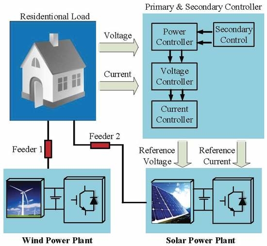
Figure 1 illustrates the configuration of a microgrid. As shown, microgrids are composed of multiple DG units and loads. Every DG unit is interfaced to the microgrid with distributed power inverters where these power inverters are connected to AC bus via their respective feeder. Secondary central controller controlled the status of main grid and microgrid [24]. MGs can be connected (grid-following mode) or disconnected (islanded mode) from the main grid by using static transfer switch (STS) at the point of common coupling (PCC). Active and reactive power references are usually assigned by the central controller in grid-following mode. In this mode of operation, power balancing is not the real concern. However, by switching the microgrid into islanded mode, the load demand must be properly shared by DG units.
In islanded operation of a microgrid, DG units as shown in Figure 1 can operate using the conventional active power-frequency (P-f) and reactive power-voltage magnitude (Q-V) droop as:
where, ω *, V *, DP and DQ are the nominal frequency, nominal voltage magnitude, active and reactive power slopes, respectively of DG unit. The active power p and reactive power Q are measured after the low-pass filtration. Instantaneous voltage reference can be acquired with derived angular frequency and voltage magnitude in Equations (1) and (2).
Mathematical Model
A simplified microgrid circuit is shown in Figure 2b with two DG units that are parallel connected, R1 and X1, R2 and X2 are the feeder impedances of DG1 and DG2, respectively. As shown in Figure 2a, the complex power drawn to the kth ac bus can be written as:
where, Pi and Qi are the active and reactive power injected at each node by DG inverters. Power flow through feeder line impedances can be expressed as:
where, Vi and Vk are the magnitude of inverter output voltage and common bus voltage, respectively, while Pi and Qi are the active and reactive powers flowing from ith inverter terminal to kth common bus voltage. represents the difference between the phase of the output impedance and power angle.
The inductive components of higher voltage (HV) and medium (MV) network are typically higher then resistive as shown in Table 1 [6], however, MV networks have inductive behaviour, therefore, it can be assumed that: and , resulting power flow can be expressed as:
where, according to Equations (8) and (9), the active power depends on power angle while reactive power injected by each inverter depends on voltage difference Vi − Vk. From Equation (6), if is supposed to be zero, then Pi will be proportional to angle and it can be expressed as:
∂k affects the ∂ik which is calculated by output voltage of DG units and line impedances. By integrating ωi, the variations in ∂ik can be regulated.
3. Proposed Control Strategy
Aforementioned, in a grid-forming inverter’s control strategies the loads are usually directly connected with DG units. However, these loads can be connected with a radial-type configuration. In this section, a proposed control strategy is discussed for such type of microgrid configurations that can be extended for multiple feeders with limited number of grid-forming nodes. To connect the secondary central controller with a DG unit’s local controllers, this strategy adopts a communication link. The proposed strategy considers the load voltage magnitude regulations rather than voltage regulation at inverter terminals. Furthermore, the load voltage magnitude is measured and converted into dq-axis components using reference frame transformation. The inverter’s output active and reactive powers are calculated based on these measurements and sent to droop controllers via low-pass filters. Droop controllers send voltages and frequency references to inner loops. The error signal is obtained after comparing the measured voltage and frequency values with reference values. These voltage and frequency deviations are periodically corrected by the secondary control loop.
3.1. Power Flow Control
The configuration of the microgrid with two DG units is shown in Figure 2b and its proposed control strategy block is illustrated in Figure 3. An inverter bridge is connected to dc power source and its output frequency and output voltages are adjusted by power, voltage and current controllers [12]. All DG units are individually formulated in its d-q frame which depends on their angular frequency ωi and angle ∂i. Each DG unit’s interfaced inverters are transferred to the d-q frame by using transformation equation [25] as:
The angle of ith DG units’ d-q fame can be written as:
Figure 4 shows the power controller block which follow the droop control strategy and it send voltage reference V*odi, and V*oqi, to inner loop. Average output active and reactive powers are obtained from instantaneous power passing low pass filters, can be denoted as:
where, the cutoff frequency of low pass filter. Instantaneous active and reactive power in d-q rotating frame can be written as:
On individual frame d-q, and are the load voltage and line current of an ith inverter. Droop technique shows the relationship between the frequency and active power p-ω, and between the voltage amplitude and reactive power Q-V can be represented as:
where ωi*, Vi*, mPi and nQi are nominal frequency, nominal voltage and droop coefficients, respectively, of ith DG unit. V*odi is the reference voltage for inner voltage loop. Q-V droop control strategy with consideration of voltage control can presented as Equation (19) by Equation (18), illustrated in Figure 3.
δVi can written as, shown in Figure 5b:
where Vi* and are the nominal voltage and average voltage (21) of all inverters. While δVi is responsible to regulate the load voltage which compensates the voltage deviation caused by droop controller.
3.2. Frequency & Voltage Regulation
The frequency regulation strategy restores the frequency deviation of the DGs to the nominal value. Frequency restoration method is given in (23) and elaborated in Figure 5a.
ωi* is the nominal reference frequency, is the measured system frequency that is being sensed at all nodes of inverters in the neighborhood of the node i being considered. is the frequency correction which is sent to frequency reference of the ith inverter node as shown in Figure 5a. Kp1 and Ki1 are proportional and integral gains for controllers.
Load node voltage regulation method is shown in Figure 5b and can be expressed as:
where, Vi* is the nominal reference voltage in d-axis, Vk is the measured system voltage in d-axis that is sensed at each DG’s interface inverters nodes in communication neighborhood of the node i. Kp1 and Ki1 are proportional and integral gains for controllers as shown in Figure 5b. Here, δVi is the voltage correction command applied to voltage reference of the ith inverter node.
4. Results and Discussion
In this section, the results obtained from conventional and proposed control strategies for power sharing, inverter terminal, load voltage, and frequency regulation are compared and discussed. The simulations on MATLAB/Simulink are conducted on circuit configuration given in Figure 2a for three phase 50 Hz islanded microgrid wherein the two paralleled connected DG1 and DG2 are connected to the shared load via feeder impedance X1–R1 and X2–R2. Same system and controller parameters have been used as shown in Table 2 [26] for both conventional and proposed control schemes but in conventional strategy the inverter terminal voltage are measured for regulation while in proposed control strategy the load voltage magnitude is measured for load voltage regulation. For sake of comparison, active power p and reactive power Q are measured on inverter terminals and at Vload for equal and unequal line impedances. However, system parameters are given follows:
- The system voltage is 230 V, 50 Hz.
- Two 60-KVA DG units are applied with output filter inductor Lf = 250 μF is to reduce ripples.
- A three-phase RL & C load is applied of value 0.8 Ω, 0.15 mH and 120 μF, respectively.
The droop controller and other parameters are given in Table 2.
4.1. Case 1: P, Q Measured at Inverters Terminals
In this case, both conventional and proposed control strategies are applied for equal and unequal line impedances. The active and reactive powers are measured at inverter terminals Vt1 and Vt2 for both schemes, as shown in Figure 2b. Conventional strategy considers the voltage regulations at inverter terminal while in proposed scheme load voltage is measured and restored at load node. Results obtained for this case are discussed below.
4.1.1. Equal Line Impedance
In this case, the system is considered symmetrical as the distance is the same from each DG to load. To verify the effectiveness of the proposed strategy, the power-sharing and voltages results are obtained from simulations as shown in Figure 6, Figure 7 and Figure 8.
Figure 6 shows the results obtained for load and inverter terminal voltages from both the conventional and proposed control scheme. In the conventional scheme, the inverter terminal voltages after regulation are stabled at 230 (phase to ground) volts as illustrated in Figure 6a while the load voltage is held stable at 215 volts with an error of 6.52% Equation (27), which shows the drawback of the conventional control scheme. This error has been compensated in a proposed scheme that stabilizes load voltage at its nominal value of 230 volts as shown in Figure 6b, which shows the effectiveness of the proposed strategy. In addition, for the powering sharing case, since the distance is equal from distribution generation DG to load. As such, identical transient trends are observed for P1, P2 and Q1, Q2 for both conventional and proposed control scheme as well as comparing results of both schemes to each other they share divergent power sharing. In the conventional scheme, power-sharing for each inverter is investigated with load Pload = P1 + P2 = 94.6 kw, Qload = Q1 + Q2 = 4.2 kvar while in proposed scheme each inverter share power with load Pload = 106.2 kw, Qload = 4760 var as illustrated in Figure 7 and Figure 8.
4.1.2. Unequal Line Impedance
The results acquired for unequal line impedances are shown in Figure 9, Figure 10 and Figure 11. It is assumed that load is located on distances with respect to DG units. The conventional and proposed control strategy has been applied on unequal line impedances set as R1 + jX1 = 0.05 + j1.099 Ω and R2 + jX2 = 0.05 + j1.3 Ω. In the conventional strategy, the load voltage error with a value of 7.82% is spotted as shown in Figure 9a this error can be compensated by the proposed scheme. As proposed strategy regulate this load voltage error and restore it by nominal load voltage value of 230 volts as shown in Figure 9b.
Because of unequal line impedances, the total reactive power is not evenly shared to load. Start-up reactive power transient error has been noticed in Figure 10a. It is observed that system stabilizes to active and reactive power within 1 s as shown in Figure 10a and Figure 11a. The slight reactive power sharing error is noticed in Figure 10b and it can be calculated with Equation (28) as the ratio of the differential of desired and measured reactive power to desired reactive power. In addition, each inverter shares Pload = 92.2 kw and Qload = 7150 var for the conventional scheme while Pload = 105 kw, and Qload = 8175 var in the proposed scheme as shown in Figure 10 and Figure 11.
4.2. Case 2: P, Q Measured at Terminal Vload
In this case, p, Q is measured at node Vload as shown in Figure 2a. Results are obtained and discussed below for equal and unequal line impedances for both conventional and proposed control strategies.
4.2.1. Equal Line Impedance
Figure 12 shows the results obtained for voltages from conventional and proposed control schemes. The load voltage error caused by droop in islanded microgrid is compensated in the proposed strategy, which stabled the load voltage at its nominal value of 230 volts as shown in Figure 12b. In the conventional scheme, power sharing Pload = 89.2 kw, Qload = 2550 var injected towards Vload node by each inverters is slightly lesser as proposed scheme shared Pload = 101 kw, Qload = 2900 var as illustrated in Figure 13 and Figure 14.
4.2.2. Unequal Line Impedance
In this case, line impedances set as R1 + jX1 = 0.05 + j1.099 Ω and R2 + jX2 = 0.05 + j1.3 Ω. In conventional control scheme, the slightly higher load voltage error is noticed with value of 7.82% as shown in Figure 15a this error is eliminated by proposed scheme and restored the load voltage at nominal value as depicted in Figure 15b.
In conventional control scheme, the startup divergent trend has been spotted for active power and it stabilizes within 0.5 s as shown in Figure 16a while in proposed scheme the active power is proportionally shared with a value of 99.7 kw. Slightly higher reactive power sharing error is observed for the conventional control scheme as shown in Figure 17a. Reactive power of inverter1 is gradually increased and stabilizes within 0.7 s to values of +3400 var while inverter2 shares −850 var. However, in proposed control scheme reactive power is proportionally shared after a small start-up transient trend as depicted in Figure 17b.
Frequency regulation results are presented in Figure 18. Frequency is gradually restored to the nominal value and remains within nominal frequency value of ±0.5 Hz.
5. Conclusions
In order to improve the overall performance of a droop controlled microgrid, an improved control strategy is proposed and analyzed. It is demonstrated that the proposed strategy can be extended for radial configurations. Load voltage deviations have been eliminated and load power sharing accuracy has been enhanced along with frequency restoration. The proposed control strategy consists of two decoupled methods. The Q-V loops control the sharing of reactive power and load voltage restoration while P-f control loops address active power sharing and frequency restoration. Both sets of control loops have been implemented in a centralized manner. The validity of the proposed scheme has been tested through simulation studies on an islanded ring-feeder network. The results of the simulation study in MATLAB’s Simpower systems in comparison to the conventional strategy verify the effectiveness of the proposed methodology.
Author Contributions
M.Z.K. proposed the idea for writing the manuscript. M.M.K. and K.H. suggested the literature and supervised in writing the manuscript. K.H. helped M.Z.K. in writing and formatting. M.U.S. helped in modifying the figures and shared the summary of various credible articles to be included in this manuscript. J.H. helped in system parameters to make the simulation test possible.
Conflicts of Interest
The authors declare no conflict of interest.
References
- Lasseter, R.H. Smart distribution: Coupled microgrids. Proc. IEEE 2011, 99, 1074–1082. [Google Scholar] [CrossRef]
- Lasseter, R.H.; Paigi, P. Microgrid: A Conceptual Solution. In Proceedings of the 2004 IEEE 35th Annual Power Electronics Specialists Conference, Aachen, Germany, 20–25 June 2004; pp. 4285–4290. [Google Scholar]
- Rita, A.; Fazio, D.; Russo, M.; Valeri, S.; De Santis, M. Sensitivity-Based Model of Low Voltage Distribution Systems with Distributed Energy Resources. Energies 2016, 9, 801. [Google Scholar] [CrossRef]
- Shahid, M.U.; Khan, M.M.; Hashmi, K.; Habib, S.; Jiang, H.; Tang, H. A Control Methodology for Load Sharing System Restoration in Islanded DC Micro Grid with Faulty Communication Links. Electronics 2018, 7. [Google Scholar] [CrossRef]
- Molderink, A.; Bakker, V.; Bosman, M.G.C.; Hurink, J.L.; Smit, G.J.M. Management and Control of Domestic Smart Grid Technology. IEEE Trans. Smart Grid 2010, 1, 109–119. [Google Scholar] [CrossRef] [Green Version]
- Rocabert, J.; Luna, A.; Blaabjerg, F. Paper I. Control of Power Converters in AC Microgrids. IEEE Trans. Power Electron. 2012, 27, 4734–4749. [Google Scholar] [CrossRef]
- Di Fazio, A.R.; Russo, M.; Valeri, S.; De Santis, M. Linear method for steady-state analysis of radial distribution systems. Int. J. Electr. Power Energy Syst. 2018, 99, 744–755. [Google Scholar] [CrossRef]
- Han, H.; Hou, X.; Yang, J.; Wu, J.; Su, M.; Guerrero, J.M. Aalborg Universitet Review of Power Sharing Control Strategies for Islanding Operation of AC Microgrids. IEEE Trans. Smart Grid 2016, 7, 200–215. [Google Scholar] [CrossRef]
- Blaabjerg, F.; Teodorescu, R.; Liserre, M.; Timbus, A.V. Overview of control and grid synchronization for distributed power generation systems. IEEE Trans. Ind. Electron. 2006, 53, 1398–1409. [Google Scholar] [CrossRef]
- Lede, A.M.R.; Molina, M.G.; Martinez, M.; Mercado, P.E. Microgrid architectures for distributed generation: A brief review. In Proceedings of the 2017 IEEE PES Innovative Smart Grid Technologies Conference—Latin America (ISGT Latin America), Quito, Ecuador, 20–22 September 2017; pp. 1–6. [Google Scholar] [CrossRef]
- Guerrero, J.M.; De Vicuña, L.G.; Matas, J.; Miret, J.; Castilla, M. Output impedance design of parallel-connected UPS inverters. IEEE Int. Symp. Ind. Electron. 2004, 2, 1123–1128. [Google Scholar] [CrossRef]
- Guerrero, J.M.; Vasquez, J.C.; Matas, J.; De Vicuña, L.G.; Castilla, M. Hierarchical control of droop-controlled AC and DC microgrids—A general approach toward standardization. IEEE Trans. Ind. Electron. 2011, 58, 158–172. [Google Scholar] [CrossRef]
- He, J.; Li, Y.W. An accurate reactive power sharing control strategy for DG units in a microgrid. In Proceedings of the 8th International Conference on Power Electronics—ECCE Asia, Jeju, Korea, 30 May–3 June 2011; pp. 551–556. [Google Scholar] [CrossRef]
- Li, Y.; Li, Y.W. Power management of inverter interfaced autonomous microgrid based on virtual frequency-voltage frame. IEEE Trans. Smart Grid 2011, 2, 18–28. [Google Scholar] [CrossRef]
- Mauch, K.; Tuladhar, A.; Jin, H.; Unger, T. Control of parallel inverters in distributed AC power systems with consideration of line impedance effect. IEEE Trans. Ind. Appl. 2000, 36, 131–138. [Google Scholar] [CrossRef]
- Lee, C.T.; Chu, C.C.; Cheng, P.T. A new droop control method for the autonomous operation of distributed energy resource interface converters. IEEE Trans. Power Electron. 2013, 28, 1980–1993. [Google Scholar] [CrossRef]
- De Brabandere, K.; Bolsens, B.; Van den Keybus, J.; Woyte, A.; Driesen, J.; Belmans, R.; Leuven, K.U. A voltage and frequency droop control method for parallel inverters. In Proceedings of the 2004 IEEE 35th Annual Power Electronics Specialists Conference, Aachen, Germany, 20–25 June 2004; Volume 4, pp. 2501–2507. [Google Scholar] [CrossRef]
- Yao, W.; Chen, M.; Matas, J.; Guerrero, J.M.; Qian, Z.M. Design and analysis of the droop control method for parallel inverters considering the impact of the complex impedance on the power sharing. IEEE Trans. Ind. Electron. 2011, 58, 576–588. [Google Scholar] [CrossRef]
- Hanaoka, H.; Nagai, M.; Yanagisawa, M. Development of a novel parallel redundant UPS. In Proceedings of the 25th International Telecommunications Energy Conference, Yokohama, Japan, 23 October 2003; pp. 493–498. [Google Scholar] [CrossRef]
- Sao, C.K.; Lehn, P.W. Autonomous Load Sharing of Voltage Source Converters. IEEE Trans. Power Deliv. 2005, 20, 1009–1016. [Google Scholar] [CrossRef]
- Perreault, D.J.; Kassakian, J.G. Paralleled Power Converters. Structure 1997, 44, 728–734. [Google Scholar]
- E Abreu, P.I.S.; Martins, A.G. Assessment of the behavior of protection systems in radial networks with distributed generation. In Proceedings of the 2016 51st International Universities Power Engineering Conference (UPEC), Coimbra, Portugal, 6–9 September 2017; pp. 1–6. [Google Scholar] [CrossRef]
- Wei, W.; Wang, J.; Li, N.; Mei, S. Optimal Power Flow of Radial Networks and Its Variations: A Sequential Convex Optimization Approach. IEEE Trans. Smart Grid 2017, 8, 2974–2987. [Google Scholar] [CrossRef]
- Zmood, D.N.; Holmes, D.G. Stationary frame current regulation of PWM inverters with zero steady-state error. IEEE Trans. Power Electron. 2003, 18, 814–822. [Google Scholar] [CrossRef]
- Pogaku, N.; Prodanović, M.; Green, T.C. Modeling, analysis and testing of autonomous operation of an inverter-based microgrid. IEEE Trans. Power Electron. 2007, 22, 613–625. [Google Scholar] [CrossRef]
- Abbas, S.Z. Simulation, Implementation and Testing of Three-phase Controlled Power Inverter Behavior. Master’s Thesis, Universitat Politècnica de Catalunya Escola Tècnica Superior d ’ Enginyeria Industrial de Barcelona, Barcelona, Spain, February 2016. [Google Scholar]
Figure 1.
Illustration of the microgrid configuration. Red arrow used as communication link.

Figure 2.
(a) An ith inverter connected with kth common ac bus; (b) configuration of the microgrid with two DG units.
Figure 2.
(a) An ith inverter connected with kth common ac bus; (b) configuration of the microgrid with two DG units.

Figure 3.
Block diagram of proposed control strategy. Two up right diagonal lines “//” shows the two references for their respective controllers. Voi (Va, Vb, Vc) and ioi (ia, ib, ic) are the three phase voltage and current signals, so these three up right diagonal lines “///” shows these three phase signals references to transformation block (abc/dq).

Figure 4.
Power controller for ith DG unit.

Figure 5.
(a) Frequency regulation; (b) voltage regulation.

Figure 6.
(a) Inverter terminal and load voltages for the conventional control scheme; (b) inverter terminal and load voltages for proposed control scheme.
Figure 6.
(a) Inverter terminal and load voltages for the conventional control scheme; (b) inverter terminal and load voltages for proposed control scheme.
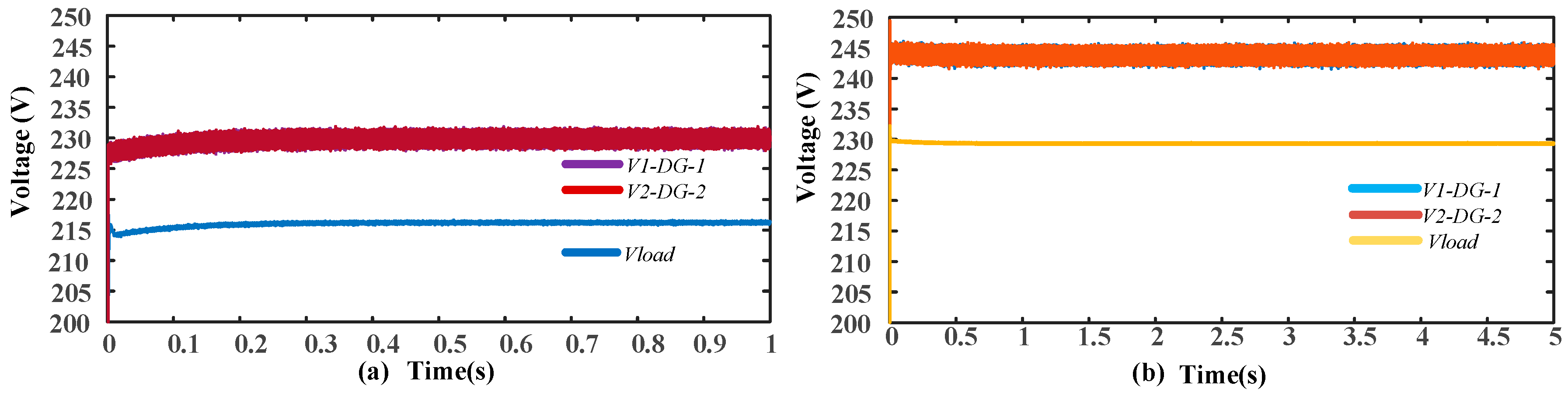
Figure 7.
(a) Active power for the conventional control strategy; (b) active power for proposed control strategy.
Figure 7.
(a) Active power for the conventional control strategy; (b) active power for proposed control strategy.

Figure 8.
(a) Reactive power for the conventional control strategy; (b) reactive power for proposed control strategy.
Figure 8.
(a) Reactive power for the conventional control strategy; (b) reactive power for proposed control strategy.

Figure 9.
(a) Inverter terminal and load voltages for the conventional control strategy; (b) inverter terminal and load voltages for proposed control strategy.
Figure 9.
(a) Inverter terminal and load voltages for the conventional control strategy; (b) inverter terminal and load voltages for proposed control strategy.

Figure 10.
(a) Active power for the conventional control strategy; (b) active power for proposed control strategy.
Figure 10.
(a) Active power for the conventional control strategy; (b) active power for proposed control strategy.

Figure 11.
(a) Reactive power for the conventional control strategy; (b) reactive power for proposed control strategy.
Figure 11.
(a) Reactive power for the conventional control strategy; (b) reactive power for proposed control strategy.

Figure 12.
(a) Inverter terminal and load voltages for the conventional control strategy; (b) inverter terminal and load voltages for the proposed control strategy.
Figure 12.
(a) Inverter terminal and load voltages for the conventional control strategy; (b) inverter terminal and load voltages for the proposed control strategy.

Figure 13.
(a) Active power for the conventional control strategy; (b) active power for proposed control strategy.
Figure 13.
(a) Active power for the conventional control strategy; (b) active power for proposed control strategy.

Figure 14.
(a) Reactive power for the conventional control strategy; (b) reactive power for proposed control strategy.
Figure 14.
(a) Reactive power for the conventional control strategy; (b) reactive power for proposed control strategy.

Figure 15.
(a) Inverter terminal and load voltages for the conventional control scheme; (b) inverter terminal and load voltages for proposed control scheme.
Figure 15.
(a) Inverter terminal and load voltages for the conventional control scheme; (b) inverter terminal and load voltages for proposed control scheme.

Figure 16.
(a) Active power for the conventional control scheme; (b) active power for proposed control scheme.
Figure 16.
(a) Active power for the conventional control scheme; (b) active power for proposed control scheme.

Figure 17.
(a) Reactive power for the conventional control scheme; (b) reactive power for proposed control.
Figure 17.
(a) Reactive power for the conventional control scheme; (b) reactive power for proposed control.

Figure 18.
Frequency regulation.


Table 1.
Typical line impedance values.
| Types of Line | R (Ω/km) | X (Ω/km) | R/X |
|---|---|---|---|
| Low voltage line | 0.642 | 0.083 | 7.7 |
| Medium voltage line | 0.161 | 0.190 | 0.85 |
| High voltage line | 0.06 | 0.191 | 0.31 |
Table 2.
System and controller parameters.
| Parameter | Symbol | Value |
|---|---|---|
| Nominal frequency | f* | 50 Hz |
| Nominal voltage | V* | 230 V |
| Switching frequency | fs | 16 KHz |
| Ratings of each DG unit | VA | 60 KVA |
| dc voltage | Vdc | 700 V |
| Voltage loop | Kpv, Kiv | 20, 50 |
| Current loop | KpI, KiI | 40, 100 |
| Frequency droop | mP1, mP2 | 0.0034 rad/w |
| Voltage droop | nQ1, nQ2 | 0.001 rad/w |
| Equal line impedances | Line 1, Line 2 | 0.05 + j1.099 Ω |
| Unequal line impedance | Line 1, Line 2 | 0.05 + j1.099 Ω, 0.05 + j1.3 Ω |
© 2018 by the authors. Licensee MDPI, Basel, Switzerland. This article is an open access article distributed under the terms and conditions of the Creative Commons Attribution (CC BY) license (http://creativecommons.org/licenses/by/4.0/).
Share and Cite
MDPI and ACS Style
Khan, M.Z.; Khan, M.M.; Jiang, H.; Hashmi, K.; Shahid, M.U. An Improved Control Strategy for Three-Phase Power Inverters in Islanded AC Microgrids. Inventions 2018, 3, 47. https://doi.org/10.3390/inventions3030047
AMA Style
Khan MZ, Khan MM, Jiang H, Hashmi K, Shahid MU. An Improved Control Strategy for Three-Phase Power Inverters in Islanded AC Microgrids. Inventions. 2018; 3(3):47. https://doi.org/10.3390/inventions3030047
Chicago/Turabian StyleKhan, Muhammad Zahid, Muhammad Mansoor Khan, Huawei Jiang, Khurram Hashmi, and Muhammad Umair Shahid. 2018. "An Improved Control Strategy for Three-Phase Power Inverters in Islanded AC Microgrids" Inventions 3, no. 3: 47. https://doi.org/10.3390/inventions3030047