
Open-Source Designs for Distributed Manufacturing of Low-Cost Customized Walkers


1
Thompson Centre for Engineering Leadership and Innovation, Western University, London, ON N6G 0N1, Canada
2
Department of Electrical & Computer Engineering, Ivey Business School, Western University, London, ON N6A 5B9, Canada
*
Author to whom correspondence should be addressed.
Inventions 2023, 8(3), 79; https://doi.org/10.3390/inventions8030079
Submission received: 25 April 2023
/
Revised: 27 May 2023
/
Accepted: 31 May 2023
/
Published: 5 June 2023
(This article belongs to the Collection Feature Innovation Papers)
Abstract
:To improve accessibility, this article describes a static, four-legged walker that can be constructed from materials and fasteners commonly available from hardware stores coupled by open-source 3D-printed joints. The designs are described in detail, shared under an open-source license, and fabricated with a low-cost open-source desktop 3D printer and hand tools. The resulting device is loaded to failure to determine the maximum load that the design can safely support in both vertical and horizontal failure modes. The experimental results showed that the average vertical failure load capacity was 3680 ± 694.3 N, equivalent to 375.3 ± 70.8 kg of applied weight with the fractured location at the wood dowel handlebars. The average horizontal load capacity was 315.6 ± 49.4 N, equivalent to 32.2 ± 5.1 kg. The maximum weight capacity of a user of 187.1 ± 29.3 kg was obtained, which indicates that the open-source walker design can withstand the weight requirements of all genders with a 95% confidence interval that includes a safety factor of 1.8 when considering the lowest deviation weight capacity. The design has a cost at the bottom of the range of commercial walkers and reduces the mass compared to a commercial walker by 0.5 kg (19% reduction). It can be concluded that this open-source walker design can aid accessibility in low-resource settings.
1. Introduction
More than 10% of the adult public live with mobility-related disabilities [1,2]. The physical struggles of accomplishing many activities of daily living are exacerbated further for those with limited financial resources, whether living in less developed countries or seniors living in poverty [3]. There are adaptive mobility aids available on the market to help (e.g., canes, walkers, rollators, wheelchairs, etc.). Unfortunately, not everyone has easy access to the global market [4], financial support can vary considerably across jurisdictions, and the additional monetary strain to purchase all the necessary adaptive aids can limit an individual’s ability to remain independent. As an example, proprietary commercial walkers range in price from CAD 66 to CAD 130 [5]. Those with mobility disabilities and living on restricted fixed incomes would benefit financially from price relief for adaptive aids. This is the case even for those with health insurance or living in a country with universal medical coverage, as the device may not be covered by their health insurance and may need to be paid out of pocket. Similarly, those without access to commercial mobility aids would benefit from a means to have them manufactured locally.
The prevalence of mobility disabilities increases as people age and develop age-related conditions such as arthritis, back problems, chronic conditions, and accidental injuries [6]. A substantial portion of the elderly population is known to be living in financial hardship, with 10.3% of U.S. adults ages 65 and older living in poverty as of 2021 [7]. In addition, the American population is aging and by 2060, approximately a quarter of Americans will be 65 years or older [8]. This will exacerbate the current challenge and thus there is a clear need for more cost-effective adaptive mobility aids.
An approach that is gaining momentum to reduce the cost of consumer goods is the digital distributed manufacturing of components and products with CNC tools such as 3D printers [9,10,11]. Briefly, 3D printers have evolved from rapid prototypers into additive manufacturing (AM) devices that can be operated by local businesses [12,13,14], chain stores (e.g., shipping firms such as UPS or government-owned mail [15] and home improvement retailers [16]), makerspaces [17,18,19], fablabs [20], and libraries [21,22,23]. A particularly enriching approach is the do-it-together paradigm [24], where companies share open-source designs and manufacture locally [25,26]. This widespread use of 3D printing is already poised to disrupt global value chains [27].
The migration of open-source technical development originally modeled in software [28] has also matured in hardware development: free and open-source hardware (FOSH) development [29,30]. FOSH has been growing exponentially [31] in large part due to FOSH development decreasing the costs of 3D printers [32]. This was made possible by the open-source release of self-replicating rapid prototyper (RepRap) designs (e.g., 3D printers that can 3D print now more than half of their own components) [33,34,35]. There are millions of 3D printable FOSH designs [36], and as people can treat 3D printers as a profitable investment for household-level distributed manufacturing [37,38], there is evidence that this method is saving consumers millions of dollars per year [39].
The same open-hardware approach used for general consumer items can be applied to adaptive aids. For example, using this model for adaptive arthritis aids has resulted in financial savings averaging over 94% compared to those with commercially available products [40]. Organizations such as Makers Making Change [41] have begun using this model as they connect people with disabilities that need assistive technologies with makers, to design and fabricate the aids [42]. Where such a model is perhaps most powerful is when an open-source design can be customized for a particular person, which increases the value for the person while possibly reducing the overall costs.
In a recent review of adaptive aids for disabilities [43], although there were several open-source solutions for those in wheelchairs in the mobility disability section, there were no good options for those that require walkers. Walkers can be categorized into three main groups: standard static walkers, front-wheeled walkers, and rollators. Standard static walkers provide the greatest weight bearing and require the user to completely lift the device off the ground for each step. This could pose a challenge for those with reduced upper body strength. Front-wheeled walkers overcome this problem and resemble standard walkers with wheels attached at the bottom of the two front legs, allowing the user to sustain a more natural gait pattern. Rollators have four wheels, a braking system, and a seat component that is better suited for users that require less weight bearing [44]. Accordingly, there is a need to establish an initial walker design that can then be evolved through open-source collaboration to address low-income mobility needs.
This article reports on the mechanical testing needed to develop a low-cost static walker under the open-source model. A functional standard walker design is described, fabricated, and tested. The resulting device is a static, four-legged, walker that can be constructed from member materials and fasteners commonly available from hardware stores coupled by open-source 3D-printed joints. The aggregate walker is loaded to failure to determine the maximum load that the design can safely support in both vertical and horizontal failure modes. The experimental results are evaluated to determine the potential for distributed digital manufacturing to assist individuals living with mobility limitations and conclusions are drawn.
2. Materials and Methods
2.1. Walker Design
Upon reviewing several commercially available walkers, the initial concept for an open-source walker was designed with 3D-printed joints and standard wooden dowels using Onshape CAD software (Onshape 1.157, Cambridge, MA, USA). The Onshape file is publicly shared [45] and the full design including the bill of materials (BOM), CAD, STL and spreadsheets are available under a GNU GPL v3 license on the Open Science Framework [46]. Solid, circular cross-sectional wooden dowels were chosen as the main structural members for their sustainability characteristics, as well as their general availability in standard sizes at hardware stores throughout North America. In addition, wood is a renewable resource that can be recycled and composted. A study comparing the carbon footprint of wood, and aluminum, a common structural member material for mobility aids, in the context of window frames, shows that wood produced approximately four times less carbon footprint than aluminum did [47]. Though strength will vary depending on the exact hardwood (e.g., basswood, beech, maple, oak, etc.) or softwood (e.g., cedar, pine, spruce, etc.) chosen [48], the initial design was constructed using relatively lower strength basswood, to assess the design conservatively.
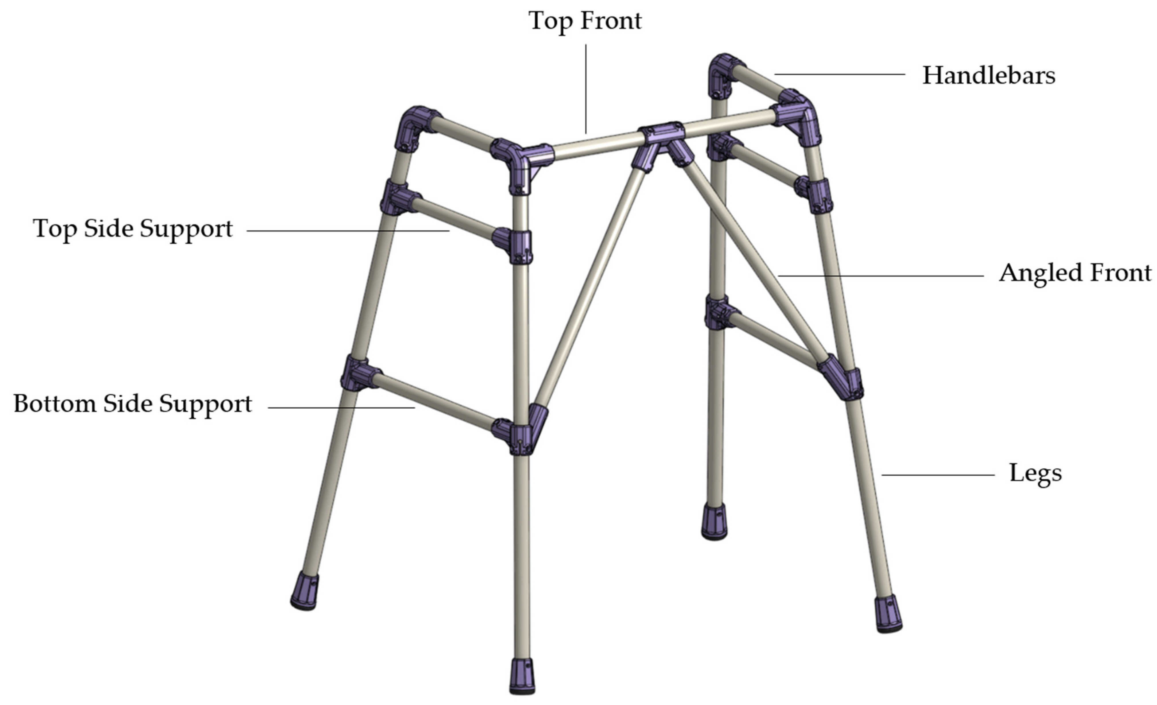
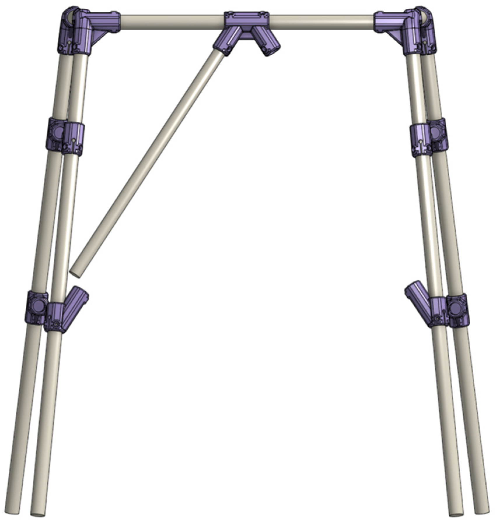
The open-source, four-legged, static walker 3D-rendered design is shown in Appendix A and includes several features that were derived from reviewing commercially available devices. The front of the walker employs a triangular bracing structure that angles inwards from the front legs and meets centrally on the top bar. This provides structural rigidity, while not interfering with a user’s legs if the walker is positioned in front of them during a sit-to-stand movement. The sides of the walker also feature two horizontal members to improve the rigidity of the device. Additionally, an A-frame design was selected to improve the stability of the walker frame. To create this effect, the front and back legs of the walker are angled 10° forward and backward, respectively, while the sides are angled outward at 5°.
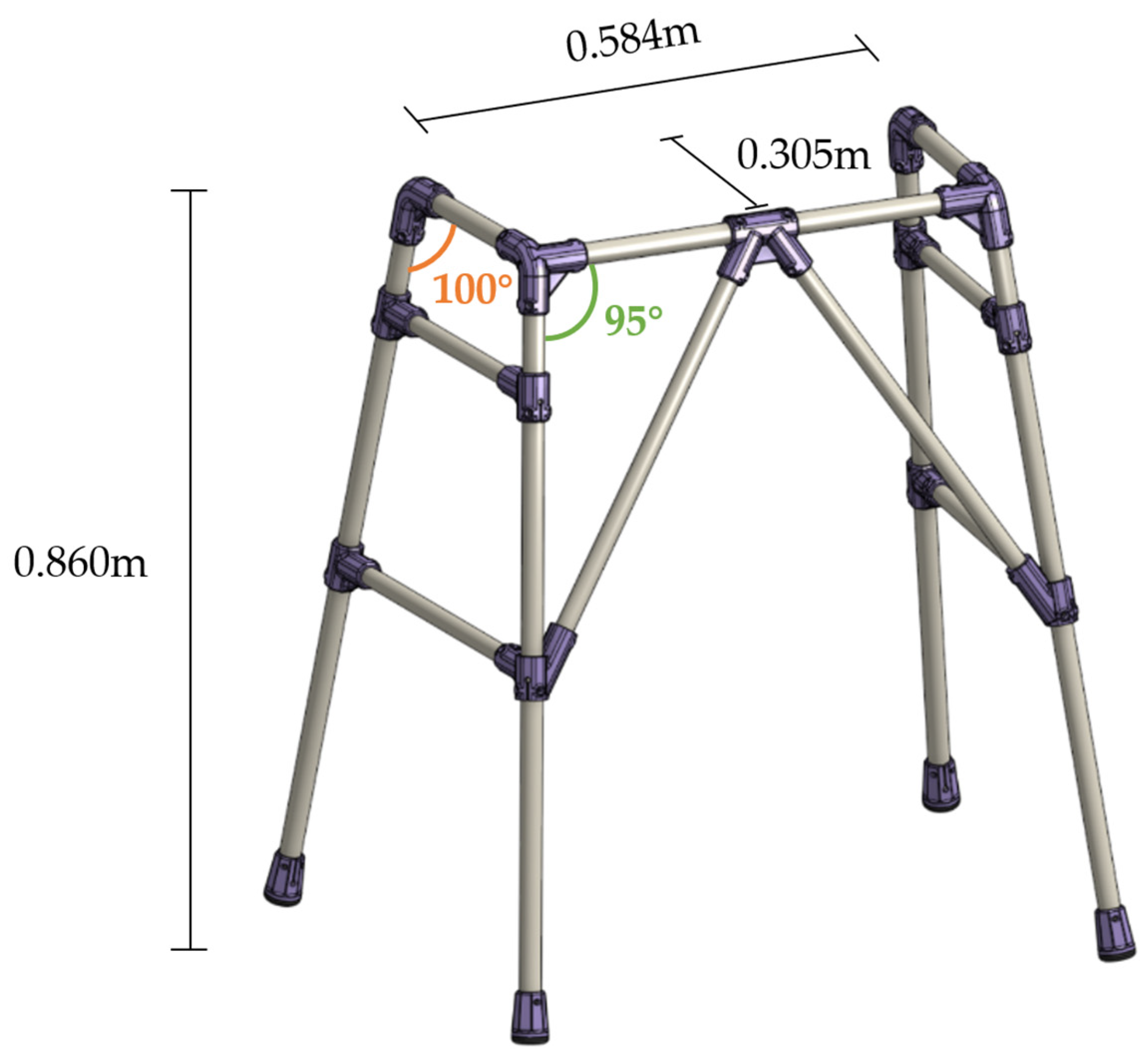
In its tested form (Figure 1), the walker measures 0.860 m tall from the floor to the top of the handles, 0.580 m wide from left to right at the handles, and 0.305 m deep from front to back (or 0.622 m measured at the bottom of the legs). This initial version of the walker was designed with the intention that the wooden dowels would be cut to length to fit an individual, and as such, the walker size is not currently adjustable without replacing the wooden dowels. The present embodiment was sized for an adult 1.65 m tall according to the instructions provided in Appendix A. To ensure a smooth but snug fit of the 3D-printed parts onto the wood dowels, a diameter tolerance of 0.6 mm was used for all connector and support parts.
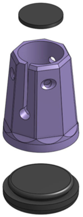
Additionally, the walker features a three-piece foot design that connects a thermoplastic polyurethane (TPU) base to the wooden dowels via a press-fit polyethylene terephthalate glycol (PETG) body and #6 flathead screws. These dual material feet provide greater frictional resistance to improve walker stability when used on smooth surfaces, such as wooden or tiled floors. A convex cylindrical TPU handle can also be press-fit centrally on the top of the walker sides to improve the grip and comfort for the user.
2.2. Overview of 3D Printing
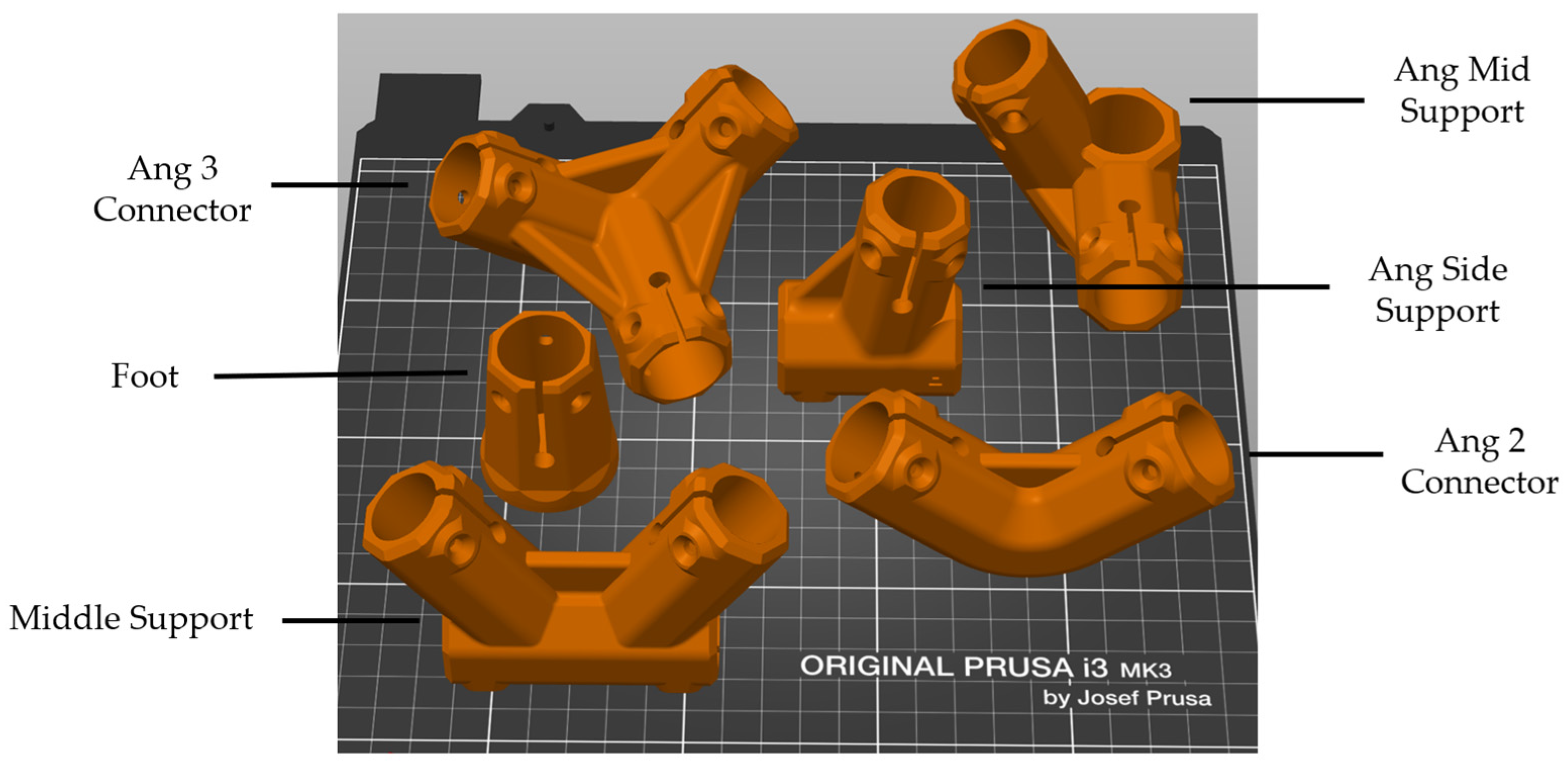
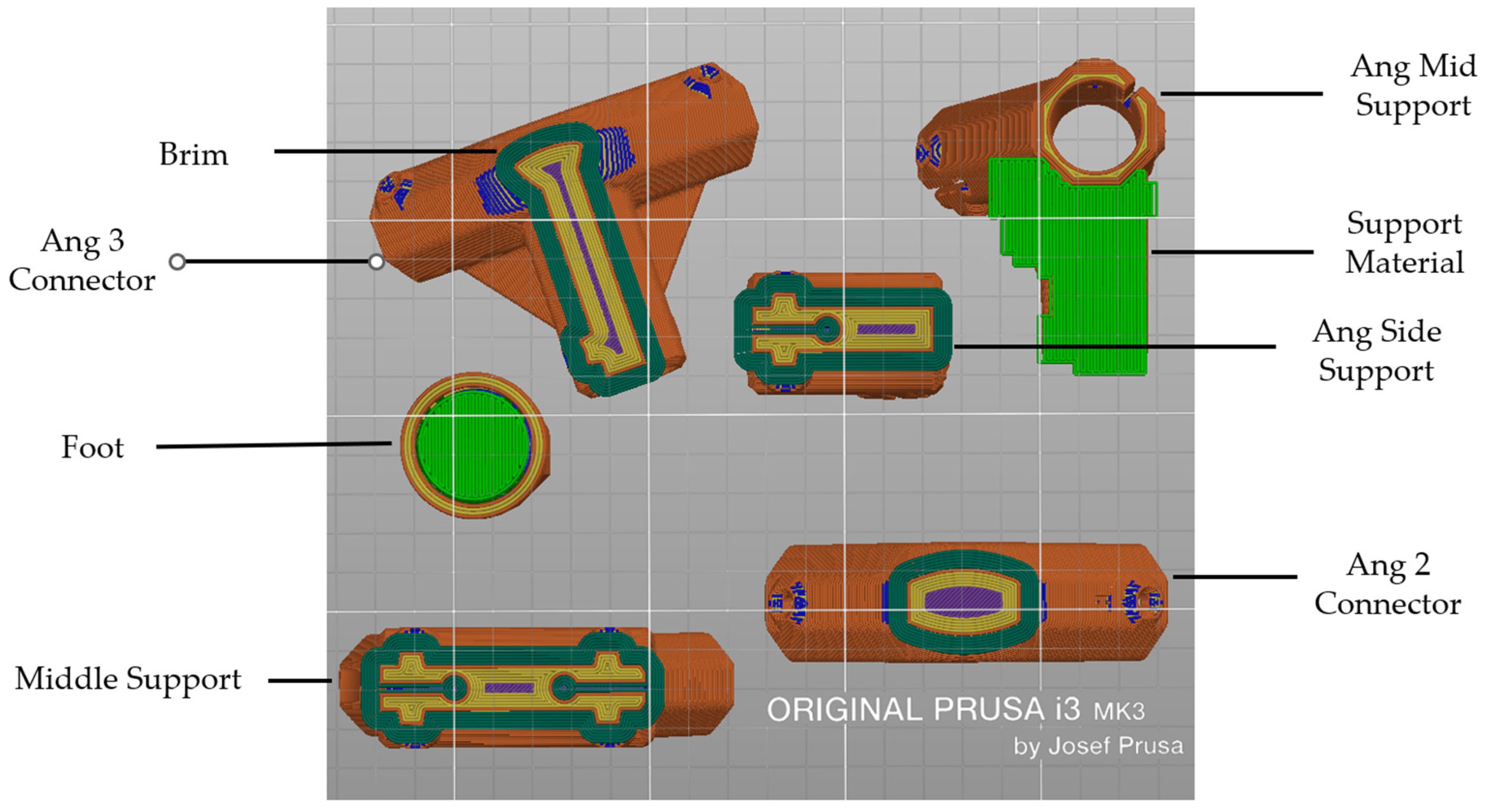
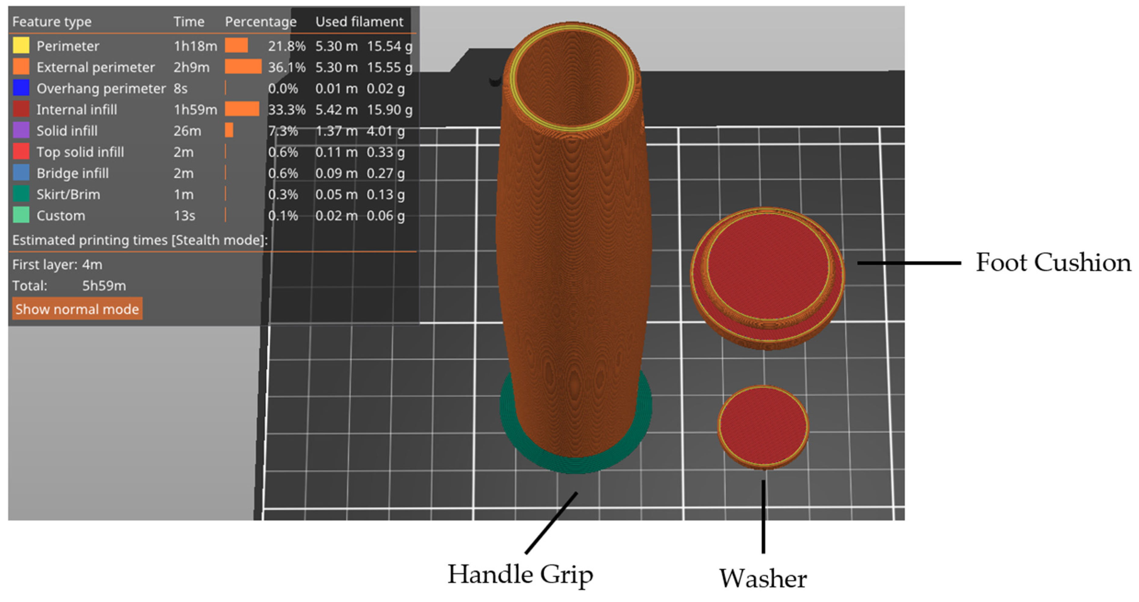
All 3D-printed parts were created using either a Polymaker PETG filament [49] or Ninja Flex TPU [50] printed on an open-source RepRap-class 3D printer: Prusa i3 Mk3S (Prusa, Prague, Czech Republic) using a 0.8 mm nozzle. Table 1 lists the names and quantities of the 3D-printed parts and Table 2 provides the slicing parameters of for the PETG and TPU components. Due to the intricate shapes of the parts, each was oriented strategically on the print bed to avoid aligning the print layers with the anticipated fracture failure planes (Figure 2). A brim of 0.5 mm is recommended for parts with minimal surface contact with the bed, while Support is required for both the Ang Mid Supports and the Foot Body components due to extreme overhangs; see Figure 3 for 3D-printed parts with support locations and brim. Finally, the handle was printed in a vertical orientation, as shown in Figure 4.
2.3. Wood Dowel Part Sizing
To ensure the walker is made to the proper fit for the user, measurements should be taken and adjusted with the calculation procedures detailed below. The quantity of each dowel part is specified in Table 3 along with a labeled diagram of the wood dowel components and sample calculations in Appendix A and Appendix B, respectively.
- Height of the walker: measure from the ground to the crease of the user’s wrist while in an upright position with arms relaxed on the sides and wearing shoes.
- Length of the walker leg dowels: Take the height of walker established above and divide by Cosine(10°). Subtract 15 mm for the thickness of the foot cushion and 30.75 mm for the top 3D dowel joint. The final value is the length at which four wood dowels should be cut as the legs of the walker.
- Width of the walker: Standard walkers have a width between 635–735 mm. However, if the user requires going through more narrow entryways, some walkers can also be between 560–610 mm [51]. For a more comfortable fit, it is recommended that the walker is slightly larger than shoulder width or more if the user has a wider stride.
- Length of the top front dowel to be cut: subtract 35.5 mm from the width of walker value established above.
- Depth of the walker: Proper depth allows the user’s hands to fit comfortably and within the handle and is dependent of the handle length. Ensure the length is larger than the width of the user’s fist, and the amount of extra handle grip is determined by the preference of user.
- Length of the handlebar dowel to be cut: add 82 mm to the length of the handle.
- Length of the angled front dowel: Perform sine law by dividing the calculated length of the top front dowel by 2, subtract 12 mm, multiply by Sine (95.296°), and then divide by Sine (27.404°). Finally, subtract 75 mm.
- Length of side dowels: These will be the last dowels cut as dimensions are dependent on the slight variations during construction and therefore the walker would have to be almost fully constructed. The length will be measured once the Ang Side connectors are placed in the proper locations as specified in the assembly instructions in Appendix B between steps 15, 16 and 17. The measurement is taken from one end of the circular stress reliever to the other and then 9 mm will be added to that value.
Table 3 summarizes the wood dowel parts required to construct a personalized walker along with the quantity.
See Appendix B for detailed assembly instructions and images.
2.4. Walker Mechanical Testing
To ensure the walker assembly can safely withstand regular use, mechanical testing was conducted to find the maximum load required to fracture the device in the vertical and horizontal planes. The following methods were conceived to mimic and exceed the “static strength of walking frame” testing described in Section 16.1 of ISO 11199-1 2021. This standard requires walkers to bear a purely vertical load of 1500 N without cracking or breaking for a duration of 2 to 5 s [52]. To provide additional design insights regarding failure modes and locations, our methods exceed this standard by testing the walkers to failure. For each test, 5 trials were recorded using a load cell (1210AF-1K-B 1000lb, Interface, Scottsdale, AZ, USA), a potentiometer-style displacement gauge (TR100, Novotechnik, Southborough, MA, USA) with a 100 mm range, and a custom LabVIEW control program (National Instruments, Austin, TX, USA). For each of the following assessments, force–displacement curves were recorded and analyzed in a spreadsheet to determine the maximum load the walker could withstand before failure. Failure was defined as the point at which the applied force began to decrease with continued displacement, which coincided with the fracturing of either the wooden dowels or the 3D-printed components. In addition, each of the trials on the force–displacement curve will indicate the stiffness in Newtons per millimeter (N/mm), which is calculated by inserting a trendline to quantify the slope of the flat region of the force-displacement curves.
For the vertical testing, a universal compressive and tensile testing machine (Tinius Olsen, Horsham, PA, USA) capable of uniaxial compression was used to apply a manually controlled vertical force to the walker and distributed across the center of the top handlebars. The vertical load was applied at a rate of 0.18 ± 0.4 mm/s, and was captured with a resolution of 100 N. The walker was placed freely within the testing machine with its TPU feet in contact with the base of the test machine to mimic the static strength testing of ISO 11199-1 2021. None of the tested walkers experienced moving or sliding when load was applied. The load application points were positioned to cover the areas of a typical span of a fist to simulate the vertical component of force applied by the user pushing down onto the walker with their hands, also in-keeping with the relevant ISO standard (shown in Figure 5).
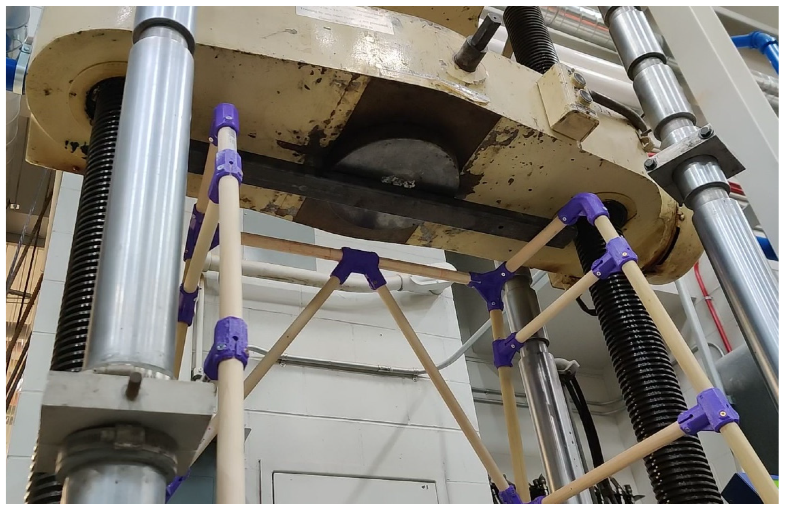
To test horizontal failure, an Enerpac single-action manual hydraulic hand pump (P39, Enerpac, Menomonee Falls, WI, USA) and a Simplex single-acting hydraulic cylinder (R106, 2-ton capacity, Simplex, Broadview, IL, USA) were used to apply an expanding force to the walker handlebar from the inside of the device until component failure occurred. Again, load application was increased manually by a single technician at a measured rate of 0.90 ± 0.31 mm/s. The walker was placed freely on the floor surface and allowed to deflect horizontally. See Figure 6 for a layout of the testing equipment. This force was intended to simulate the outward horizontal force components the walker may experience from a normal user-applied load (shown as FH in Figure 7). For both vertical and horizontal testing, the force was controlled manually by a single operator to maintain consistency across trials.
2.5. Calculating Body Weight Capacity
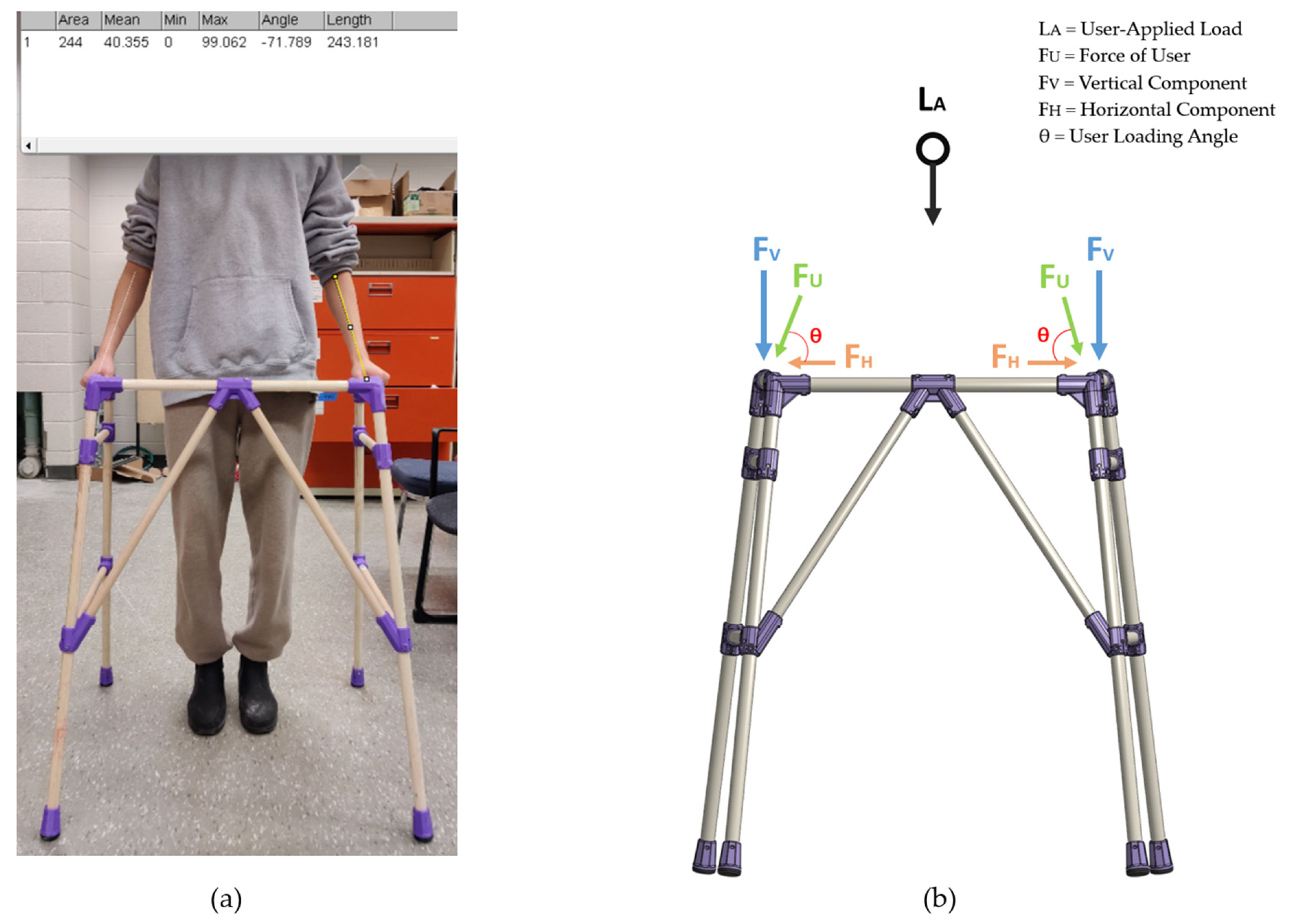
To represent the vertical and horizontal failure modes in more meaningful terms, the forces measured were translated into the amount of user-applied load the current design is capable of supporting. To calculate this, the force exerted by the user’s arms is broken down in its vertical (i.e., FV) and horizontal (i.e., FH) components. To carry this out, the angle created between the forearm and horizontal plane was measured using ImageJ, an open-source image processing software [53], while the user positioned their arms resting on the walker (see Figure 7).
Through trigonometric relationships, the vertical and horizontal capacities of the device can be related to user-applied load (i.e., LA) by assuming an even distribution across the two handlebars and balancing the vertical forces (i.e., LA = 2FV). The arm force, FU, is applied at an angle of θ from the horizontal plane, and is deconstructed into its vertical and horizontal force components.
Accordingly, the user-applied load limit for vertical component corresponding to failure can be calculated from the vertical capacity as follows:
Similarly, from the horizontal component, the user-applied load limit can be determined by Equations (2) and (3):
where, FTestVertical and FTestHorizontal are the measured vertical and horizontal capacities of the walker, respectively.
3. Results
3.1. Orientation of User-Applied Load
Analysis of the frontal plane image of the sample user indicated that the angle between their forearm and the horizontal bar of the walker was 71° (Figure 7). Accordingly, Equations (1)–(3) are for calculating the limits of user-applied load for vertical and horizontal capacity testing.
3.2. Vertical Walker Testing
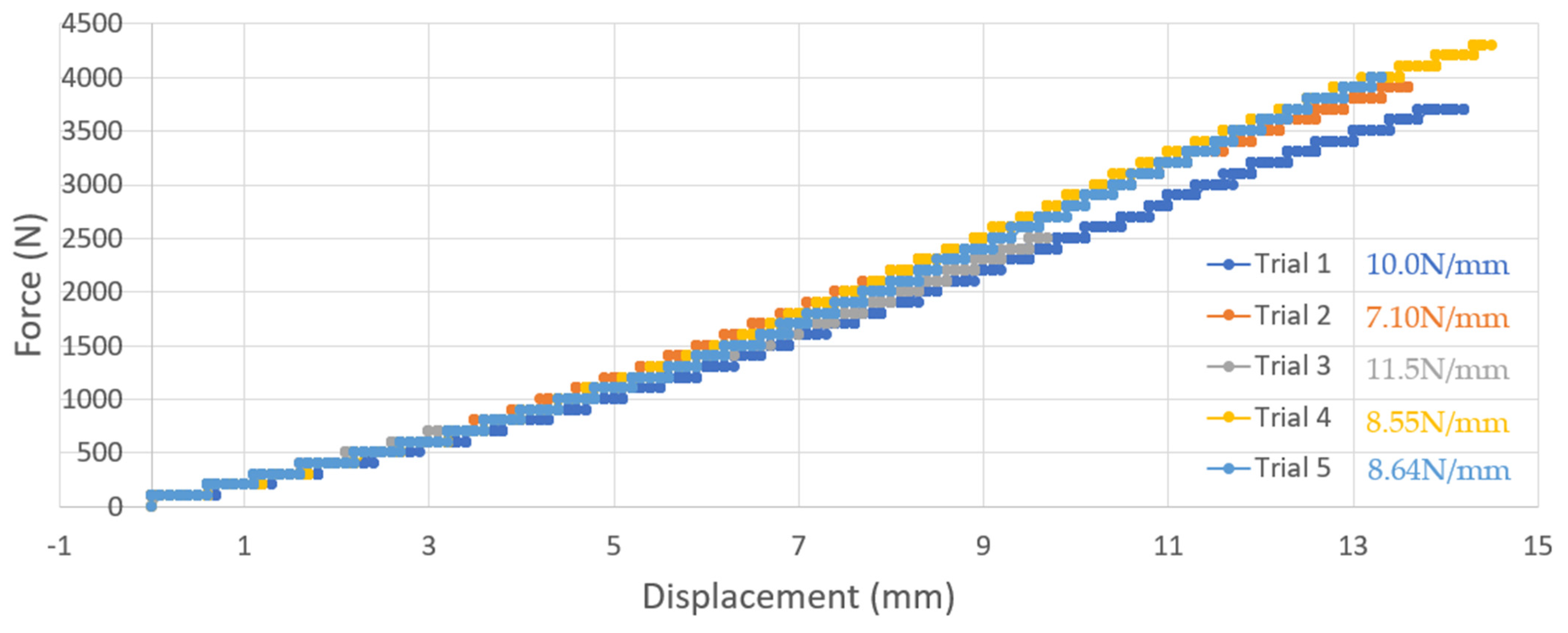
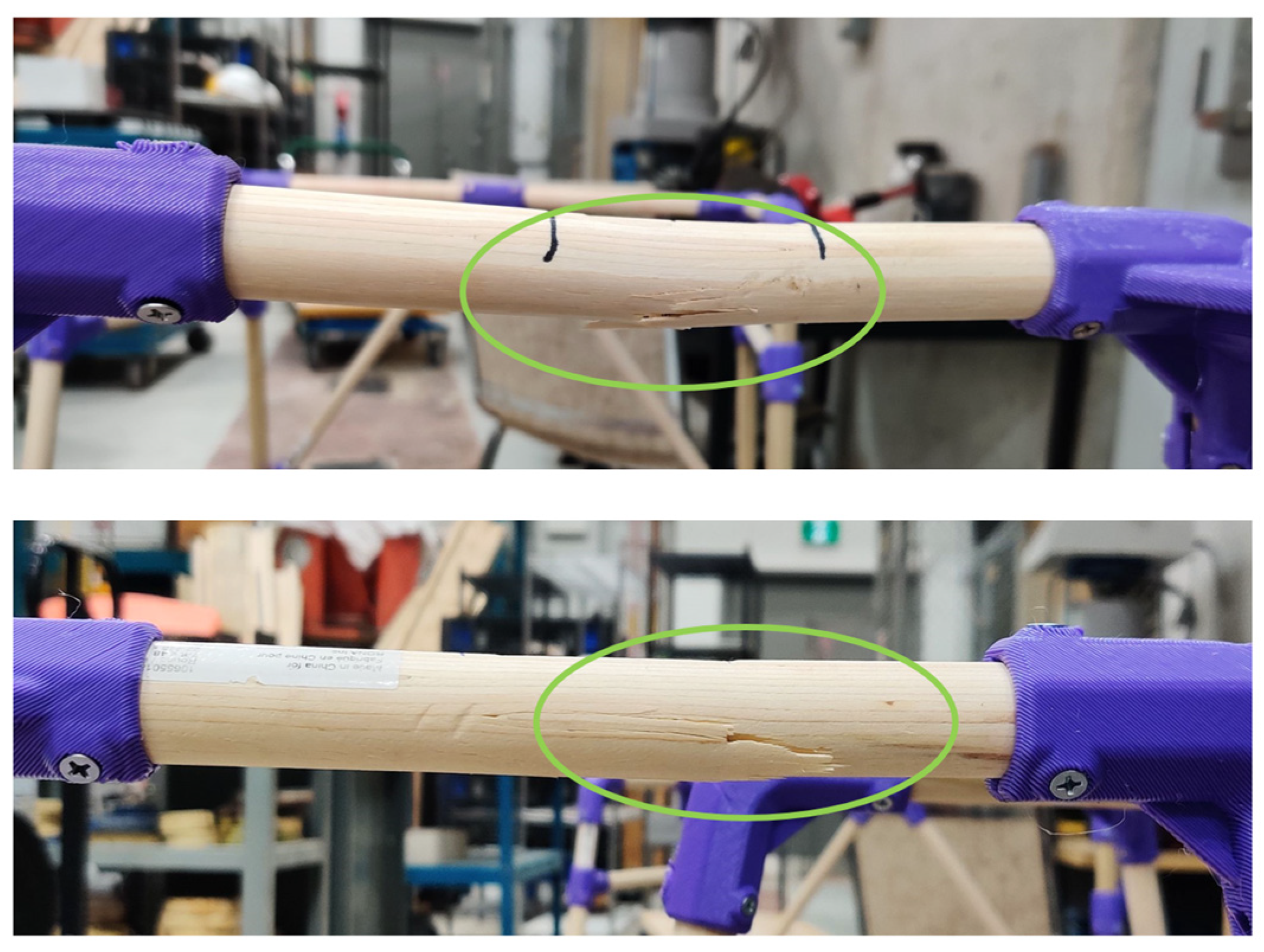
The failure load corresponding with the vertical capacity of the walker ranged between 2500 N and 4300 N with an average of 3680 ± 694.3 N (see Figure 8). These failure loads were the result for vertical displacements ranging from 9.7–14.5 mm, or an average of 13.1 ± 1.94 mm. The load to failure of trial 3 was the lowest, and is expected to have resulted from an imbalance of vertical load distribution across the walker handles, which was noted at the time of testing. All the walkers’ failure points under vertical loading were found to be at the handlebars (as shown in Figure 9) where the wood dowels fractured. Additionally, three out of five of the walkers exhibited very slight surface cracks on other wooden dowels located along the leg dowels. All 3D-printed parts remained intact. Using Equation (1), the user-applied load associated with this vertical failure mode was calculated to be 375.3 ± 70.8 kg.
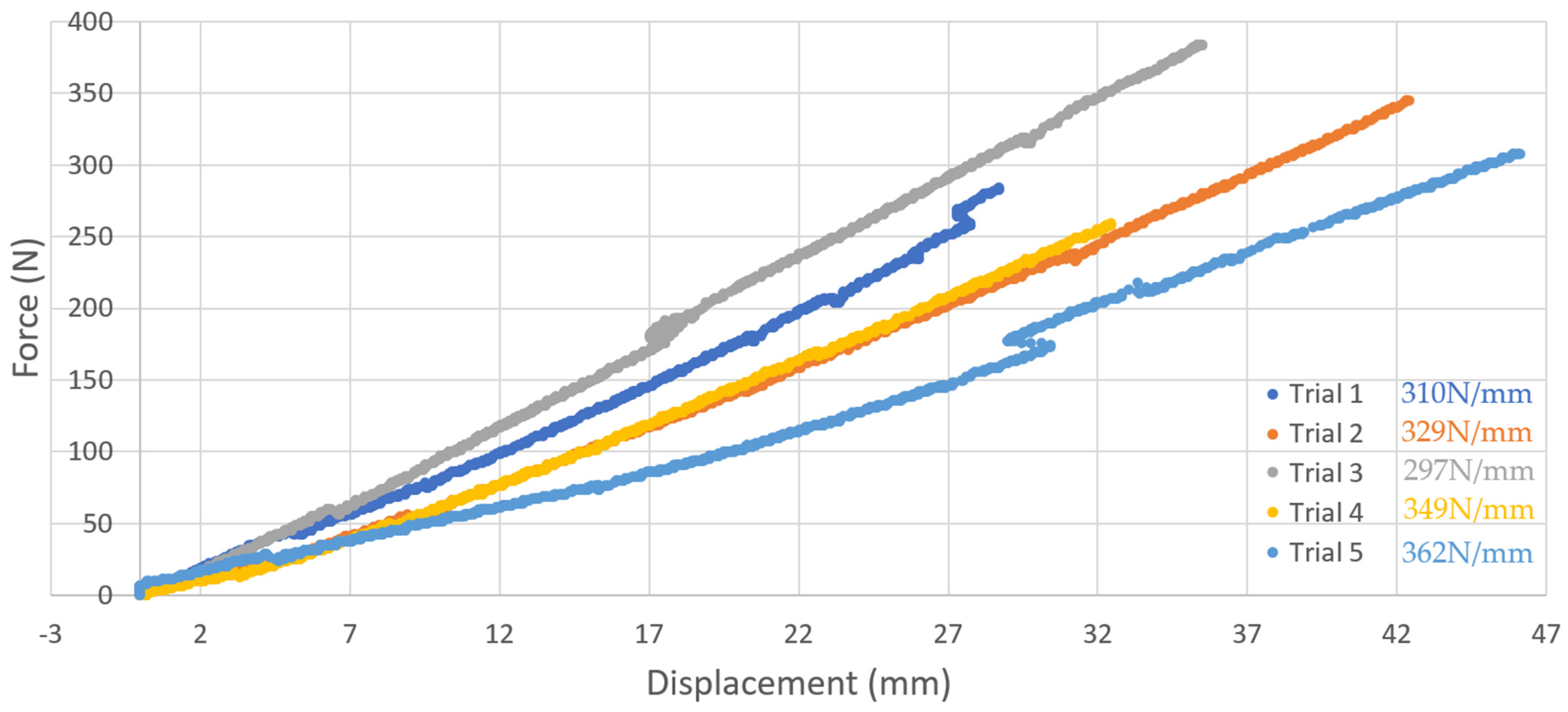
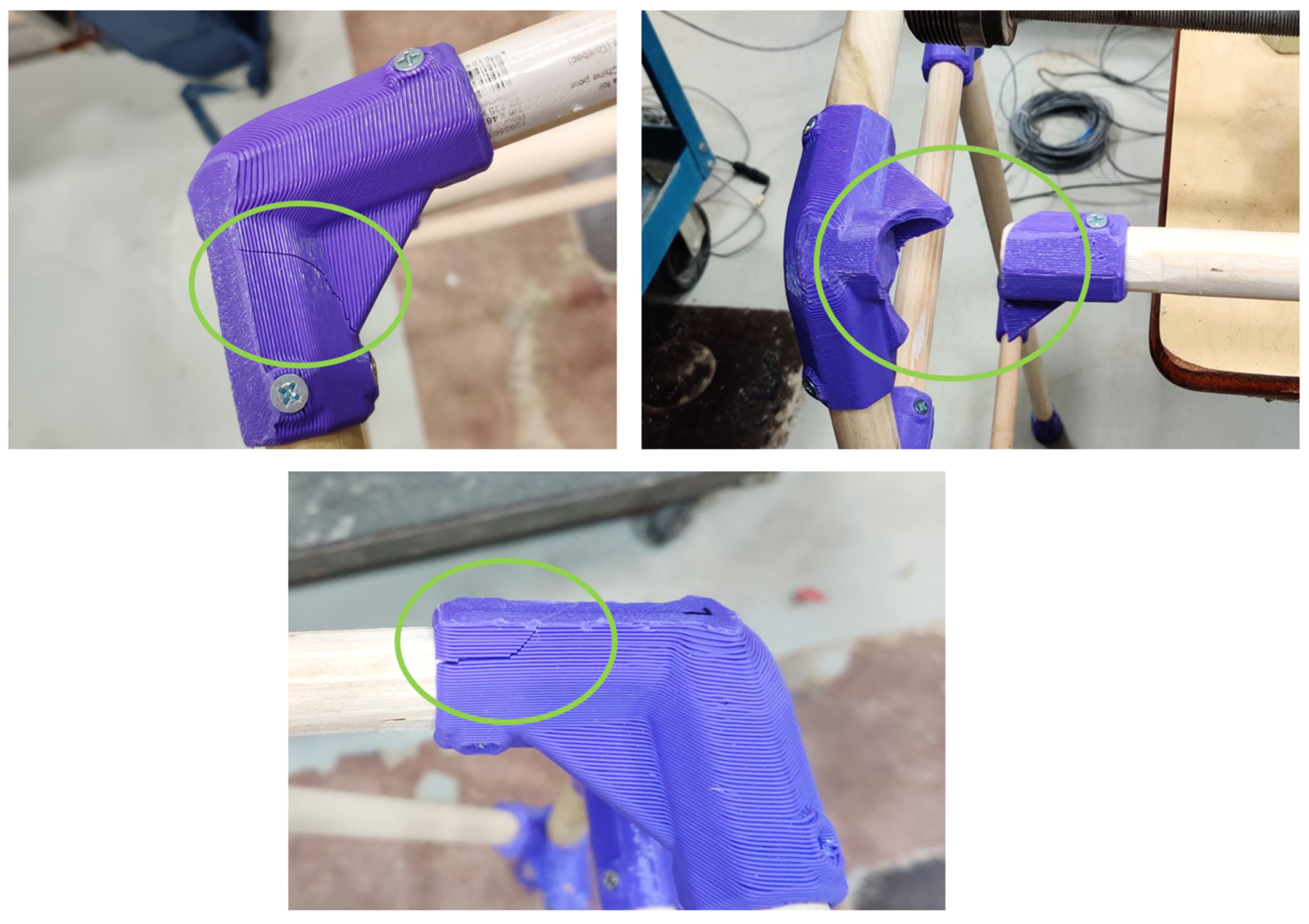
3.3. Horizontal Walker Testing
The failure load corresponding to the horizontal capacity of the walker ranged from 259 N to 384 N, with the average being 315.8 ± 49.4 N (see Figure 10). These failure loads were the result for horizontal displacements ranging from 28.7–46.1 mm, or an average of 37.0 ± 7.15 mm. For the horizontal testing, failure consistently manifested at the Ang 3 Connector 3D-printed part, where it experienced splitting and cracking, as shown in Figure 11. All wooden dowels and the rest of the 3D-printed parts remained unaffected. Using Equation (2), the horizontal capacity of the user-applied load that would yield this horizontal failure was calculated to be 32.2 ± 5.1 kg. It should be noted that Figure 10 from horizontal testing may appear to have a higher variability in results due to the much smaller scale of the y axis relating to force in a range up to 400 N compared to that in Figure 11 from vertical testing that displays data in a range up to 4500 N. The proportions of standard deviations to their average values for both testing types, however, are similar and in fact the variation in the vertical test is slightly higher.
4. Discussion
4.1. Calculating Weight Capacity of Walker
The user-applied load limit was found to be much larger for vertical failure (3680 ± 694.3 N, or 375.3 ± 70.8 kg) as opposed to horizontal failure (315.8 ± 49.4 N, or 32.3 ± 5.04 kg). This indicates that the current design of the static walker is limited by a horizontal failure mode that would result in the fracturing of the 3D-printed Ang 3 Connector to occur first. Should additional load-bearing capacity be required, future iterations of the walker should begin with redesigning this component.
According to Statistics Canada, in 2009 the mean weight of Canadian men and women was 86.4 kg and 72.1 kg, respectively [54]. These weights are far below the measured failure load limit of the walker, with safety factors of 1.82 and 2.19 for men and women, respectively. Furthermore, the current walker design would be expected to have a safety factor of 2 for bearing all of the bodyweight of individuals that weigh 78.9 kg. It should be noted that this failure load analysis is not without limitations. The vertical and horizontal capacities of the walker were assessed by independently applying forces to the device in each direction, and at relatively slow rates. It is possible that the combined loading of the walker in three dimensions could yield an alternative failure mode with a lower limit. The walker was also tested under an idealized use case, where the user was operating the device with two hands and evenly applying load to both handlebars and all four legs in contact with the ground. Again, deviations from these boundary conditions may yield alternative failure modes and limits. Finally, the results indicated here are specific to the construction described in Section 2. The walker’s dimensions, member material, and 3D-printed part construction should all be expected to change the load limits of the static walker. Despite these limitations, the safety factors described above are promising, and suggest that the device should be capable of safely bearing the load of individuals whose bodyweight is between the ranges of 78.9 to 93.55 kg during normal operating conditions.
Though the deflections reported for load-to-failure are large for both vertical and horizontal failure modes (vertical: 13.1 ± 1.94 mm, horizontal: 37.0 ± 7.15 mm), it is important to consider how much deflection is expected to occur under typical use conditions to assess user comfort. A user-applied load corresponding to 100 kg of fully supported bodyweight would be expected to yield vertical and horizontal testing loads of 981 N and 162 N according to Equations (1) and (3). From Figure 8 and Figure 10, the corresponding vertical and horizontal deflections are 4.42 ± 0.18 mm and 21.6 ± 4.83 mm, respectively. This vertical deflection seems reasonable given that the walker uses soft TPU feet to dampen impacts with the ground. The horizontal deflection may be of more concern; however, it is important to consider that the walker is not typically exposed to full bodyweight, and this displacement occurred without the influence of bodyweight-induced ground friction to counteract leg expansion during the isolated horizontal testing. Future designs may wish to consider the use of additional bracing to limit horizontal deflection.
4.2. Benefits of the Open-Source Walker
The open-source walker has several benefits. First, it can be customized for the user, so that the additional mass and unneeded complexity of a multi-height walker is eliminated. This results in substantial mass savings with typical walkers weighing 2.7 kg compared to this open-source design, which weighs 2.2 kg [55]. A 19% reduction in weight can have significant impacts on the users since static walkers require frequent use of upper body strength to lift the device each time it is moved. This reduced weight is particularly beneficial for those with limited strength, mobility, and balance. Device weight calculations are presented in Appendix C. Second, the open-source walker has potential for an aesthetic benefit, as users can customize the walker both with paint or stain on the wood as well as the color, texture and design on the 3D-printed parts. Additionally, the total cost of the open-source walker as designed and tested here is CAD 86.97 using commercial PETG/TPU and CAD 65.52 using Recyclebot PETG/TPU in contrast with the price of CAD 66–130 of standard commercial walkers. The range of the open-source walker’s cost is overall lower than that of current walker purchasing options. The cost, bill of materials, and comparisons between purchasing in the U.S. or Canada is shown in Appendix C.
The largest benefit of an open-source walker design may be its accessibility. Different geographical locations within countries and around the world experience inequalities in access to assistive devices as a result of limited supply chains, lack of government funding, and high costs, especially low- and middle-income countries. The supply of assistive devices is often limited by insufficient transportation or delivery services. These physical barriers make it difficult for people residing in more remote areas to access assistive devices. The benefit of having an open-source walker is its ability to be designed digitally anywhere in the world, then manufactured locally using locally available materials to overcome supply shortages. The ability to 3D print replacement parts can also extend the functional life of the devices. Additionally, providing a cost-effective solution makes it more affordable for people who must pay out of pocket for healthcare needs [56]. It is important for assistive devices to have an inclusive design without the need for extra modifications to ensure proper use and the comfort of the users. This can be achieved by customizable designs, such as that of the current static walker, which can be constructed to match the user’s size and personal preferences [57].
4.3. Risks and Limitations
The basswood material used was intentionally chosen due to its softer and weaker performance to yield more conservative testing results. Any alternative materials, however, should be assessed for comparable deflection and failure under load prior to use to ensure safety and structural integrity. Though most standard walkers have height adjustments, this feature was not included in the initial open-source walker design. Since the walker is constructed to specific measurements of the user, it is customized to them and should not require additional adjustments for a proper fit.
The ability to easily change diameters of the 3D-printed parts using parametric variables can enhance the tolerance with the wooden dowels and increase the range of material compatibility to provide more stable and consistent connections. Tolerance errors are still possible due to diameter variations in the dowels during the production process. Precautions should be taken by measuring each dowel diameter and reflecting those measurements in the CAD files prior to printing.
As the 3D-printed components are load-bearing, it is imperative that they are appropriately dense and free of defects. There are several approaches that can be used to ensure this. First, following Tanikella et al. [58], the parts can be inspected post-print by comparing theoretical mass for each component to the actual mass to ensure that the infill is appropriately dense as well as inspecting the outer surface for visible defects. Another approach is to monitor the print with computer vision following Petsiuk and collaborators [59,60,61] to either detect errors in real-time and/or create a virtual 3D internal scan of the print to ensure printing integrity. This can be accomplished with any low-cost web camera attached to the 3D printer. Mechanical strengths of fused filament fabrication (FFF) parts made from commercial filaments have been well characterized in the literature [58,62], so manufacturers should refer to that if using a different polymer. PETG has been extensively studied for tensile strength and failure [63], strain rate sensitivity [64], microstructure impacts on mechanical properties [65], infill density [66], its role in composites, [67], and machine parameters on strength and hardness [67]. There is also variance expected based on the infill pattern selected [68,69,70,71]. Finally, it should be pointed out that there is some mechanical strength variance observed with the color of the filament due to the various colorants [72].
Another possible risk to consider is that the testing was conducted in a laboratory setting while typical walker usage would occur in less controlled environments such as the outdoors that introduce untested external factors. These factors include weather, terrain roughness, and other inconsistencies in the interaction of the user and the walker.
4.4. Future Work
Improvements to the current open-source walker design can enhance portability for added convenience and strength to increase weight capacity. Portability can be achieved by implementing a rigid 3D-printed folding mechanism at various joints to make storing in cars or at home easier. Higher strength can be achieved by squaring the handlebars with the top front dowel to improve the horizontal failure load, which currently limits the walker’s load-bearing capacity. This may also be achieved through wall thickness adjustments, as well as increasing the infill density and number of perimeters printed.
Standard static walkers are one of many different assistive devices for mobility aid that can benefit from this open-source design approach. One natural extension of the current static walker design lies in developing cost-effective, open-source, 3D-printable rollator designs. Rollators are mobility devices similar to a standard walker, but which include four wheels, a braking system, and a seating component for rest. Rollators can be prescribed for improving postural stability as a result of muscular weakness and imbalance [73]. A possible redesign of the rollator should explore the ability to easily interchange wheels to accommodate numerous environments such as travelling in the winter where ice formed on sidewalks currently limits the range of locations and time of year the device can be safely used. In addition, 3D-printed features such as beverage holders or a basket can provide more utility to the user.
The largest influence on the overall cost is purchasing wooden dowels, which account for over 50% of the total expense. It is possible to explore alternatives to the sourcing of wooden dowels beyond hardware stores such as using recycled or scrap wood dowels for walker members that do not experience high load bearing (i.e., side supports). A drawback can be the inconsistency of wood and quality that can affect the performance which may pose a safety risk if the recycled or scrap material has not been well inspected and tested. A potential method for reducing the cost further is by 3D printing using recycled filaments for both the joints and members of the walker to replace the wood dowels using an infinite belt printer. Infinite belt printers are continuous 3D printers capable of printing extremely long parts by moving along a conveyer belt print bed [74]. Similarly, a large format printer could be used if it is accessible.
Additionally, the cost of filament can be substantially reduced with the application of RepRapable Recyclebot, an open-source 3D-printable extruder device for converting waste plastic into filament [75]. The main costs associated with this method include the electricity required to power the device, which is currently about CAD 0.04 for 0.24 kiloWatt hours per kilogram of Recyclebot filament produced, but varies regionally. Both PETG and TPU filaments can be made this way from virgin sources of plastic or failed and recycled 3D prints. This significantly reduces the cost of hard thermoplastic filament from CAD 21.50 to CAD 0.04 to build the open-source walker. When coupled with the fabrication of the wood members as well, this provides a substantive cost reduction and is an area of promising future work. Recycled PETG and TPU filament spools that run on a Recyclebot reduce the plastic costs to a few pennies per kilogram. If both the 3D-printed parts and the wood are replaced with recycled polymers, the cost can be reduced to about CAD 5 (for the screws). Finally, many of the screws could be eliminated by 3D printing the joints such that they attach directly to the 3D-printed dowels and are fixed by other modes (e.g., Japanese woodwork joints, etc.). When changing the material of the structural members from basswood to PETG or another hard thermoplastic, the material properties will change, so the design should be retested to ensure structural integrity is not compromised. One strategy related to overall device optimization may be to limit material changes to 3D-printed components that are not associated with current device failure modes. Again though, any changes should be assessed to ensure that the alterations do not cause a new failure mode to become more dominant, limiting the structural durability otherwise.
Regarding the validation on safety and performance of this open-source walker design, further investigation into the Canadian regulation of assistive devices governed by various institutions such as the Canadian Standards Association (CSA) [76] overseeing design requirements and test methods, the International Organization for Standardization (ISO) [52] overseeing performance and safety, and Health Canada [77] should be evaluated. For the United States, the commercialization of a 3D-printed walker must comply with the regulations of the Food and Drug Administration (FDA) [78].
Further testing on the load bearing of the open-source walker can expand into clinical trials involving the evaluation of medical device performance with human use and interaction; though clinical trials are not required for Class I medical devices such as standard static walkers. Results from these trials can affirm the safety of the user in real-life applications. The authors suggest future work include biomechanical assessments to first determine the common load magnitudes and orientations from optical tracking and force plate testing with a clinical user group, followed by a load-to-failure investigation under the force orientation identified from that test. Additionally, the open-source community can identify areas of design improvements. Future work is needed to investigate the durability and lifetime of the open-source walker including tests against changes in relative humidity, UV aging as well as the impacts of protective measures such as stains, treatments, and painting.
Another aspect of this research that deserves further attention is the energy savings and business implications of distributed manufacturing in this way. It is well-known that the current industry is incredibly inefficient and great efforts have been made to reduce energy consumption using a sustainable inventory model that uses variable production rates, improved service, partial outsourcing planning, and defective production, restores reworkable items, and disposes of non-reworkable items [79]. Briefly, 3D printing has been proposed as a method to reach carbon neutrality by radically subverting many sources of energy waste [80]. It is already well-established using life cycle analyses [81,82] that reveal that distributed manufacturing using 3D printing tends to be more sustainable because of a host of advantages (e.g., no packaging, no transportation-related costs, etc.) [83]. Another approach to overcoming some of the supply chain disruptions that cause unreliable manufacturing is to implement a novel transportation policy [84]. In distributed manufacturing, the entire conventional business model and supply chain is no longer valid as producing consumers (i.e., prosumers) could manufacture high-end medical products for themselves as this paper has demonstrated. The impacts of management in conventional firms could be existential if the trend of DIY manufacturing continues to increase [39] in both volume and sophistication.
5. Conclusions
The prevalence of mobility disabilities due to age-related conditions and injuries is increasing the demand for assistive devices. The limited supply and financial resources for users living in poverty or less-developed countries pose a challenge to the accessibility of these devices. To address this, digital distributed manufacturing and open-source hardware were used to create a cost-effective, accessible, and ultimately more sustainable standard static walker constructed using basswood dowels, 3D-printed PETG joints and TPU parts, and commonly available screw fasteners. It has been made clear that with proper measurements, the walker can be customized to any user and eliminate the need for height adjustment. Mechanical testing was conducted using a universal compressive and tensile testing machine, hydraulic cylinder, and hydraulic hand pump to find the maximum load required to fracture the device in the vertical and horizontal planes. The experimental findings show that the average vertical failure load capacity was 3680 ± 694.3 N, equivalent to 375.3 ± 70.8 kg of user-applied load, while the average horizontal load capacity was 315.6 ± 49.4 N, equivalent to 32.2 ± 5.1 kg of user-applied load. The maximum supported weight capacity of a user of 187.1 ± 29.3 kg was obtained. The expected safety factor for this walker design is 1.8 times the mean weight of Canadian men (86.4 kg).
The open-source walker has several advantages. One advantage of this device is the mass reduction of 19% (or 0.5 kg) compared to that of commercial walkers. Any difference in weight is significant when put into the perspective of a user with diminished strength, as static walkers require repetitive lifting when the user is in motion. Additionally, the present design is expected to cost between CAD 87 and CAD 65 on the high end, which is in line with the least expensive commercial walkers. Further reduction in the cost of an open-source walker design is possible with future work using waste plastic to substitute both commercial 3D printing filament as well as the structural wood components which could reduce the costs to less than 10% of the present cost. These savings can increase the affordability of vital assistive aid devices around the globe and bridge the accessibility gap between the low- to middle-income regions and for those who do not receive insurance reimbursement for these devices. The social implications of this device in particular and the larger potential of open-source distributed manufacturing are substantial as they allow those with low economic resources to generate wealth and value for themselves.
Author Contributions
Conceptualization, J.M.R. and J.M.P.; methodology, A.S., J.M.R. and J.M.P.; software, A.S. and J.M.R.; validation, A.S., J.M.R. and J.M.P.; formal analysis, A.S. and J.M.R.; investigation, A.S. and J.M.R.; resources, J.M.P.; data curation, A.S. and J.M.P.; writing—original draft preparation, A.S., J.M.R. and J.M.P.; writing—review and editing, A.S., J.M.R. and J.M.P.; visualization, A.S.; supervision, J.M.R. and J.M.P.; funding acquisition, J.M.P. All authors have read and agreed to the published version of the manuscript.
Funding
This research was funded by the Thompson Endowment and the Natural Sciences and Engineering Research Council of Canada and the Frugal Biomed Initiative at Western University.
Institutional Review Board Statement
Not applicable.
Informed Consent Statement
Not applicable.
Data Availability Statement
All data is available upon request and is on the Open Source Framework: https://osf.io/v3njw/ (accessed on 2 June 2023).
Acknowledgments
The authors would like to acknowledge helpful discussions and technical assistance from Aiham Adawi.
Conflicts of Interest
The authors declare no conflict of interest. The funders had no role in the design of the study; in the collection, analyses, or interpretation of data; in the writing of the manuscript; or in the decision to publish the results.
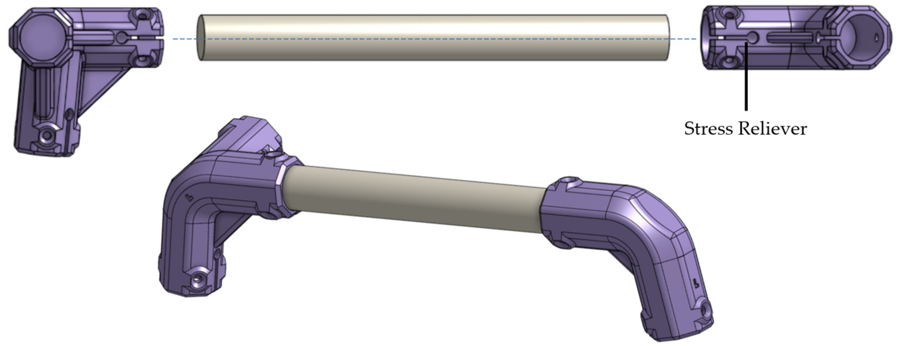
Appendix A. Open-Source Walker Labeled Diagram and Sample Calculations for Fit
The labeled diagram of the design for all the major components is shown in Figure A1.
Figure A1.
Labeled diagram of all wood dowel components.

Sample Calculations for Proper Fit
Height of walker: measured height of 860 mm from the user’s wrist to the ground.
Length of walker leg dowels to be cut:
Width of walker: desired overall width is 580 mm.
Length of top front dowel to be cut:
Depth of walker: desired length of handle is 150 mm.
Length of handlebar dowel to be cut:
Length of angled front dowel:
Length of top side and bottom side support dowels to be cut:
Appendix B. Calculations for User Weight Capacity
Appendix C. Assembly of Walker
Method for foot assembly:
- (1)
- Insert the Foot Washer flush into the Foot Body. It should fit snug.
- (2)
- Slide the Foot Cushion into the bottom of the Foot Body and exert a good amount of force to press it into the tight space. A helpful tip is to press with the palm which allows the full arm to exert force. See Figure A2.
Figure A2.
Assembling foot.

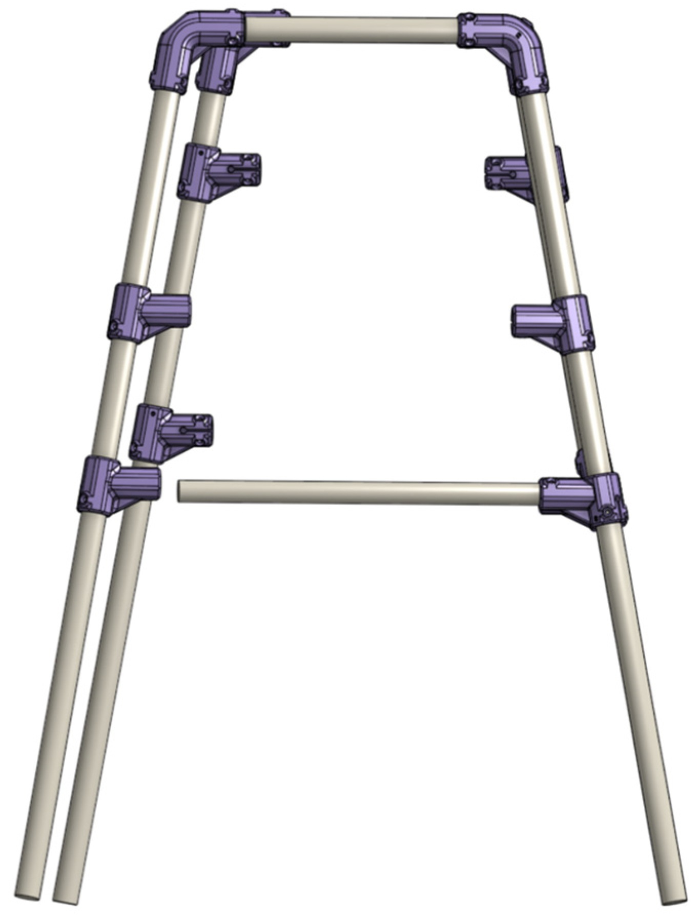
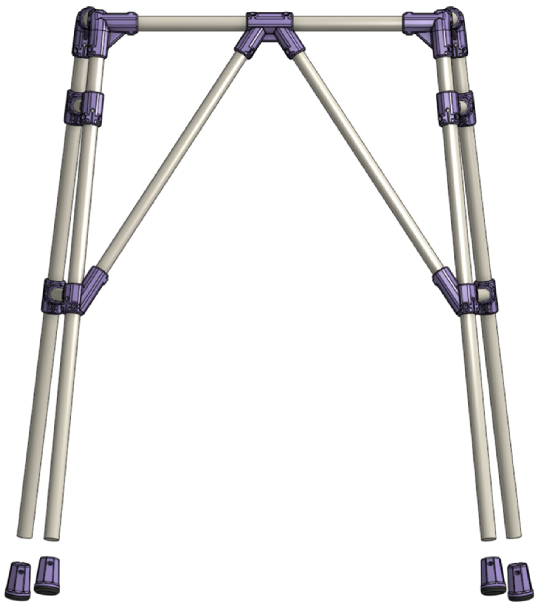
Method for walker assembly:
- (1)
- Measure and mark the center of the Top Front dowel. Then, mark half the length of the middle support part on either side of the first mark.
- (2)
- Align the middle support through the dowel with the marks and secure it using screws and a drill.
- (3)
- Measure and draw a center line along the length of the handlebar dowel (lateral area).
- (4)
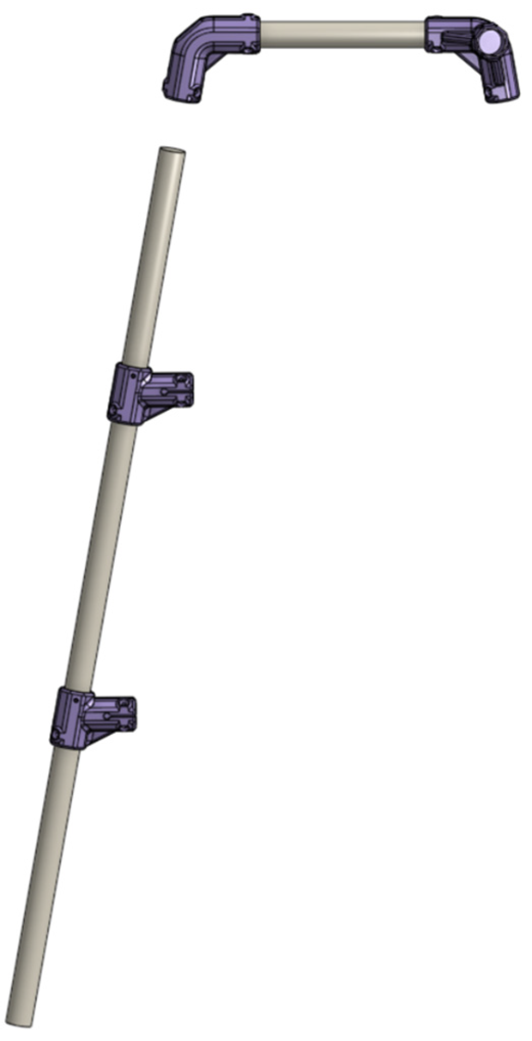
- Secure the Ang 2 Connector [L] into the side without the letter and Ang 3 Connector [L] onto either ends of the handlebar with both stress relievers (slit with a circle attached) centered to the line. See Figure A3 to ensure Ang 3 Connector is in the correct direction by refereeing to the orientation of the letter.
Figure A3.
Handle bar assembly.

- (5)
- Secure a leg dowel onto the Ang 2 Connector [L].
- (6)
- Slide two Ang Side Supports [O] onto the leg dowel with the stress relievers pointing to the right and the [O] symbol positioned at the top. See Figure A4.
Figure A4.
First half of leg assembly.

- (7)
- Secure a leg dowel onto the Ang 3 Connector [L] on the end with the stress relieves pointing in the same direction.
- (8)
- Slide one Ang Side Support [□] onto the leg dowel with the stress relievers pointing to the right and the [□] symbol positioned at the top. Following that by sliding the Ang Mid Support [L]. See Figure A5.
Figure A5.
Second half of leg assembly.

- (9)
- Repeat steps 3–8 for the right side and where you used the [O] part will now be [□].
- (10)
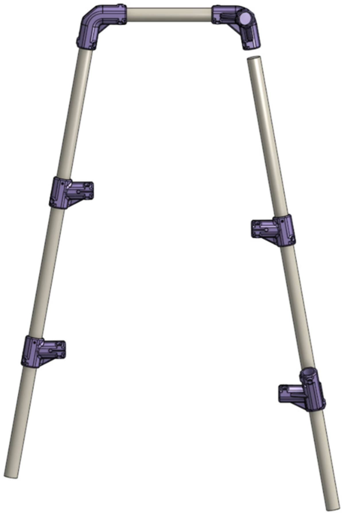
- Insert (do not secure) the last connection of Ang 3 Connectors onto either ends of the top front dowel. By this step, the overall frame of the walker is constructed. See Figure A6.
Figure A6.
Connected both left and right sides.

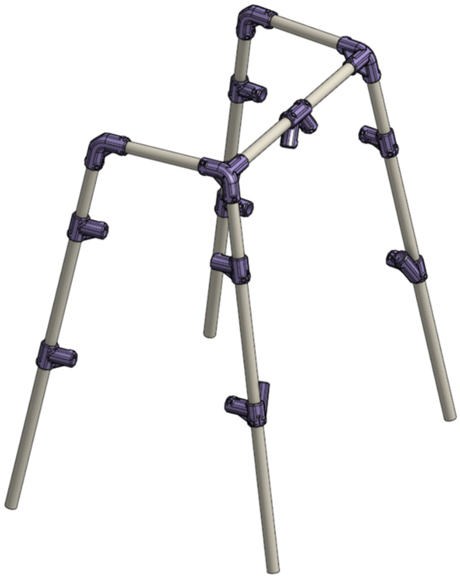
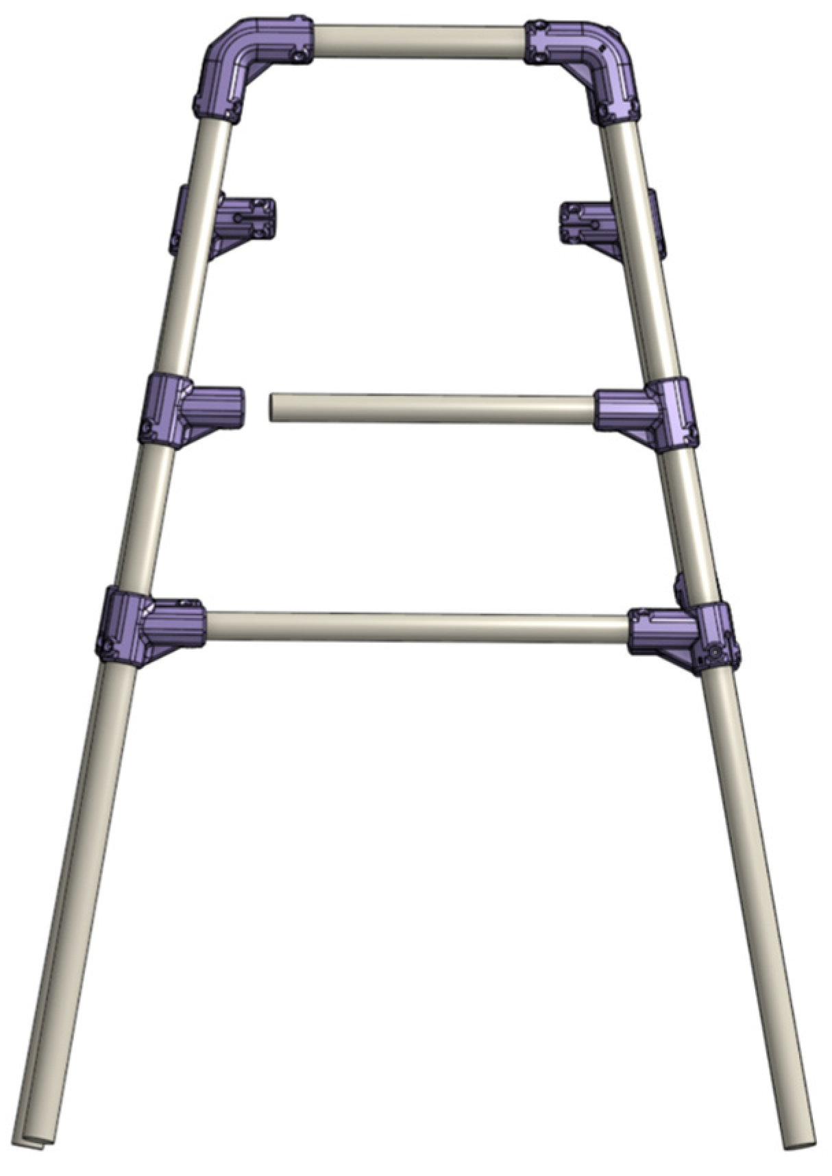
- (11)
- Secure both angled front dowels onto the middle support and lay the walker upside down on a flat surface so the top front dowel side is resting on the ground.
- (12)
- Slide one of the Ang Mid Support into the other end of the angled front dowel. Be cautious when carrying this out as the fit will be tight, and ensure the dowel sits fully into the connectors. Secure it once it is in place. See Figure A7.
Figure A7.
Connected first angled support.

- (13)
- Repeat step 12 for the remaining side.
- (14)
- Secure the Ang 3 Connectors onto the top front dowel.
- (15)
- Position the walker right side up. Secure the bottom side support dowel into the fixed Ang Mid Support part. Unsecure the Ang 2 Connector to add room and slowly move the corresponding Ang Side Support into the dowel. Be cautious as forcing it in place poses a risk of breaking the parts. Once fully in place, all the parts on that one side can be secured. See Figure A8.
Figure A8.
Connected bottom side connector.

- (16)
- Move the top Ang Side Connectors down from the top by 150 mm. Insert the top side support into one of the connectors. try to align both connectors in parallel and slowly move them towards the top of the walker so the top side dowel starts to fit into the other connector. Keep moving them incrementally until the dowel is fully in (see Figure A9).
Figure A9.
Connected top side connector.

- (17)
- Repeat steps 15–16 for the other side.
- (18)
- Secure all four feet onto ends of the leg dowels (Figure A10).
Figure A10.
Connecting feet.

Appendix D. Cost Calculations
The price of the wood dowels is summarized in Table A1, that of screws is summarized in Table A2, and of that of 3D-printed parts is summarized in Table A3, along with the weights of each part. The total cost of constructing one open-source walker equates to CAD 65.52–86.97 depending on the use of recyclable or commercial filament with the majority of costs originating from purchasing wood dowels at CAD 45.29, followed by the filament cost of CAD 0.05–36.63, and that of the screws of CAD 5.05. Table A4 shows the cost comparison of the open-source walker with materials sourced from United States versus Canada, in USD.

Table A1.
Wood dowel diameter size with its corresponding weight and price.
| Diameter Size | Quantity | Total Used Length (m) | Total Weight of Length (kg) | Total Cost (CAD$) |
|---|---|---|---|---|
| 19.19 * | 2 | 2.27 | 0.41 | 13.65 |
| 22.4 ** | 5 | 4.12 | 0.95 | 31.64 |
| Total | 6.39 | 1.36 | 45.28 |
* Dowels were purchased at CAD 6.49 + HST per 1.22 m with a net weight of 0.18 kg. ** Dowels were purchased at CAD 8.29 + HST per 1.22 m with a net weight of 0.23 kg.
Table A2.
Screw weight and price.
| Screws | Quantity | Weight (g) | Price (CAD) |
|---|---|---|---|
| M6 1/2 inch * | 82 | 65.6 | 5.05 |
* Weight of each screw was 0.80 g.
Table A3.
3D-printed parts weight, price, and time calculations using PETG and TPU 85A.
| PETG Parts * | Quantity | Weight/Part (g) | Total Weight (g) | Cost (CAD) | Time |
|---|---|---|---|---|---|
| Ang 3 Connector [L] | 1 | 77.22 | 77.22 | 1.87 | 1 h 37 min |
| Any 3 Connector [R] | 1 | 77.21 | 77.21 | 1.87 | 1 h 37 min |
| Ang 2 Connector [L] | 1 | 65.22 | 65.22 | 1.58 | 1 h 18 min |
| Ang 2 Connector [R] | 1 | 65.22 | 65.22 | 1.58 | 1 h 18 min |
| Ang Mid Support [L] | 1 | 78.91 | 78.91 | 1.91 | 1 h 45 min |
| Ang Mid Support [R] | 1 | 78.90 | 78.9 | 1.91 | 1 h 45 min |
| Middle Support | 1 | 73.33 | 73.33 | 1.77 | 1 h 32 min |
| Ang Side Support [O] | 3 | 45.24 | 135.72 | 3.28 | 2 h 48 min |
| Ang Side Support [□] | 3 | 45.33 | 135.99 | 3.29 | 2 h 51 min |
| Foot Body | 4 | 25.24 | 100.96 | 2.44 | 2 h 20 min |
| Total | 888.68 | 21.50 | 18 h 51min | ||
| TPU Parts ** | |||||
| Foot Cushion | 4 | 9.53 | 38.12 | 3.10 | 3 h 12 min |
| Foot Washer | 4 | 1.18 | 4.72 | 0.38 | 24 min |
| Handle Grip | 2 | 71.56 | 143.12 | 11.64 | 12 h 16 min |
| Total | 185.96 | 15.13 | 15 h 52 min | ||
| Total of All | 1074.64 | 36.63 | 34 h 43 min |
* Cost is calculated based on a 1 kg Polymaker PETG Filament spool priced at CAD 21.41 + HST. ** Cost is calculated based on a 0.5 kg NinjaFlex TPU 85A Filament spool priced at CAD 36.00 + HST.
Table A4.
Cost comparison of the open walker with materials sourced from United States versus Canada, in USD, along with a comparison of using commercial PETG versus Recyclebot PETG filament.
Table A4.
Cost comparison of the open walker with materials sourced from United States versus Canada, in USD, along with a comparison of using commercial PETG versus Recyclebot PETG filament.
| Material | United States (USD) | Canada (USD) | Canada (CAD) |
|---|---|---|---|
| Screws | 8.2 | 3.69 | 5.05 |
| 19.19 mm (3/4in) Wood Dowel | 12.96 | 9.96 | 13.65 |
| 22.4 mm (7/8in) Wood Dowel | 83.1 | 23.09 | 31.64 |
| Commercial PETG | 19.58 | 15.69 | 21.50 |
| Recycled PETG | 0.03 | 0.03 | 0.04 |
| Commercial TPU | 11.04 | 11.04 | 15.13 |
| Recycled TPU | 0.01 | 0.01 | 0.01 |
| Total Commercial PETG/TPU Cost | 134.88 | 63.47 | 86.97 |
| Total Recyclable PETG/TPU Cost | 115.34 | 36.78 | 65.52 |
* Cost of materials from Canada were taken from the above tables and converted to USD using a 1.37 CAD–USD exchange rate.
References
- Iezzoni, L. When Walking Fails: Mobility Problems of Adults with Chronic Conditions; University of California Press: Berkeley, CA, USA, 2003; ISBN 978-0-520-23819-0. [Google Scholar]
- CDC Disability Impacts All of Us Infographic|CDC. Available online: https://www.cdc.gov/ncbddd/disabilityandhealth/infographic-disability-impacts-all.html (accessed on 3 February 2023).
- Orgera, K.; Damico, A. How Many Seniors Are Living in Poverty? National and State Estimates under the Official and Supplemental Poverty Measures in 2016; The Henry J. Kaiser Family Foundation: Oakland, CA, USA, 2018. [Google Scholar]
- UN. World’s Poorest Nations Need International Support, Experts Tell Preparatory Committee, as E-Commerce, Global Market Access Take Centre Stage. Available online: https://press.un.org/en/2021/dev3440.doc.htm (accessed on 24 February 2023).
- Walkers—Google Shopping. Available online: https://www.google.ca/search?q=walkers&client=firefox-b-d&source=lnms&tbm=shop&sa=X&ved=2ahUKEwivzOW-t7D9AhUEmYkEHcLIC6cQ_AUoAXoECAEQAw (accessed on 24 February 2023).
- Iezzoni, L.I.; McCarthy, E.P.; Davis, R.B.; Siebens, H. Mobility difficulties are not only a problem of old age. J. Gen. Intern. Med. 2001, 16, 235–243. [Google Scholar] [CrossRef] [PubMed] [Green Version]
- U.S. Census Bureau. Poverty Rate of Children Higher Than National Rate, Lower for Older Populations. Available online: https://www.census.gov/library/stories/2022/10/poverty-rate-varies-by-age-groups.html (accessed on 3 February 2023).
- U.S. Census Bureau. The U.S. Joins Other Countries with Large Aging Populations. Available online: https://www.census.gov/library/stories/2018/03/graying-america.html (accessed on 3 February 2023).
- Gershenfeld, N. How to Make almost Anything: The Digital Fabrication Revolution. 2012. Available online: http://cba.mit.edu/docs/papers/12.09.FA.pdf (accessed on 28 October 2017).
- Markillie, P. A Third Industrial Revolution. The Economist. 2012. Available online: https://www.economist.com/leaders/2012/04/21/the-third-industrial-revolution (accessed on 11 October 2017).
- Rundle, G. A Revolution in the Making: 3D Printing, Robots and the Future; Affirm Press: South Melbourne, Australia, 2014; ISBN 978-1-922213-30-3. [Google Scholar]
- Gwamuri, J.; Wittbrodt, B.; Anzalone, N.; Pearce, J. Reversing the Trend of Large Scale and Centralization in Manufacturing: The Case of Distributed Manufacturing of Customizable 3-D-Printable Self-Adjustable Glasses. Chall. Sustain. 2014, 2, 30–40. [Google Scholar] [CrossRef]
- Anderson, P.; Sherman, C.A. A discussion of new business models for 3D printing. Int. J. Technol. Mark. 2007, 2, 280–294. [Google Scholar] [CrossRef]
- Laplume, A.; Anzalone, G.; Pearce, J. Open-source, self-replicating 3-D printer factory for small-business manufacturing. Int. J. Adv. Manuf. Technol. 2015, 85, 633–642. [Google Scholar] [CrossRef] [Green Version]
- Bogle, A. Can UPS Help Make 3-D Printing Mainstream? Available online: http://www.slate.com/blogs/future_tense/2013/08/02/ups_plans_to_test_3_d_printing_services_in_u_s_stores.html (accessed on 22 March 2018).
- Home Depot|Diy Meets Miy (Make IT Yourself). Available online: https://www.makerbot.com/media-center/2014/07/14/home-depot-diy-meets-miy-make (accessed on 22 March 2018).
- Seo-Zindy, R.; Heeks, R. Researching the Emergence of 3D Printing, Makerspaces, Hackerspaces and FabLabs in the Global South: A Scoping Review and Research Agenda on Digital Innovation and Fabrication Networks. Electron. J. Inf. Syst. Dev. Ctries. 2017, 80, 1–24. [Google Scholar] [CrossRef] [Green Version]
- Beltagui, A.; Sesis, A.; Stylos, N. A Bricolage Perspective on Democratising Innovation: The Case of 3D Printing in Makerspaces. Technol. Forecast. Soc. Chang. 2021, 163, 120453. [Google Scholar] [CrossRef]
- Kantaros, A.; Diegel, O.; Piromalis, D.; Tsaramirsis, G.; Khadidos, A.O.; Khadidos, A.O.; Khan, F.Q.; Jan, S. 3D Printing: Making an Innovative Technology Widely Accessible through Makerspaces and Outsourced Services. Mater. Today Proc. 2022, 49, 2712–2723. [Google Scholar] [CrossRef]
- Byard, D.J.; Woer, A.L.; Oakley, R.B.; Fiedler, M.J.; Snabes, S.L.; Pearce, J.M. Green Fab Lab Applications of Large-Area Waste Polymer-Based Additive Manufacturing. Addit. Manuf. 2019, 27, 515–525. [Google Scholar] [CrossRef] [Green Version]
- Moorefield-Lang, H. Makers in the library: Case studies of 3D printers and maker spaces in library settings. Libr. Hi Tech 2014, 32, 583–593. [Google Scholar] [CrossRef]
- Moorefield-Lang, H. Change in the Making: Makerspaces and the Ever-Changing Landscape of Libraries. TechTrends 2015, 59, 107–112. [Google Scholar] [CrossRef]
- Pryor, S. Implementing a 3D Printing Service in an Academic Library. J. Libr. Adm. 2014, 54, 1–10. [Google Scholar] [CrossRef] [Green Version]
- Dupont, L.; Kasmi, F.; Pearce, J.M.; Ortt, R.J. “Do-It-Together” and Innovation: Transforming European Industry. J. Innov. Econ. Manag. 2023, 40, 1–11. [Google Scholar] [CrossRef]
- Marche, B.; Kasmi, F.; Mayer, F.; Dupont, L. Implementing Do-It-Together: The Cross-Fertilization of Do-It-Yourself and Open Manufacturing. J. Innov. Econ. Manag. 2023, 40, 13–38. [Google Scholar] [CrossRef]
- Hassan, M.; Mies, R.; Jochem, R. Key Enablers towards Mature Company-Community Collaboration in Open Source Hardware. J. Innov. Econ. Manag. 2023, 40, 159–191. [Google Scholar] [CrossRef]
- Laplume, A.; Petersen, B.; Pearce, J. Global value chains from a 3D printing perspective. J. Int. Bus. Stud. 2016, 47, 595–609. [Google Scholar] [CrossRef]
- Weber, S. The Success of Open Source; Harvard University Press: Cambridge, MA, USA, 2004; ISBN 978-0-674-01292-9. [Google Scholar]
- Gibb, A.; Abadie, S. Building Open Source Hardware: DIY Manufacturing for Hackers and Makers, 1st ed.; Addison-Wesley Professional: Boston, MA, USA, 2014; ISBN 978-0-321-90604-5. [Google Scholar]
- Oberloier, S.; Pearce, J.; Oberloier, S.; Pearce, J.M. General Design Procedure for Free and Open-Source Hardware for Scientific Equipment. Designs 2017, 2, 2. [Google Scholar] [CrossRef] [Green Version]
- Pearce, J.M. Sponsored Libre Research Agreements to Create Free and Open Source Software and Hardware. Inventions 2018, 3, 44. [Google Scholar] [CrossRef] [Green Version]
- Rundle, G. A Revolution in the Making; Simon and Schuster: New York, NY, USA, 2014. [Google Scholar]
- Sells, E.; Bailard, S.; Smith, Z.; Bowyer, A.; Olliver, V. RepRap: The Replicating Rapid Prototyper-Maximizing Customizability by Breeding the Means of Production 2010. In Proceedings of the World Conference on Mass Customization and Personalization, Cambridge, MA, USA, 7–10 October 2007; ISBN 978-981-4280-25-9. [Google Scholar]
- Jones, R.; Haufe, P.; Sells, E.; Iravani, P.; Olliver, V.; Palmer, C.; Bowyer, A. RepRap-the Replicating Rapid Prototyper. Robotica 2011, 29, 177–191. [Google Scholar] [CrossRef] [Green Version]
- Bowyer, A. 3D Printing and Humanity’s First Imperfect Replicator. 3D Print. Addit. Manuf. 2014, 1, 4–5. [Google Scholar] [CrossRef]
- Wittbrodt, B.; Glover, A.; Laureto, J.; Anzalone, G.; Oppliger, D.; Irwin, J.; Pearce, J. Life-Cycle Economic Analysis of Distributed Manufacturing with Open-Source 3-D Printers. Mechatronics 2013, 23, 713–726. [Google Scholar] [CrossRef] [Green Version]
- Petersen, E.E.; Pearce, J. Emergence of Home Manufacturing in the Developed World: Return on Investment for Open-Source 3-D Printers. Technologies 2017, 5, 7. [Google Scholar] [CrossRef] [Green Version]
- Petersen, E.E.; Kidd, R.W.; Pearce, J.M. Impact of DIY Home Manufacturing with 3D Printing on the Toy and Game Market. Technologies 2017, 5, 45. [Google Scholar] [CrossRef] [Green Version]
- Pearce, J.; Qian, J.-Y. Economic Impact of DIY Home Manufacturing of Consumer Products from Free and Open Source Designs. Eur. J. Soc. Impact Circ. Econ. 2022, 3, 9906. [Google Scholar] [CrossRef]
- Gallup, N.; Bow, J.K.; Pearce, J.M. Economic Potential for Distributed Manufacturing of Adaptive Aids for Arthritis Patients in the U.S. Geriatrics 2018, 3, 89. [Google Scholar] [CrossRef] [PubMed] [Green Version]
- Makers Making Change. Available online: https://makersmakingchange.com/ (accessed on 20 February 2023).
- Smith, P. Commons People: Additive Manufacturing Enabled Collaborative Commons Production. In Proceedings of the 15th RDPM Conference, Loughborough, UK, 27–28 April 2015. [Google Scholar]
- Ariza, J.Á.; Pearce, J.M. Low-Cost Assistive Technologies for Disabled People Using Open-Source Hardware and Software: A Systematic Literature Review. IEEE Access 2022, 10, 124894–124927. [Google Scholar] [CrossRef]
- Bradley, S.M.; Hernandez, C.R. Geriatric Assistive Devices. AAFP. 2011. Available online: https://www.aafp.org/pubs/afp/issues/2011/0815/p405.html (accessed on 31 January 2023).
- So, A. Open Source Static Walker Assembly. 2023. Available online: https://cad.onshape.com/documents/f76431cccbb43ef79b0eb32f/w/2534bbc3536ada6a0d339e1a/e/2bbe74a159750ce6bb874837?renderMode=0&uiState=6424734000dc3b67df226d38 (accessed on 30 March 2023).
- Open Source Walker Source Files. 2023. Available online: https://osf.io/v3njw/ (accessed on 30 March 2023).
- Sinha, A.; Kutnar, A. Carbon Footprint versus Performance of Aluminum, Plastic, and Wood Window Frames from Cradle to Gate. Buildings 2012, 2, 542–553. [Google Scholar] [CrossRef] [Green Version]
- Hardwood vs. Softwood—Difference and Comparison|Diffen. Available online: https://www.diffen.com/difference/Hardwood_vs_Softwood (accessed on 13 January 2023).
- PolyLite PETG. Polymaker. Available online: https://us.polymaker.com/products/polylite-petg?variant=39574344761401 (accessed on 17 March 2023).
- NinjaFlex 3D Printer Filament (85A). NinjaTek. Available online: https://ninjatek.com/shop/ninjaflex/ (accessed on 5 January 2023).
- Using a Walker Correctly—Tricks of the Trade. OTflourish. Available online: https://seniorsflourish.com/walker/ (accessed on 6 January 2023).
- ISO 11199-1:2021(en); Assistive Products for Walking Manipulated by Both Arms—Requirements and Test Methods—Part 1: Walking Frames. ISO, 2021. Available online: https://www.iso.org/obp/ui/#iso:std:iso:11199:-1:ed-2:v1:en (accessed on 22 December 2022).
- NIH. ImageJ. Available online: https://imagej.nih.gov/ij/download.html (accessed on 5 January 2023).
- Statistics Canada, Table 1 Mean Height, Weight, Body Mass Index (BMI) and Prevalence of Obesity, by Collection Method and Sex, Household Population Aged 18 to 79, Canada, 2008, 2007 to 2009, and 2005. 2023. Available online: https://www150.statcan.gc.ca/n1/pub/82-003-x/2011003/article/11533/tbl/tbl1-eng.htm (accessed on 31 January 2023).
- How Much Does a Walker Weigh? WalkerForSeniors. 2019. Available online: https://walkerforseniors.com/how-much-does-a-walker-weigh/ (accessed on 24 February 2023).
- Rohwerder, B. Assistive Technologies in Developing Countries; K4D Helpdesk Report; Institute of Development Studies: Brighton, UK, 2018. Available online: https://assets.publishing.service.gov.uk/media/5af976ab40f0b622d4e9810f/Assistive_technologies_in_developing-countries.pdf (accessed on 2 June 2023).
- UNICEF. Global Report on Assistive Technology; World Health Organization: Geneva, Switzerland, 2022; ISBN 9789240049451. [Google Scholar]
- Tanikella, N.G.; Wittbrodt, B.; Pearce, J.M. Tensile Strength of Commercial Polymer Materials for Fused Filament Fabrication 3D Printing. Addit. Manuf. 2017, 15, 40–47. [Google Scholar] [CrossRef] [Green Version]
- Petsiuk, A.L.; Pearce, J.M. Open Source Computer Vision-Based Layer-Wise 3D Printing Analysis. Addit. Manuf. 2020, 36, 101473. [Google Scholar] [CrossRef]
- Petsiuk, A.; Pearce, J.M. Towards Smart Monitored AM: Open Source In-Situ Layer-Wise 3D Printing Image Anomaly Detection Using Histograms of Oriented Gradients and a Physics-Based Rendering Engine. Addit. Manuf. 2022, 52, 102690. [Google Scholar] [CrossRef]
- Petsiuk, A.; Singh, H.; Dadhwal, H.; Pearce, J.M. Synthetic-To-Real Composite Semantic Segmentation in Additive Manufacturing. arXiv 2022, arXiv:2210.07466. [Google Scholar]
- Tymrak, B.M.; Kreiger, M.; Pearce, J.M. Mechanical Properties of Components Fabricated with Open-Source 3-D Printers under Realistic Environmental Conditions. Mater. Des. 2014, 58, 242–246. [Google Scholar] [CrossRef] [Green Version]
- Dolzyk, G.; Jung, S. Tensile and Fatigue Analysis of 3D-Printed Polyethylene Terephthalate Glycol. J. Fail. Anal. Prev. 2019, 19, 511–518. [Google Scholar] [CrossRef]
- Vidakis, N.; Petousis, M.; Velidakis, E.; Liebscher, M.; Mechtcherine, V.; Tzounis, L. On the Strain Rate Sensitivity of Fused Filament Fabrication (FFF) Processed PLA, ABS, PETG, PA6, and PP Thermoplastic Polymers. Polymers 2020, 12, 2924. [Google Scholar] [CrossRef] [PubMed]
- Özen, A.; Abali, B.E.; Völlmecke, C.; Gerstel, J.; Auhl, D. Exploring the Role of Manufacturing Parameters on Microstructure and Mechanical Properties in Fused Deposition Modeling (FDM) Using PETG. Appl. Compos. Mater. 2021, 28, 1799–1828. [Google Scholar] [CrossRef]
- Sathish Kumar, K.; Soundararajan, R.; Shanthosh, G.; Saravanakumar, P.; Ratteesh, M. Augmenting Effect of Infill Density and Annealing on Mechanical Properties of PETG and CFPETG Composites Fabricated by FDM. Mater. Today Proc. 2021, 45, 2186–2191. [Google Scholar] [CrossRef]
- Ajay Kumar, M.; Khan, M.S.; Mishra, S.B. Effect of Machine Parameters on Strength and Hardness of FDM Printed Carbon Fiber Reinforced PETG Thermoplastics. Mater. Today Proc. 2020, 27, 975–983. [Google Scholar] [CrossRef]
- Khan, S.A.; Siddiqui, B.A.; Fahad, M.; Khan, M.A. Evaluation of the Effect of Infill Pattern on Mechanical Stregnth of Additively Manufactured Specimen. Mater. Sci. Forum 2017, 887, 128–132. [Google Scholar] [CrossRef]
- Cabreira, V.; Santana, R.M.C. Effect of Infill Pattern in Fused Filament Fabrication (FFF) 3D Printing on Materials Performance. Matéria 2020, 25. [Google Scholar] [CrossRef]
- Gonabadi, H.; Yadav, A.; Bull, S.J. The Effect of Processing Parameters on the Mechanical Characteristics of PLA Produced by a 3D FFF Printer. Int. J. Adv. Manuf. Technol. 2020, 111, 695–709. [Google Scholar] [CrossRef]
- Mahmood, S.; Qureshi, A.J.; Goh, K.L.; Talamona, D. Tensile Strength of Partially Filled FFF Printed Parts: Experimental Results. Rapid Prototyp. J. 2017, 23, 122–128. [Google Scholar] [CrossRef]
- Wittbrodt, B.; Pearce, J.M. The Effects of PLA Color on Material Properties of 3-D Printed Components. Addit. Manuf. 2015, 8, 110–116. [Google Scholar] [CrossRef] [Green Version]
- Mundt, M.; Batista, J.P.; Markert, B.; Bollheimer, C.; Laurentius, T. Walking with rollator: A systematic review of gait parameters in older persons. Eur. Rev. Aging Phys. Act. 2019, 16, 15. [Google Scholar] [CrossRef] [PubMed]
- Günther, D.; Heymel, B.; Günther, J.F.; Ederer, I. Continuous 3D-printing for additive manufacturing. Rapid Prototyp. J. 2014, 20, 320–327. [Google Scholar] [CrossRef]
- Woern, A.L.; McCaslin, J.R.; Pringle, A.M.; Pearce, J.M. RepRapable Recyclebot: Open source 3-D printable extruder for converting plastic to 3-D printing filament. HardwareX 2018, 4, e00026. [Google Scholar] [CrossRef]
- Product Certification & Standards Development. CSA Group. Available online: https://www.csagroup.org/store/?gclid=CjwKCAjwoIqhBhAGEiwArXT7Kzn7ftLLArIjf-4-_T2ypxREe2oLdvq-TcpYYxc5j-4Z1BFDSRlcOxoC9tAQAvD_BwE (accessed on 23 February 2023).
- Drugs and Health Products. Health Canada, 2022. Available online: https://www.canada.ca/en/health-canada/services/drugs-health-products.html (accessed on 23 February 2023).
- Overview of Device Regulation|FDA. 2020. Available online: https://www.fda.gov/medical-devices/device-advice-comprehensive-regulatory-assistance/overview-device-regulation#reg (accessed on 22 March 2023).
- Bachar, R.K.; Bhuniya, S.; Ghosh, S.K.; Sarkar, B. Controllable Energy Consumption in a Sustainable Smart Manufacturing Model Considering Superior Service, Flexible Demand, and Partial Outsourcing. Mathematics 2022, 10, 4517. [Google Scholar] [CrossRef]
- Wang, D.; Zhang, T.; Guo, X.; Ling, D.; Hu, L.; Jiang, G. The Potential of 3D Printing in Facilitating Carbon Neutrality. J. Environ. Sci. 2023, 130, 85–91. [Google Scholar] [CrossRef]
- Kreiger, M.; Pearce, J.M. Environmental Life Cycle Analysis of Distributed Three-Dimensional Printing and Conventional Manufacturing of Polymer Products. ACS Sustain. Chem. Eng. 2013, 1, 1511–1519. [Google Scholar] [CrossRef]
- Kreiger, M.; Pearce, J.M. Environmental Impacts of Distributed Manufacturing from 3-D Printing of Polymer Components and Products. MRS Online Proc. Libr. 2013, 1492, 85–90. [Google Scholar] [CrossRef] [Green Version]
- Agrawal, R.; Vinodh, S. State of Art Review on Sustainable Additive Manufacturing. Rapid Prototyp. J. 2019, 25, 1045–1060. [Google Scholar] [CrossRef]
- Hota, S.K.; Ghosh, S.K.; Sarkar, B. A Solution to the Transportation Hazard Problem in a Supply Chain with an Unreliable Manufacturer. AIMS Environ. Sci. 2022, 9, 354–380. [Google Scholar] [CrossRef]
Figure 1.
Dimensional measurements of tested walker design.

Figure 2.
Orientation of the 3D-printed parts on the print bed.

Figure 3.
3D-printed parts (orange) with support locations (light green) and brim (dark green).

Figure 4.
Printing orientation of handle, foot cushion and washer.

Figure 5.
Testing distributed load that replicates the span of a fists on the walker.

Figure 6.
Horizontal testing set up with the hydraulic hand pump in yellow, hydraulic cylinder in green, load cell in blue, and the displacement sensor clamped onto a fixed structure on the right.
Figure 6.
Horizontal testing set up with the hydraulic hand pump in yellow, hydraulic cylinder in green, load cell in blue, and the displacement sensor clamped onto a fixed structure on the right.

Figure 7.
(a) Angle analysis to determine the loading angle of a user while operating a walker onto the handlebar measured from the elbow to wrist using ImageJ. (b) Free body diagram of forces from the applied testing forces, from body weight, and from user.
Figure 7.
(a) Angle analysis to determine the loading angle of a user while operating a walker onto the handlebar measured from the elbow to wrist using ImageJ. (b) Free body diagram of forces from the applied testing forces, from body weight, and from user.

Figure 8.
Force–displacement curves for walker vertical testing results of five independent trials along with lines of best fit slope (the flat region used for the best fit slope was from a displacement of 5 mm until failure).
Figure 8.
Force–displacement curves for walker vertical testing results of five independent trials along with lines of best fit slope (the flat region used for the best fit slope was from a displacement of 5 mm until failure).

Figure 9.
Sample images of the failure occurring on handlebars after vertical walker testing.

Figure 10.
A Force–displacement curve for walker horizontal testing results of five trials along with lines of best fit slope (the flat region used for the best fit slope was from a displacement of 7 mm until failure).
Figure 10.
A Force–displacement curve for walker horizontal testing results of five trials along with lines of best fit slope (the flat region used for the best fit slope was from a displacement of 7 mm until failure).

Figure 11.
Sample images of failure occurring at the 3D-printed Ang 3 Connector part after horizontal walker testing.
Figure 11.
Sample images of failure occurring at the 3D-printed Ang 3 Connector part after horizontal walker testing.

Table 1.
List of names and quantity of 3D-printed parts.
| Name | Number of Parts |
|---|---|
| Ang 3 Connector [L] | 1 |
| Any 3 Connector [R] | 1 |
| Ang 2 Connector [L] | 1 |
| Ang 2 Connector [R] | 1 |
| Ang Mid Support [L] | 1 |
| Ang Mid Support [R] | 1 |
| Middle Support | 1 |
| Ang Side Support [O] | 3 |
| Ang Side Support [□] | 3 |
| Foot Body | 4 |
| Foot Cushion | 4 |
| Foot Washer | 4 |
| Handle Grip | 2 |
Table 2.
Slicing parameters for PETG and TPU 85A filaments.
| Slicing Parameter | PETG Value | TPU 85A Value |
|---|---|---|
| Layer Height | 0.6 mm | 0.15 |
| Wall Count | 6 | 2 |
| Infill Density | 80% | 30% (foot parts) |
| 15% (handle) | ||
| Infill Pattern | Gyroid | Gyroid |
| Printing Temperature | 225 °C | 238 °C |
| Bed Temperature | 85 °C | 50 °C |
Table 3.
Wood dowel part names and quantity.
| Name | Number of Parts |
|---|---|
| Top Front | 1 |
| Handlebar | 2 |
| Leg | 4 |
| Angled Front | 2 |
| Top Side Support | 2 |
| Bottom Side Support | 2 |
Disclaimer/Publisher’s Note: The statements, opinions and data contained in all publications are solely those of the individual author(s) and contributor(s) and not of MDPI and/or the editor(s). MDPI and/or the editor(s) disclaim responsibility for any injury to people or property resulting from any ideas, methods, instructions or products referred to in the content. |
© 2023 by the authors. Licensee MDPI, Basel, Switzerland. This article is an open access article distributed under the terms and conditions of the Creative Commons Attribution (CC BY) license (https://creativecommons.org/licenses/by/4.0/).
Share and Cite
MDPI and ACS Style
So, A.; Reeves, J.M.; Pearce, J.M. Open-Source Designs for Distributed Manufacturing of Low-Cost Customized Walkers. Inventions 2023, 8, 79. https://doi.org/10.3390/inventions8030079
AMA Style
So A, Reeves JM, Pearce JM. Open-Source Designs for Distributed Manufacturing of Low-Cost Customized Walkers. Inventions. 2023; 8(3):79. https://doi.org/10.3390/inventions8030079
Chicago/Turabian StyleSo, Anita, Jacob M. Reeves, and Joshua M. Pearce. 2023. "Open-Source Designs for Distributed Manufacturing of Low-Cost Customized Walkers" Inventions 8, no. 3: 79. https://doi.org/10.3390/inventions8030079