

Mini-Kilns for Charcoal-Making: An Eco-Friendly Solution for Small-Scale Production of Charcoal and Wood Vinegar
 ,
,  ,
,
Abstract
:1. Introduction
2. Materials and Methods
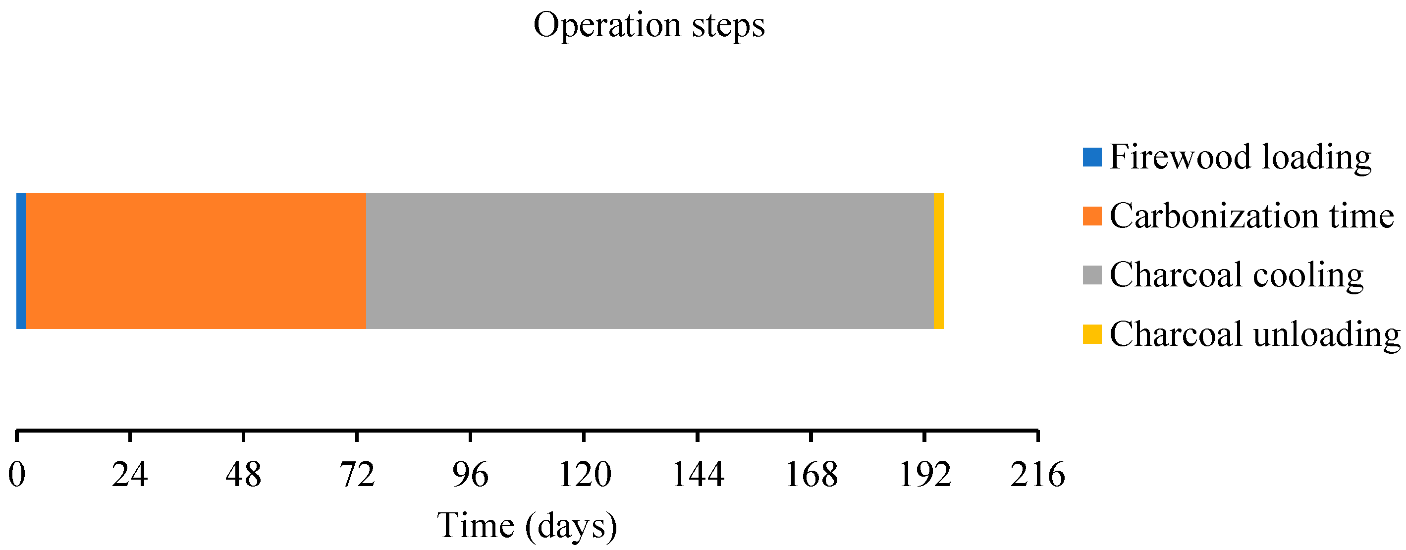
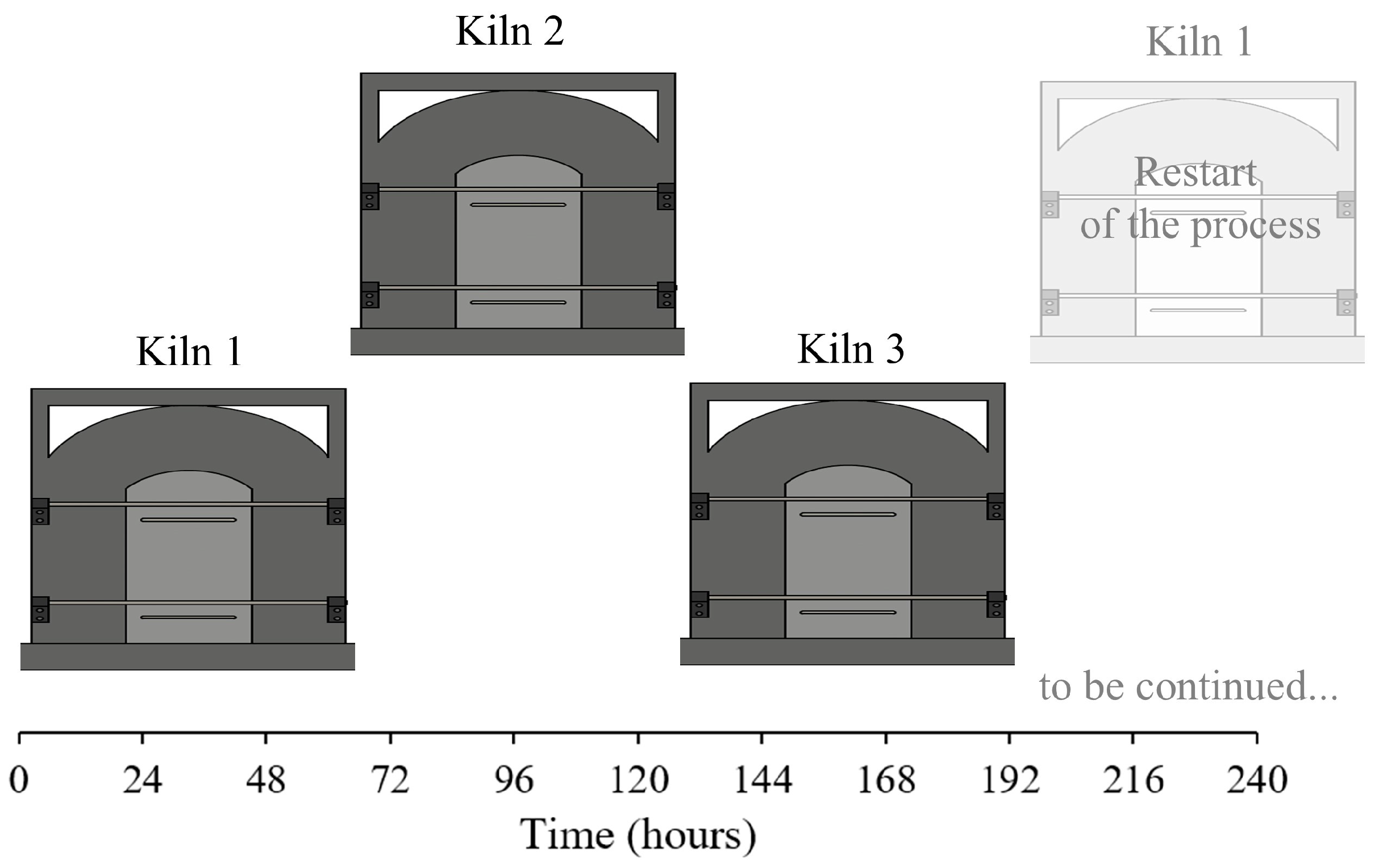
2.1. Project Premises
- ✓
- Firewood loading: 2 h;
- ✓
- Carbonization time: 72 h (3 days);
- ✓
- Charcoal cooling: 120 h (5 days);
- ✓
- Charcoal unloading: 2 h;
- ✓
- Total: 196 h.
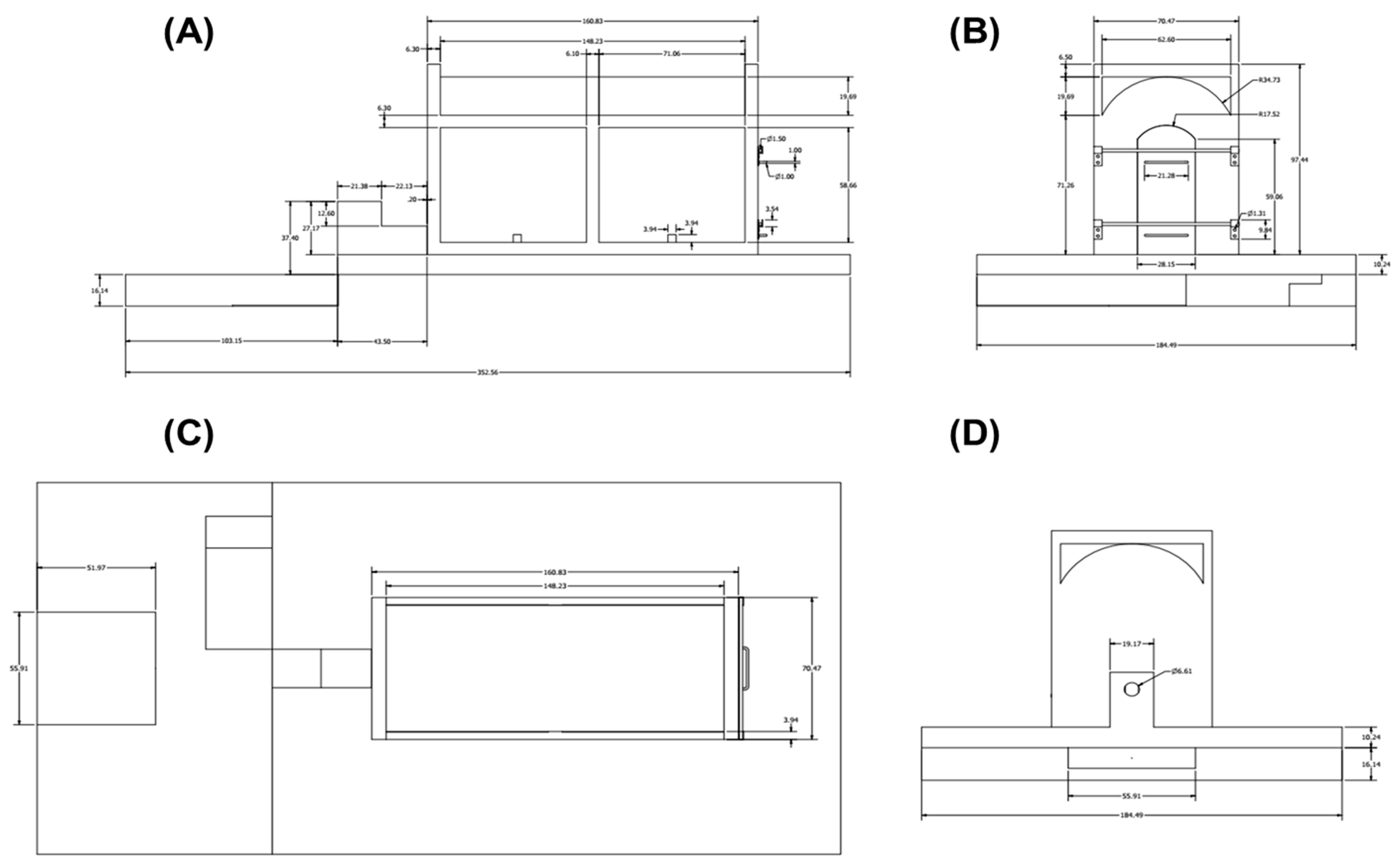
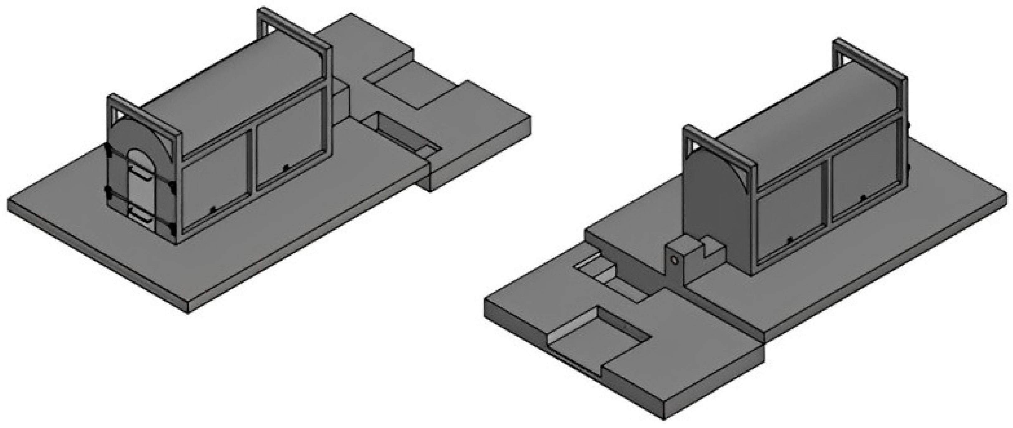
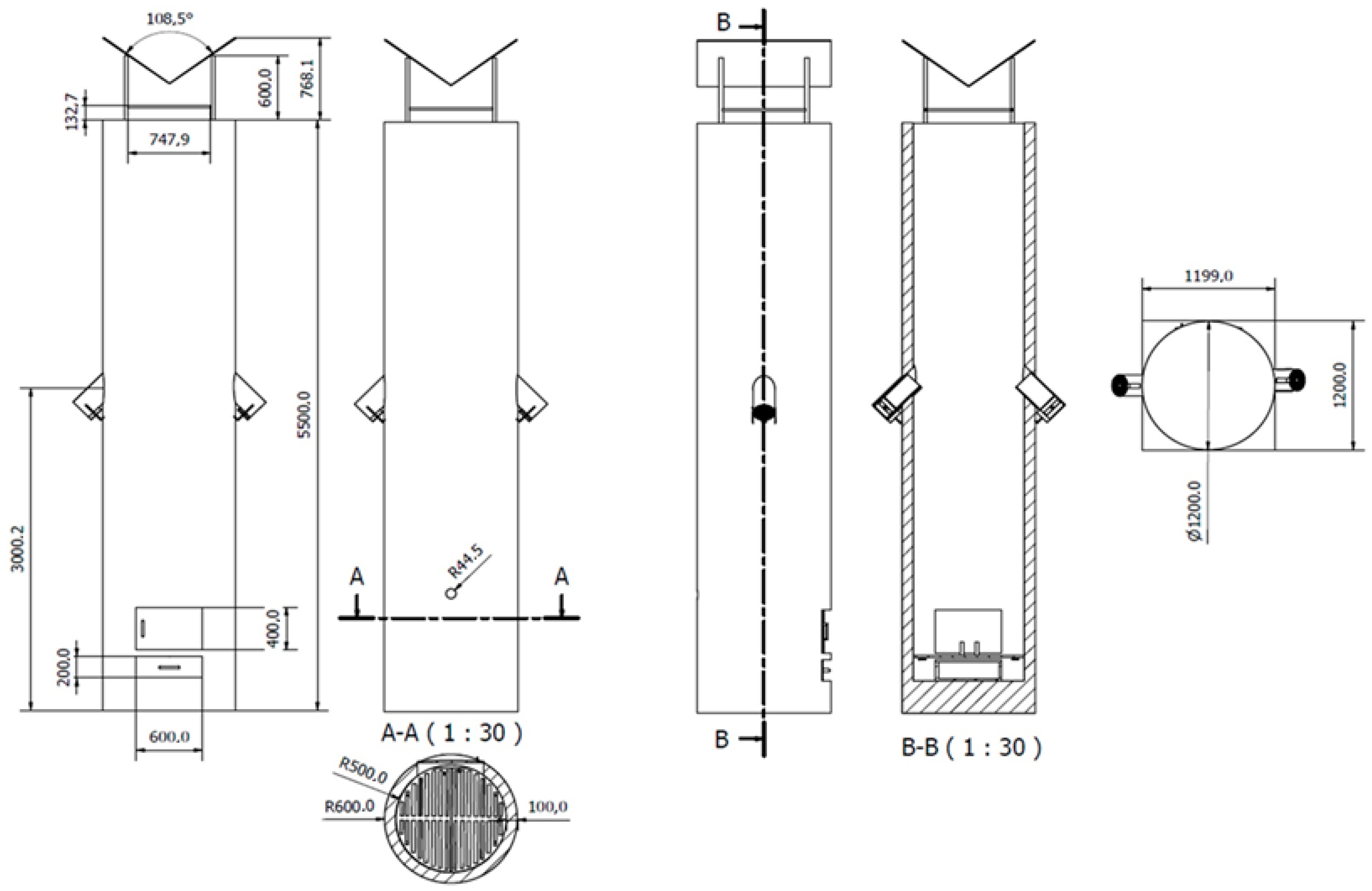
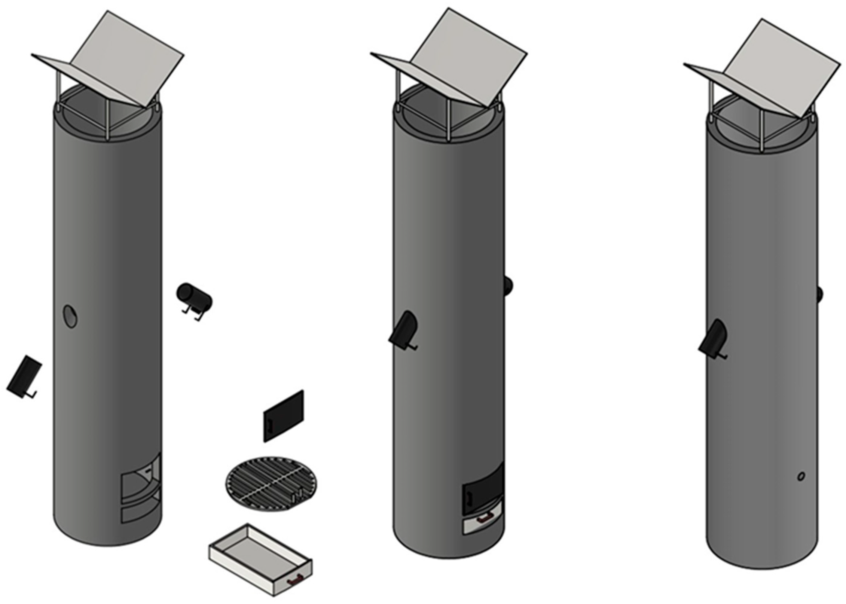
2.2. Carbonization Kilns
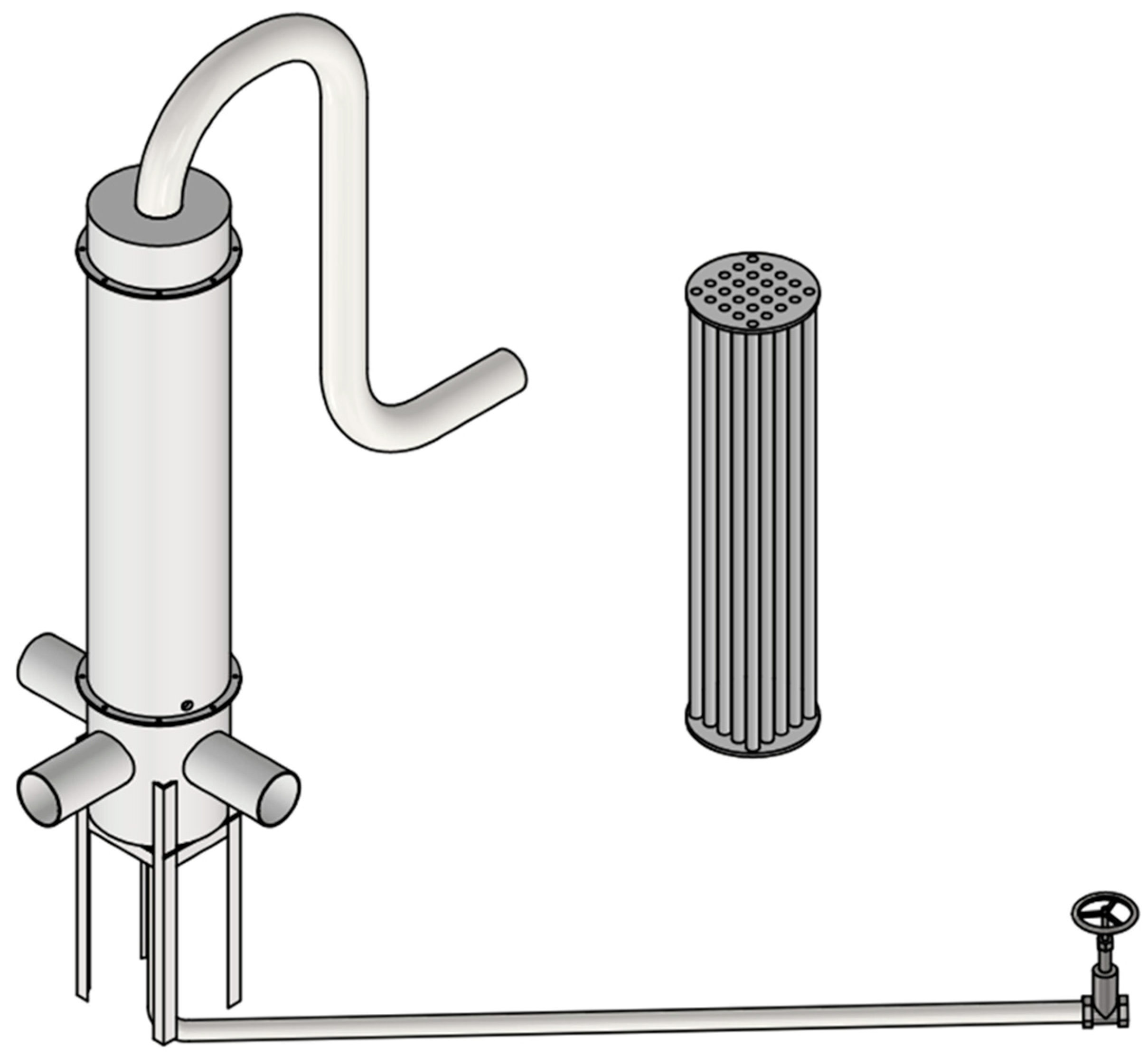
2.3. Condensing System for WV Recovery
2.3.1. Condensing System Design
2.3.2. Thermal Design of the Condensing System
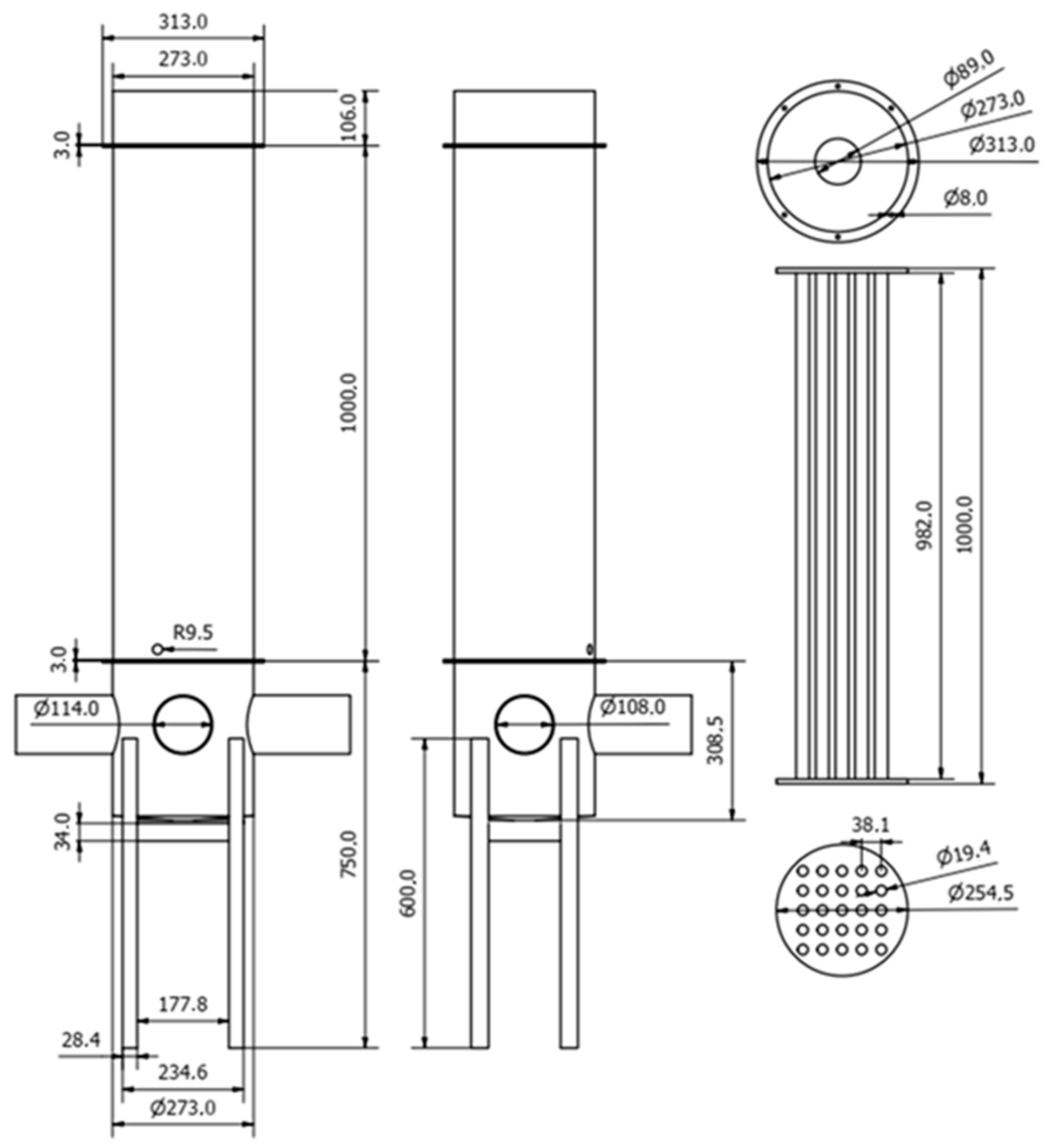
2.3.3. Mechanical Design of the Condensing System
Hull Sizing
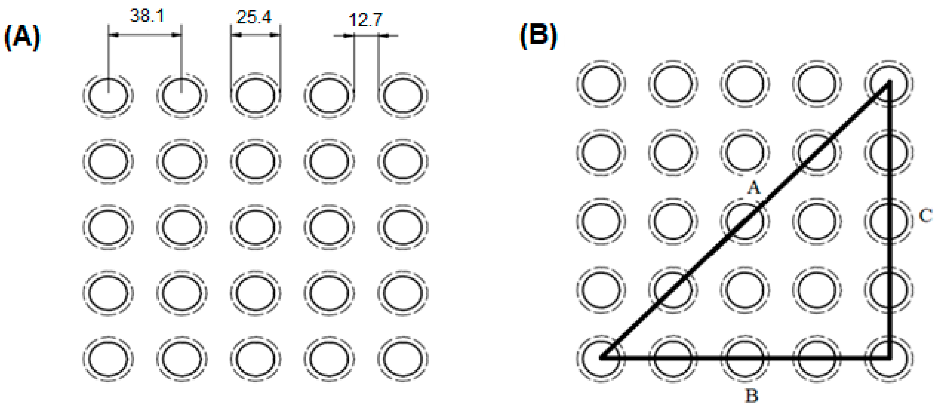
Tube Set Sizing
Maximum Allowable Working Pressure (MAWP)
Mirrors Sizing
Caps Sizing
Hydrostatic Pressure Test (PTH)
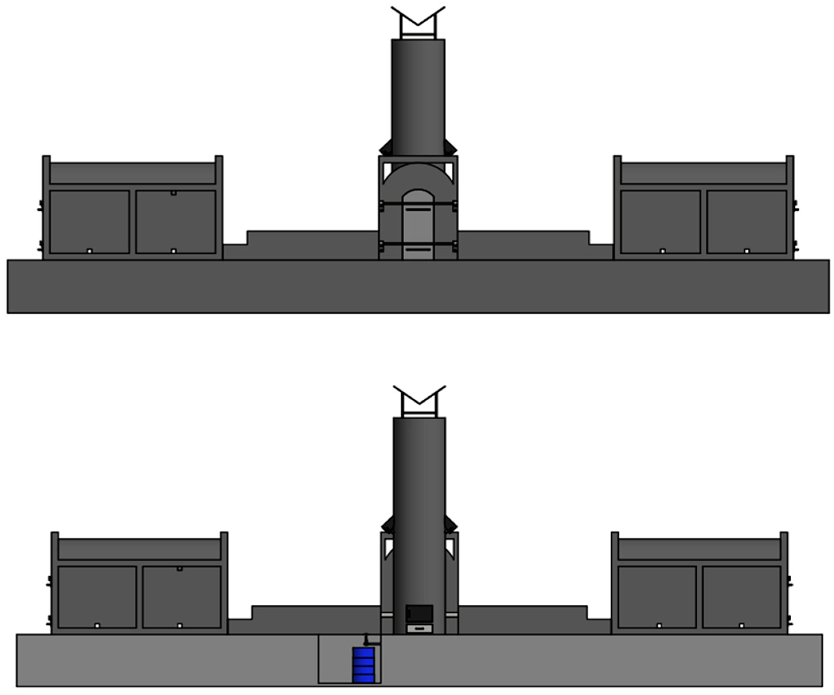
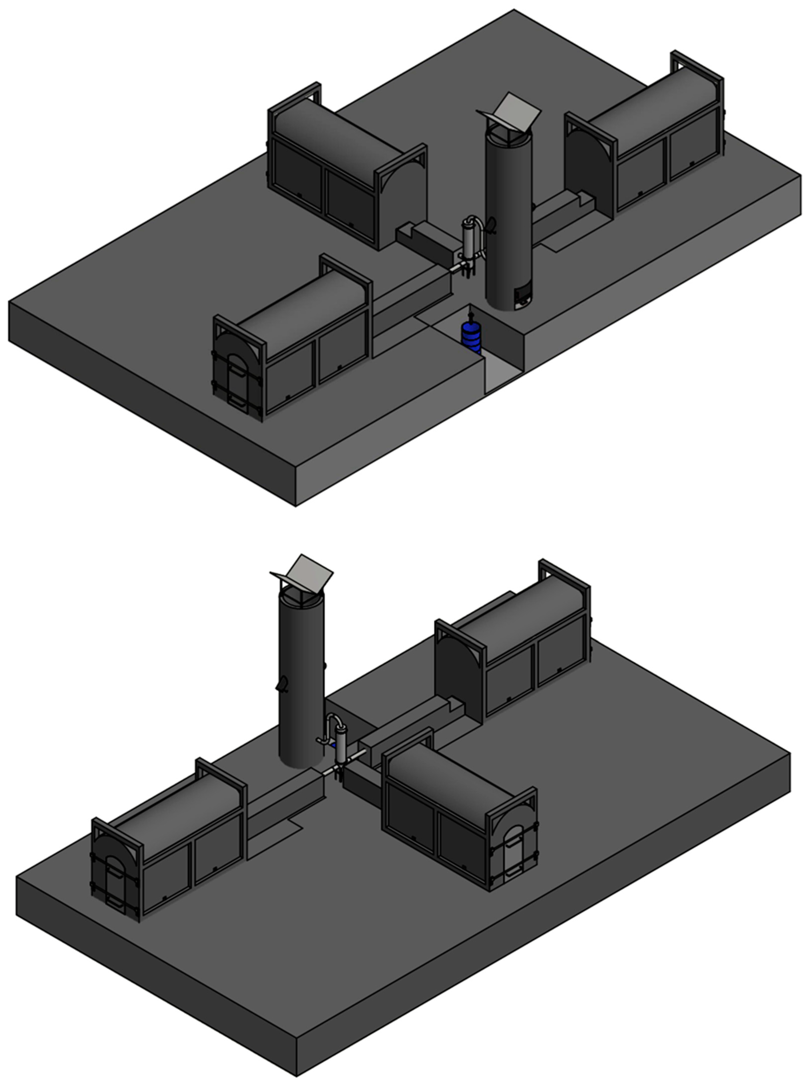
2.4. Smoke Burner
Smoke Burner Sizing
Average Specific Mass of Smoke Gases
Mass Flow Rate of Smoke Gases
Amount of Heat Required to Burn Smoke Gases
Rate of Fuel to Be Consumed by the Smoke Burner
Combustion Chamber Volume
Grate Surface Area
Fans
3. Results
4. Discussion
5. Conclusions
Author Contributions
Funding
Data Availability Statement
Acknowledgments
Conflicts of Interest
References
- Rodrigues, T. Model for the Conceptual Projects Development of Carbonization Kiln. Ph.D. Thesis, Universidade Tecnológica Federal do Paraná, Ponta Grossa, Brazil, 2019. [Google Scholar]
- Zola, F.C.; Colmenero, J.C.; Aragão, F.V.; Rodrigues, T.; Braghini, A., Jr. Multicriterial model for selecting a charcoal kiln. Energy 2020, 190, e116377. [Google Scholar] [CrossRef]
- IBÁ—Indústria Brasileira de Árvores. Relatório Anual Estatístico de 2021: Ano Base 2020. 2022. Available online: https://www.iba.org/publicacoes/relatorios (accessed on 20 January 2023).
- Pereira, E.G.; Fauller, H.; Magalhães, M.; Guirardi, B.; Martins, M.A. Potential use of wood pyrolysis coproducts: A review. Environ. Prog. Sustain. Energy 2022, 41, e13705. [Google Scholar] [CrossRef]
- Paradela, F.M.R. Study of the Pyrolysis of Mixtures of Plastic Waste, Tires and Biomass. Ph.D. Thesis, Universidade Nova de Lisboa, Lisboa, Portugal, 2012. [Google Scholar]
- Farias, S.P.; Almeida, A.V.D.L.; Nascimento, E.S.; SolettI, J.I.; Balliano, T.L.; Moura Filho, G.; Muniz, M.F.S. In vitro and in vivo control of yam dry rot nematodes using pyroligneous extracts from palm trees. Rev. Ceres 2020, 67, 482–490. [Google Scholar] [CrossRef]
- Biscaia, R.V.B. Methodology for the Development of a Transportable Carbonization Kiln Project. Ph.D. Thesis, Universidade de São Paulo, Sao Paulo, Brazil, 2021. [Google Scholar]
- Fedeli, R.; Vannini, A.; Grattacaso, M.; Loppi, S. Wood distillate (pyroligneous acid) boosts nutritional traits of potato tubers. Ann. Appl. Biol. 2023, 183, 135–140. [Google Scholar] [CrossRef]
- Grewal, A.; Abbey, L.; Gunupuru, L.R. Production, prospects and potential application of pyroligneous acid in agriculture. J. Anal. Appl. Pyrolysis 2018, 135, 152–159. [Google Scholar] [CrossRef]
- Rodrigues, T.; Braghini Junior, A. Charcoal: A discussion on carbonization kilns. J. Anal. Appl. Pyrolysis 2019, 143, 104670. [Google Scholar] [CrossRef]
- Gama, G.S.P.; Pimenta, A.S.; Feijó, F.M.C.; Santos, C.S.; Fernandes, B.C.C.; Oliveira, M.F.; Souza, E.C.; Monteiro, T.V.C.; Fasciotti, M.; Azevedo, T.K.B.; et al. Antimicrobial activity and chemical profile of wood vinegar from eucalyptus (Eucalyptus urophylla × Eucalyptus grandis − clone I144) and bamboo (Bambusa vulgaris). World J. Microbiol. Biotechnol. 2023, 39, 186. [Google Scholar] [CrossRef]
- Morales, M.M.; Sartori, W.W.; Silva, B.R.; Spera, S.T.; Mendes, A.B.D.; Albuquerque, E.P.A. Wood vinegar: Chemical characteristics, phytotoxic effects, and impacts on greenhouse gas emissions. Nativa 2022, 10, 400–409. [Google Scholar] [CrossRef]
- Silva, C.J.; Arruda, T.P.M.; Diodato, M.A. Pyroligneous extract of Enterolobium contorstisiliquum (Vell.) Morong. against termite attack on lumber of Aspidospema polyneuron Müll. Arg. Nativa 2022, 10, 387–390. [Google Scholar] [CrossRef]
- Fedeli, R.; Fiaschi, T.; Angiolini, C.; Maccherini, S.; Loppi, S.; Fanfarillo, E. Dose-Dependent and Species-Specific Effects of Wood Distillate Addition on the Germination Performance of Threatened Arable Plants. Plants 2023, 12, e3028. [Google Scholar] [CrossRef]
- Tiilikkala, K.; Fageräs, L.; Tiilikkala, J. History and Use of Wood Pyrolysis Liquids as Biocide and Plant Protection Product. Open Agric. J. 2010, 4, 111–118. [Google Scholar] [CrossRef]
- Soares, W.N.C.; Lira, G.P.O.; Santos, C.S.; Dias, G.N.; Pimenta, A.S.; Pereira, A.F.; Benício, L.D.M.; Rodrigues, G.S.O.; Amora, S.S.A.; Alves, N.D.; et al. Pyroligneous acid from Mimosa tenuiflora and Eucalyptus urograndis as an antimicrobial in dairy goats. J. Appl. Microbiol. 2021, 131, 604–614. [Google Scholar] [CrossRef] [PubMed]
- Feijo, F.M.C.; Fernandes, F.C.; Alves, N.D.; Pimenta, A.S.; Santos, C.S.; Rodrigues, G.S.O.; Pereira, A.F.; Benicio, L.D.M.; Moura, Y.B.F. Efficiency of Pyroligneous Extract from Jurema Preta (Mimosa tenuiflora [Willd.] Poiret) as an Antiseptic in Cats (Felis catus) Subjected to Ovariosalpingohysterectomy. Animals 2022, 12, 2325. [Google Scholar] [CrossRef] [PubMed]
- Duan, D.; Chen, D.; Huang, L.; Zhang, Y.; Zhang, Y.; Wang, Q.; Xiao, G.; Zhang, W.; Hanwu, L.; Ruan, R. Activated carbon from lignocellulosic biomass as catalyst: A review of the applications in fast pyrolysis process. J. Anal. Appl. Pyrolysis 2021, 158, 105246. [Google Scholar] [CrossRef]
- Gao, W.; Zhang, M.; Wu, H. Bed clumping during fast pyrolysis of bio-oil-derived fuels in a fluidized bed reactor. Combustível 2022, 328, 125359. [Google Scholar]
- Sui, H.; Tian, C.; Chen, J.; Fullmer, S.; Zhang, Z. Characterization and separation of wood tar by full temperature range fractional distillation. Sep. Purif. Technol. 2022, 302, 122098. [Google Scholar] [CrossRef]
- Silveira, C.S.; Oliveira, L. Analysis of the Carbon Market in Brazil: History and Development. Novos Cad. NAEA 2021, 24, 11–31. [Google Scholar]
- Cardoso, M.T.; Carneiro, A.C.O.; Jacovine, L.A.G.; Vital, B.R.; Barcelos, D.C. Construction of a carbonization gas burning system to reduce pollutant emissions. Cerne 2010, 16, 115–124. [Google Scholar]
- Gerdes, C.; Simon, C.M.; Ollesch, T.; Meier, D.; Kaminsky, W. Design, construction, and operation of a fast pyrolysis plant for biomass. Eng. Life Sci. 2002, 2, 167–174. [Google Scholar] [CrossRef]
- Melo, F.A.O.; Silva, J.N.; Silva, J.S.; Sampaio, C.P.; Silva, D.F. Development and construction of a biomass furnace with direct and indirect air heating system. Acta Sci. Technol. 2010, 32, 129–136. [Google Scholar]
- Oliveira, A.C. Kiln-furnace system for charcoal production. Ph.D. Thesis, Federal University of Viçosa, Viçosa, Brazil, 2012. [Google Scholar]
- NBR 15270-1; Componentes Cerâmicos—Blocos e Tijolos para Alvenaria. Associação Brasileira de Normas Técnicas: Rio de Janeiro, Brazil, 2017; 71p.
- TEMA. Standards of Tubular Exchangers Manufactures Association, 9th ed.; TEMA: New York, NY, USA, 2007. [Google Scholar]
- ASME. Boiler and Pressure Vessels Code; American Society of Mechanical Engineers: New York, NY, USA, 2010; Section VIII, Division 1. [Google Scholar]
- NR-13; Norma Regulamentadora 13—Caldeiras, Vasos de Pressão, Tubulações e Tanques Metálicos de Armazenamento. Portaria No. 1846, de 1 de julho de 2022; Ministério do Trabalho e Previdência: Brasília, Brazil, 2022.
- Telles, P.C.S. Vasos de Pressão, 2nd ed.; LTC: Rio de Janeiro, Brazil, 2012; p. 298. [Google Scholar]
- Cengel, Y.A.; Cimbala, J.M. Mecânica dos Fluidos, 3rd ed.; Amgh Editora: Manhattan, NY, USA, 2015; p. 1016. [Google Scholar]
- Instituto Brasileiro do Meio Ambiente e dos Recursos Naturais Renováveis. Manual de Construção e Operação do Forno Rabo Quente; IBAMA: Brasilia, Brazil, 1999.
- Lana, A.Q. Masonry Kiln to Increase Productivity through the External Cooling of Charcoal. Ph.D. Thesis, Universidade de São Paulo, Sao Paulo, Brazil, 2018. [Google Scholar]
- Silva, P.A.; Salazar, C.I.S. Development of a progamable mathematical model for sizing a shell and tube heat exchanger. Ph.D. Thesis, Universidade Mackenzie, São Paulo, Brazil, 2020. [Google Scholar]
- Campos, A.D. Técnicas para Produção de Extrato Pirolenhoso para Uso Agrícola; Ministério da Agricultura: Brasilia, Brazil, 2007; p. 8. [Google Scholar]
- Zadeh, Z.; Abdulkhani, A.; Aboelazayem, O.; Saha, B. Recent Insights into Lignocellulosic Biomass Pyrolysis: A Critical Review on Pretreatment, Characterization, and Products Upgrading. Process 2020, 8, 799. [Google Scholar] [CrossRef]
- Pires, A.; Arauzo, J.; Fonts, I.; Domine, M.E.; Arroyo, A.F.; Perez, M.E.G.; Montoya, J.; Chejne, F.; Pfromm, P.; Perez, M.G. Challenges and Opportunities for Bio-oil Refining: A Review. Energy Fuels 2019, 33, 4683–4720. [Google Scholar] [CrossRef]
- Pereira, E.G.; Martins, M.A.; Paceka, R.; Carneiro, A.C.O. Pyrolysis gases burners: Sustainability for integrated production of charcoal, heat and electricity. Renew. Sustain. Energy Rev. 2017, 75, 592–600. [Google Scholar] [CrossRef]
- Leme, M.M.V.; Venturini, O.J.V.; Lora, E.E.S.; Rocha, M.H.; Luz, F.C.; Almeida, W.; Moura, D.C.; Moura, L.F. Electricity generation from pyrolysis gas produced in charcoal manufacture: Technical and economic analysis. J. Clean. Prod. 2018, 194, 219–242. [Google Scholar] [CrossRef]
- Schneider, M. Tabela de Seleção de Bombas e Motobombas; Franklin Eletric Indústria de motobombas S.A.: Rio de Janeiro, Brazil, 2019; Available online: https://schneidermotobombas.blob.core.windows.net/media/264019/schneider_tabela_selecao_012019_rev08.pdf (accessed on 17 November 2022).
- ASTM, A179M-19; Standard Specification for Seamless Cold-Drawn Low-Carbon Steel Heat-Exchanger and Condenser Tubes. ASTM International: West Conshohocken, PA, USA, 2019.
- ASME B31.3; Process Piping. American Society of Mechanical Engineers: New York, NY, USA, 2020.
- Telles, P.C.S.; Barros, D.G.P. Tubulações Industriais: Tabelas e Gráficos, 6th ed.; LTC: Rio de Janeiro, Brazil, 2008; p. 190. [Google Scholar]
- ASTM, A53M-22; Standard Specification for Pipe, Steel, Black and Hot-Dipped, Zinc-Coated, Welded and Seamless. ASTM Internacional: West Conshohocken, PA, USA, 2022.
- ASTM, A285M-17; Standard Specification for Pressure Vessel Plates, Carbon Steel, Low- and Intermediate-Tensile Strength. ASTM Internacional: West Conshohocken, PA, USA, 2017.
- ASTM, A307-21; Standard Specification for Carbon Steel Bolts, Studs, and Threaded Rod 60,000 psi Tensile Strength. ASTM Internacional: West Conshohocken, PA, USA, 2021.
- Schettini, B.L.S.; Jacovine, L.A.G.; Torres, C.M.M.E.; Carneiro, A.C.O.; Villanova, P.H.; Rocha, S.J.S.S.; Rufino, M.P.M.X.; Silva, L.B.; Castro, R.V.P. Furnace-kiln system: How does the use of new technologies in charcoal production affect the carbon balance? Ind. Crops Prod. 2022, 187, 115330. [Google Scholar] [CrossRef]
- Silva, I.D.; Silva, J.N. Design, construction and test of a charcoal furnace for drying of coffee without pulp/hull. Rev. Bras. Eng. Agríc. Ambient. 1998, 2, 301–307. [Google Scholar] [CrossRef]
- Cardoso, M.T. Performance of a System Oven-Furnace for Combustion of Gases from Wood Carbonization. Master’s Dissertation, Universidade Federal de Viçosa, Viçosa, Brazil, 2010. [Google Scholar]
- Andrade, E.B.; Sasseron, J.L.; Oliveira Filho, D. Princípios Sobre Combustíveis, Combustão e Fornalhas; UFV: Viçosa, Brazil, 1985; p. 8. [Google Scholar]
- Silva, I.D. Project, construction and test of a charcoal furnace for coffee drying. Marster’s Dissertation, Universidade Federal de Viçosa, Viçosa, Brazil, 1998. [Google Scholar]
- Cavalcanti, I.L.R.; Moura, I.A.A.; Cruz, A.D.; Silva, M.C.D.; Lopes, R.M.B.P. Chemical characterization of algaroba biomass waste for energy studies. Braz. J. Dev. 2020, 6, 872–881. [Google Scholar] [CrossRef]


| Fluid | Hull | Tubes |
|---|---|---|
| Water | Carbonization Gases | |
| Internal operating pressure () | 109.17 kPa | 101.32 kPa |
| External operating pressure () | 101.32 kPa | 109.11 kPa |
| Design pressure () | 248.42 kPa | 248.42 kPa |
| Inlet operating temperature () | 25 °C | 115 °C |
| Outlet operating temperature () | 45 °C | 115 °C |
| Design temperature () | 65 °C | 150 °C |
| Mass flow () | 1.5 kg s−1 | 0.0025 kg s−1 |
| Specific heat () | 4.178 kJ kg−1 K−1 | - |
Disclaimer/Publisher’s Note: The statements, opinions and data contained in all publications are solely those of the individual author(s) and contributor(s) and not of MDPI and/or the editor(s). MDPI and/or the editor(s) disclaim responsibility for any injury to people or property resulting from any ideas, methods, instructions or products referred to in the content. |
© 2023 by the authors. Licensee MDPI, Basel, Switzerland. This article is an open access article distributed under the terms and conditions of the Creative Commons Attribution (CC BY) license (https://creativecommons.org/licenses/by/4.0/).
Share and Cite
de Albuquerque, F.B.; de Melo, R.R.; Pimenta, A.S.; de Oliveira Paula, E.A.; Scatolino, M.V.; Rusch, F. Mini-Kilns for Charcoal-Making: An Eco-Friendly Solution for Small-Scale Production of Charcoal and Wood Vinegar. Inventions 2023, 8, 146. https://doi.org/10.3390/inventions8060146
de Albuquerque FB, de Melo RR, Pimenta AS, de Oliveira Paula EA, Scatolino MV, Rusch F. Mini-Kilns for Charcoal-Making: An Eco-Friendly Solution for Small-Scale Production of Charcoal and Wood Vinegar. Inventions. 2023; 8(6):146. https://doi.org/10.3390/inventions8060146
Chicago/Turabian Stylede Albuquerque, Felipe Bento, Rafael Rodolfo de Melo, Alexandre Santos Pimenta, Edgley Alves de Oliveira Paula, Mário Vanoli Scatolino, and Fernando Rusch. 2023. "Mini-Kilns for Charcoal-Making: An Eco-Friendly Solution for Small-Scale Production of Charcoal and Wood Vinegar" Inventions 8, no. 6: 146. https://doi.org/10.3390/inventions8060146