
Experimental Investigation into the Performance of PEMFCs with Three Different Hydrogen Recirculation Schemes

1
School of Control Science and Engineering, Shandong University, Jinan 250061, China
2
Centre for Hydrogen Energy, Shandong University, Jinan 250061, China
3
Weichai Power Co., Ltd., Weifang 261061, China
*
Authors to whom correspondence should be addressed.
Inventions 2024, 9(2), 33; https://doi.org/10.3390/inventions9020033
Submission received: 12 December 2023
/
Revised: 6 March 2024
/
Accepted: 11 March 2024
/
Published: 13 March 2024
(This article belongs to the Special Issue The Development and Optimization of Innovative Systems, Processes, and Materials for the Production, Conversion, and Storage of Energy, 3rd Edition)
Abstract
:Hydrogen recirculation systems (HRSs) are vital components of proton exchange membrane fuel cells (PEMFCs), and it is necessary to investigate different HRS schemes to meet the needs of high-power PEMFCs. PEMFCs are developing in the direction of low cost, high power, wide working conditions, low noise, compact structure, etc. Currently, it is difficult for hydrogen recirculation pumps (HRPs) to meet the flow requirements of high-power PEMFCs. HRPs inevitably have high parasitic energy consumption, loud noise output, high cost, easy leakage, and high failure rates. Therefore, it is necessary to study different HRS schemes to develop a better solution for high-power PEMFCs. In this study, the functional prototype of a piping and instrumentation diagram (P&ID) based on three HRSs of HRPs was designed, and a functional prototype was built. Working according to the analysis and comparison of PEMFC performance test data, we find that the net power trend of PEMFC systems using three different HRS technology schemes is consistent. The ejector scheme and the combination scheme do not reduce the performance of PEMFCs and have advantages in different power ranges, such as 24 A, 48 A, and other small current points. The PEFMC system net power order is as follows: ejector scheme > HRP scheme > combination scheme. At about 120 A, the net power outputs of the three HRS schemes in the PEMFC system coincide. From around 180 A onwards, the PEMFC system power of the combined HRS scheme gradually dominates. At 320 A, the PEFMC system net power order is as follows: combined HRS scheme > HRP scheme > ejector scheme.
1. Introduction
Environmental pollution, greenhouse effects, and the energy crisis are becoming increasingly serious, which is prompting scholars to shift their research direction towards renewable and clean energy such as solar energy, wind energy, and hydrogen energy [1]. Compared with solar energy and wind energy, hydrogen energy has the advantages of not being affected by the environment, and boasting a high energy density, convenient storage, and easy transportation. It can solve the intermittency problem of wind and solar energy [2]. Hydrogen energy can be generated through the electrolysis of water using waste electric energy and can also be obtained from industrial by-product hydrogen. One of the best options is to use excess renewable (wind/solar) energy to electrolyze water in order to produce hydrogen (green hydrogen). Therefore, proton exchange membrane fuel cells (PEMFCs), with the advantages of emitting no harmful substances, and delivering high efficiency and good environmental applicability [3,4], have attracted more and more in-depth technical studies and explorations of their broader development prospects.
Solid oxide fuel cells (SOFCs) are another type of promising fuel cell. Their operating temperature is high, at about 650–750 °C, which can accelerate degradation owing to thermal stress [5]. Durability has a strong influence on the development of SOFC technology. However, the PEMFC operating temperature is lower, at approximately 60–80 °C. PEMFCs can provide higher efficiency and a more compact size in comparison with SOFCs [6].
For PEMFCs, apart from high efficiency, the influence of hydrogen fuel supply on the fuel utilization rate and system efficiency should also be considered [7,8,9]. With the development of PEMFCs towards the high-power range, a massive amount of liquid water will inevitably be produced when PEMFCs work at high current densities. If the excessive water cannot be discharged in time, it will cause flooding, hindering the full diffusion of gas into the anode and cathode side, which causes local overheating, overpressure, or a lack of reaction medium inside the flow channel, thus resulting in ‘hydrogen starvation’ and ‘oxygen starvation’, leading to the formation of a reverse pole and the acceleration of the performance degradation of PEMFCs [10]. To solve this ‘hydrogen starvation’ problem, PEMFC hydrogen supply systems usually pass excessive hydrogen to carry the water produced by the anode channel out of the stack, meaning that the anode outlet mixture contains some unreacted hydrogen. The treatment of unreacted hydrogen directly affects the performance and efficiency of PEMFCs [11], which can be divided into three modes: direct discharge flow mode, dead-end mode, and hydrogen recirculation mode.
The direct discharge flow mode is simple and low-cost, but the unreacted hydrogen is directly discharged to the external environment, not only reducing the hydrogen utilization rate, but also increasing security risks. In addition, in order to prevent membrane drying, an additional humidification system is needed to humidify the new hydrogen. In a submarine, an airplane, and other environmentally closed application places, hydrogen cannot be directly discharged, and therefore the flow mode is not applicable [4].
In the dead-end hydrogen system, a purge solenoid valve is set at the anode outlet of the stack to prolong the residence time of the hydrogen in the stack, thus improving the hydrogen utilization efficiency. However, this mode causes accumulation of nitrogen and other impurity gases and liquid water for a long time in the anode of the stack. This blocks the anode channel, leading to flooding, such that hydrogen cannot effectively make contact with the catalyst layer, and hydrogen is in shortage around local areas of the stack, resulting in a reduction in battery voltage and the generation of the reverse electrode. Even the life span of PEMFCs is dramatically reduced [12].
The purpose of the recirculation mode is to recirculate the excess hydrogen at the anode outlet back to the anode inlet to continue the electrochemical reaction. This mode improves the utilization rate of hydrogen and discharges the accumulated water and impurity gas at the anode to ensure the efficient operation of the stack. The process of hydrogen recirculation not only improves the utilization rate of hydrogen, but also prevents flooding and guarantees the life span of PEMFCs. Furthermore, it does not cause safety risks to the environment [13,14]. Currently, the hydrogen recirculation mode is the most widely used method in PEMFC vehicles. As shown in Figure 1, hydrogen recirculation is achieved via a hydrogen recirculation pump (HRP). Although the recirculation mode improves the hydrogen utilization efficiency, it increases the quality requirement and cost of the PEMFC due to the addition of auxiliary hydrogen recirculation equipment.
A hydrogen recirculation system (HRS) is an important part of PEMFCs and is used to improve the utilization rate of hydrogen and the internal temperature and humidity environment of the stack [15]. According to the recirculation mode, the HRS can be divided into active recirculation, passive recirculation, and combined recirculation modes. The purpose of the active recirculation mode is to increase the pressure of the gas discharged from the anode tail through the HRP (which consumes electric energy and uses a motor to drag the pump head to achieve gas compression), so that it mixes with new hydrogen and circulates to the anode inlet of the stack. The scheme has some disadvantages such as high energy consumption, loud noise, and short life span. The passive recirculation mode uses the ejector scheme, which transfers the new hydrogen pressure energy at a medium pressure to the low-pressure mixture at the anode tail discharge by means of the viscous shear and convective forces of gas to realize the momentum exchange between the new hydrogen and the mixture, thus achieving the purpose of increasing the pressure of the anode tail discharge mixture, realizing the recycling of the tail discharge hydrogen, and sending the mixture into the anode inlet [16]. This technology has the advantages of having no moving parts, low cost, low noise, long life span, and no parasitic energy consumption [7], and being simple to control, which has become a research hotspot in the industry [17,18]. The combined recirculation mode is a series or parallel scheme using an HRP and an ejector. In this scheme, the HRP plays a major role in increasing the circulating amount and pressure of the anode mixture in the low-power zone of the stack, and the ejector plays a major circulating role in the middle- and high-power zone. It can effectively solve the shortcomings of the HRP and the ejector, having the advantages of being energy saving and delivering high efficiency and a wide coverage power range. It meets the actual operating condition requirements of PEMFCs.
To date, many studies have been carried out on the internal structure of PEMFCs and the influence of different catalysts on PEMFC performance [19,20], but the anode recirculation system of PEMFCs has not been studied comprehensively. At present, to the best of the authors’ knowledge, there is no relevant literature available to test and compare the adaptation of an HRP and ejector series/parallel combination scheme to PEMFCs. Merritt et al. [21] applied the ejector in PEMFCs for the first time to realize the recycling of unreacted hydrogen and greatly improved the hydrogen use efficiency of PEMFCs through this technology. Maghsoodi et al. [22] used a CFD model to study the influence of four important geometric parameters of the ejector on its performance and optimized the analysis model according to the actual experimental data. Meanwhile, in order to ensure the positive correlation between each geometric parameter and ejector performance, neural network and genetic algorithms were used to obtain the optimal geometric parameters. Yan et al. [23] established a 3D ejector numerical model for PEMFCs. The authors found that the structure size of the secondary inlet port has little effect on the ejector performance. The relative humidity and temperature of the mixture at the anode outlet of the PEMFC affect the structure of the ejector. At a higher humidity and temperature of the mixture, more water vapor is returned, and less hydrogen is produced. Yajie et al. [1] designed a common axis dual-nozzle ejector that operates within the hydrogen supply pressure range of 4~7 bar and the power range of 17.00~85.00 kW. More importantly, the ejector can maintain not only a recirculation ratio higher than 0.9 in a wide output power range, but also a high recirculation ratio (more than 2.0) in a low-power range. This technology broadens the working range of ejectors in PEMFCs, finds a new direction for the application of ejectors in PEMFCs, and promotes the wide application of PEMFCs in automobiles [4]. Kim et al. [24] designed an anode recirculation system based on a subsonic ejector for submarine PEMFCs. The ejector is simple in structure and convenient in arrangement, thus meeting the requirements of PEMFC operating conditions and improving the system performance and efficiency. Dadvar et al. [25] studied the PEMFC anode recirculation system based on ejector technology, explored the influence of PEMFC parameters and ejector structural parameters on the performance of HRSs, and proposed an ejector design method and useful dimensionless parameters. Wang et al. [26] established a two-dimensional ejector simulation model and studied the influence of humidity and ejector structural parameters on its performance, finding that there was a linear relationship between the primary flow rate and the primary flow pressure.
Currently, PEMFC hydrogen recirculation systems mainly include three technical schemes: HRP [27], ejector, and HRP series/parallel ejector. In the industry, an HRP is still the main technical choice of a PEMFC hydrogen circulation system. However, with the development of PEMFCs towards high-power range, low cost, wide working conditions, low noise, and compact structure, the parasitic energy consumption of HRPs is becoming increasingly large, which inevitably reduces the efficiency of PEMFCs and causes a growing number of problems for PEMFC manufacturers. In addition, the HRP scheme also has the problems of high cost, lubricating oil pollution of the proton exchange membrane (PEM), easy leakage, and high failure rate. At present, the roots-type HRP is the mainstream choice in the market. The roots-type HRP is a screw pump which is mainly composed of three parts: motor assembly, gear chamber assembly, and gas chamber assembly. In addition, the gear transmission inevitably needs to work with lubricating oil. The gear chamber and the gas chamber are sealed with an oil–gas seal. However, the current oil–gas seal life span is generally low, resulting in the leakage of lubricating oil into the gas chamber, along with the hydrogen mixture into the stack interior, thus contaminating the PEM [28]. However, the ejector has the advantages of no parasitic power consumption, no rotating parts, simple structure, small volume, easy maintenance, low noise, and low cost, and it has gradually become the core component of a PEMFC hydrogen recirculation system. The combination scheme of an HRP series/parallel ejector has become one of the research hotspots in PEMFCs because it has the advantages of both the HRP and ejector [8]. This paper aimed to verify the feasibility of the ejector scheme and the combination scheme of the ejector and HRP for PEMFCs.
Previous research on the HRS of PEMFCs mainly focused on the independent technical scheme of an HRP and ejector, especially the numerical analysis of the ejector’s structure. However, there are few studies on the application of an ejector and an HRP series/parallel ejector combination recirculation scheme to PEMFC operation. In particular, a comparative analysis of the effects of different hydrogen recirculation schemes on the performance of PEMFCs is lacking. Therefore, the performance of PEMFCs based on different hydrogen recirculation technology schemes was studied in this work. Firstly, a piping and instrumentation diagram (P&ID) of a PEMFC functional prototype was designed. Subsequently, a functional prototype was built according to the schematic diagram, and three hydrogen recycling technical schemes were designed, including HRP, ejector, and ejector series HRP combination. Finally, the system calibration and debugging were carried out based on the three technical schemes, and the data analysis and comparison of the PEMFC performance in different hydrogen recirculation schemes were carried out based on the measured data.
2. The Working Principle of PEMFCs
A PEMFC is a power generation device that directly converts the chemical energy of hydrogen and oxygen into electricity. Through the catalyst that promotes a fuel redox reaction, the anode side continues to release electrons that reach the cathode through the external load, generating current. The monomer is generally composed of a proton exchange membrane (PEM), a catalytic layer (CL), a gas diffusion layer (GDL), and a bipolar plate (BP) [29]. The typical materials of BP for the cathode and anode are graphite and titanium alloys, respectively.
The working principle of a PEMFC is shown in Figure 2. Hydrogen and air enter the anode passage and the cathode passage through the intake pipe, respectively. The gas involved in the reaction reaches the proton exchange membrane through the diffusion layer on the electrode. On the anode side of the membrane, hydrogen is dissociated into hydrogen ions and electrons under the action of the catalyst, and hydrogen ions form hydronium ions in the carrier of water and reach the cathode through the PEM, thus completing the proton transfer process [7,8,9,10,11,12,13]. The anode reaction equation is as follows:
Due to the transmission of protons, a large number of electrons accumulate on the anode side of the membrane and then form the negative terminal of the battery, while the cathode side is the positive terminal of the battery. At the cathode side of the membrane, oxygen reacts with hydrogen ions and electrons under the action of the catalyst to form water. The cathode reaction equation is as follows:
The total reaction equation is as follows:
It can be seen from the electrochemical principle of PEMFCs that the internal process of a PEMFC is equivalent to a redox reaction. In essence, a PEMFC is a device that directly converts chemical energy into electric energy.
PEMFCs are attracting increasing attention owing to their advantages of no pollution and high efficiency, especially in applications such as heavy trucks and medium- or long-distance buses. At present, the HRS of PEMFCs mainly uses the HRP scheme (as shown in Figure 1). Many system manufacturers have also introduced PEMFC display products with HRP series/parallel ejector combination technology schemes. In addition, universities and some system manufacturers have proposed the ejector as the mainstream technology for PEMFC hydrogen recycling for the future. However, many manufacturers are concerned about the insufficient ejector capacity of PEMFCs in the low-power range and the impact on the performance of PEMFCs. Therefore, in this study, three technical schemes were tested and studied, and the influencing factors of different technical schemes regarding the performance of PEMFCs were also obtained.
3. Test Method (Comparison of Hydrogen Cycle P&ID Schemes)
3.1. Principle of Function Prototype
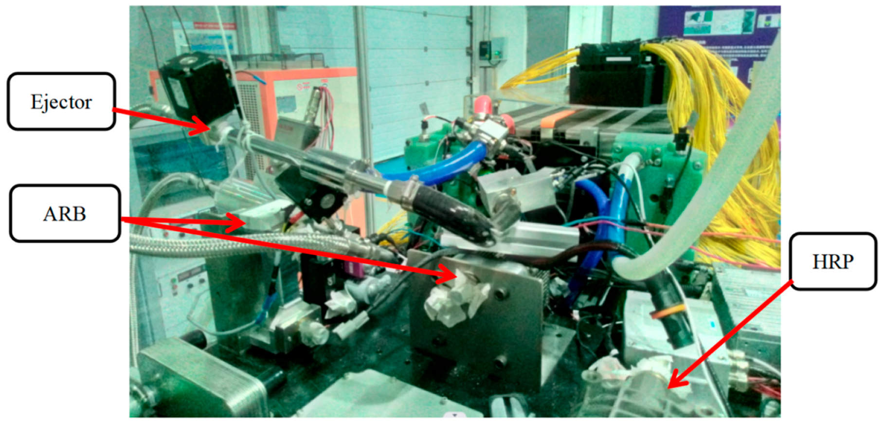
In this study, a 110 kW functional prototype PEMFC was built to facilitate the arrangement of different hydrogen recycling schemes. Pressure sensors were installed at the inlet and outlet of the stack to analyze and study the performance of the PEMFC. The schematic diagram of the functional prototype is shown in Figure 3.
The following can be seen in the figure: Ejector represents the ejector scheme; Anode Recirculation Blower (ARB) represents the HRP series ejector combination scheme; HRP stands for the hydrogen recirculation pump scheme. The brands and models of sensors used in this study are shown in Table 1.
3.2. Principles of Different Hydrogen Recycling Schemes
In this study, the HRS for PEFMCs mainly included three kinds: the HRP technology scheme, the ejector technology scheme, and the HRP series ejector combination scheme. Different hydrogen recycling technical schemes are shown in the figure below.
3.2.1. HRP Technical Scheme
Figure 4 shows the HRP technical scheme. The inlet of the HRP is connected to the outlet of the gas–water separator. The HRP pressurizes the stack anode outlet mixture gas and outputs it to the stack anode inlet pipeline, where it mixes with new hydrogen and enters the stack.
3.2.2. The HRP Series Ejector Combination Technical Scheme
Figure 5 illustrates the hydrogen recycling combination technical scheme of the HRP series ejector. The outlet of the HRP is connected to the secondary inlet port of the ejector, and the hydrogen mixture at the outlet of electric stack is pumped and compressed by the ejector, so that the mixture is pressurized and output to the hydrogen inlet line of stack, and then mixed with new hydrogen into the stack.
3.2.3. Ejector Technical Scheme
The hydrogen cycle technical scheme of the ejector is given in Figure 6. The primary inlet port of the ejector is equipped with a pressure-regulating proportional valve, and the new hydrogen passes through the primary inlet port of the ejector. The ejector changes the primary flow of the high-pressure fluid into a high-speed fluid when passing through the nozzle, and at the same time generates sufficient suction to extract the mixture from the hydrogen outlet and fully mix the new hydrogen and the mixture in the mixing zone of the ejector. After the gas flows to the ejector diffuser zone, the speed decreases and the pressure increases to realize the gas pressure boost. The pressurized gas is output to the anode inlet line of the stack and mixed with pure hydrogen from the hydrogen bottle before entering the stack.
4. Comparison and Analysis of Test Results
The performance test data of a PEMFC under the same stack operation conditions, based on three different hydrogen recycling technical schemes, were analyzed and compared. The main results are as follows.
4.1. Pressure Rise Comparison
For the statistical analysis of different hydrogen recycling technology schemes, a comparison of the rise in pressure rise in the anode inlet and outlet in a PEMFC stack is shown in Table 2 and Figure 7. In the figure, ARB is the HRP series ejector combination scheme, HRP refers to the hydrogen recirculation pump scheme, and Ejector represents the ejector scheme. The following observations can be made from the figure:
- (1)
- Compared with different current points, the polarization test of the PEMFC shows that the HRP series ejector combination scheme of differential pressure at the inlet and outlet of the anode stack is significantly greater than that of the technical schemes of the ejector and HRP;
- (2)
- At the 24 A current point, the pressure differential order is as follows: ARB scheme > HRP scheme > ejector scheme;
- (3)
- At the 48 A~240 A current points, the pressure differential at the inlet and outlet of the anode stack of the HRP scheme is similar to that of the ejector scheme;
- (4)
- At the 320 A current point, the order of differential pressure at the inlet and outlet is as follows: HRP series ejector combination scheme > HRP scheme > ejector scheme;
- (5)
- The anode inlet pressure fluctuation range is ±5 kPa, and the inlet and outlet pressure differential fluctuation ranges are ±5 kPa. However, the actual fluctuation range is ±2 kPa.
4.2. Comparison of Stack Voltage
- (1)
- At the 24 A current point, the following order in observed: the PEMFC stack voltage of the ejector scheme > HRP scheme > HRP series ejector combination scheme. This causes insufficient PEM humidity, mainly due to less water being generated at the low-power range. If the suction force of the HRS is too large, the insufficient water inside the stack will be sucked out, leaving the PEM extremely dry. This affects the proton conductivity of the ionic polymer and reduces the electrochemical reaction efficiency. Therefore, in the low-power region, HRSs with weak suction capacity are more necessary, such as ejectors. Excessively high suction capacity affects the efficiency of the PEMFC. So, the PEMFC efficiency of the ejector scheme is the highest in the low-power region, and that of the combination scheme is the lowest.
- (2)
- Between 48 A and 240 A, the stack voltage of the HRP scheme > HRP series ejector combination scheme > ejector scheme.
- (3)
- At 320 A, the following order in observed: the PEMFC stack voltage of the HRP series ejector combination scheme > HRP scheme > ejector scheme. At this current point, the ARB is still running, but the power is reduced to about 9 W. This shows that the high-pressure differential of the HRP series ejector combination scheme has a positive effect on the stack voltage at a high current point.
- (4)
- At the same current point, the stack voltage fluctuation range is ±1.5 V.
4.3. System Net Power Comparison
- (1)
- The net power trend of PEMFC systems is the same with different hydrogen recycling technology schemes. At the same current point, there is no significant difference in the net power of PEMFCs with different HRS schemes.
- (2)
- At low current points of 24 A, 48 A, and 72 A, the following order in observed: the PEMFC system net power of the ejector scheme > HRP scheme > HRP series ejector combination scheme.
- (3)
- At the 120 A current point, the PEMFC system net power of the ejector scheme, the HRP scheme, and the HRP series ejector combination scheme is almost the same.
- (4)
- Starting from 180 A, the power of the PEMFC system gradually becomes superior under the HRP series ejector combination scheme, especially at the 320 A current point, and the PEMFC system net power order is as follows: HRP series ejector combination scheme > HRP scheme > ejector scheme.
- (5)
- The net power of the PEMFC system in the HRP scheme, the ARB scheme, and the ejector scheme is highly consistent, indicating that the three technical schemes, such as the ejector, can be applied to a PEMFC hydrogen recirculation system.
- (6)
- At the same current point, the system net power fluctuation range is acceptable at ±0.5 kW.
5. Conclusions
In this work, the performance of PEMFCs based on three hydrogen recirculation technology schemes, namely HRP, ejector, and HRP series ejector, was studied. The system optimization calibration and debugging were carried out based on the three technical schemes. According to the statistical analysis of the test data, the following conclusions can be drawn:
- (1)
- For the pressure differential at the inlet and outlet of anode stack, the following order in observed: the HRP series ejector combination scheme > HRP scheme > ejector scheme. The pressure rise in the HRP series ejector combination scheme is significantly higher than that of the HRP scheme and the ejector scheme. The pressure rise in the HRP scheme is similar to that of the ejector scheme.
- (2)
- With different hydrogen recycling technology schemes, the stack voltage of the PEMFC is different at the same current point. At 24 A, the ejector scheme has the maximum voltage. Between 48 A and 240 A, the HRP scheme provides the maximum voltage. At 320 A, the electric stack voltage of the HRP series ejector combination scheme is the peak value. It indicates that there is a hydrogen recycling scheme suitable for different current points to make the voltage of the stack higher. In particular, the high pressure rise generated by the HRP series ejector combination scheme has a positive effect on the stack voltage at the high current point of 320 A.
- (3)
- Although the ejector performance is poor at a low flow rate, the ejector scheme can be applied to the low-power operating range of PEMFC. This is mainly due to less water being generated at a low-power range. If the suction force of the HRS is too strong, the insufficient water inside the stack will be sucked out, which will cause the PEM to become excessively dry. This affects the proton conductivity of the ionic polymer and reduces the electrochemical reaction efficiency. Therefore, in the low-power region, HRSs with weak suction capacity are more needed, such as ejectors. The low ejector capacity can ensure the required moist environment at the anode side of the stack is fulfilled. Excessively high suction capacity affects the efficiency of the PEMFC.
- (4)
- At the same current point, there is no obvious difference in the net power of PEMFCs with different HRS technology schemes; in particular, the HRP scheme and the ejector scheme have the same PEMFC net power, indicating that the power consumption generated by the HRP has little influence on the PEMFC net power.
- (5)
- The statistical analysis of the test data shows that the lower pressure rise at the low current point of 24 A has a positive effect on the system net power, while the higher pressure rise at the high current point of 320 A has a positive effect on the system net power.
- (6)
- According to the test, the three hydrogen recirculation schemes of ejector, HRP, and HRP series ejector meet the requirements of hydrogen recycling performance of a PEMFC. However, high suction capacity is required for high current points, and low suction capacity is required for low current points.
Author Contributions
Conceptualization, C.W. and L.W.; methodology, C.W. and L.W.; investigation, K.L.; data curation, J.L.; data analysis, Z.L. and C.Z.; writing—original draft, K.L.; writing—review and editing, C.W. and L.W. All authors have read and agreed to the published version of the manuscript.
Funding
The work was funded by the National Natural Science Foundation of China (Grant No. 52306256), China Postdoctoral Science Foundation (Grant No. 2023M732048), Shandong Postdoctoral Science Foundation (Grant No. SDBX2023007), and Key R&D projects of Shandong Province (Grant No. 2020CXGC010404).
Data Availability Statement
Data are contained within the article.
Conflicts of Interest
The collaboration between Shandong University and Weichai Power Co., Ltd., in this paper is based on the funding: The Key R&D projects of Shandong Province (Grant No. 2020CXGC010404). The ejector designed in Shandong University was tested by the functional prototype PEMFC in Weichai Power Co., Ltd. The author, Ms. Jingjing Li (Intermediate Engineer), was responsible for the commissioning, variable data collection, and analysis of PEMFCs based on different hydrogen cycle systems. The author, Mr. Zongji Li (Senior Engineer), provided a new idea for the design of a hydrogen cycle experiment scheme for PEMFCs in this paper, and was responsible for data analysis. The author, Mr. Chuanlong Zhang (Intermediate Engineer), was responsible for the design, commissioning, and evaluation of experimental results of PEMFCs based on different hydrogen circulation systems. All the authors participated in the writing and revision of this paper, ensuring the overall quality and accuracy of the paper. The authors declare no conflicts of interest.
References
- Song, Y.; Wang, X.; Wang, L.; Pan, F.; Chen, W.; Xi, F. A twin-nozzle ejector for hydrogen recirculation in wide power operation of polymer electrolyte membrane fuel cell system. Appl. Energy 2021, 300, 117442. [Google Scholar] [CrossRef]
- Sun, C.; Negro, E.; Vezzù, K.; Pagot, G.; Cavinato, G.; Nale, A.; Bang, Y.H.; Di Noto, V. Hybrid inorganic-organic proton-conducting membranes based on SPEEK doped with WO3 nanoparticles for in vanadium redox flow batteries. Electrochim. Acta 2019, 309, 311–325. [Google Scholar] [CrossRef]
- Kazim, A. Introduction of PEM fuel-cell vehicles in the transportation sector of the United Arab Emirates. Appl. Energy 2003, 74, 125–133. [Google Scholar] [CrossRef]
- Chen, H.C.; Song, Z.; Zhao, X.; Zhang, T.; Pei, P.C.; Liang, C. A review of durability test protocols of the proton exchange membrane fuel cells for vehicle. Appl. Energy 2018, 224, 289–299. [Google Scholar] [CrossRef]
- Alenazey, F.; Alyousef, Y.; AlOtaibi, B.; Almutairi, G.; Minakshi, M.; Cheng, C.K.; Vo, D.V.N. Degradation behaviors of solid oxide fuel cell stacks in steadyState and cycling conditions. Energy Fuels 2020, 34, 14864–14873. [Google Scholar] [CrossRef]
- Malik, V.; Srivastava, S.; Bhatnagar, M.K.; Vishnoi, M. Comparative study and analysis between Solid Oxide Fuel Cells (SOFC) and Proton Exchange Membrane (PEM) fuel cell—A review. Mater. Today Proc. 2021, 47, 2270–2275. [Google Scholar] [CrossRef]
- Du, Z.; Liu, Q.; Wang, X.; Wang, L. Performance investigation on a coaxial-nozzle ejector for PEMFC hydrogen recirculation system. Int. J. Hydrogen Energy 2021, 46, 38026–38039. [Google Scholar] [CrossRef]
- Liu, Y.; Tu, Z.K.; Chan, S.H. Applications of ejectors in proton exchange membrane fuel cells: A review. Fuel Process. Technol. 2021, 214, 106683. [Google Scholar] [CrossRef]
- Liu, Z.R.; Liu, Z.; Jiao, K.; Yang, Z.R.; Zhou, X.; Du, Q. Numerical investigation of ejector transient characteristics for a 130-kW PEMFC system. Int. J. Energy Res. 2020, 44, 3697–3710. [Google Scholar] [CrossRef]
- Yan, S.; Yang, M.; Sun, C.; Xu, S. Liquid water characteristics in the compressed gradient porosity gas diffusion Layer of proton exchange membrane fuel cells using the lattice boltzmann method. Energies 2023, 16, 6010. [Google Scholar] [CrossRef]
- Brunner, D.A.; Marcks, S.; Bajpai, M.; Prasad, A.K.; Advani, S.G. Design and characterization of an electronically controlled variable flow rate ejector for fuel cell applications. Int. J. Hydrogen Energy 2012, 37, 4457–4466. [Google Scholar] [CrossRef]
- Abbou, S.; Dillet, J.; Spernjak, D.; Mukundan, R.; Borup, R.L.; Maranzana, G.; Lottin, O. High potential excursions during PEM fuel cell operation with Dead-Ended anode. J. Electrochem. Soc. 2015, 162, F1212–F1220. [Google Scholar] [CrossRef]
- Wang, B.; Wu, K.; Xi, F.; Xuan, J.; Xie, X.; Wang, X.; Jiao, K. Numerical analysis of operating conditions effects on PEMFC with anode recirculation. Energy 2019, 173, 844–856. [Google Scholar] [CrossRef]
- Wang, X.; Lu, Y.; Zhang, B.; Liu, J.; Xu, S. Experimental analysis of an ejector for anode recirculation in a 10 kW polymer electrolyte membrane fuel cell system. Int. J. Hydrogen Energy 2022, 47, 1925–1939. [Google Scholar] [CrossRef]
- Liu, Z.; Chen, J.; Liu, H.; Yan, C.; Hou, Y.; He, Q.; Zhang, J.; Hissel, D. Anode purge management for hydrogen utilization and stackdurability improvement of PEM fuel cell systems. Appl. Energy 2020, 275, 115110. [Google Scholar] [CrossRef]
- Nikiforow, K.; Koski, P.; Ihonen, J. Discrete ejector control solution design, characterization, and verification in a 5 kW PEMFC system. Int. J. Hydrogen Energy 2017, 42, 16760–16772. [Google Scholar] [CrossRef]
- Han, J.; Feng, J.; Hou, T.; Peng, X. Performance investigation of a multi-nozzle ejector forproton exchange membrane fuel cell system. Int. J. Energy Res. 2021, 45, 3031–3048. [Google Scholar] [CrossRef]
- Zhang, G.B.; Jiao, K. Multi-phase models for water and thermal management of protonexchange membrane fuel cell: A review. J Power Sources 2018, 391, 120–133. [Google Scholar] [CrossRef]
- Lin, R.; Li, B.; Hou, Y.P.; Ma, J.M. Investigation of dynamic driving cycle effect on performance degradation and micro-structure change of PEM fuel cell. Int. J. Hydrogen Energy 2009, 34, 2369–2376. [Google Scholar] [CrossRef]
- Patel, P.P.; Velikokhatnyi, O.I.; Ghadge, S.D.; Jampani, P.H.; Datta, M.K.; Hong, D.; Poston, J.A.; Manivannan, A.; Kumta, P.N. Highly active robust oxide solid solution electro-catalysts for oxygen reduction reaction for proton exchange membrane fuel cell and direct methanol fuel cell cathodes. Int. J. Hydrogen Energy 2017, 42, 24079–24089. [Google Scholar] [CrossRef]
- Merritt, R.D.; Gorbell, B.N. Electrochemical Fuel Cell System with a Regulated Vacuum Ejector for Recircualtion of the Fluid Fuel Stream. U.S. Patent 5441821, 15 August 1995. [Google Scholar]
- Maghsoodi, A.; Afshari, E.; Ahmadikia, H. Optimization of geometric parameters for design a high-performance ejector in the proton exchange membrane fuel cell system using artificial neural network and genetic algorithm. Appl. Therm. Eng. 2014, 71, 410–418. [Google Scholar] [CrossRef]
- Yin, Y.; Fan, M.Z.; Jiao, K.; Du, Q.; Qin, Y. Numerical investigation of an ejector for anode recirculation in proton exchange membrane fuel cell system. Energy Convers. Manag. 2016, 126, 1106–1117. [Google Scholar] [CrossRef]
- Kim, M.; Sohn, Y.J.; Cho, C.W.; Lee, W.Y.; Kim, C.S. Customized design for the ejector to recirculate ahumidified hydrogen fuel in a submarine PEMFC. J. Power Sources 2008, 176, 529–533. [Google Scholar] [CrossRef]
- Dadvar, M.; Afshari, E. Analysis of design parameters in anodic recirculation system based on ejector technology for PEM fuel cells: A new approach in designing. Int. J. Hydrogen Energy 2014, 39, 12061–12073. [Google Scholar] [CrossRef]
- Wang, X.H.; Xu, S.C.; Xing, C.M. Numerical and experimental investigation on an ejector designed for an 80kW polymer electrolyte membrane fuel cell stack. J. Power Sources 2019, 415, 25–32. [Google Scholar] [CrossRef]
- Badami, M.; Mura, M. Theoretical model with experimental validation of a regenerative blower for hydrogen recirculation in a PEM fuel cell system. Energy Convers. Manag. 2010, 51, 553–560. [Google Scholar] [CrossRef]
- Gao, Y.; Lin, M. Research on the performance characteristics of hydrogen circulation pumps for PEMFC vehicles. Int. J. Hydrogen Energy 2024, 50, 1255–1272. [Google Scholar] [CrossRef]
- Wu, C.W.; Zhang, W.; Han, X.; Zhang, Y.X.; Ma, G.J. A systematic review for structure optimization and clamping load design of large proton exchange membrane fuel cell stack. J. Power Sources 2020, 476, 228724. [Google Scholar] [CrossRef]
Figure 1.
Hydrogen recirculation system based on an HRP.

Figure 2.
Working principle of a PEMFC.

Figure 3.
Functional prototype.

Figure 4.
Hydrogen cycle scheme of HRP.

Figure 5.
Hydrogen cycle scheme of HRP series ejector.

Figure 6.
Hydrogen cycle scheme of ejector.

Figure 7.
Differential pressure comparison at inlet and outlet of anode stack with different HRSs.

Figure 8.
Stack voltage comparison of different HRSs.

Figure 9.
Net power comparison of PEMFCs with different HRSs.


Table 1.
Sensor parameters.
| Brand | Range | Accuracy | Mode of Signal | |
|---|---|---|---|---|
| Medium-pressure sensor | Sensata | 0–14 barg | ±1% Vcc | Type of voltage |
| Low-pressure sensor | Sensata | 0.5–4 barg | ±2% Vcc | Type of voltage |
| Temperature sensor | ShengBang | −40–120 °C | ±0.1 °C | Type of current |
| Current voltage sensor | VOLT | Current: ±600 A | ±0.5% | CAN |
| Voltage: 0–900 V | ±1% |
Table 2.
Differential pressure data comparison of different HRSs.
| Current (A) | HRB Differential Pressure (bar) | ARB Differential Pressure (bar) | Ejector Differential Pressure (bar) |
|---|---|---|---|
| 24 | 0.07 | 0.11 | 0.05 |
| 48 | 0.09 | 0.12 | 0.08 |
| 72 | 0.10 | 0.14 | 0.11 |
| 120 | 0.13 | 0.18 | 0.13 |
| 180 | 0.16 | 0.21 | 0.15 |
| 240 | 0.17 | 0.25 | 0.17 |
| 320 | 0.24 | 0.28 | 0.2 |
Table 3.
Stack voltage data comparison of different HRSs.
| Current (A) | HRB Stack Voltage (V) | ARB Stack Voltage (V) | Ejector Stack Voltage (V) |
|---|---|---|---|
| 24 | 445.29 | 443.09 | 454.6 |
| 48 | 449.35 | 445.74 | 443.4 |
| 72 | 435.71 | 432.28 | 430.8 |
| 120 | 414.36 | 410.57 | 409 |
| 180 | 403.14 | 399.03 | 396 |
| 240 | 393.23 | 389.07 | 386 |
| 320 | 376.90 | 377.06 | 371.4 |
Table 4.
System net power data comparison of different HRSs.
| Current (A) | HRB System Net Power (kW) | ARB System Net Power (kW) | Ejector System Net Power (kW) |
|---|---|---|---|
| 24 | 9.83 | 9.59 | 10.4 |
| 48 | 20.17 | 19.94 | 20.3 |
| 72 | 29.37 | 29.05 | 29.4 |
| 120 | 46.59 | 46.10 | 46.2 |
| 180 | 66.31 | 65.96 | 65.5 |
| 240 | 84.52 | 84.12 | 83.2 |
| 320 | 104.83 | 105.55 | 103.8 |
Disclaimer/Publisher’s Note: The statements, opinions and data contained in all publications are solely those of the individual author(s) and contributor(s) and not of MDPI and/or the editor(s). MDPI and/or the editor(s) disclaim responsibility for any injury to people or property resulting from any ideas, methods, instructions or products referred to in the content. |
© 2024 by the authors. Licensee MDPI, Basel, Switzerland. This article is an open access article distributed under the terms and conditions of the Creative Commons Attribution (CC BY) license (https://creativecommons.org/licenses/by/4.0/).
Share and Cite
MDPI and ACS Style
Li, K.; Wang, C.; Li, J.; Wang, L.; Li, Z.; Zhang, C. Experimental Investigation into the Performance of PEMFCs with Three Different Hydrogen Recirculation Schemes. Inventions 2024, 9, 33. https://doi.org/10.3390/inventions9020033
AMA Style
Li K, Wang C, Li J, Wang L, Li Z, Zhang C. Experimental Investigation into the Performance of PEMFCs with Three Different Hydrogen Recirculation Schemes. Inventions. 2024; 9(2):33. https://doi.org/10.3390/inventions9020033
Chicago/Turabian StyleLi, Kejing, Chen Wang, Jingjing Li, Lei Wang, Zongji Li, and Chuanlong Zhang. 2024. "Experimental Investigation into the Performance of PEMFCs with Three Different Hydrogen Recirculation Schemes" Inventions 9, no. 2: 33. https://doi.org/10.3390/inventions9020033