
Coordinated, Centralized, and Simultaneous Control of Fast Charging Stations and Distributed Energy Resources


1
Graduate Program in Electrical Engineering, Universidade Federal de Minas Gerais, Av. Antônio Carlos 6627, Belo Horizonte 31270-901, MG, Brazil
2
Department of Electrical Engineering, Universidade Federal de Minas Gerais, Belo Horizonte 31270-901, MG, Brazil
3
Department of Electronics Engineering, Universidade Federal de Minas Gerais, Belo Horizonte 31270-901, MG, Brazil
*
Author to whom correspondence should be addressed.
Inventions 2024, 9(2), 35; https://doi.org/10.3390/inventions9020035
Submission received: 23 February 2024
/
Revised: 18 March 2024
/
Accepted: 19 March 2024
/
Published: 25 March 2024
(This article belongs to the Special Issue Recent Advances and Challenges in Emerging Power Systems)
Abstract
:The growing penetration of fast charging stations (FCSs) to electric vehicles (EVs) and distributed energy resources (DERs) in the electrical power system brings technical issue changes in the voltage profile throughout grid nodes and feeder current overload. The provision of ancillary services by DERs and FCSs arises as an appealing solution to reduce these adverse effects, enhancing the grid hosting capacity. The control of microgrids is essential for the coordinated implementation of these services. Although microgrid control is widely applied to DERs, few studies address the coordinated control of DERs and FCSs to obtain benefits for the electrical power system. This paper proposes a coordinated and simultaneous control of DERs and FCSs based on the power-based control (PBC) strategy, efficiently exploiting FCSs in a microgrid model previously unaddressed in the literature. The results show that, with the coordinated control of DERs and FCSs, the control of the power flow in a minigrid (MG) is achieved both in moments of high generation and in moments of high load, even with the maximum operation of DERs. This method allows for the maintenance of voltage levels within values considered acceptable by technical standards (above 0.93 pu). The maintenance of voltage levels is derived from reducing the overload on the point of common coupling (PCC) of the minigrid by 28%, performing the peak shaving ancillary service. Furthermore, the method allows for the control of zero power flow in the PCC of the minigrid with the upstream electric grid in periods of high generation, performing the ancillary service of valley filling. The method performs this control without compromising vehicle recharging and power dispatch by DERs.
1. Introduction
The emission of polluting gases into the atmosphere has been the subject of debates and actions by several countries and industries. In humans, pollution can cause short-term effects such as eye, throat, and nose irritation; headaches; nausea; and can worsen cases of diseases such as bronchitis and pneumonia. Long-term effects may include heart disease, lung cancer, and pulmonary emphysema [1]. According to a study by the University of Chicago, the life expectancy of the inhabitants of South Korea is 1.4 years lower due to air pollution, as the entire South Korean population lives in areas with pollution above the levels recommended by the World Health Organization [2]. The effects on the environment are also significant, leading to soil pollution and the mortality of plants and animals thanks to polluting compounds such as sulfur dioxide and nitrogen oxides. Finally, a possible acceleration in Earth’s warming is credited to carbon dioxide (due to its ability to retain heat in the atmosphere) and other gases such as methane [1].
Several governments have created laws and tax incentives to encourage solutions that reduce such emissions. Since the 1970s, the USA has followed the Clean Air Act, which regulates atmospheric emissions from stationary sources such as industries and mobile sources (i.e., combustion vehicles) [3]. Members of the European Union must meet obligations to reduce air pollution based on the National Emission Reduction Commitments Directive (NECD) [4].
Both the USA and the European Union classify the road transport sector as a high source of polluting gas emissions into the atmosphere. Combustion vehicles are responsible for 27% of polluting gas emissions in the USA [5]. One of the ways to reduce the gas emissions caused by the vehicle fleet during its use is through electrification, whether through hybrid or fully electric vehicles (EVs).
However, consumer adoption of EVs is essential. One of consumers’ biggest concerns regarding EVs is recharging time and vehicle charger infrastructure [6,7,8]. Despite the advantage of being able to fully recharge overnight with low-power chargers, vehicles used in public and individual passenger transport require recharging at shorter periods because they cover a great distance during the day, even in urban regions. Typically, the service, policing, emergency, and cargo transportation sectors cannot rely on slow recharges.
Based on this, the Federal Highway Administration (FHWA), an agency linked to the United States Department of Transportation, proposed minimum standards for the country’s road network [9] through the National Electric Vehicle Infrastructure Formula Program. The document suggests that there be four charging stations with a minimum power of 150 kW at each charging location, with a minimum distance of 80 km between the stations and less than 2 km from highways. High-power charging stations are called fast charging station (FCSs).
Furthermore, [9] suggests the installation of 500,000 chargers by 2030. According to data from the Alternative Fuels Data Center, an organization linked to the US Department of Energy, there were around 40,000 DC fast charger ports across the country in February 2024, with approximately 27% of them being in the state of California [10]. By 2022, the number of DC fast chargers installed in the USA was around 6600, a smaller number than in countries such as Germany (12,000) and France (9000) [11], even though they have more vehicles [12] and greater territorial extension than the countries cited. China has around 760,000 fast chargers, but around 70% are installed in just 10 of the country’s 22 provinces [11].
In addition to voltage disturbances [13,14] and high harmonic content [15,16,17,18,19], the most significant impact of inserting electric vehicle chargers is the overload of the electrical power system [20,21,22,23]. To accommodate the rise in electricity consumption, it is also necessary to generate more energy. As the energy sector is also one of the sectors that emits the most polluting gases into the atmosphere, the construction of polluting plants, such as coal or gas thermoelectric plants, has been discouraged by agreements and laws [24].
Among all the forms of energy generation, two have received the most attention: solar and wind. Due to not emitting polluting gases during their generation and the usage of renewable resources, these two sources have been receiving incentives in several countries such as the USA [25], Brazil [26], China [27], and the European Union [28].
The advantages of solar energy generation are explained by the easiness to install for small energy consumers, transforming them into prosumers. Photovoltaic modules can be installed on the roofs of houses, buildings, and condominium areas, reducing the energy costs of these consumers. Thus, the concept of distributed generation represents a transformative shift away from the conventional methods of energy production.
With distributed generation, new challenges arise for electrical power systems since the systems were originally designed to deal with generation far from large electrical energy consumption centers. Distributed generation aggravates issues related to voltage and frequency regulation, generation intermittency, and feeder overload [29,30]. Changes to electrical infrastructure through cable reconductoring and equipment replacement are alternatives, but they are complex and costly. Therefore, one of the alternatives that arise to reduce these impacts on the electrical power system is the control of microgrids capable of integrating all these new players into the electrical power system.
Despite the relevance of the subject, few studies discuss the simultaneous coordinated control of FCSs and distributed energy resources (DERs), which is highly desired in the aforementioned scenario. When it comes to providing ancillary services between FCSs and DERs, many works address vehicle-to-grid (V2G) strategies [19,31,32,33,34,35,36,37,38,39,40,41,42,43,44]. However, in fast charging applications, V2G is not an interesting alternative from the vehicle owner’s point of view since the reverse power flow would increase the vehicle’s total recharging time. Therefore, it is not common to find works that involve V2G and FCS.
Table 1 summarizes a comparative analysis of adherent state-of-the-art works that use FCSs to provide ancillary services, categorizing them according to voltage level, ancillary service category, control of DERs and FCSs, and the control architecture of DERs or FCSs according to [45]. None of these strategies encompass the simultaneous control of FCSs and DERs. Some use strategies with decentralized architectures that cannot compose an advanced minigrid.
To the best of the authors’ knowledge, no works were found that simultaneously control the DERs power dispatch and the FCSs power absorption. Thus, this paper proposes a simultaneous control of these two entities, allowing better grid power quality and increased operational flexibility due to controllability at different points in the network.
The main contribution of this paper is a novel method for simultaneous coordinated control between fast charging stations (FCSs) and distributed energy resources (DERs) in a minigrid (MG), categorizing it as an advanced minigrid [57]. An MG is a set composed of one or more LV microgrids with DERs connected to medium voltage through transformers, loads, generators, and FCSs also connected directly to medium voltage. This approach consists of hierarchically interconnecting smaller microgrids with the larger minigrid. Figure 1 shows the MG used in this paper, with a minigrid central controller (MGCC), microgrid central controllers (GCCs), and fast charging station central controllers (FCSCCs). The objective of this control is to reduce or increase consumption at charging stations depending on the established boundary conditions to maintain power levels at the MG PCC that guarantee the reliability of the grid power quality parameters.
This paper is divided as follows: after the Introduction, Section 2 presents the literature review about the PBC method. Section 3 presents the proposed strategy and the methodology and methods used to validate the concept of the control proposal. Section 4 presents the simulation results. Section 5 presents the results and is followed by Section 6, which concludes this work.
2. Literature Review
Power-Based Control
First presented by [58] for single-phase low-voltage microgrids, other works improve the power-based control (PBC) strategy over time. Table 2 presents work involving PBC improvements, variation, or specific applications.
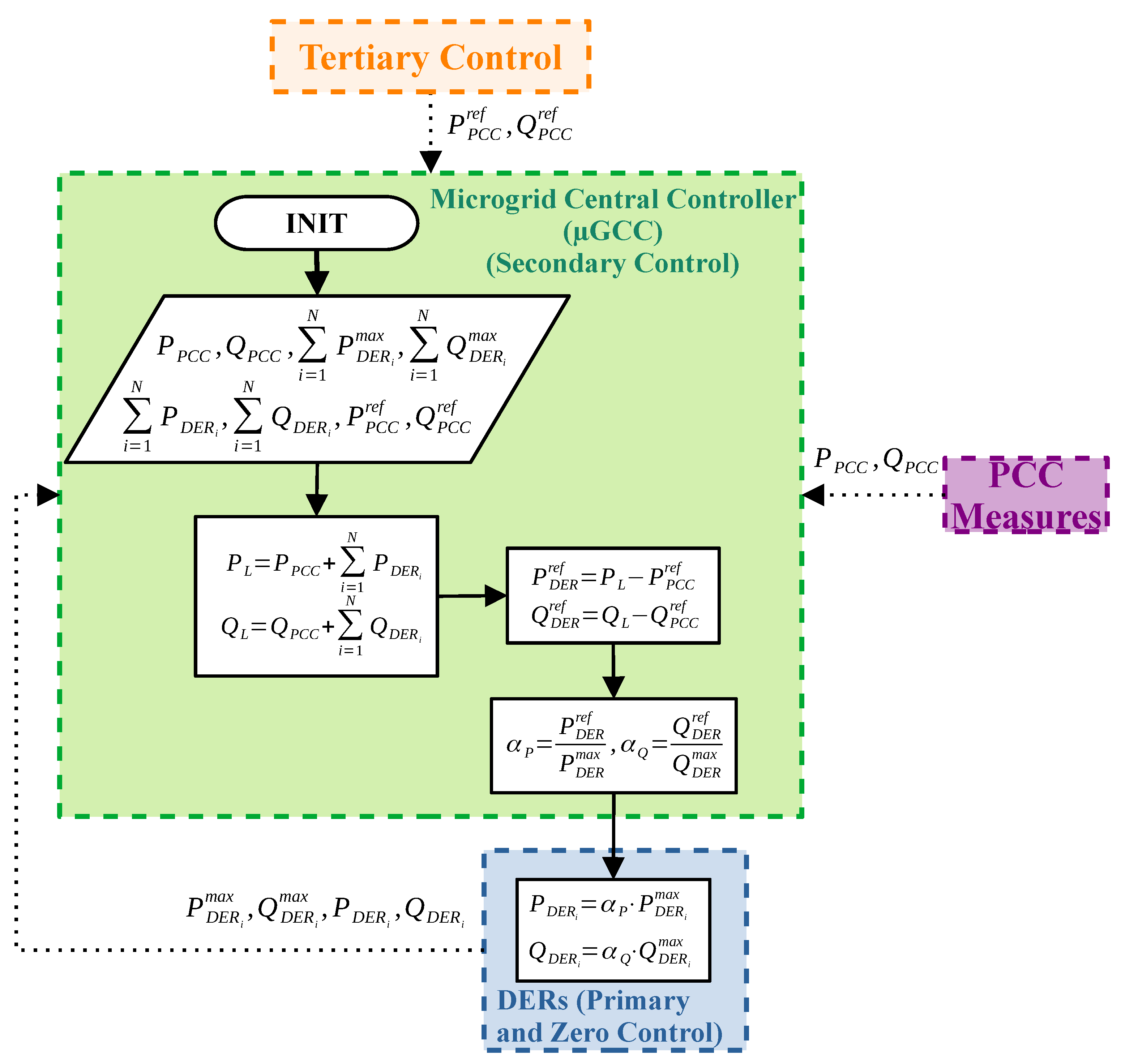
Figure 2 shows a schematic of the original PBC algorithm [58]. The PBC regulates, through a central controller, the dispatch of active and reactive power between a microgrid and PCC performing a proportional power sharing between DERs. To do so, the central controller uses the following measurements and parameters:
- The active power () and reactive power () in the PCC of the microgrid in the current cycle ℓ.
- The sum of the maximum active () and reactive () powers that each DER can dispatch in the current cycle ℓ.
- The sum of active () and reactive () powers dispatched by DERs in the current cycle ℓ.
- The active power references () and reactive () desired in the PCC in the next cycle ().
With these measurements and parameters, it is possible to estimate the active power load () and reactive power load () of the microgrid through (1) and (2), respectively. The ℓ cycle is the control cycle of the algorithm. The power load of the microgrid includes the entities that consume energy and generate energy that does not obey the central controller; that is, the non-dispatchable DERs:
From (1) and (2), the desired power to be dispatched by the DERs in the next control cycle is defined according to (3) and (4). For instance, Equation (3) defines the active power reference for the set of DERs for the next cycle, while (4) expresses the reactive power reference:
For there to be proportional power sharing between the DERs of the microgrid, the powers obtained in (3) and (4) are divided, respectively, by the active and reactive power maximums that each DER can dispatch at that moment. In this way, the coefficients and are obtained, expressed by (5) and (6), respectively:
Figure 2.
Schematic of the original PBC algorithm.

The lower limit for the coefficient is −1, considering that the DER allows for control of the absorption of its nominal power through the central controller. The upper limit for is one, which means that the DER dispatches all the available power. The coefficient also has the same lower and upper limits, with the lower limit being the maximum inductive reactive power that the DER can dispatch and the upper limit being the maximum capacitive reactive power that the DER can deliver. Current direction conventions and the position of current meters can modify the meaning of the limits of the active and reactive power coefficients.
All participant DERs of the microgrid control receive both coefficients. Each DER will carry out a dispatch proportional to its power capacity, and the central controller will be able to regulate the power dispatch in the PCC more efficiently, reducing losses in the distribution system [58].
The advantages of PBC as a microgrid control algorithm are its simplicity, good performance compared to strategies such as droop control, and its model-free approach (i.e., it is not necessary to know the grid parameters to control the microgrid, commonly required in optimal control approaches [58]). The disadvantages of PBC are mainly associated with its centralized nature, such as its difficulty in scalability and dependence on the communication link. Another disadvantage is the steady-state error in cases of non-idealities in the communication link and power measurements carried out by DERs, which can be corrected by using classical control strategies, such as proportional-integral (PI) controllers [68].
3. Methodology and Methods
3.1. Proposed Power-Based Control Applied to Fast Charging Stations
As highlighted, the PBC algorithm is limited to the maximum power that DERs can dispatch to the grid. Therefore, it is not possible to control the power dispatch in the PCC of the minigrid at the desired values if there is a violation of the lower or upper limits of the coefficients and .
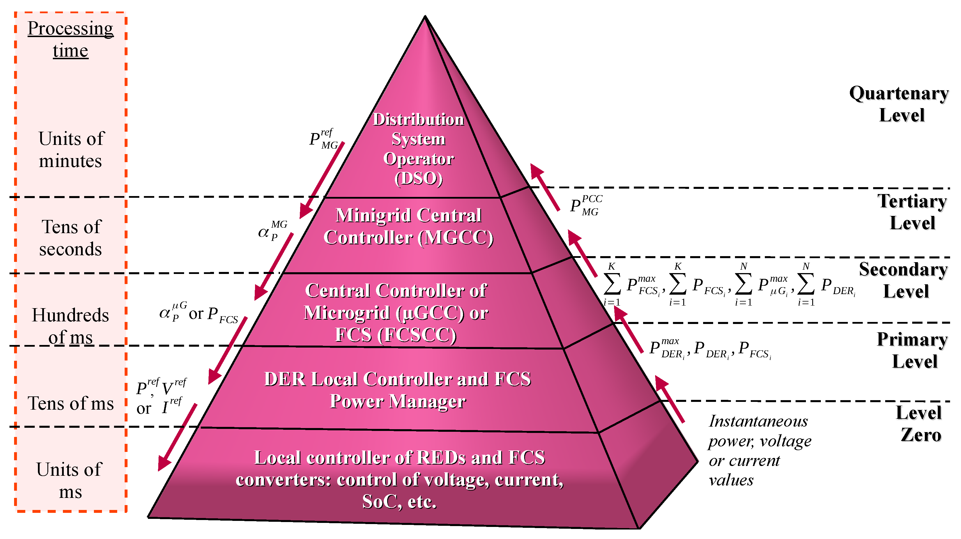
The proposed method herein takes advantage of the traditional PBC formulation and improves it for applications during violation of the lower and upper limits of the coefficient in a minigrid (MG). The superscript index of the coefficient determines whether it comes to the minigrid (MG) or microgrid (G) controller. The proposed control will act at the tertiary level, controlling the power flow in the PCC of MGs with the upstream grid. Figure 3 shows the hierarchy between controllers. This control hierarchy has the following levels:
- Quartenary level: Composed of a distribution system operator (DSO). The electric power utility or a control entity that covers a set of minigrids controls the DSO, responsible for determining the power references for the MGCC. With the absence of the DSO, power references can be determined locally by the MGCC based on the integrity of the voltage levels (as in the work of [67]) and grid frequency or based on financial parameters involving energy consumption from the upstream grid.
- Tertiary level: Composed of an MGCC, responsible for controlling the power flow from the MG to the upstream network. Responsible for sharing and processing information from the microgrid central controller (GCC), FCSCC, and DSO. It is responsible for sending the coefficient to the GCC and FCSCC and receives, from the DSO, the desired power reference for the PCC of the MG.
- Secondary level: Composed of the GCC or FCSCC, responsible for controlling the power flow from the microgrid/FCS with the upstream network. It is responsible for sharing and processing information from the MGCC and local controllers of the DER/energy managers of the FCS. Using the coefficient , you must determine your own coefficient and send it to the DERs or FCS energy managers.
- Primary level: Composed of DER local controllers and the FCS energy manager. In the case of the FCS, it may be part of the FCSCC. Responsible for sharing and processing information with GCC/FCSCC and with the DER or FCS converters. It is he who sends the power, current, or voltage references to the DER or FCS converters.
- Level zero: Composed of the local controllers of the DER and FCS converters. They share information with the DER local controller and are responsible for dispatching/absorbing power to the grid.
In addition to the DER as actuators contributing to the injection of active power, the algorithm also uses the charging stations to control the active power at the PCC. This configuration is typical of a multiple inputs single output (MISO) system.
One of the alternatives for controlling MISO systems is to carry out proportional control between the actuators, the same way as PBC concerning DERs. As FCSs are essentially controllable system loads, participation in control will be through the reduction in power absorbed from their respective upstream connection points.
Figure 4 presents a power control diagram with the DERs and FCSs as actuators. Based on the power reference and the power measured in the PCC, the control algorithm establishes the power reference to be injected by the DER and the power reference to be absorbed by the FCS. Other non-controllable agents on the grid, whether loads or generators, are a disturbance of the controlled variable (PCC power).
Figure 3.
Control hierarchy of the proposed system.

Figure 4.
Simplified power control scheme in the PCC of the medium-voltage microgrid through shared control.
Figure 4.
Simplified power control scheme in the PCC of the medium-voltage microgrid through shared control.

Therefore, the control algorithm must be able to process the measured power and power reference information at the MG PCC to send commands to the actuators (microgrids and FCS). Figure 5 shows the algorithm of the proposed system. Since the active and reactive power amounts are orthogonal to each other (i.e., decoupled), analyses can be conducted individually for each power term.
In the adaptation of PBC proposed in this work, the MGCC requires the following measurements and parameters to send commands to the actuators:
- The active power () in the PCC of the minigrid in the current cycle ℓ. This information is collected locally by MGCC, which is connected to PCC.
- The sum of the maximum active powers () that each microgrid can dispatch in the current cycle ℓ. N is the number of microgrids present in the minigrid. This power is the sum of the maximum powers that DERs can dispatch. This information is sent by GCCs to the MGCC over a low bandwidth (according to the US Federal Communications Commission [69], communication links below 25 Mbps are low-bandwidth links) and long-range communication links;
- The sum of active powers () dispatched by the DERs of the microgrids in the current cycle ℓ. N is the number of microgrids present in the minigrid. This information is sent by the DERs to GCCs through a low-bandwidth communication link, such as the radio data system (RDS). Subsequently, these data are sent to the MGCC through a low-bandwidth and long-range communication link;
- The desired active power reference in the PCC of the minigrid in the next cycle () (). This information is sent by the DSO to the MGCC over a low-bandwidth and long-range communication link;
- The sum of the maximum active powers () that each charging station can absorb in the current cycle ℓ. K is the number of FCSs present in the minigrid. This information is sent by FCSCCs to the MGCC over a low bandwidth and long-range communication link;
- The sum of active powers () absorbed by the charging stations in the current cycle ℓ. K is the number of FCSs present in the minigrid. This information is sent by FCSCCs to the MGCC over a low bandwidth and long-range communication link.
The first novelty is to calculate the total maximum power of the system, as shown in (7). With this, there will be proportionality between the power dispatch of the DERs and the increase or reduction in consumption by the FCSs:
The second novelty is to calculate the power load of the minigrid, initially presented in Equation (1) for microgrids. With FCSs, it is possible to account for their contributions, as expressed in Equation (8):
From (8), it is possible to define the desired global power to be dispatched/absorbed in the next control cycle by the set of DERs of microgrids and FCSs by using Equation (9):
To achieve proportional power sharing between DERs and the reduction in the active power consumed between the FCSs, the global power in (9) is divided by the maximum active power of the minigrid in (7). Thus, the coefficient expressed in (10) is obtained:
Based on the , each GCC will calculate its respective and send it to the DERs, according to (11). In turn, each DER will carry out the dispatch by (12). The FCSs defines the power to be demanded based on (13):
Therefore, for the system to operate properly, there will be a proportionality between the power dispatched by the DERs and the power reduced by the FCSs. The charging station can operate with negative coefficients, resulting in absorbed powers superior to the maximum (for example, above the contracted demand).
3.2. Minigrid Parameters
A simulation of a medium-voltage minigrid, shown in Figure 1, containing three microgrids, two fast charging stations, a load, and a non-dispatchable distributed generator, is performed by using MATLAB/Simulink R2022b® software.
There is an external load on the PCC of the minigrid. Current sources, defined through the voltage measured at their connection point and the power standard, represent the grid elements modeled only with active power.
The MGCC can disconnect the minigrid from the upstream grid and be equipped with a grid-forming converter, maintaining the characteristics of an advanced minigrid. The grid-forming converter can also be performed by other elements, such as the internal generator (if there is a storage system) or some FCS. This work does not address the islanded mode of this minigrid nor the characterization of the grid-forming converter. Ref. [70] discusses a converter capable of operating as a grid-forming converter without injecting harmonics into the electrical grid. Ref. [71] presents an alternative to FCSs with this converter that can be used as a grid-forming unit.
Table 3 presents the characteristics of the grid elements. The FCSs are composed of a battery energy storage system (BESS) with an energy of 646.4 kWh capable of charging three 250 kW chargers simultaneously for 50 min. The power of the chargers is typical of commercial chargers such as the Tesla Supercharger V3 [72]. Table 4 presents the characteristics of the cables, represented by the grid impedances. The chosen cables operate with voltages between 8.7 kV and 15 kV. In Brazil, the typical voltage of distribution systems is 13.8 kV.
The LV Microgrid 1 () emulates a neighborhood with a predominance of houses equipped with photovoltaic systems. Among the dispatchable DERs, there is a fixed base of 30 kWp and 50 kWp of generation from solar energy, which varies throughout the day. Figure 6 shows the profiles of the dispatchable and non-dispatchable DERs and the load of the LV Microgrid 1.
A medium-sized supermarket in Brazil is the basis for the LV Microgrid 2 () data. Ref. [74] present, in their work, consumption data from this supermarket. Generation data were estimated based on its total area (5962 m2), considering an average generation of 0.15 kWp/m2 [75]. Among the dispatchable DERs, there is a fixed base of 20 kWp and 40 kWp of generation from variable solar energy throughout the day. Figure 6 shows the profiles of dispatchable and non-dispatchable DERs and the load of the LV Microgrid 2.
The LV Microgrid 3 () emulates a condominium with a large area dedicated to its photovoltaic plant with high generation and low consumption. Among the dispatchable DERs, there is a fixed base of 30 kWp and 50 kWp of generation from solar energy, which varies throughout the day. Figure 7 presents the profiles of the dispatchable and non-dispatchable DERs and the load of the LV Microgrid 3. Figure 7 also presents internal and external load profiles and the internal generator based on the photovoltaic energy.
3.3. Evaluated Scenarios and Metrics
There are six possibilities for the operation of the minigrid entities. They are:
- Without FCSs: in this condition, there are no FCSs on the grid.
- With FCSs not participating in the proposed control: Charging stations operate as constant loads due to the internal management algorithm at all times. FCSs are not controlled by the MGCC.
- With FCSs participating in the proposed control: charging stations operate as constant loads due to the internal management algorithm. Upon receiving a control command, they start to control the energy demand according to the complement of the coefficient (). Therefore, FCSs are controlled by MGCC.
- Without DERs: in this condition, there is no type of distributed generation on the grid; that is, the grid does not have dispatchable DERs nor non-dispatchable DERs.
- Without dispatchable DERs: All the DERs in the network dispatch all available active power. In this condition, the DERs are not controlled by the MGCC.
- With dispatchable DERs: In this condition, the non-dispatchable DERs dispatch all available active power, and the dispatchable DERs dispatch power according to the index . The MGCC commands dispatchable DERs.
It will be considered that all FCSs have their own BESS and an internal energy-management algorithm that maintains the grid power demand at a constant value within the BESS energy absorption and dispatch limits. About the DERs of each microgrid, the following conditions will be considered:
- The non-dispatchable DERs do not have energy storage. Generation from photovoltaic modules is the basis for all energy dispatch;
- The dispatchable DERs have energy storage;
- For dispatchable DERs, it is considered that there is an internal energy-management system that manages the recharging of the batteries based on the generation of the photovoltaic modules. This management will guarantee a fixed installment that can always be dispatched, even at times when there is no generation (e.g., at night). Some works suggest energy-management algorithms for DERs [63,76,77,78].
The possibilities for the operation of the minigrid elements allow for the evaluation of nine different scenarios, in which it is possible to evaluate the effect of the presence or absence of the proposed control. Table 5 presents the nine possible scenarios.
Scenario 1 is the base scenario, in which there are no DERs and FCSs. This scenario sketches the network with its initial design without overloads and adequate voltage levels. Scenario 2 presents the insertion of non-dispatchable DERs without power control. This scenario can increase voltage levels, especially at the DERs’ connection point. Scenario 3 presents the insertion of non-dispatchable and dispatchable DERs. This scenario allows for greater operational flexibility of the grid with dispatching power from the minigrid to the upstream grid.
Scenario 4 presents the insertion of FCSs without the insertion of DERs. This scenario allows for the evaluation of a network without distributed generation and with large passive loads such as FCSs. Scenario 5 presents the insertion of non-dispatchable DERs and FCSs. This scenario relieves the grid during periods of high generation but does not relieve it during periods of low generation. Scenario 6 presents the insertion of non-dispatchable and dispatchable DERs and FCSs. This scenario relieves the grid during periods of high generation without dispatching power from the minigrid to the upstream grid.
Scenario 7 presents the insertion of FCSs controlled by the proposed algorithm without the insertion of DERs. In this scenario, the network is relieved during periods of high consumption with high use of the BESSs of the FCSs. Scenario 8 presents the insertion of FCSs controlled by the proposed algorithm with the insertion of non-dispatchable DERs. This scenario allows for the reduction in the use of BESSs from FCSs but with power dispatch from the minigrid to the upstream network.
Scenario 9 bases this work, in which both the FCS and dispatchable DERs are controlled by using the proposed algorithm. In this scenario, relief from the electrical grid is expected at times of high load with low use of the BESSs of the FCSs and with zero-flow control of the power dispatch between the minigrid and the upstream electrical grid.
The control algorithm is activated during the periods shown in Table 6. The period from 10 a.m. to 2 p.m. has the highest solar generation. The objective is to evaluate the scenarios against a zero power reference in the medium-voltage PCC. The purpose is to evaluate whether the control can not dispatch power to the upstream grid, realizing an ancillary service of valley filling.
Another ancillary service performed by the proposed control is peak shaving. One of the metrics to establish the desired power in the PCC of a minigrid is the voltage level. A reference power of 1550 kW was defined in the activation period from 6 p.m. to 10 p.m. so that the voltage in the PCC does not exceed the values considered appropriate by Module 8 of Procedimento de Distribuição de Energia Elétrica no Sistema Elétrico Nacional (PRODIST) [79] from Agência Nacional de Energia Elétrica (ANEEL), the regulatory agency for the Brazilian electrical system. Another way to define this power is online, to always keep the voltage within the limits considered appropriate [67]. Voltage levels are also influenced by the reactive power in the PCC, which can change the active power reference levels to maintain voltage at appropriate levels. Table 7 presents the steady-state voltage rating ranges for connection points with a nominal voltage between 2.3 kV and 69 kV.
4. Simulation Results
The nine scenarios proposed in Table 5 will be evaluated. With this, it is possible to emphasize the disadvantages of each scenario and verify the performance of the control proposed in the last scenario, showing its relevance to reducing overload problems and precarious voltage levels.
4.1. Scenarios without FCS
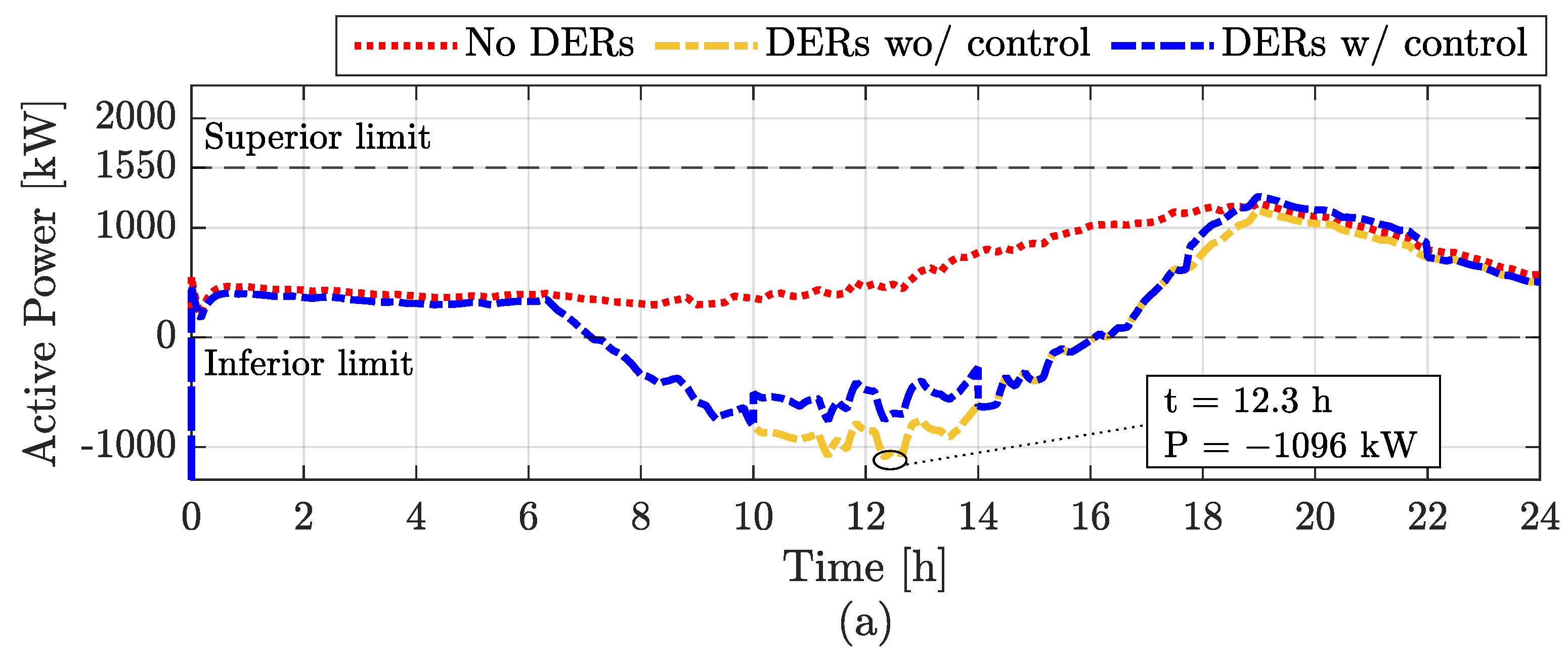
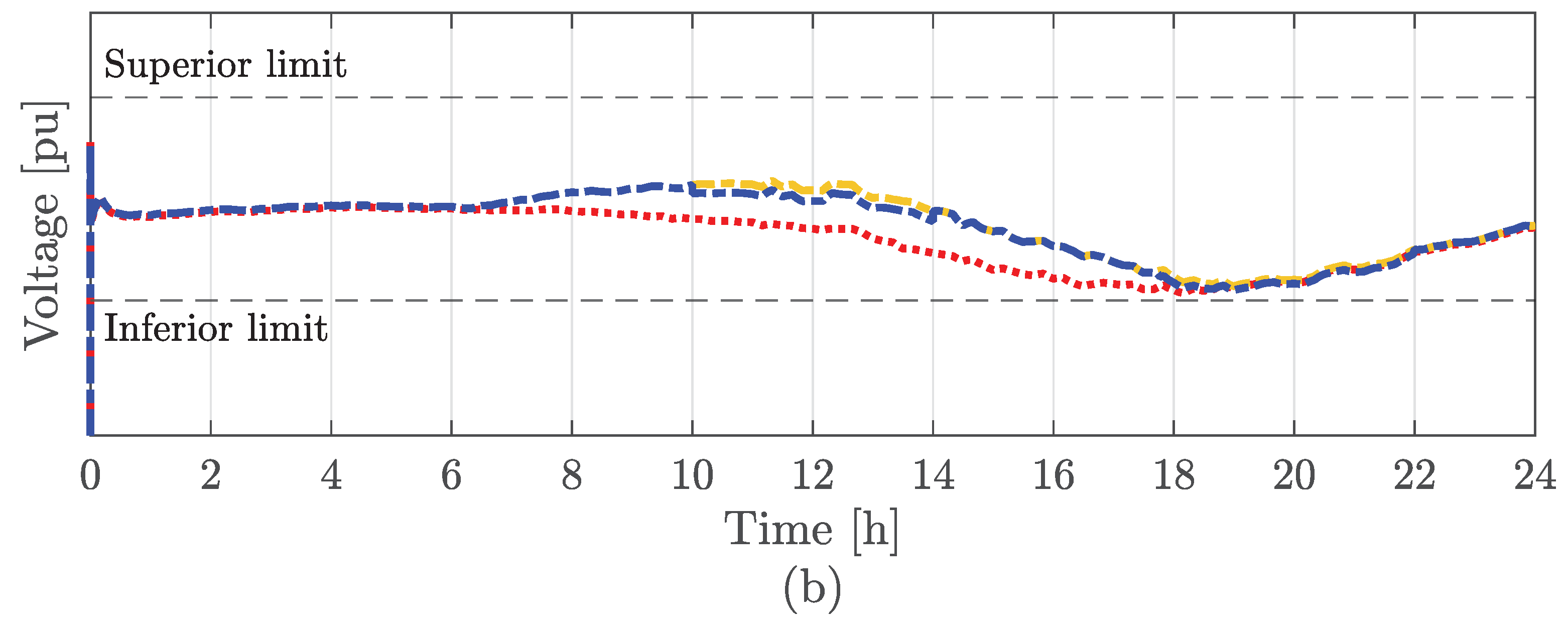
Figure 8 presents the power terms and collective RMS voltage of the PCC considering that there are no FCSs in the minigrid (scenarios 1 to 3 of Table 5). The positive power in PCC flows from the upstream grid to the minigrid and vice versa.
In the base scenario (scenario 1 of Table 5), there is no violation of the established limits. As it only has consumer loads, there is no active power dispatch from the minigrid to the upstream network. Furthermore, the minigrid loads are not sufficient to exceed the upper limit. In this way, the voltage in the PCC remains within the limits considered appropriate, not exceeding the lower voltage limit, as shown in Figure 8b.
However, when adding only non-dispatchable DERs (scenario 2 of Table 5), the lower power limit is exceeded, reaching 1096 kW of active power dispatch in the upstream grid. With microgrid control applied to dispatchable DERs (scenario 3 of Table 5), there is a power reduction, but not enough to maintain power above the lower level.
4.2. Scenarios with Uncontrolled FCS
Figure 9 shows the power terms and collective RMS voltage of the PCC considering that the MGCC does not control the FCS present in the minigrid (scenarios 4 to 6 of Table 5).
Analyzing the scenario without DERs (scenario 4 of Table 5) presented in Figure 9a, a violation of the upper power limit is observed from 2 p.m. onwards, ceasing only at 10 p.m. The PCC voltage is considered precarious according to Table 7. There is also a violation of the upper limit for cases with DERs without and with control between 6 p.m. and 10 p.m. With the increase in load caused by the FCS and most of the generation concentrated at times of low load, none of the scenarios evaluated allowed for load relief from 6 p.m. to 10 p.m.
Considering the scenario with uncontrolled DERs (scenario 5 of Table 5), there was a violation of the lower limit in the highest generation interval (between 10 a.m. and 2 p.m.) with a minimum of −344 kW. For the scenario with DERs with control (scenario 6 of Table 5), there was no violation of the lower limit. It is worth mentioning that scenario 6 of Table 5 is equivalent to the original PBC since there is control of the DERs, but there is no control of the FCS.
Compared to the scenarios presented in Figure 8, it was possible, by controlling the dispatchable DERs through PBC, to regulate the active power in PCC and not dispatch active power to the upstream grid at the time of highest generation. The consumption of FCSs was essential to absorb the excess power of non-dispatchable DERs. However, the power in the PCC reached a value of 28% above the upper limit, even with the maximum power dispatch of the DERs.
4.3. Scenarios with FCS with Control
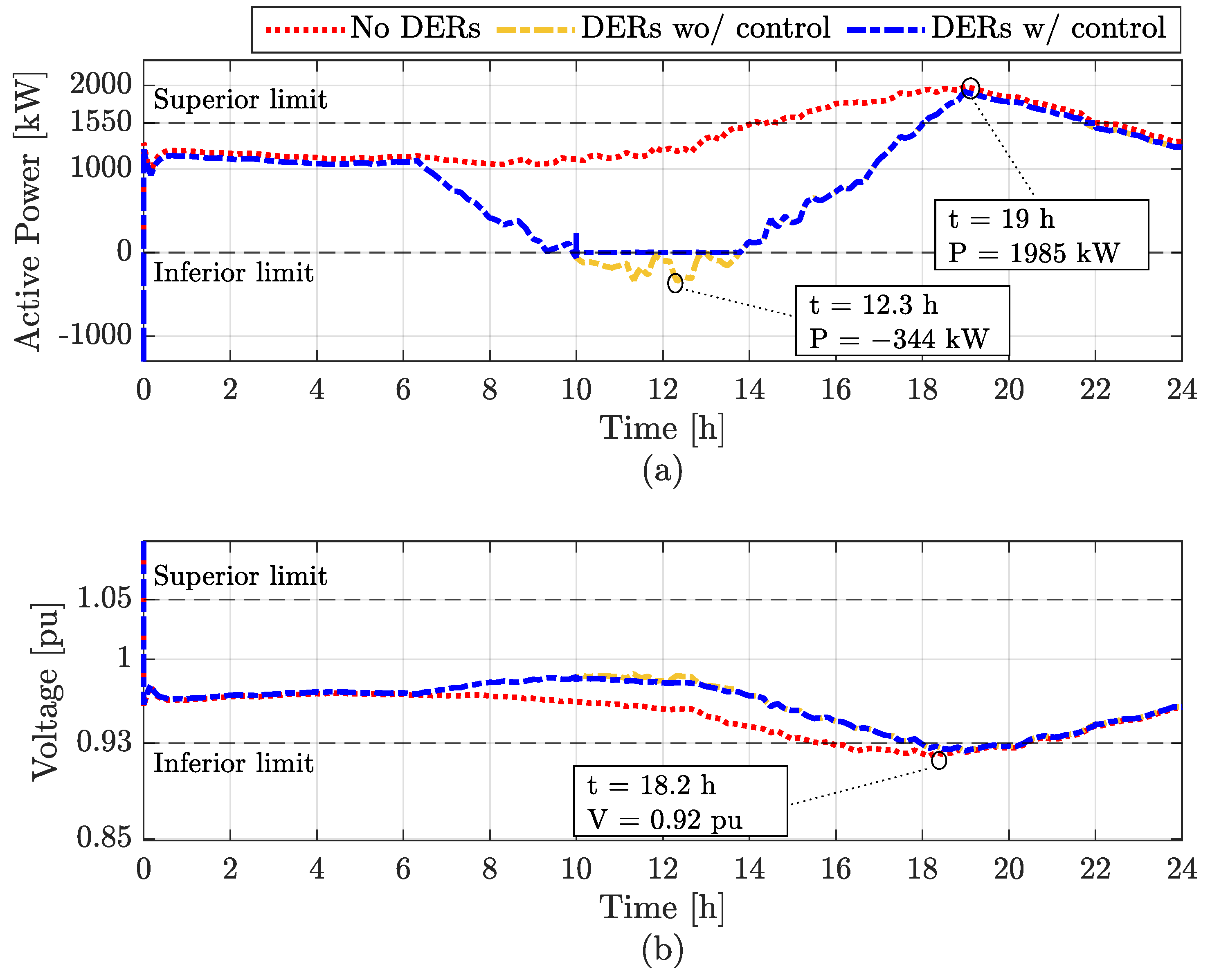
Figure 10 shows the power terms and collective RMS voltage of the PCC considering that the MGCC controls the FCS present in the microgrid (scenarios 7 to 9 from Table 5).
Analyzing the scenario without DERs (scenario 7 of Table 5) presented in Figure 10a, it is observed that there is a violation of the upper power limit from 2 p.m. onwards, as well as the scenario without DERs presented in Figure 9a. However, from 6 p.m. to 9 p.m., the power in the PCC remains below the upper limit of Table 6.
One of the solutions to not exceed the upper limit in this scenario would be to extend the microgrid control period between 2 p.m. and 10 p.m. However, this would require a lot of energy from the BESS present at the stations since they would operate 4 h longer with reduced grid demand. Figure 11 shows the coefficients for the three scenarios evaluated in Figure 10. It is possible to observe that the index is higher for the case without DERs, reaching a maximum of one. As stations reduce their demand according to the magnitude of , the case without DERs ceases the demand from the FCS, requiring the BESS to provide all the power necessary to recharge the vehicles.
In the scenario with uncontrolled DERs (scenario 8 of Table 5) presented in Figure 10a, there is no violation of the upper limit at any time throughout the day. Therefore, there is also no violation of the lower voltage limit in the PCC of the microgrid, which always remains within the limits considered appropriate according to Table 7. However, it was not possible to maintain the power in the PCC above the lower limit between 10 a.m. and 2 p.m.
Also, analyzing Figure 11, the coefficient remained at high negative values, peaking at −0.46. As a result, dispatchable DERs must absorb energy at 46% of their maximum capacity, and charging stations must increase their demand by 46%. Considering a maximum demand increase of 20% in an FCS, the charging station limits its energy absorption and, therefore, there will be deviations from the limit reference lower than the active power in the PCC of the minigrid.
In the scenario with DERs with control (scenario 9 of Table 5), there is no violation of the lower and upper limits, maintaining the voltage within the limits considered adequate according to Table 7. Confront the values of in Figure 11 of the scenarios with DERs without control and with control, and it is observed that the minimum value of is above −0.2 (−20%), which means that FCSs can increase their demand without exceeding the imposed limits. Furthermore, at some times during the interval from 10 a.m. to 2 p.m., the values become positive, which means that the FCSs reduce their active power demand while the DERs’ dispatchables begin to inject active power into the grid, even in a condition of high generation by non-dispatchable DERs.
Figure 10 (DERs with control) shows that only with the simultaneous control of the DERs and FCSs was it possible to maintain the PCC power between the lower and upper limits. In this way, the PCC voltage remained at appropriate values.
By controlling only the DERs, the control is not able to keep the power in the PCC below the upper limit, as shown in Figure 9 (DERs w/control). In this condition, the PCC power exceeded the upper limit by 28%, taking the voltage in the PCC to a precarious level. By controlling only the FCS, the control is not able to maintain the power in the PCC above the lower limit, as shown in Figure 10 (DERs wo/control). In this condition, the PCC power exceeded the lower limit by 254 kW, dispatching power to the upstream network.
5. Discussion of Results
Figure 8 presents the scenarios without FCSs. It shows that the insertion of DERs without energy storages or without sufficient load at times of high generation causes an increase in voltage levels, especially at the DERs’ connection points. Without controlling the DERs’ power dispatch, there is a high power dispatch from the minigrid to the upstream network, which causes an increase in voltage in the PCC. For the case studied, this value was 1 MW of power in a minigrid unprepared for reverse power flow. With the control of dispatchable DERs, this value is reduced but still significant for the reverse power flow.
Increased energy consumption reduces the possibility of overvoltage on the electric grid. However, unrestrained insertion without load control can cause feeders to overload at times of high demand. Figure 9 presents scenarios with increased energy consumption through FCSs. Due to the incompatibility between generation and demand, the overload of the electrical system caused by FCSs shows that increasing consumption without coordination is not enough to avoid energy-quality problems in the electrical grid. In this case study, the insertion of FCSs into the electrical grid without coordination caused an overload of 28% in the PCCs of the minigrid during periods of high energy demand.
Figure 10 shows that the insertion of FCSs without DERs substantially increases the overload periods. Figure 11 shows that, in the case study of this work, there is an excessive use of BESSs of FCSs in a grid without distributed generation. Inserting DERs alleviates periods of overload. However, controlling only the loads (FCSs) does not prevent the reverse power flow with the upstream electrical grid, violated at 344 kW for the case study. Only the control of the DERs simultaneously and coordinated with controllable loads such as the FCSs allows ancillary services such as valley filling to be carried out, avoiding reverse power flow and peak shaving and avoiding overload on the PCC of the minigrid.
6. Conclusions
The proposed method is suitable for the simultaneous coordinated control of fast charging stations (FCSs) and distributed energy resources (DERs). By controlling only the DERs of the minigrid, there is a violation of the upper power level in the minigrid (MG) point of common coupling (PCC), taking the voltage to precarious operating levels (below 0.93 pu). Controlling only the FCSs, there is a dispatch of 254 kW between the MG and the upstream electrical grid, undesirable in a zero-flow condition. With the proposed method, it is possible to guarantee the reliability of grid power quality parameters.
Low-voltage microgrids with controllable loads, such as lower-power vehicle chargers or builds with energy storage, can also operate with the proposed control. The algorithm is interesting in microgrids with high non-dispatchable generation, being able to increase the hosting capacity with the insertion of controllable loads in the system, such as charging stations equipped with energy storages, avoiding overvoltage levels in the hosting capacity PCC of this microgrid at times of high generation without impacting voltage levels at times of greater demand. The purpose of this work performs the ancillary services of valley filling and peak shaving, maintaining voltage and power levels within appropriate values and contributing to the simultaneous control studies of DERs and FCS. This type of control allows for greater operational flexibility for the distribution system operator. With this, large cities can operate with the addition of DERs and FCSs, avoiding changes to the network infrastructure, reducing costs for the system operator and consumers, and maintaining the safety and reliability of the electrical power system.
Author Contributions
Conceptualization, all authors; methodology, all authors; software, D.A.d.L.B. and D.I.B.; validation, D.A.d.L.B.; formal analysis, D.A.d.L.B.; investigation, D.A.d.L.B.; resources, I.A.P. and D.I.B.; data curation, D.A.d.L.B.; writing—original draft preparation, D.A.d.L.B.; writing—review and editing, all authors; visualization, all authors; supervision, I.A.P. and D.I.B.; project administration, I.A.P.; funding acquisition, I.A.P. All authors have read and agreed to the published version of the manuscript.
Funding
This research received no external funding.
Institutional Review Board Statement
Not applicable.
Informed Consent Statement
Not applicable.
Data Availability Statement
Data are contained within the article.
Acknowledgments
This work was carried out with the support of the Coordination for the Improvement of Higher Education Personnel—Brazil (CAPES) through the Academic Excellence Program (PROEX), in part by Conselho Nacional de Desenvolvimento Científico e Tecnológico (CNPq), and in part by the Minas Gerais state government agency Fundação de Amparo à Pesquisa do Estado de Minas Gerais (FAPEMIG).
Conflicts of Interest
The authors declare no conflicts of interest.
Abbreviations
| ANEEL | Agência Nacional de Energia Elétrica |
| BESS | battery energy storage system |
| DER | distributed energy resource |
| DSO | distribution system operator |
| EV | electric vehicle |
| FCS | fast charging station |
| FCSCC | fast charging station central controller |
| LV | low voltage |
| MG | minigrid |
| MGCC | minigrid central controller |
| MISO | multiple inputs single output |
| MV | medium voltage |
| PBC | power-based control |
| PCC | point of common coupling |
| PI | proportional-integral |
| PRODIST | Procedimento de Distribuição de Energia Elétrica no Sistema Elétrico Nacional |
| SoC | state of charge |
| G | microgrid |
| GCC | microgrid central controller |
| V2G | vehicle-to-grid |
References
- National Geographic. Air Pollution. 2023. Available online: https://education.nationalgeographic.org/resource/air-pollution/ (accessed on 12 January 2024).
- Air Quality Life Index (AQLI). South Korea Analysis: Air Pollution Cuts Lives Short by More than a Year. 2019. Available online: https://aqli.epic.uchicago.edu/news/south-korea-analysis-air-pollution-cuts-lives-short-by-more-than-a-year/ (accessed on 12 January 2024).
- United States Environmental Protection Agency (EPA). Summary of the Clean Air Act. 2023. Available online: https://www.epa.gov/laws-regulations/summary-clean-air-act (accessed on 13 January 2024).
- European Environment Agency. Emissions of the Main Air Pollutants in Europe. 2023. Available online: https://eea.europa.eu/en/analysis/indicators/emissions-of-the-main-air (accessed on 12 January 2024).
- United States Environmental Protection Agency (EPA). Carbon Pollution from Transportation. 2022. Available online: https://www.epa.gov/transportation-air-pollution-and-climate-change/carbon-pollution-transportation (accessed on 14 January 2024).
- The New York Times. For Electric Car Owners, ‘Range Anxiety’ Gives Way to ‘Charging Time Trauma’. 2017. Available online: https://www.nytimes.com/2017/10/05/automobiles/wheels/electric-cars-charging.html (accessed on 12 January 2024).
- U.S. News & World Report. 11 Reasons People Don’t Buy Electric Cars (and Why They’re Wrong). 2023. Available online: https://cars.usnews.com/cars-trucks/advice/why-people-dont-buy-electric-cars (accessed on 16 January 2024).
- Kantar. Understanding Consumer Attitudes Towards Electric Vehicles. 2023. Available online: https://www.kantar.com/inspiration/research-services/understanding-consumer-attitudes-towards-electric-vehicles-pf (accessed on 16 January 2024).
- Federal Highway Administration—U.S. Departament of Transportation. National Electric Vehicle Infrastructure Formula Program. 2022. Available online: https://www.fhwa.dot.gov/environment/alternative_fuel_corridors/resources/nprm_evcharging_unofficial.pdf (accessed on 17 January 2024).
- Alternative Fuels Data Center. Alternative Fueling Station Counts by State. 2024. Available online: https://afdc.energy.gov/stations/states (accessed on 17 January 2024).
- International Energy Agency (IEA). Trends in Charging Infrastructure. 2023. Available online: https://www.iea.org/reports/global-ev-outlook-2023/trends-in-charging-infrastructure (accessed on 17 January 2024).
- Statista. Estimated Number of Plug-In Electric Vehicles in Use in Selected Countries as of 2022. 2022. Available online: https://www.statista.com/statistics/244292/number-of-electric-vehicles-by-country/ (accessed on 17 January 2024).
- Nafi, I.M.; Tabassum, S.; Hassan, Q.R.; Abid, F. Effect of Electric Vehicle Fast Charging Station on Residential Distribution Network in Bangladesh. In Proceedings of the 2021 5th International Conference on Electrical Engineering and Information Communication Technology (ICEEICT), Dhaka, Bangladesh, 18–20 November 2021; pp. 1–5. [Google Scholar] [CrossRef]
- Alshareef, S.M. Voltage Sag Assessment, Detection, and Classification in Distribution Systems Embedded With Fast Charging Stations. IEEE Access 2023, 11, 89864–89880. [Google Scholar] [CrossRef]
- Tovilović, D.M.; Rajaković, N.L. The simultaneous impact of photovoltaic systems and plug-in electric vehicles on the daily load and voltage profiles and the harmonic voltage distortions in urban distribution systems. Renew. Energy 2015, 76, 454–464. [Google Scholar] [CrossRef]
- Lamedica, R.; Geri, A.; Gatta, F.M.; Sangiovanni, S.; Maccioni, M.; Ruvio, A. Integrating Electric Vehicles in Microgrids: Overview on Hosting Capacity and New Controls. IEEE Trans. Ind. Appl. 2019, 55, 7338–7346. [Google Scholar] [CrossRef]
- Caro, L.M.; Ramos, G.; Rauma, K.; Rodriguez, D.F.C.; Martinez, D.M.; Rehtanz, C. State of Charge Influence on the Harmonic Distortion From Electric Vehicle Charging. IEEE Trans. Ind. Appl. 2021, 57, 2077–2088. [Google Scholar] [CrossRef]
- Chudy, A.; Hołyszko, P.; Mazurek, P. Fast Charging of an Electric Bus Fleet and Its Impact on the Power Quality Based on On-Site Measurements. Energies 2022, 15, 5555. [Google Scholar] [CrossRef]
- Nguyen, H.T.; Hosani, K.A.; Al-Sumaiti, A.S.; Nguyen, T.H.; Jaafari, K.A.A.; Alsawalhi, J.Y.; El Moursi, M.S. Fast Harmonic Rejecting Control Design to Enable Active Support of Charging Stations to Micro-Grids Under Distortion. IEEE Trans. Transp. Electrif. 2023, 9, 4132–4146. [Google Scholar] [CrossRef]
- Steen, D.; Tuan, L.A.; Carlson, O.; Bertling, L. Assessment of Electric Vehicle Charging Scenarios Based on Demographical Data. IEEE Trans. Smart Grid 2012, 3, 1457–1468. [Google Scholar] [CrossRef]
- Awadallah, M.A.; Singh, B.N.; Venkatesh, B. Impact of EV Charger Load on Distribution Network Capacity: A Case Study in Toronto. Can. J. Electr. Comput. Eng. 2016, 39, 268–273. [Google Scholar] [CrossRef]
- Ramadan, H.; Ali, A.; Farkas, C. Assessment of plug-in electric vehicles charging impacts on residential low voltage distribution grid in Hungary. In Proceedings of the 2018 6th International Istanbul Smart Grids and Cities Congress and Fair (ICSG), Istanbul, Turkey, 25–26 April 2018; pp. 105–109. [Google Scholar] [CrossRef]
- Coban, H.H.; Lewicki, W.; Sendek-Matysiak, E.; Łosiewicz, Z.; Drożdż, W.; Miśkiewicz, R. Electric Vehicles and Vehicle–Grid Interaction in the Turkish Electricity System. Energies 2022, 15, 8218. [Google Scholar] [CrossRef]
- European Council—Council of the European Union. Climate Change Summit COP26. 2021. Available online: https://www.consilium.europa.eu/en/policies/climate-change/paris-agreement/cop26/ (accessed on 21 January 2024).
- U.S. Department of Energy. Homeowner’s Guide to the Federal Tax Credit for Solar Photovoltaics. 2023. Available online: https://www.energy.gov/eere/solar/homeowners-guide-federal-tax-credit-solar-photovoltaics (accessed on 21 January 2024).
- Ministério do Desenvolvimento, Indústria, Comércio e Serviços—Brasil. Decreto do Governo Garante Isenção Fiscal Para Semicondutores e Inclui Energia Solar em Benefício. 2023. Available online: https://gov.br/mdic/pt-br/assuntos/noticias/2023/marco/decreto-do-governo-garante-isencao-fiscal-para-semicondutores-e-inclui-energia-solar-em-beneficio (accessed on 21 January 2024).
- Reuters. China Sets 2022 Renewable Power Subsidy at $607 mln. 2021. Available online: https://www.reuters.com/business/energy/china-sets-2022-renewable-power-subsidy-607-mln-2021-11-16/ (accessed on 21 January 2024).
- European Comission. EU Renewable Energy Financing Mechanism. 2023. Available online: https://energy.ec.europa.eu/topics/renewable-energy/financing/eu-renewable-energy-financing-mechanism_en (accessed on 21 January 2024).
- Hossain, E.; Tür, M.R.; Padmanaban, S.; Ay, S.; Khan, I. Analysis and Mitigation of Power Quality Issues in Distributed Generation Systems Using Custom Power Devices. IEEE Access 2018, 6, 16816–16833. [Google Scholar] [CrossRef]
- Zenhom, Z.M.; Aleem, S.H.E.A.; Zobaa, A.F.; Boghdady, T.A. A Comprehensive Review of Renewables and Electric Vehicles Hosting Capacity in Active Distribution Networks. IEEE Access 2024, 12, 3672–3699. [Google Scholar] [CrossRef]
- Falahi, M.; Chou, H.M.; Ehsani, M.; Xie, L.; Butler-Purry, K.L. Potential Power Quality Benefits of Electric Vehicles. IEEE Trans. Sustain. Energy 2013, 4, 1016–1023. [Google Scholar] [CrossRef]
- Pahasa, J.; Ngamroo, I. PHEVs Bidirectional Charging/Discharging and SoC Control for Microgrid Frequency Stabilization Using Multiple MPC. IEEE Trans. Smart Grid 2015, 6, 526–533. [Google Scholar] [CrossRef]
- Bayat, M.; Sheshyekani, K.; Rezazadeh, A. A Unified Framework for Participation of Responsive End-User Devices in Voltage and Frequency Control of the Smart Grid. IEEE Trans. Power Syst. 2015, 30, 1369–1379. [Google Scholar] [CrossRef]
- Weckx, S.; Driesen, J. Load Balancing with EV Chargers and PV Inverters in Unbalanced Distribution Grids. IEEE Trans. Sustain. Energy 2015, 6, 635–643. [Google Scholar] [CrossRef]
- Akhavan-Rezai, E.; Shaaban, M.F.; El-Saadany, E.F.; Karray, F. Managing Demand for Plug-in Electric Vehicles in Unbalanced LV Systems With Photovoltaics. IEEE Trans. Ind. Inform. 2017, 13, 1057–1067. [Google Scholar] [CrossRef]
- Rana, R.; Singh, M.; Mishra, S. Design of Modified Droop Controller for Frequency Support in Microgrid Using Fleet of Electric Vehicles. IEEE Trans. Power Syst. 2017, 32, 3627–3636. [Google Scholar] [CrossRef]
- Datta, U.; Kalam, A.; Shi, J.; Li, J. Electric Vehicle Charging Station for Providing Primary Frequency Control in Microgrid. In Proceedings of the 2019 14th IEEE Conference on Industrial Electronics and Applications (ICIEA), Xi’an, China, 19–21 June 2019; pp. 2440–2444. [Google Scholar] [CrossRef]
- Ahmad, F. Analysis of Microgrids for Plug-in Hybrid Electric Vehicles Charging Stations. Ph.D. Thesis, Department of Electrical Engineering, Faculty of Engineering & Technology, Aligarh Muslim University, Aligarh, India, 2019. [Google Scholar]
- Rücker, F.; Merten, M.; Gong, J.; Villafáfila-Robles, R.; Schoeneberger, I.; Sauer, D.U. Evaluation of the Effects of Smart Charging Strategies and Frequency Restoration Reserves Market Participation of an Electric Vehicle. Energies 2020, 13, 3112. [Google Scholar] [CrossRef]
- Da Silva, E.C.; Melgar-Dominguez, O.D.; Romero, R. Simultaneous Distributed Generation and Electric Vehicles Hosting Capacity Assessment in Electric Distribution Systems. IEEE Access 2021, 9, 110927–110939. [Google Scholar] [CrossRef]
- Lai, C.S.; Chen, D.; Xu, X.; Taylor, G.A.; Pisica, I.; Lai, L.L. Operational Challenges to Accommodate High Penetration of Electric Vehicles: A Comparison between UK and China. In Proceedings of the 2021 IEEE 15th International Conference on Compatibility, Power Electronics and Power Engineering (CPE-POWERENG), Florence, Italy, 14–16 July 2021; pp. 1–7. [Google Scholar] [CrossRef]
- Kasturi, K.; Nayak, C.; Nayak, M. Photovoltaic and Electric Vehicle-to-Grid Strategies for Peak Load Shifting in Low Voltage Distribution System Under Time of Use Grid Pricing. Iran. J. Sci. Technol. Trans. Electr. Eng. 2021, 45, 789–801. [Google Scholar] [CrossRef]
- Khazali, A.; Rezaei, N.; Saboori, H.; Guerrero, J.M. Using PV systems and parking lots to provide virtual inertia and frequency regulation provision in low inertia grids. Electr. Power Syst. Res. 2022, 207, 107859. [Google Scholar] [CrossRef]
- Kiani, S.; Sheshyekani, K.; Dagdougui, H. An Extended State Space Model for Aggregation of Large-Scale EVs Considering Fast Charging. IEEE Trans. Transp. Electrif. 2023, 9, 1238–1251. [Google Scholar] [CrossRef]
- Morstyn, T.; Hredzak, B.; Agelidis, V.G. Control Strategies for Microgrids With Distributed Energy Storage Systems: An Overview. IEEE Trans. Smart Grid 2018, 9, 3652–3666. [Google Scholar] [CrossRef]
- Gao, X.; De Carne, G.; Andresen, M.; Brüske, S.; Pugliese, S.; Liserre, M. Voltage-Dependent Load-Leveling Approach by Means of Electric Vehicle Fast Charging Stations. IEEE Trans. Transp. Electrif. 2021, 7, 1099–1111. [Google Scholar] [CrossRef]
- Zahedmanesh, A.; Muttaqi, K.M.; Sutanto, D. Active and Reactive Power Control of PEV Fast Charging Stations Using a Consecutive Horizon-Based Energy Management Process. IEEE Trans. Ind. Inform. 2021, 17, 6742–6753. [Google Scholar] [CrossRef]
- Radu, A.T.; Eremia, M.; Toma, L. Use of Battery Storage Systems in EV Ultrafast Charging Stations for Load Spikes Mitigation. Sci. Bull.-Univ. Politeh. Buchar. 2021, 83, 283–294. [Google Scholar]
- Gao, X.; De Carne, G.; Langwasser, M.; Liserre, M. Online Load Control in Medium Voltage Grid by Means of Reactive Power Modification of Fast Charging Station. In Proceedings of the 2019 IEEE Milan PowerTech, Milan, Italy, 23–27 June 2019; pp. 1–6. [Google Scholar] [CrossRef]
- Gjelaj, M.; Hashemi, S.; Traeholt, C.; Andersen, P.B. Grid integration of DC fast-charging stations for EVs by using modular li-ion batteries. IET Gener. Transm. Distrib. 2018, 12, 4368–4376. [Google Scholar] [CrossRef]
- Yang, H.; Pan, H.; Luo, F.; Qiu, J.; Deng, Y.; Lai, M.; Dong, Z.Y. Operational Planning of Electric Vehicles for Balancing Wind Power and Load Fluctuations in a Microgrid. IEEE Trans. Sustain. Energy 2017, 8, 592–604. [Google Scholar] [CrossRef]
- Cheng, Q.; Chen, L.; Sun, Q.; Wang, R.; Ma, D.; Qin, D. A smart charging algorithm based on a fast charging station without energy storage system. CSEE J. Power Energy Syst. 2021, 7, 850–861. [Google Scholar] [CrossRef]
- Lymperopoulos, I.; Qureshi, F.A.; Bitlislioglu, A.; Poland, J.; Zanarini, A.; Mercangoez, M.; Jones, C. Ancillary Services Provision Utilizing a Network of Fast-Charging Stations for Electrical Buses. IEEE Trans. Smart Grid 2020, 11, 665–672. [Google Scholar] [CrossRef]
- Yong, J.Y.; Ramachandaramurthy, V.K.; Tan, K.M.; Mithulananthan, N. Bi-directional electric vehicle fast charging station with novel reactive power compensation for voltage regulation. Int. J. Electr. Power Energy Syst. 2015, 64, 300–310. [Google Scholar] [CrossRef]
- Yuan, H.; Wei, G.; Zhu, L.; Zhang, X.; Zhang, H.; Luo, Z.; Hu, J. Optimal scheduling for micro-grid considering EV charging–swapping–storage integrated station. IET Gener. Transm. Distrib. 2020, 14, 1127–1137. [Google Scholar] [CrossRef]
- Liu, Y.; Wang, Y.; Li, Y.; Gooi, H.B.; Xin, H. Multi-Agent Based Optimal Scheduling and Trading for Multi-Microgrids Integrated With Urban Transportation Networks. IEEE Trans. Power Syst. 2021, 36, 2197–2210. [Google Scholar] [CrossRef]
- Ton, D.; Reilly, J. Microgrid Controller Initiatives: An Overview of R&D by the U.S. Department of Energy. IEEE Power Energy Mag. 2017, 15, 24–31. [Google Scholar] [CrossRef]
- Caldognetto, T.; Buso, S.; Tenti, P.; Brandao, D.I. Power-Based Control of Low-Voltage Microgrids. IEEE J. Emerg. Sel. Top. Power Electron. 2015, 3, 1056–1066. [Google Scholar] [CrossRef]
- Brandao, D.I.; Caldognetto, T.; Marafão, F.P.; Simões, M.G.; Pomilio, J.A.; Tenti, P. Centralized Control of Distributed Single-Phase Inverters Arbitrarily Connected to Three-Phase Four-Wire Microgrids. IEEE Trans. Smart Grid 2017, 8, 437–446. [Google Scholar] [CrossRef]
- Brandao, D.I.; de Araújo, L.S.; Caldognetto, T.; Pomilio, J.A. Coordinated control of three- and single-phase inverters coexisting in low-voltage microgrids. Appl. Energy 2018, 228, 2050–2060. [Google Scholar] [CrossRef]
- Araujo, L.S.; Brandao, D.I.; Silva, S.M.; Cardoso Filho, B.J. Reactive Power Support in Medium Voltage Networks by Coordinated Control of Distributed Generators in Dispatchable Low-Voltage Microgrid. In Proceedings of the 2019 IEEE 28th International Symposium on Industrial Electronics (ISIE), Vancouver, BC, Canada, 12–14 June 2019; pp. 2603–2608. [Google Scholar] [CrossRef]
- Brandao, D.I.; Araujo, L.S.; Alonso, A.M.S.; dos Reis, G.L.; Liberado, E.V.; Marafão, F.P. Coordinated Control of Distributed Three- and Single-Phase Inverters Connected to Three-Phase Three-Wire Microgrids. IEEE J. Emerg. Sel. Top. Power Electron. 2020, 8, 3861–3877. [Google Scholar] [CrossRef]
- Brandao, D.I.; Santos, R.P.d.; Silva, W.W.A.G.; Oliveira, T.R.; Donoso-Garcia, P.F. Model-Free Energy Management System for Hybrid Alternating Current/Direct Current Microgrids. IEEE Trans. Ind. Electron. 2021, 68, 3982–3991. [Google Scholar] [CrossRef]
- Ferreira, D.M.; Brandao, D.I.; Bergna-Diaz, G.; Tedeschi, E.; Silva, S.M. Distributed Control Strategy for Low-Voltage Three-Phase Four-Wire Microgrids: Consensus Power-Based Control. IEEE Trans. Smart Grid 2021, 12, 3215–3231. [Google Scholar] [CrossRef]
- Dos Reis, G.; Liberado, E.; Marafão, F.; Sousa, C.; Silva, W.; Brandao, D. Model-Free Power Control for Low-Voltage AC Dispatchable Microgrids with Multiple Points of Connection. Energies 2021, 14, 6390. [Google Scholar] [CrossRef]
- Reis, G.L.; Brandao, D.I.; Oliveira, J.H.; Araujo, L.S.; Cardoso Filho, B.J. Case Study of Single-Controllable Microgrid: A Practical Implementation. Energies 2022, 15, 6400. [Google Scholar] [CrossRef]
- Callegari, J.M.S.; Pereira, H.A.; Brandao, D.I. Voltage Support and Selective Harmonic Current Compensation in Advanced AC Microgrids. IEEE Trans. Ind. Appl. 2023, 59, 4880–4892. [Google Scholar] [CrossRef]
- Soares Callegari, J.M.; Araujo, L.S.; De Lisboa Brandão, D.A.; Cardoso Filho, B.J.; Brandao, D.I. Centralized Strategy Incorporating Multiple Control Actions Applied to Advanced Microgrids. In Proceedings of the 2023 IEEE 8th Southern Power Electronics Conference (SPEC), Florianopolis, Brazil, 26–29 November 2023; pp. 1–7. [Google Scholar] [CrossRef]
- Federal Communications Commission. FCC Finds U.S. Broadband Deployment Not Keeping Pace. 2015. Available online: https://www.fcc.gov/document/fcc-finds-us-broadband-deployment-not-keeping-pace-0 (accessed on 22 January 2024).
- Ramos, G.V.; Parreiras, T.M.; Brandão, D.A.d.L.; Silva, S.M.; Filho, B.d.J.C. A Zero Harmonic Distortion Grid-Forming Converter for Islanded Microgrids. In Proceedings of the 2023 IEEE Industry Applications Society Annual Meeting (IAS), Nashville, TN, USA, 29 October–2 November 2023; pp. 1–8. [Google Scholar] [CrossRef]
- Brandao, D.A.L.; Parreiras, T.M.; Callegari, J.M.S.; Pires, I.A.; Brandao, D.I.; Cardoso Filho, B.D.J. Power-based Control for Microgrids and Extreme Fast Charging Stations with Low-Harmonic Current Content in the Medium Voltage Power Grid. In Proceedings of the 2023 IEEE Transportation Electrification Conference & Expo (ITEC), Detroit, MI, USA, 21–23 June 2023; pp. 1–6. [Google Scholar] [CrossRef]
- TeslaTap. Supercharger Superguide. 2023. Available online: https://teslatap.com/articles/supercharger-superguide/ (accessed on 21 October 2023).
- Induscabos—Condutores Elétricos. Electrical Parameters—Medium Voltage Cables. 2018. Available online: https://www.induscabos.com.br/wp-content/uploads/2018/03/induscabos-parametros-eletricos-cabos-de-media-tensao.pdf (accessed on 21 October 2023).
- Pedrotti, R.F. Simulação Termo Energética de um Supermercado. Master’s Thesis, Energy Engineering, Universidade Federal do Rio Grande do Sul, Porto Alegre, Brazil, 2015. [Google Scholar]
- Origin. Origin1500 1.5kW Solar System Panel Specifications. 2023. Available online: https://www.originenergy.com.au/wp-content/uploads/Origin1500B_Solar_Panel_Brochure.pdf (accessed on 21 October 2023).
- Newaz, A.; Ospina, J.; Faruque, M.O. Controller Hardware-in-the-Loop Validation of a Graph Search Based Energy Management Strategy for Grid-Connected Distributed Energy Resources. IEEE Trans. Energy Convers. 2020, 35, 520–528. [Google Scholar] [CrossRef]
- Rafique, S.; Hossain, M.J.; Nizami, M.S.H.; Irshad, U.B.; Mukhopadhyay, S.C. Energy Management Systems for Residential Buildings With Electric Vehicles and Distributed Energy Resources. IEEE Access 2021, 9, 46997–47007. [Google Scholar] [CrossRef]
- Ahmad, S.; Shafiullah, M.; Ahmed, C.B.; Alowaifeer, M. A Review of Microgrid Energy Management and Control Strategies. IEEE Access 2023, 11, 21729–21757. [Google Scholar] [CrossRef]
- Agência Nacional de Energia Elétrica. Procedimentos de Distribuição de Energia Elétrica No Sistema Elétrico Nacional—PRODIST—Módulo 8—Qualidade do Fornecimento de Energia Elétrica. 2021. Available online: https://www2.aneel.gov.br/cedoc/aren2021956_2_7.pdf (accessed on 24 October 2023).
Figure 1.
Representation of the medium-voltage minigrid to validate the proposal.

Figure 5.
Algorithm of the proposed minigrid control system.

Figure 6.
Power profiles: (a) dispatchable DERs. (b) non-dispatchable DERs. (c) load. (d) dispatchable DERs. (e) non-dispatchable DERs. (f) load.
Figure 6.
Power profiles: (a) dispatchable DERs. (b) non-dispatchable DERs. (c) load. (d) dispatchable DERs. (e) non-dispatchable DERs. (f) load.

Figure 7.
Power profiles: (a) dispatchable DERs. (b) non-dispatchable DERs. (c) load. (d) Internal and (e) external load of the minigrid and (f) internal generator.
Figure 7.
Power profiles: (a) dispatchable DERs. (b) non-dispatchable DERs. (c) load. (d) Internal and (e) external load of the minigrid and (f) internal generator.

Figure 8.
(a,b) Power and RMS voltage in the PCC of the microgrid considering the absence of FCS in three situations: without DERs (scenario 1), all DERs are non-dispatchable (scenario 2), and DERs dispatchable and not dispatchable (scenario 3).
Figure 8.
(a,b) Power and RMS voltage in the PCC of the microgrid considering the absence of FCS in three situations: without DERs (scenario 1), all DERs are non-dispatchable (scenario 2), and DERs dispatchable and not dispatchable (scenario 3).


Figure 9.
(a,b) Power and RMS voltage in the PCC of the microgrid with non-controllable FCS in three situations: without DERs (scenario 4), all DERs are non-dispatchable (scenario 5), and DERs are dispatchable and not dispatchable (scenario 6).
Figure 9.
(a,b) Power and RMS voltage in the PCC of the microgrid with non-controllable FCS in three situations: without DERs (scenario 4), all DERs are non-dispatchable (scenario 5), and DERs are dispatchable and not dispatchable (scenario 6).

Figure 10.
(a,b) Power and RMS voltage at PCC of the minigrid with FCS controllable in three situations: without DERs (scenario 7), all DERs are non-dispatchable (scenario 8), and DERs are dispatchable and not dispatchable (scenario 9).
Figure 10.
(a,b) Power and RMS voltage at PCC of the minigrid with FCS controllable in three situations: without DERs (scenario 7), all DERs are non-dispatchable (scenario 8), and DERs are dispatchable and not dispatchable (scenario 9).

Figure 11.
Coefficient values with FCS controllable in three situations: without DERs, all DERs are non-dispatchable, and DERs are dispatchable and not dispatchable.
Figure 11.
Coefficient values with FCS controllable in three situations: without DERs, all DERs are non-dispatchable, and DERs are dispatchable and not dispatchable.


Table 1.
Proposals that use FCS to provide ancillary services.
| Reference | Voltage Level | Ancillary Service Category | DERs Control | FCSs Control | Control Architecture a |
|---|---|---|---|---|---|
| [18] | low voltage (LV) | Power quality (voltage and frequency disturbances and harmonic injection) | ✗ | ✗ | ✗/✗ |
| [14] | medium voltage (MV) | Power quality (transient voltage disturbances) | ✗ | ✗ | ✗/✗ |
| [46] | MV | Reactive power support (voltage control) | ✗ | ✓ | ✗/C |
| [13] | MV | Power quality (voltage disturbances) | ✗ | ✗ | ✗/✗ |
| [47] | MV | Active/reactive power support (voltage control) | ✗ | ✓ | ✗/C |
| [48] | LV | Active power support (peak shaving) | ✗ | ✓ | ✗/D |
| [49] | MV | Reactive power support (voltage support) | ✗ | ✓ | ✗/D |
| [50] | MV | - | ✗ | ✓ | ✗/D |
| [51] | MV | Active power support (peak shaving) | ✗ | ✓ | ✗/C |
| [52] | LV | - | ✗ | ✓ | ✗/C |
| [53] | MV | Active power support (load shifting) | ✗ | ✓ | ✗/D |
| [54] | MV | Reactive power support (voltage support) | ✗ | ✓ | ✗/D |
| [55] | MV | Active power support (load shifting) | ✗ | ✓ | ✗/C |
| [56] | MV | - | ✓ | ✗ | C/✗ |
| Here | LV/MV | Active power support: peak shaving and valley filling | ✓ | ✓ | C/C |
a D = decentralized and C = centralized.
Table 2.
PBC enhancements and applications.
| Reference | Microgrid Configuration | Migrogrid Control Architecture | Power Quality Compensation | Active Load Control | Sharing Coefficients |
|---|---|---|---|---|---|
| [58] | 1 to 2 wires and low voltage | Centralized | Reactive and load unbalance | ✗ | e |
| [59] | 1 and 3 to 4 wires and low voltage | Centralized | Reactive and load balance | ✗ | , , , , e |
| [60] | 1 and 3 to 4 wires and low voltage | Centralized | Reactive and load balance | ✗ | , , , , , , e |
| [61] | 1 and 3 to 4 wires and low voltage | Centralized | Reactive and load balance | ✗ | , , , , e |
| [62] | 1 and 3 to 4 wires and low voltage | Centralized | Reactive and load balance | ✗ | , , , , , , e |
| [63] | 1 to 2 wire and low voltage | Centralized | Reactive and load unbalance | ✗ | , , , , e |
| [64] | 1 and 3 to 4 wires and low voltage | Distributed | Load balance | ✗ | , , e |
| [65] | 1 and 2 to 4 wires and low voltage | Centralized | Reactive and load balance | ✗ | , , , , e |
| [66] | 1 and 2 to 4 wires and low voltage | Centralized | Reactive and load balance | ✗ | , , , , e |
| [67] | 1 and 3 to 4 wires and low voltage | Centralized/ decentralized | Reactive and load balance | ✗ | , , , , e |
| Here | 3 to 3 wires and medium voltage | Centralized | Load balance | ✓ |
Table 3.
Characteristics of the validation grid elements.
| Grid Element | Internal Elements | Load Profile | Power |
|---|---|---|---|
| LV Microgrid 1 | Non-dispatchable DERs | - | 80 kWp |
| Dispatchable DERs | - | 80 kWp | |
| Load | Residential | 200 kWp | |
| LV Microgrid 2 | Non-dispatchable DERs | - | 900 kWp |
| Dispatchable DERs | - | 60 kWp | |
| Load | Commercial | 450 kWp | |
| LV Microgrid 3 | Non-dispatchable DERs | - | 500 kWp |
| Dispatchable DERs | - | 80 kWp | |
| Load | Residential | 100 kWp | |
| FCS 1 | Chargers | - | 250 kW (3) |
| BESS | - | 750 kW | |
| BESS Energy | - | 646.4 kWh | |
| BESS state of charge (SoC) | - | 20% to 100% | |
| Contracted demand | - | 375 kW | |
| FCS 2 | Chargers | - | 250 kW (3) |
| BESS Power | - | 750 kW | |
| BESS Energy | - | 646.4 kWh | |
| BESS SoC | - | 20% to 100% | |
| Contracted demand | - | 375 kW | |
| Internal load | - | Residential | 670 kWp |
| External load | - | Residential | 4100 kWp |
| Internal generator | - | - | 370 kWp |
Table 4.
Equivalent resistances and inductances of the simulated grid cables.
| Symbol | Cable Cross-Section () a | Cable Length (km) | Equivalent Resistance () | Equivalent Inductance (mH) |
|---|---|---|---|---|
| 50 | 2.3 | 2.0 | 1.4 | |
| 50 | 1.7 | 1.2 | 0.9 | |
| 50 | 1.8 | 1.3 | 0.9 | |
| 50 | 1.5 | 1.0 | 0.7 | |
| 50 | 2.0 | 1.6 | 1.2 |
a Considering unipolar aluminum cables for voltages between 8.7 and 15 kV [73].
Table 5.
Possible scenarios for the operation of minigrid elements.
| Scenario | FCS? | DERs? | FCS Control? | DERs Control? |
|---|---|---|---|---|
| 1 | ✗ | ✗ | ✗ | ✗ |
| 2 | ✗ | ✓ | ✗ | ✗ |
| 3 | ✗ | ✓ | ✗ | ✓ |
| 4 | ✓ | ✗ | ✗ | ✗ |
| 5 | ✓ | ✓ | ✗ | ✗ |
| 6 | ✓ | ✓ | ✗ | ✓ |
| 7 | ✓ | ✗ | ✓ | ✗ |
| 8 | ✓ | ✓ | ✓ | ✗ |
| 9 | ✓ | ✓ | ✓ | ✓ |
Table 6.
Microgrid control activation periods and respective reference powers.
| Activation Periods | Reference Powers (kW) |
|---|---|
| 10 h to 14 h | 0 |
| 18 h to 22 h | 1550 |
Table 7.
Permanent voltage classification range for connection points with nominal voltage equal to or greater than 2.3 kV and less than 69 kV according to PRODIST.
Table 7.
Permanent voltage classification range for connection points with nominal voltage equal to or greater than 2.3 kV and less than 69 kV according to PRODIST.
| Service Voltage | Reading Voltage Variation Range (RV) in Relation to Reference Voltage (RefV) |
|---|---|
| Proper | |
| Precarious | |
| Critical | or |
Disclaimer/Publisher’s Note: The statements, opinions and data contained in all publications are solely those of the individual author(s) and contributor(s) and not of MDPI and/or the editor(s). MDPI and/or the editor(s) disclaim responsibility for any injury to people or property resulting from any ideas, methods, instructions or products referred to in the content. |
© 2024 by the authors. Licensee MDPI, Basel, Switzerland. This article is an open access article distributed under the terms and conditions of the Creative Commons Attribution (CC BY) license (https://creativecommons.org/licenses/by/4.0/).
Share and Cite
MDPI and ACS Style
Brandao, D.A.d.L.; Callegari, J.M.S.; Brandao, D.I.; Pires, I.A. Coordinated, Centralized, and Simultaneous Control of Fast Charging Stations and Distributed Energy Resources. Inventions 2024, 9, 35. https://doi.org/10.3390/inventions9020035
AMA Style
Brandao DAdL, Callegari JMS, Brandao DI, Pires IA. Coordinated, Centralized, and Simultaneous Control of Fast Charging Stations and Distributed Energy Resources. Inventions. 2024; 9(2):35. https://doi.org/10.3390/inventions9020035
Chicago/Turabian StyleBrandao, Dener A. de L., João M. S. Callegari, Danilo I. Brandao, and Igor A. Pires. 2024. "Coordinated, Centralized, and Simultaneous Control of Fast Charging Stations and Distributed Energy Resources" Inventions 9, no. 2: 35. https://doi.org/10.3390/inventions9020035