
An SIC-Fed Low-Profile Wideband Metamaterial-Based Antenna Array for 5G Wireless Cellular Networks


1
School of Information Science and Technology, University of Science and Technology of China, Hefei 230027, China
2
School of Advanced Manufacturing Engineering, Hefei University, Hefei 230601, China
*
Authors to whom correspondence should be addressed.
Designs 2022, 6(3), 43; https://doi.org/10.3390/designs6030043
Submission received: 7 April 2022
/
Revised: 28 April 2022
/
Accepted: 3 May 2022
/
Published: 9 May 2022
(This article belongs to the Section Electrical Engineering Design)
Abstract
:In this paper, we propose a metamaterial (MTM)-based low-profile wideband antenna and its array using a substrate integrated cavity (SIC) feed structure for 5G wireless cellular networks. The proposed wideband antenna consists of two sets of square mushroom-like arrays; a semi-ground plane and a microstrip line-fed bow-tie radiator. Due to the unique in-phase reflection characteristic of the mushroom-like metamaterial, the bow-tie antenna wideband performance is maintained while the distance between the bow-tie radiator and the metamaterial-based semi-ground is considerably reduced to 0.014λ0 (λ0 is the operating wavelength at 5 GHz in free space), thereby satisfying the compact size requirement desirable in many wireless communication systems. The in-phase reflection of the mushroom unit cell is applied to analyze and explain the wideband performance of the presented antenna. The proposed dielectric-filled () MTM-based wideband antenna element has an overall size of 1.0λ0 × 0.8λ0 × 0.054λ0 and attains a measured () bandwidth of 31.3%. Subsequently, an SIC feed structure is employed to form an array antenna, and a measured () bandwidth of about 17% is obtained. Across the operating bandwidth, which partly covers the 5G wireless communication in the sub-6 GHz band and 5-GHz WLAN, the antenna array achieved an average gain of 6.6 dBi and a radiation efficiency greater than 73%.
1. Introduction
With the rapid growth of wireless communications, broadband planar antennas are in great demand for use in various wireless communication systems. Microstrip antennas have played an important role in wireless communication systems over the past several decades due to their attractive features, such as being low-profile, light weight, low-cost and having easy integration with other microwave circuits. However, conventional microstrip antennas suffer from the inherent narrow impedance bandwidth (IBW), and a variety of techniques have been developed to increase the IBW, namely, the use of a thick substrate with a low-dielectric constant for lowering the quality factor (Q-factor) [1,2,3]. However, a thick substrate could increase losses due to the excitation of undesired surface waves, which lower not only the radiation efficiency, but also decrease the usable operating bandwidth [4]. The thick substrate also suffers from high cross-polarization at a higher band edge, especially in the H-plane. The slot-loading technique is usually introduced to further lower the quality factor of thick patch antennas, as the latter introduces a capacitance that compensates for the relatively high inductance of the lengthy feeding probe. By combining both the slot-loading and thick, low-dielectric-constant techniques, the IBW of the traditional patches can be enhanced to about 30% [5,6,7]. Moreover, electromagnetic coupling feed techniques, such as an L-probe and T-shaped probe are able to achieve bandwidths of 24% and 36%, respectively [8,9]. Stacking multiple patches is another effective way for enlarging the IBW of the patch [10]. However, for all the methods mentioned above, a thick (>0.1λ0, λ0 is the operating wavelength in free space), low-dielectric-constant substrate is required, which is undesirable in low-profile and conformal applications.
The metamaterial (MTM) is capable of improving the efficiency of conventional antennas due to its unique electromagnetic characteristics [11]. A wide variety of MTM-based antennas with enhanced performances have been investigated and reported in the open literature over the last few decades, including leaky-wave and resonant-type MTM-based antennas [12,13]. Although these MTM-based antennas offer a number of unique properties, such as multi-band operation, high directivity and radiation efficiency, they suffer from a small bandwidth. An attempt at designing a broadband directive MTM-based antenna has been reported [14]. The leaky-wave antenna comprising a mushroom-like MTM array as the upper radiator with an additional microstrip-line-slot feeding structure underneath demonstrated a bandwidth of 25% at the expense of increased thickness.
Furthermore, to realize an array antenna, a power divider is needed. The latter is often implemented using microstrip technology. Unfortunately, the microstrip-based power divider may cause undesirable radiation leakage, resulting in an increased radiation loss at mm-wave bands, as well as high cross-polarization. To overcome the high loss bottleneck of the microstrip line-based feed network at higher frequencies, a substrate integrated cavity (SIC) has been used as the feeding network [15]. The SIC structure exhibits the advantages of flexible power distribution, high power capacity, low loss and low design complexity as compared to the traditional microstrip line-based feed network, such as Wilkinson based power dividers [16,17]. The combination of MTMs and SIC technology opens interesting perspectives for the implementation of an array antenna, which to the best of the authors’ knowledge, has rarely been reported in the literature.
In this paper, a wideband, low-profile mushroom antenna element is firstly proposed based on the concept of MTMs. The antenna comprises a bow-tie radiator and a semi-mushroom-like MTM ground plane. A 50 Ω microstrip line is used to feed the bow-tie radiator to obtain a simple, compact and low-profile design. Owing to the in-phase reflection property of the MTM, the gap between the bow-tie radiator and the semi-mushroom-like MTM ground plane is significantly reduced to 0.85 mm (0.014λ0), which satisfies the compact size requirement often needed in many wireless communication systems. The in-phase reflection property of the square mushroom-like unit cell is presented to analyze both the wideband and low-profile performance characteristics of the presented antenna. The developed low-profile wideband MTM-based antenna element is further extended into an antenna array using an SIC feed structure to improve the gain. The MTM-based antenna element and its array are numerically studied using the full wave EM simulation software HFSS. The proposed antenna element and array are prototyped to validate experimentally the design idea.
The organization of the paper is as follows. In Section 2, the MTM-based low-profile wideband antenna element is introduced and its operating principle is investigated using the in-phase reflection of the mushroom-like square unit cell. This element is expanded into an array using an SIC feed network in Section 3, where the impedance matching is studied in depth. Additionally, in this Section, the measured results of the fabricated low-profile (0.054λ0) prototype operating at 5 GHz band are presented. A general conclusion is given in Section 4.
2. Metamaterial-Based Low-Profile Wideband Antenna Element
2.1. Overview
The geometry of the MTM-based low-profile wideband antenna is illustrated in Figure 1. It was designed on an RO4003 substrate with a dielectric constant, loss tangent and thickness of , and h = 3.25 mm, respectively. The proposed broadband antenna consists of two sets of mushroom-like square unit cell arrays acting as a semi-ground plane and a microstrip line-fed bow-tie radiator. The mushroom unit cell consists of a square patch with a size of in the - and-axis directions, respectively, and a center-positioned shorting via of a diameter (0.6 mm). For each set of a mushroom array, the mushroom cells are two-dimensionally distributed with a period of and , and gaps of and along the - and-axis directions, respectively. To satisfy the compact size, the gap between the bow-tie radiator and the two sets of the mushroom-like semi-ground plane is kept equal to 0.85 mm (0.014λ0). In order to obtain a planar design, a 50 Ω microstrip line is used to feed the bow-tie radiator, where one arm is directly connected to the microstrip feed line, whereas the other arm is connected to the bottom ground through a via. The gap between the two dipole arms is 0.5 mm.
2.2. Operating Principle
In order to reveal the operating principle of the proposed MTM-based wideband antenna, an example is presented and the in-phase reflection characteristic of the mushroom metamaterial is studied.
The geometrical parameters for the benchmark antenna are listed in Table 1. The simulated and peak gain is shown in Figure 2. It can be seen from Figure 2 that the simulated IBW for < −10 dB spanned from 4.02 GHz to 5.38 GHz, giving a fractional bandwidth of 29%. In addition, the antenna yielded a small gain variation over its operation frequency.
The radiation performances of the bow-tie radiator in three different environments were examined to find out the reason for the wideband performance of the proposed antenna. Figure 3a–c show the three cases, namely, the bow-tie radiator in free space, near the PEC edge and above the PEC, respectively. The corresponding simulated return losses of the three cases are shown in Figure 3d. From Figure 3d, one can see that when the bow-tie radiator was located on top or near the edge of the perfect electric conductor ground plane (PEC-GND), it yielded a poor return loss due to the out-of-phase image current in the PEC-GND. The out-of-phase current also resulted in a low radiation efficiency.
Figure 4c compares the reflection coefficients for two cases: the bow-tie radiator placed closely to the edge of the mushroom-like ground plane and the perfect electric conductor (PEC) edge. The antenna shown in Figure 4a is exactly the one in Figure 1, namely the bow-tie radiator placed closely to the edge of the mushroom-like ground plane. The antenna shown in Figure 4b was obtained by replacing the PEC-GND with the two sets of unit cells, namely the bow-tie radiator placed closely to the PEC edge. The radiation performance of the bow-tie radiator with a semi-mushroom MTM-GND was much better than that with a semi-PEC ground plane, mainly due to the in-phase reflection property of the mushroom-like cell, as illustrated in Figure 5. As seen in Figure 5, the reflection phase of the mushroom metamaterial varied from to −, and the frequency range over which the reflection phase ranged in was recognized as the in-phase reflection operation band. The design of mushroom-like metamaterial in terms of its in-phase characteristic can be derived by its equivalent LC circuit model, as shown in Figure 6. The capacitor (C) was caused by the gap between the patches and the inductor (L) resulted from the current along adjacent patches. The impedance and resonance frequency of the equivalent LC circuit are given by Equations (1) and (2), respectively. The edge capacitance for the narrow gap between patches and the inductor, which can be derived from the current loop in Figure 2, are given by Equations (3) and (4), respectively. Then, the reflection phase of the mushroom-like metamaterial can be determined using Equations (1) to (4).
For the proposed mushroom MTM, the obtained operational band was 2.6–7 GHz, which coincided with the operating band of the proposed wideband antenna. Therefore, it is the in-phase reflection of the mushroom MTM that enables the antenna to operate in such a wideband, since, as discussed above [see Figure 3b], the PEC-GND yielded a narrow bandwidth due to its out-of-phase reflection property.
2.3. Experimental Results
To validate the preceding analysis, the proposed MTM-based wideband antenna element was fabricated. The photo of the fabricated antenna prototype with an overall size of 60.5 mm × 48 mm × 3.25 mm is shown in Figure 7a. Figure 7b shows the simulated and measured and gain values of the proposed wideband antenna. The simulated bandwidth for < −10 dB was from 4.02 to 5.38 GHz, or 29% fractional bandwidth, whereas the measured bandwidth ranged from 3.88 to 5.32 GHz, or 31.3% fractional bandwidth. Both the results are in reasonable agreement except that the impedance bandwidth was slightly shifted downwards to the lower frequency; it was also clear that a certain deterioration of the impedance matching within the operation band was found. The discrepancy might have resulted from the fabrication tolerance and material dielectric tolerance, as well as the influence of testing cables and connectors. The simulated and measured average realized gains over the operation bandwidth was about 4.8 and 3.9 dBi, respectively; this subtle difference between the simulated and measured gain can be attributed to the connecting cables and SMA used during the measurement, which were not taken into account in the simulation, as well as to the measurement set up and the antenna fabrication tolerance. The simulated and measured radiation patterns of the antenna at 4.8 GHz and 5.2 GHz, respectively, are exhibited in Figure 8. The measured radiation patterns agreed reasonably well with the simulations, and the minor difference between the two results was attributed to the fabrication errors and the measurement setup. It is also observed in Figure 8 that the complex interaction between the bow-tie radiator and semi-MTM-based GND resulted in undesired radiation, which led to a relatively high cross-polarization in both the x-z plane and y-z plane.
3. Array Antenna
Because of the advantages of flexible power distribution, high power-handling capacity, low loss and low design complexity as compared to the traditional microstrip line-based power divider, such as the Wilkinson, the SIC-based feed network was utilized to form an array using the above designed wideband MTM-based antenna element. To the best of the authors’ knowledge, the design that combines the virtues of both the MTM and SIC has rarely been reported, and this may open an interesting perspective for implementation of an array antenna with improved performances.
3.1. Array Antenna Design
The proposed array antenna was conceived based on the proposed wideband antenna element and SIC feed structure, as shown in Figure 9. The array antenna was composed of two wideband MTM-based antenna elements, which was previously shown in Figure 1. Each wideband antenna element was directly connected to the SIC structure feed by an SMA connector connected to the input port of it. The dominant resonant frequency of the SIC structure can be derived by using the SIW methods [18]
where and are the effective length and width of the cavity of the SIC structure, and is the relative dielectric constant of the substrate used. Since the is set equal to in this design, Equation (5) can be deduced as
where
where is the space between two via holes. The resonant frequency of the SIC was tuned to the target frequency for co-design with the aforementioned antenna element. Finally, the size of the antenna element was the same as that shown in Figure 1, except that the mushroom cell size parameters and were now both set to 8.25mm in order to optimize the array antenna (to locate the center frequency to 5 GHz), and the other parametrical values of the array antenna were: , , , , , , , , , , and p = 1.2 mm.
3.2. Parametric Studies
In this part, to further demonstrate the important role of the metamaterial on improving the impedance matching of the presented antenna, a parametric study was performed. The influences of different bow-tie radiator parameter sizes and on the return loss are shown in Figure 10, whereas the other parameters were kept constant. As can be observed from Figure 9, the resonant frequency hardly changed when increased from 14.5 to 16.5 mm, or when increased from 5 to 7 mm. Figure 11 shows the simulated return loss versus the mushroom square cell parameter size, . As exhibited in Figure 11, when increased, the resonant frequency moved to the lower frequency edge, and a small change of led to a significant operation band shift. It is obvious that the mushroom metamaterial plays a key role in the proposed array antenna. The corresponding in-phase curves versus is plotted in Figure 12. It can be found from Figure 12 that with the increase of , the in-phase operation band of the mushroom unit cell moved to the lower frequency band, thereby causing a lower shift in the operation band of the array antenna.
3.3. Comparisons of Two Types of Antenna Arrays
The SIC structure, realized by connecting the top and bottom metallic layers by conducing via arrays, serves as a two-way power divider. It features lower losses and higher power-handling capacity compared to traditional microstrip line-based open structures. In this part, a comparison between an SIC-based array antenna and a T-shape power divider-based array antenna is made. The T-shape power divider, as shown in Figure 13a, consisted of two perpendicular microstrip lines. The parametrical values of the T-shape power divider were: , , , and . Figure 13b shows the simulated S-parameter results of the T-shape power divider. As seen, the designed T-shaped power divider was applicable for a 5 GHz band, and it was utilized to form an antenna array using the previously designed wideband MTM-based element, as can be found in Figure 13c. Figure 13d presents the simulated comparative results of the SIC-based array antenna and the T-power divider-based array antenna. It is clear that a wider operation bandwidth and a higher gain performance was observed with the SIC-based array antenna as compared to the traditional T-power divider-based array antenna.
3.4. Array Antenna Experimental Results
The proposed array antenna was fabricated to validate the design. The photo of the fabricated antenna prototype is shown in Figure 14. The substrate for the array antenna was RO4003. Figure 15 shows the simulated and measured reflection coefficients and the realized gains versus frequencies. The simulated bandwidth for was from 4.6 to 5.42 GHz, which corresponded to a fractional bandwidth of 16.4%, whereas the measured bandwidth was from 4.67 to 5.54 GHz, corresponding to a fractional bandwidth of 17%. Both the two results agreed reasonably well with each other, showing a broad impedance bandwidth which covers the 5G wireless communication band (4.8~5 GHz) and 5-GHz WLAN (5.15~5.35 GHz). The minor discrepancy between the simulation and measurement might be caused by the fabrication tolerance and influence of the testing cables and connectors. It is worth pointing out that due to the bandwidth limitation of the SIC structure, the operating bandwidth of the array antenna was narrower than that of the above designed wideband MTM-based antenna element. The simulated and measured average realized gains over the corresponding impedance bandwidth was about 7.7 dBi and 6.6 dBi, respectively. The maximum gain of 6.94 dBi was measured at 5 GHz. In addition, the antenna yielded a small gain variation. Once again, this simulated and measured gain difference can be due to the connecting cables, connectors and non-ideal measurement environment, as well as to the antenna array fabrication tolerance.
The simulated and measured radiation patterns of the array antenna at 4.8 GHz and 5.2 GHz are exhibited in Figure 16. The measured results agreed well with the simulations, showing a broadside radiation both in the x-z plane and y-z plane. The measured cross-polarization was not obtained, but the simulations resulted in a value of less than −25 dB in the x-z plane. A higher cross-polarization level was found in the y-z plane. This is due to the complex interaction between the bow-tie radiator and semi-MTM-based GND, which leads to undesired radiation. The simulated and measured radiation efficiencies across the entire bandwidth were approximately 97% and 80%, respectively, as is shown in Figure 17.
Finally, Table 2 lists comparative results for the proposed antenna and different types of array antennas in terms of the overall size, resonant frequency, bandwidth and the realized gain within the operating band. It can be concluded that compared to traditional planar antennas, the presented SIC-fed MTM-based antenna array achieves a high performance while maintaining a low-profile and compact configuration.
4. Conclusions
In this paper, an MTM-based low-profile wideband antenna was proposed. A series of comparisons were provided to reveal the operating principle and the performance enhancement in terms of the impedance bandwidth and stable gain that can be achieved by exploiting the in-phase reflection property of the mushroom-type MTM. The comparisons included the bow-tie dipole over a PEC-GND, near a PEC-GND and near the edge of the MTM-GND. The dipole near the edge of the MTM-type GND realized the widest bandwidth due to the in-phase property and the additional resonances introduced by the surface waves propagating along the mushroom surface. By combining the SIC unique features with those of the mushroom-type MTM, it was shown that the antenna array can realize a stable gain of higher than 6.6 dBi, a wideband of more than 17% and an efficiency of above 73%, while keeping the antenna structure planar and simple. This innovative structure opens an interesting perspective for the implementation of highly efficient wideband array antennas. The proposed wideband antenna and array antenna demonstrate a good potential in 5G wireless systems and 5-GHz WLAN.
Author Contributions
Conceptualization, S.W. and L.S.; methodology, L.S.; validation, L.S. and J.d.D.N.; formal analysis, S.W.; investigation, S.W.; resources, L.S.; data curation, S.W.; writing—original draft preparation, S.W.; writing—review and editing, J.d.D.N.; project administration, S.W.; funding acquisition, S.W. All authors have read and agreed to the published version of the manuscript.
Funding
This research was funded by the project of the Scientific Research and Development Foundation of Hefei University grant number 20ZR02ZDA and the Undergraduate Teaching Quality and Teaching Reform project grant number 2021hfujyxm17.
Institutional Review Board Statement
Not applicable.
Informed Consent Statement
Not applicable.
Acknowledgments
The authors would like to thank our lab-mates for the useful suggestions, discussions and guidance. This work was supported by the project of the Scientific Research and Development Foundation of Hefei University (Project Number: 20ZR02ZDA) and the Undergraduate Teaching Quality and Teaching Reform project (Project Number: 2021hfujyxm17).
Conflicts of Interest
The authors declare no conflict of interest.
References
- Rai, Y.; Jaiswal, K.; Raina, R.; Yadav, S.; Srivastav, R. Analysis of Evolved Shape Dual-Band 2 × 1 Microstrip Patch Array Antenna on Different Substrate and Size. In Proceedings of the 2020 Third International Conference on Smart Systems and Inventive Technology (ICSSIT), Tirunelveli, India, 20–22 August 2020; pp. 260–265. [Google Scholar] [CrossRef]
- Gauthier, G.; Courtay, A.; Rebeiz, G. Microstrip antennas on synthesized low dielectric-constant substrates. IEEE Trans. Antennas Propag. 1997, 45, 1310–1314. [Google Scholar] [CrossRef]
- Chang, E.; Long, S.; Richards, W. An experimental investigation of electrically thick rectangular microstrip antennas. IEEE Trans. Antennas Propag. 1986, 34, 767–772. [Google Scholar] [CrossRef]
- Chen, Z.N.; Chia, M.Y.W. Broadband Planar Antennas: Design and Applications; Wiley: Hoboken, NJ, USA, 2006. [Google Scholar]
- Lee, K.; Luk, K.; Tong, K.; Shum, S.; Huynh, T.; Lee, R. Experimental and simulation studies of the coaxially fed U-slot rectangular patch antenna. IEE Proc.-Microw. Antennas Propag. 1997, 144, 354–358. [Google Scholar] [CrossRef]
- Tong, K.-F.; Luk, K.M.; Lee, K.-F.; Lee, R.Q. A broad-band U-slot rectangular patch antenna on a microwave substrate. IEEE Trans. Antennas Propag. 2000, 48, 954–960. [Google Scholar] [CrossRef]
- Weigand, S.; Huff, G.; Pan, K.; Bernhard, J. Analysis and design of broad-band single-layer rectangular u-slot microstrip patch antennas. IEEE Trans. Antennas Propag. 2003, 51, 457–468. [Google Scholar] [CrossRef]
- Yang, S.-L.S.; Luk, K.-M. Design of a wide-band L-probe patch antenna for pattern reconfiguration or diversity applications. IEEE Trans. Antennas Propag. 2006, 54, 433–438. [Google Scholar] [CrossRef]
- Chen, Z.; Chia, M. Broadband suspended plate antenna with probe-fed strip. IEE Proc.-Microw. Antennas Propag. 2001, 148, 37–40. [Google Scholar] [CrossRef]
- Matin, M.; Sharif, B.; Tsimenidis, C.C. Probe Fed Stacked Patch Antenna for Wideband Applications. IEEE Trans. Antennas Propag. 2007, 55, 2385–2388. [Google Scholar] [CrossRef]
- Engheta, N.; Ziolkowski, R.W. Electromagnetic Metamaterials: Physics and Engineering Explorations; Wiley: Hoboken, NJ, USA, 2006. [Google Scholar]
- Paulotto, S.; Baccarelli, P.; Frezza, F.; Jackson, D. Full-Wave Modal Dispersion Analysis and Broadside Optimization for a Class of Microstrip CRLH Leaky-Wave Antennas. IEEE Trans. Microw. Theory Tech. 2008, 56, 2826–2837. [Google Scholar] [CrossRef]
- Zhu, J.; Eleftheriades, G. A Compact Transmission-Line Metamaterial Antenna with Extended Bandwidth. IEEE Antennas Wirel. Propag. Lett. 2009, 8, 295–298. [Google Scholar] [CrossRef]
- Liu, W.; Chen, Z.N.; Qing, X. Metamaterial-Based Low-Profile Broadband Mushroom Antenna. IEEE Trans. Antennas Propag. 2014, 62, 1165–1172. [Google Scholar] [CrossRef]
- Mao, C.X.; Khalily, M.; Xiao, P.; Brown, T.W.; Gao, S. Planar Sub-Millimeter-Wave Array Antenna With Enhanced Gain and Reduced Sidelobes for 5G Broadcast Applications. IEEE Trans. Antennas Propag. 2018, 67, 160–168. [Google Scholar] [CrossRef] [Green Version]
- Zhao, X.; Song, K.; Zhu, Y.; Fan, Y. Wideband Four-Way Filtering Power Divider With Isolation Performance Using Three Parallel-Coupled Lines. IEEE Microw. Wirel. Compon. Lett. 2017, 27, 800–802. [Google Scholar] [CrossRef]
- Zhu, H.; Abbosh, A.; Guo, L. Wideband Four-Way Filtering Power Divider With Sharp Selectivity and Wide Stopband Using Looped Coupled-Line Structures. IEEE Microw. Wirel. Compon. Lett. 2016, 26, 413–415. [Google Scholar] [CrossRef]
- Chen, X.-P.; Wu, K.; Drolet, D. Substrate Integrated Waveguide Filter with Improved Stopband Performance for Satellite Ground Terminal. IEEE Trans. Microw. Theory Tech. 2009, 57, 674–683. [Google Scholar] [CrossRef]
- Wang, Z.; Zhang, G.-X.; Yin, Y.; Wu, J. Design of a Dual-Band High-Gain Antenna Array for WLAN and WiMAX Base Station. IEEE Antennas Wirel. Propag. Lett. 2014, 13, 1721–1724. [Google Scholar] [CrossRef]
- Qing, X.; Chen, Z.N. Metamaterial-based wideband horizontally polarized omnidirectional 5-GHz WLAN antenna array. In Proceedings of the 8th European Conference on Antennas and Propagation (EuCAP 2014), Hague, The Netherlands, 6–11 April 2014; pp. 605–608. [Google Scholar] [CrossRef]
- Chang, L.; Zhang, Z.; Li, Y.; Feng, Z. All-Metal Antenna Array Based on Microstrip Line Structure. IEEE Trans. Antennas Propag. 2015, 64, 351–355. [Google Scholar] [CrossRef]
- Zong, H.; Liu, X.; Ma, X.; Lin, S.; Liu, L.; Liu, S.; Fan, S. Design and Analysis of a Coupling-Fed Printed Dipole Array Antenna With High Gain and Omnidirectivity. IEEE Access 2017, 5, 26501–26511. [Google Scholar] [CrossRef]
- Jiang, X.; Zhang, Z.; Li, Y.; Feng, Z. A Planar Wideband Dual-Polarized Array for Active Antenna System. IEEE Antennas Wirel. Propag. Lett. 2014, 13, 544–547. [Google Scholar] [CrossRef]
- Kubwimana, J.L.; Kirsch, N.J.; Ziegler, C.; Kontopidis, G.; Tuner, B. Dual-Polarized 5.75 GHz Optically Transparent Antenna Arrays. IEEE Antennas Wirel. Propag. Lett. 2019, 18, 1512–1516. [Google Scholar] [CrossRef]
Figure 1.
Geometry of the proposed metamaterial-based low-profile wideband antenna and the coordinate system. (a) Top view, (b) Side view.
Figure 1.
Geometry of the proposed metamaterial-based low-profile wideband antenna and the coordinate system. (a) Top view, (b) Side view.

Figure 2.
Simulated and gain of the proposed MTM-based wideband antenna element.
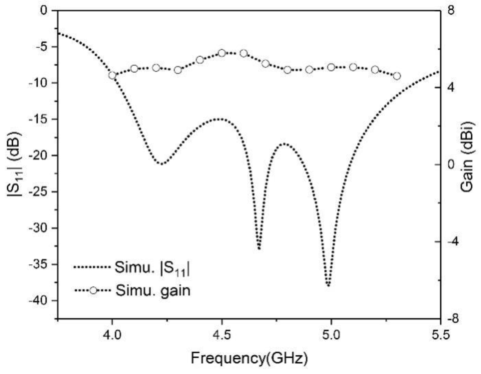
Figure 3.
Geometries of (a) bow-tie radiator in free space, (b) bow-tie radiator near the edge of a ground plane and (c) bow-tie radiator above a ground plane. (d) Simulated return losses of (a–c).
Figure 3.
Geometries of (a) bow-tie radiator in free space, (b) bow-tie radiator near the edge of a ground plane and (c) bow-tie radiator above a ground plane. (d) Simulated return losses of (a–c).
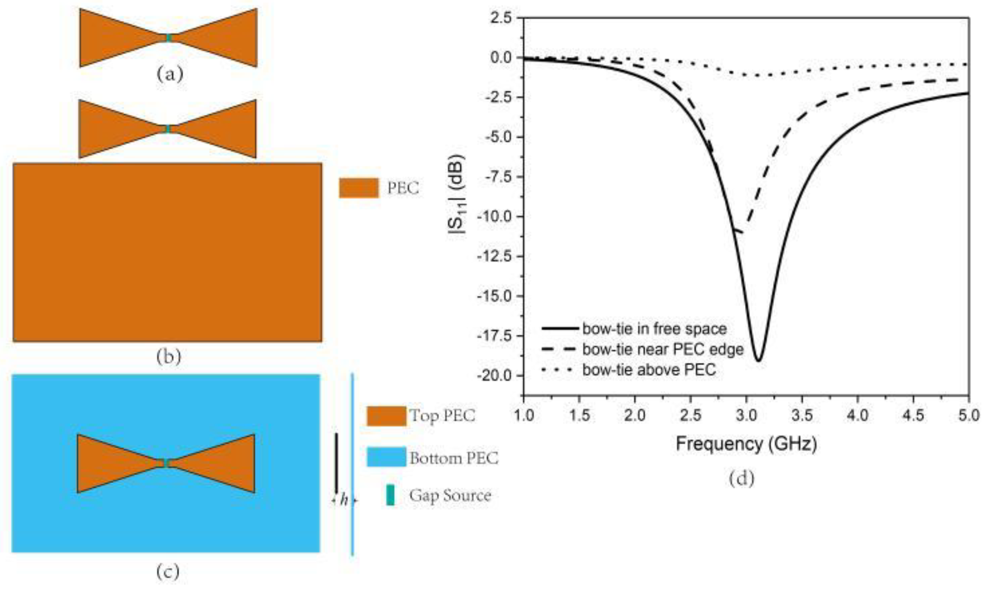
Figure 4.
Geometries of (a) bow-tie radiator near mushroom edge and (b) bow-tie radiator near PEC edge. (c) Simulated return losses of (a,b).
Figure 4.
Geometries of (a) bow-tie radiator near mushroom edge and (b) bow-tie radiator near PEC edge. (c) Simulated return losses of (a,b).
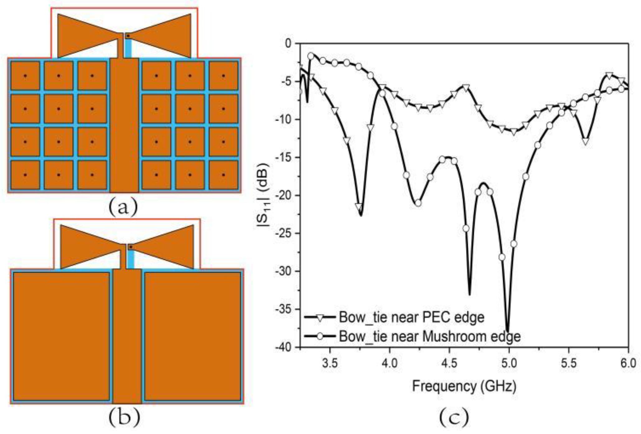
Figure 5.
Simulated reflection phase diagram of the mushroom unit cell along with its simulation setup.
Figure 5.
Simulated reflection phase diagram of the mushroom unit cell along with its simulation setup.
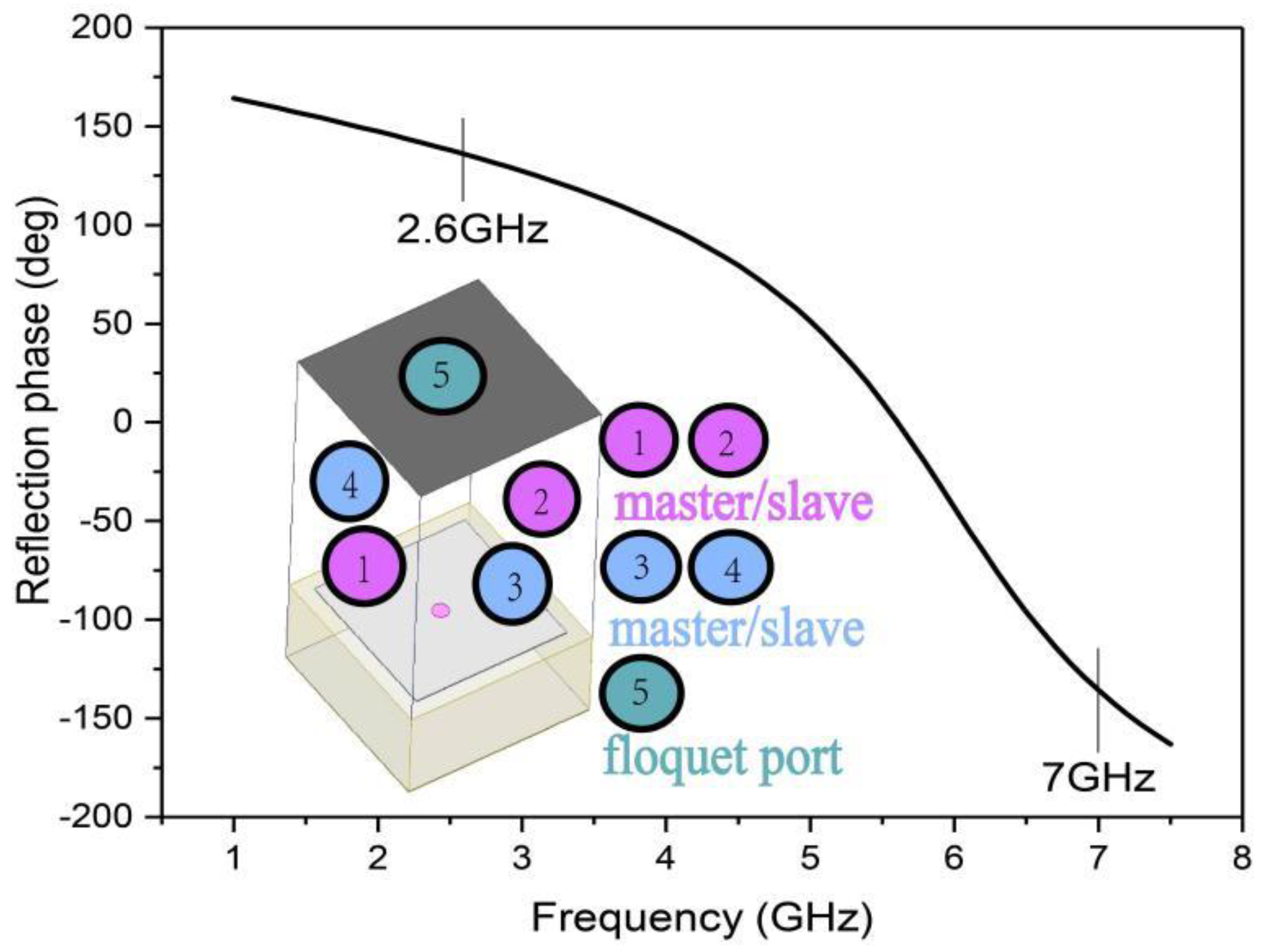
Figure 6.
Equivalent LC circuit model of mushroom-like metamaterial.
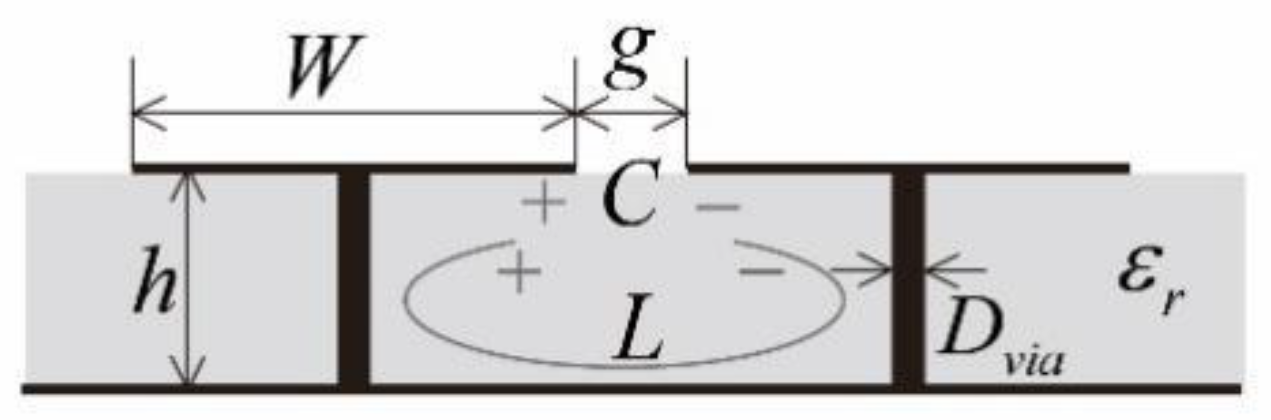
Figure 7.
(a) Photo of the fabricated MTM-based wideband antenna. (b) Simulated and measured and gain values.
Figure 7.
(a) Photo of the fabricated MTM-based wideband antenna. (b) Simulated and measured and gain values.

Figure 8.
Simulated and measured radiation patterns of MTM-based wideband antenna at (a) 4.8 GHz, x-z plane, (b) 4.8 GHz, y-z plane, (c) 5.2 GHz, x-z plane, (d) 5.2 GHz, y-z plane.
Figure 8.
Simulated and measured radiation patterns of MTM-based wideband antenna at (a) 4.8 GHz, x-z plane, (b) 4.8 GHz, y-z plane, (c) 5.2 GHz, x-z plane, (d) 5.2 GHz, y-z plane.

Figure 9.
Geometry of the proposed metamaterial and SIC structure-based array antenna and the coordinate system. (a) Top view. (b) Side view.
Figure 9.
Geometry of the proposed metamaterial and SIC structure-based array antenna and the coordinate system. (a) Top view. (b) Side view.
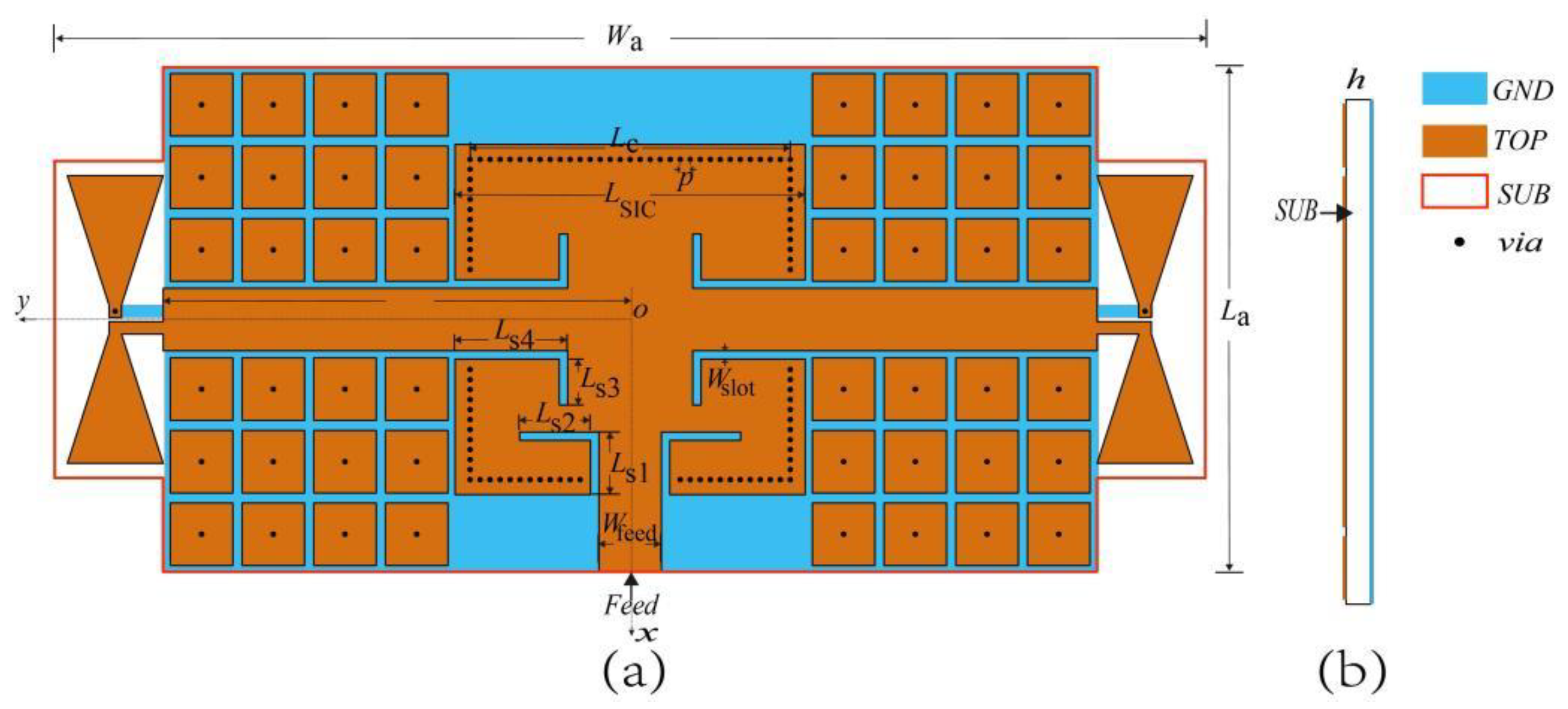
Figure 10.
Simulated of the proposed array antenna with varying bow-tie radiator size parameters. (a) varies with . (b) varies with .
Figure 10.
Simulated of the proposed array antenna with varying bow-tie radiator size parameters. (a) varies with . (b) varies with .
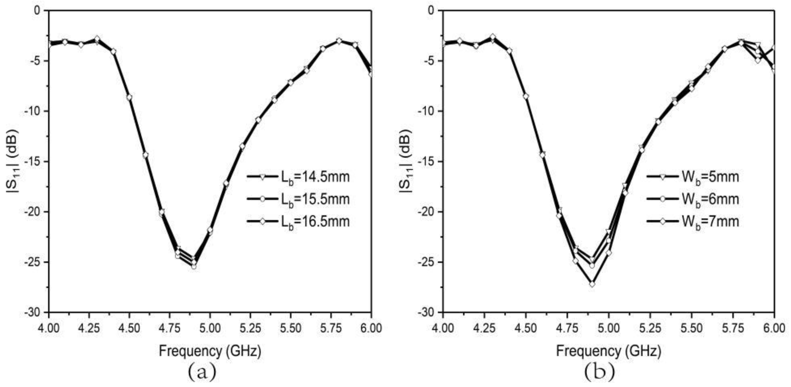
Figure 11.
Simulated of the proposed array antenna with different mushroom cell sizes .
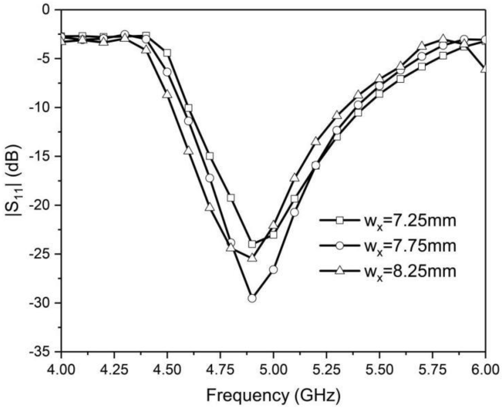
Figure 12.
In-phase diagram of mushroom unit cell with different top metal patch sizes .
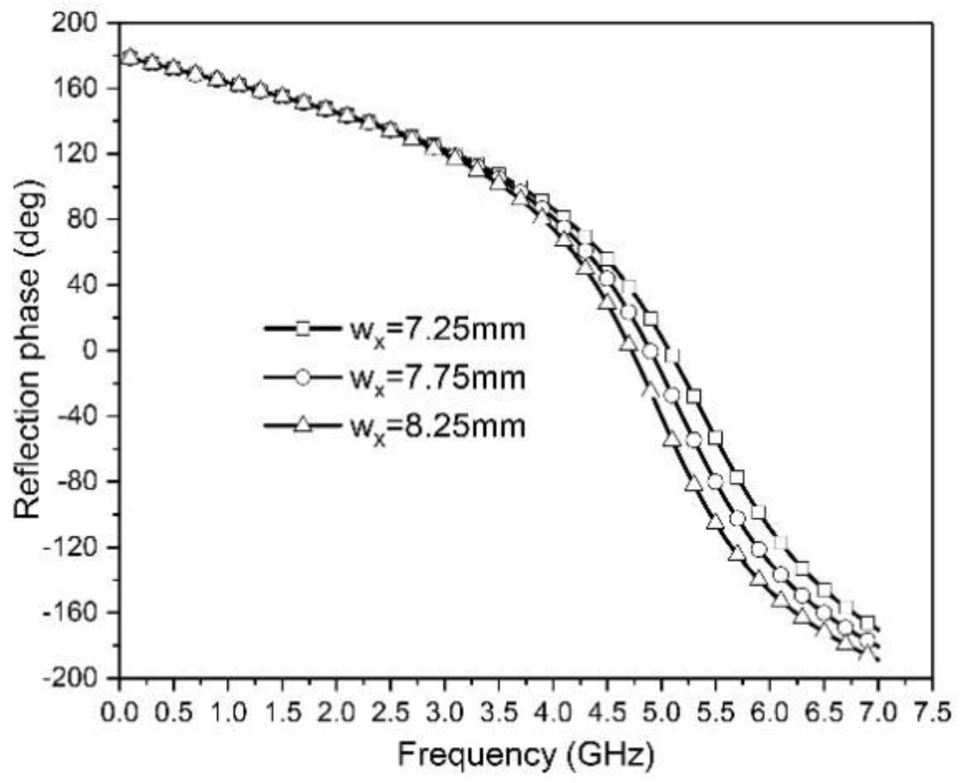
Figure 13.
(a) Geometry of T-shape power divider. (b) Simulated results of T-shape power divider. (c) Geometry of T-shape power divider-based array antenna. (d) Comparison results of SIC-based and T-shaped power divider-based array antennas.
Figure 13.
(a) Geometry of T-shape power divider. (b) Simulated results of T-shape power divider. (c) Geometry of T-shape power divider-based array antenna. (d) Comparison results of SIC-based and T-shaped power divider-based array antennas.
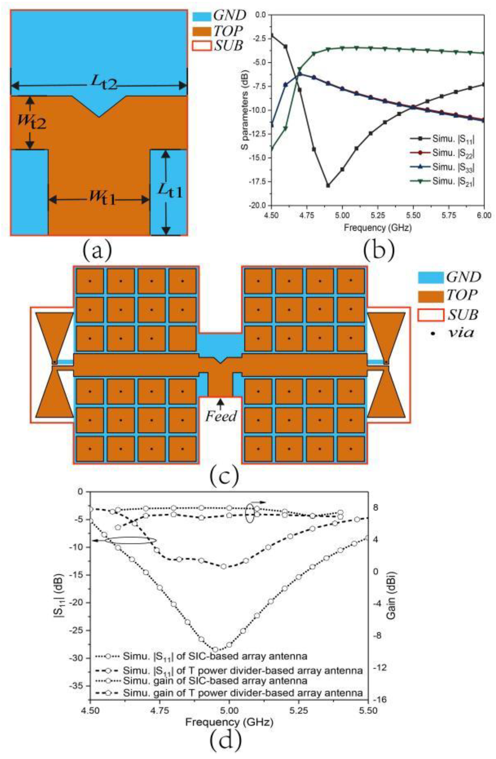
Figure 14.
Photo of the fabricated array antenna.
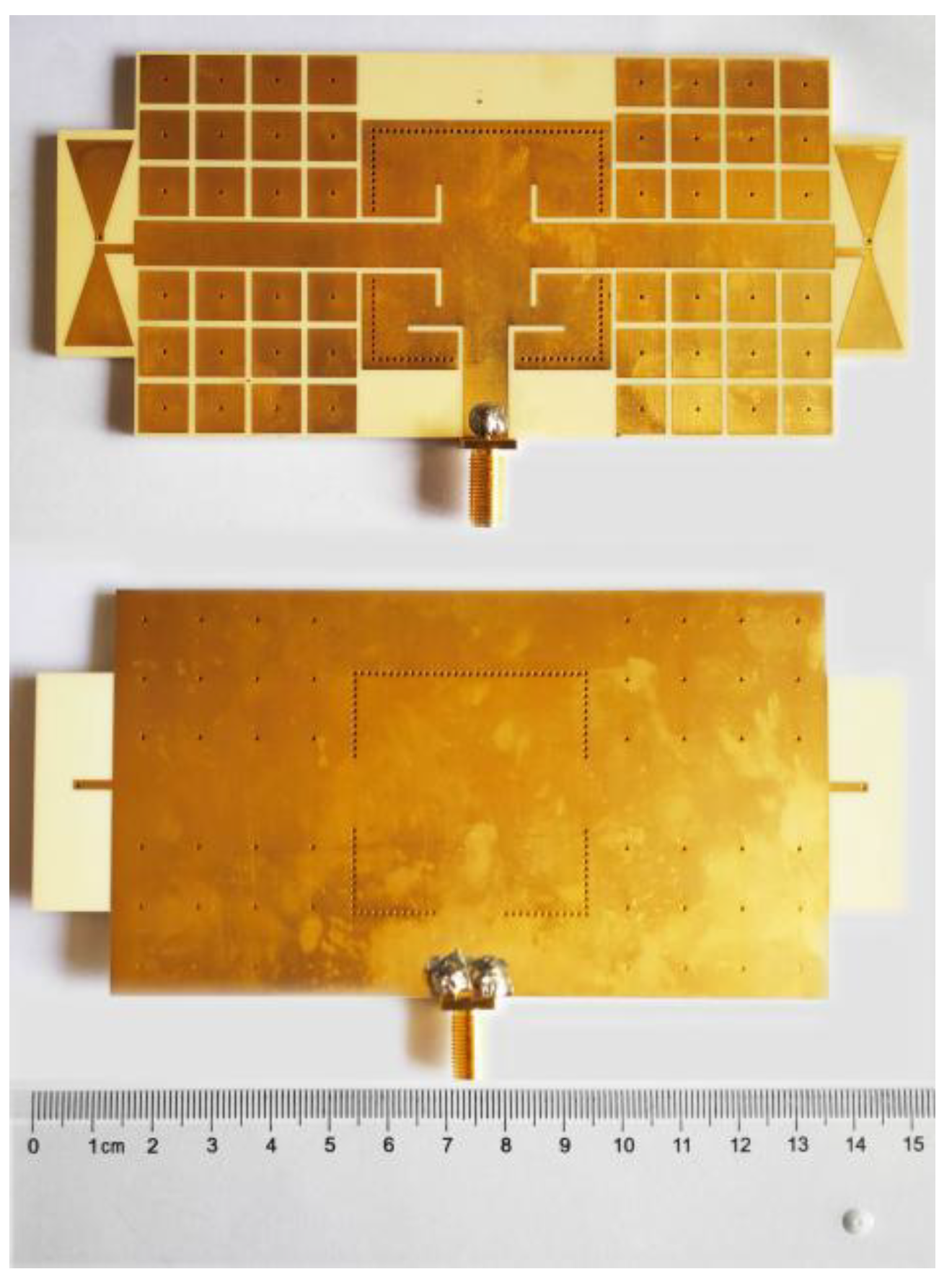
Figure 15.
Simulated and measured and gain values of proposed array antenna.
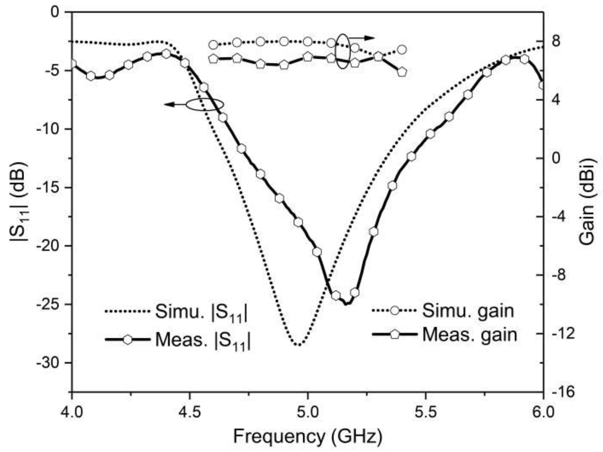
Figure 16.
Simulated and measured radiation patterns of array antenna at (a) 4.8 GHz, x-z plane, (b) 4.8 GHz, y-z plane, (c) 5.2 GHz, x-z plane, (d) 5.2 GHz, y-z plane.
Figure 16.
Simulated and measured radiation patterns of array antenna at (a) 4.8 GHz, x-z plane, (b) 4.8 GHz, y-z plane, (c) 5.2 GHz, x-z plane, (d) 5.2 GHz, y-z plane.
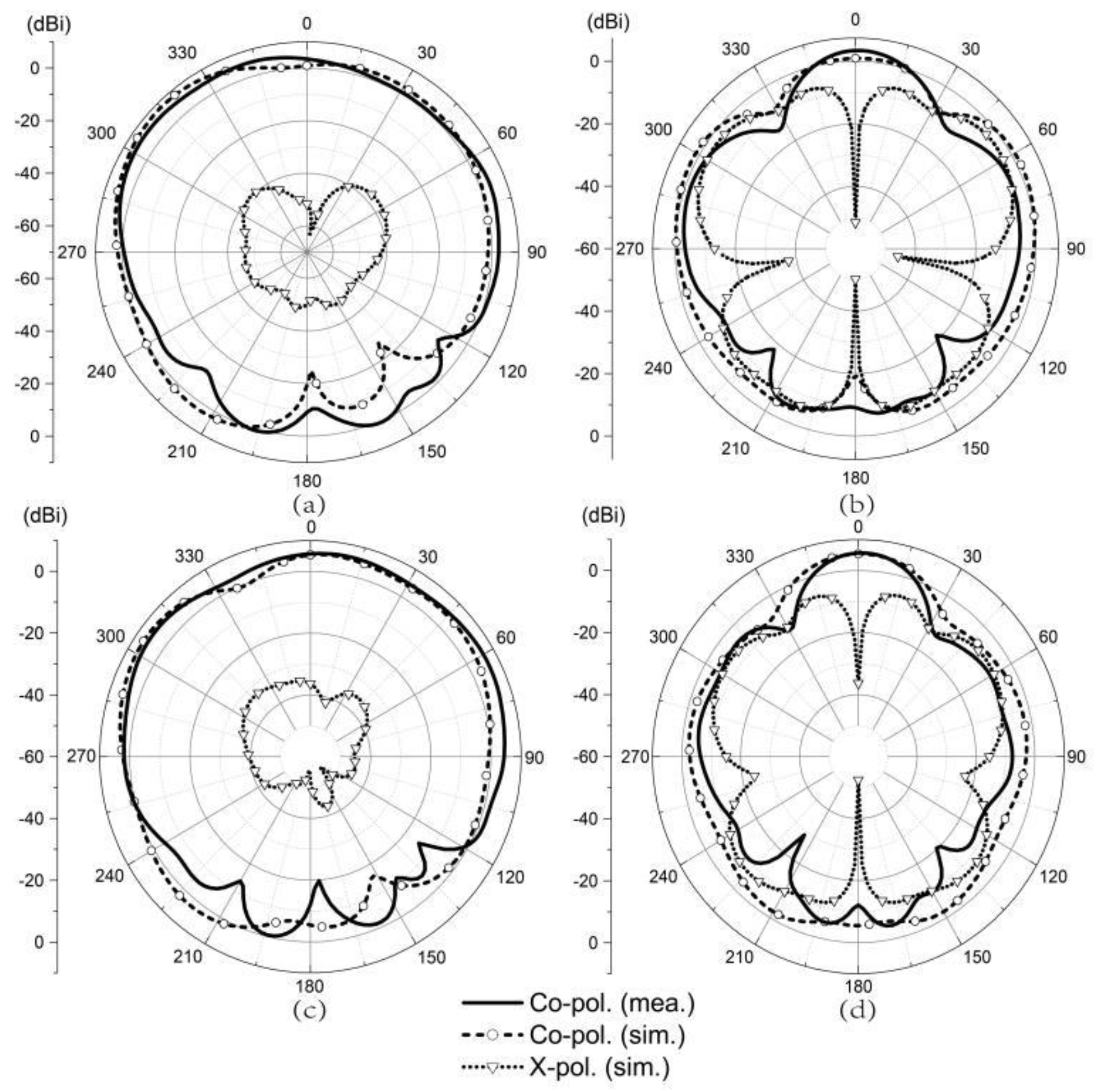
Figure 17.
Efficiency of the array antenna.


Table 1.
Parameter values of the wideband antenna shown in Figure 1 (unit: mm).
Table 1.
Parameter values of the wideband antenna shown in Figure 1 (unit: mm).
| Parameter | Value | Parameter | Value |
|---|---|---|---|
| 60.5 | 11.25 | ||
| L | 48 | 13 | |
| 7.5 | 1.1 | ||
| 7.5 | 1.2 | ||
| 1.5 | 0.85 | ||
| 8.75 | 0.75 | ||
| 5 | 15.5 | ||
| 7.5 | 38 |
Table 2.
Compared results between different types of antennas.
| References | [19] | [20] | [21] | [22] | [23] | [24] | This Work |
|---|---|---|---|---|---|---|---|
| Overall size () | 1.66× 1.0× 0.23 | 3.8× 0.28× 0.62 | 4.44× 2.22× 0.08 | 1.81× 0.20× 0.02 | 2.5× 2.5× 0.29 | 1.13× 4.0× 0.03 | 2.4× 1.08× 0.05 |
| Center frequency (GHz) | 2.2 | 5 | 8.32 | 4.8 | 2.5 | 5.75 | 5 |
| Bandwidth (%) | 45 | 14.5 | 11.78 | 16.3 | 17 | 2.7–6 | 17 |
| Realized gain (dBi) | 9 | 5 | 9.1 | 5.8 | 6.0–7.6 | 6–7.2 | 6.6 |
Publisher’s Note: MDPI stays neutral with regard to jurisdictional claims in published maps and institutional affiliations. |
© 2022 by the authors. Licensee MDPI, Basel, Switzerland. This article is an open access article distributed under the terms and conditions of the Creative Commons Attribution (CC BY) license (https://creativecommons.org/licenses/by/4.0/).
Share and Cite
MDPI and ACS Style
Wang, S.; Sun, L.; Ntawangaheza, J.d.D. An SIC-Fed Low-Profile Wideband Metamaterial-Based Antenna Array for 5G Wireless Cellular Networks. Designs 2022, 6, 43. https://doi.org/10.3390/designs6030043
AMA Style
Wang S, Sun L, Ntawangaheza JdD. An SIC-Fed Low-Profile Wideband Metamaterial-Based Antenna Array for 5G Wireless Cellular Networks. Designs. 2022; 6(3):43. https://doi.org/10.3390/designs6030043
Chicago/Turabian StyleWang, Shengjie, Liguo Sun, and Jean de Dieu Ntawangaheza. 2022. "An SIC-Fed Low-Profile Wideband Metamaterial-Based Antenna Array for 5G Wireless Cellular Networks" Designs 6, no. 3: 43. https://doi.org/10.3390/designs6030043