
Advanced Thermal Management Systems for High-Power Lithium-Ion Capacitors: A Comprehensive Review


1
Research Group MOBI, Mobility, Logistics, and Automotive Technology Research Centre, Vrije Universiteit Brussel, Pleinlaan 2, 1050 Brussels, Belgium
2
Flanders Make, 3001 Heverlee, Belgium
*
Author to whom correspondence should be addressed.
Designs 2022, 6(3), 53; https://doi.org/10.3390/designs6030053
Submission received: 16 May 2022
/
Revised: 30 May 2022
/
Accepted: 2 June 2022
/
Published: 9 June 2022
(This article belongs to the Special Issue Battery System Design)
Abstract
:The acceleration demand from the driver in electric vehicles (EVs) should be supported by high-power energy storage systems (ESSs). In order to satisfy the driver’s request, the employed ESS should have high power densities. On the other hand, high energy densities are required at the same time for EVs’ traction to minimize the range anxiety. In this context, a novel ESS has emerged that can provide high power and energy densities at the same time. Such technology is called lithium-ion capacitor (LiC), which employs Li-doped carbon as negative electrode and activated carbon as positive electrode. However, high heat generation in high current applications is an issue that should be managed to extend the LiCs life span. Hence, a proper thermal management system (TMS) is mandatory for such a hybrid technology. Since this ESS is novel, there are only several TMSs addressed for LiCs. In this review article, a literature study regarding the developed TMSs for LiCs is presented. Since LiCs use Li-doped carbon in their negative electrodes, lithium-titanate oxide (LTO) batteries are the most similar lithium-ion batteries (LiBs) to LiCs. Therefore, the proposed TMSs for lithium-ion batteries, especially LTO batteries, have been explained as well. The investigated TMSs are active, passive, and hybrid cooling methods The proposed TMSs have been classified in three different sections, including active methods, passive methods, and hybrid methods.
1. Introduction
The need for electrified vehicles has been more requested as the greenhouse gasses (GHG) and exhaust emissions are being increased [1]. In this context, pure electric vehicles (EVs) and hybrid electric vehicles (HEVs) have emerged. The main part of EVs and HEVs are energy storage systems (ESSs) such as lithium-ion batteries (LiBs) [2]. However, LiBs suffer from low specific power and limited lifetime [3]. On the other hand, supercapacitors (SCs) have high power densities and a long lifetime, but their specific energy is limited. Therefore, lithium-ion capacitors (LiCs) have emerged by combining the electrode materials of LiBs and SCs. LiCs have higher specific energy than SCs, and a longer lifetime and specific power than LiBs.
Although LiCs are attractive candidates to be employed in high-power use cases, the LiC’s high power density generates high amounts of heat loss [4], which is harmful for their lifetime and applicability [5]. Moreover, the high heat loss results in non-uniformed heat distribution. Such a phenomena affects the state of charge estimation and voltage unbalances within the batteries in the module [6]. The first action to extend the lifetime of LiCs while managing their safety and reliability is designing a robust TMS [7,8]. Such a proper design can be performed by analyzing the developed TMSs in the literature.
Figure 1 shows that the cell’s operating temperature affects its lifetime, performance, and safety [9]. As is seen, the chemical reaction inside the cell is the leading cause of temperature rise. The reaction rate would be increased with higher power output and capacity at high temperatures [10]. To the best of the author’s knowledge, the number of published works for the TMS design of hybrid ESS mainly LiCs is so limited. Therefore, the lithium-titanate oxide (LTO) battery that is the most similar lithium-ion battery to LiCs is also investigated. In this regard, some advanced TMSs for lithium-ion batteries are presented in this review article.
Figure 2 exhibits various types of TMSs addressed in the literature for the high-power LiCs. Although there are some other cooling types like refrigerant cooling or immersion cooling [11], these cooling methods have never been tested and reported for the LiC technology. Therefore, in this review paper, only the proposed and published cooling solutions for LiCs are presented. The proposed methods are active, passive, and hybrid cooling methods. In general, there are two types of TMS for ESSs in the literature, including active and passive methods. These two methods can be coupled to make a hybrid TMS [12]. Active cooling systems proposed for the LiCs include mixed air-cooled methods, forced air cooled methods, and liquid cooled methods. On the other hand, passive systems count heat sinks, heat pipes, and phase change materials (PCM). Although there are several passive cooling systems addressed in the literature for high-power applications, these systems are not a good solution where the current rate is high. Thus, the passive cooling systems are perfect candidates to be combined with active cooling systems to reduce the energy use of the cooling system. Therefore, the combination of active and passive cooling systems is of high importance, depending on the application. Additionally, the required cooling system’s volume, weight, and cost are influencing factors to select the most optimum cooling design.
In general, hybrid cooling systems combine active with active cooling systems, active with passive cooling systems, and passive with passive cooling systems. As there are air and liquid options for active cooling systems, the combination of air and liquid cooling systems generates the active-active hybrid TMS. However, as both systems are active, the power consumption of the TMS would not be logical. The optimal combinations for active and passive cooling systems would be air with heat sinks, heat pipes, or PCMs, while liquid can be combined with PCMs. This way, the power consumption or the inlet coolant flow rate can be minimized. Finally, the combination of passive with another passive TMS results in higher thermal performance. Nevertheless, the weight and volume of the system would be increased. This method can be an ideal solution where the power consumption needs to be minimized or become zero since passive TMS systems do not require any external power source to operate. The pure passive hybrid TMS PCM has a prominent role, while various heat sinks and heat pipes combinations can be considered.
2. Active Cooling Methods
The active cooling systems have enhanced heat transfer rates by using the flow rate during convection to increase the heat removal rate [13]. However, active TMSs are massive, complex, and costly to install compared to passive TMSs. In addition, active TMSs have many moving parts such as coolant pumps that will add some cost for the maintenance [14]. In this section, the most used active TMSs for vehicle applications are presented.
2.1. Air Cooling System
One of the most common active cooling systems is air cooling because of the simple structure and low cost. Nevertheless, due to the low heat transfer coefficient and thermal conductivity compared to the liquid cooling system, air cooling would be ineffective if the cooling parameters such as inlet flow rate, inlet flow temperature, inlet and outlet positions, and gap spacing between neighboring cells are not set accordingly [15].
Karimi et al. presented an optimal air-cooled solution for LiCs TMSs when they are being charged and discharged under high current rates of 150 A [16]. Under such a harsh current rate, the maximum temperature of the 2300 F LiC increases from 23 °C to 55.3 °C during 1400 s. Their proposed TMS could keep the maximum temperature of the LiC cell at 37.8 °C, meaning that the proposed air-cooled TMS could reduce the maximum temperature by 31.6% compared with the natural convection, where there is not any employed TMS. Moreover, they showed that increasing the inlet velocity from 2 m/s to 3 m/s leads to a temperature reduction from 37.8 °C to 32.1 °C. Figure 3 exhibits their proposed TMS. Nevertheless, by increasing the air inlet flow rate, the flow resistance would be enhanced, which will result in energy loss. There are some other parameters to be optimized for the air-cooling system, such as the inlet air and outlet air positions. However, in the mentioned article, the inlet and outlet positions have not been optimized.
Soltani et al. [17] developed a 3D heat model for a LiC module employing the air-cooled method as the TMS. His module was charged and discharged under a 100 A current rate that can be considered a mild-duty application for such high-power cells. The design parameters of the proposed TMS were optimized, including inlet air velocity, spacing between cells, and the direction of the flow. He proved that the side cooling with 5 m/s air velocity and 5 mm space between cells is the optimized air-cooled topology. There are no more research articles regarding the air-cooling system of LiCs based on our thorough literature review. Therefore, for future TMSs, some literature study for lithium-ion batteries in high power applications is presented below.
Karimi et al. [18] used a novel air-cooled method to maintain the temperature distribution and uniformity within a LiC module. Their module consists of ten 2300 F LiC cells in series connection. The temperature after 1400 s without any TMS reaches almost 70 °C, but, using the proposed air-cooling system with an inlet velocity of 2 m/s, reduced it to 43.7 °C. Although the final temperature has been diminished by 32.7%, the temperature uniformity was not acceptable (23.3 °C). Therefore, some optimization analysis has been conducted, including inlet velocity, inlet and outlet positions, space between cells, rotating the module, and combining these optimization parameters. In the best case, by combining the best optimization scenarios, the final temperature has been diminished to 27.5 °C, where the temperature uniformity between the hottest and coldest cells was 4.5 °C. Figure 4 shows the mentioned air-cooled method.
These three mentioned articles are the only TMSs for the LiC technology. However, the proper TMSs for high power applications have been presented below that can be used for LiCs as well. Zhang et al. [19] developed an air-cooled system based on multi-vents and optimized the system by changing the position, size, and several vents. It was seen that the temperature distribution and uniformity of the module reduced up to 16.6% and 76%, respectively.
Cheng et al. [20] developed an active method based on air for a battery module to decrease the mean temperature value, and the pressure loss of the system. He optimized the proposed air-cooled system using a Multi-objective Genetic Algorithm (MOGA) to find a balance between the thermal performance, size of the system, and energy use.
Xu et al. [21] proposed another active method based on air. His results proved that using double-layer plates reduces the temperature of the module up to 11% and the temperature difference up to 31.5%. Temperature uniformity is defined as the temperature difference between the coldest and hottest cells within a module or pack. Chen et al. [22] proposed a symmetrical active method based on air with low energy use and high performance. His results proved 43% and 33% temperature reduction and energy use, respectively.
2.2. Liquid Cooling System
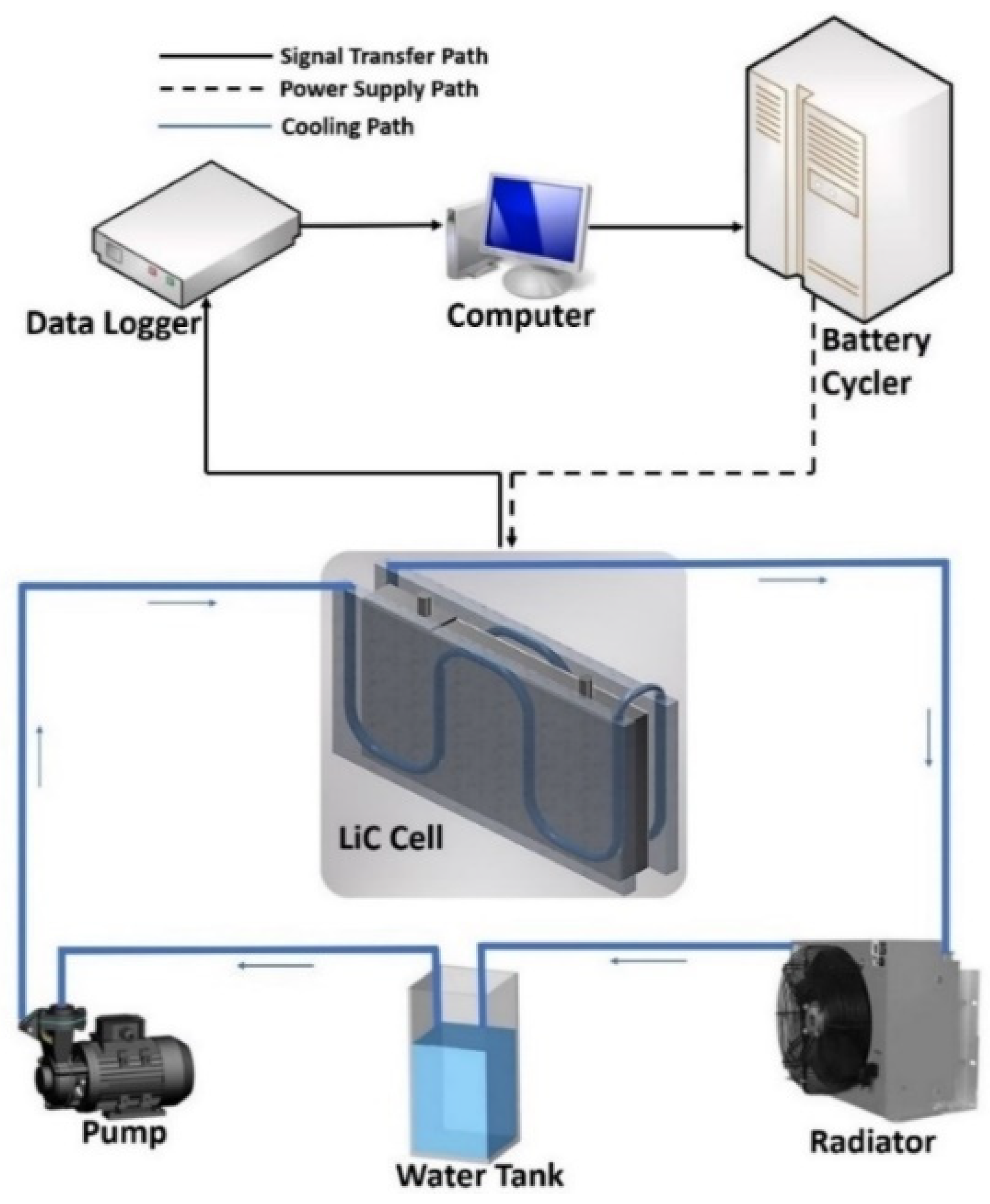
Another active cooling method is a liquid based system, with some fluids as the coolant media such as water or ethylene glycol [23,24,25]. Moreover, oil can be used as the coolant. Since liquid has higher heat transfer ratio than air, the thermal performance of liquid based methods is better than air based methods [26]. Karimi et al. [27] developed a compact liquid based system for a 2300 F LiC cell that can be seen in Figure 5. The proposed TMS reduced the LiC’s temperature from 55.3 °C to 32.5 °C. This means that the maximum temperature has decreased by 41.2%.
Additionally, they optimized the proposed liquid-cooled system considering the inlet flow rate, inlet coolant temperature, channel diameter, number of arcs in the coolant path, and influence of various types of thermal interface materials (TIM). The higher the inlet flow rate, the lower the maximum temperature, but also a higher pressure drop is achieved. In addition, by reducing the inlet coolant temperature, the maximum temperature would be reduced. In addition, by increasing the number of arcs per tube, pressure loss would be increased, but the temperature is diminished. In the end, the impact of TIM has been evaluated, for which, by increasing the thermal conductivity of TIM, temperature evolution is lowered. However, at some point, enhancing the thermal conductivity by more than 8 W/m.K has no impact on the temperature drop, but the cost of the system would be added. Therefore, a trade-off should be performed to reach the most optimal temperature while keeping the performance indicators of cost, weight, and volume as low as possible.
In another work, they investigated a liquid cooling method for LiCs. The module consisted of 12 LiCs in series connection [28]. Figure 6 illustrates the main case study before optimization cases, with temperature reduction from 70 °C to 40.3 °C. The uniformity of the hottest and coldest cells is 9.1 °C, which is not favorable. Therefore, some optimization cases should be designed to reduce the temperature difference. Enhancing the inlet flow rate from 100 mL/min to 1000 mL/min reduced the maximum temperature to 33.2 °C with a 5.1 °C temperature difference. Moreover, by enhancing the fluid temperature from 23 °C to 40 °C, the impact cannot affect the maximum temperature, but the temperature uniformity reached 1.4 °C. In addition, changing the inlet and outlet positions had a good influence on the temperature. Moreover, the number of arcs per tube has been evaluated, for which three arcs per coolant pipe has been selected as the optimal case. In the end, by optimizing the mentioned parameters, the maximum temperature has been maintained below 38 °C, with uniformity of 2 °C. Figure 7 exhibits the temperature distribution of the optimal scenarios.
Akbarzadeh et al. [29] compared two active cooling systems based on air and liquid methods. He showed that the uniformity of the module increases by enhancing the air inlet velocity, but employing the liquid cooling system would decrease this temperature difference. Considering the energy efficiency, the liquid-based system is more effective than the air-based system. When the liquid cooling system is used, the maximum temperature of the hottest cell is 3 °C lower than the air cooling system, with the same energy use. Moreover, the power consumption ratio should be 860 to increase the mean temperature by 13.5 °C. In another work, he used the same cooling system to be combined with PCM to reduce the energy use of the TMS [30].
Tang et al. [31] analyzed a liquid cooling TMS for EVs based on machine learning. Their cooling system efficiency was estimated based on a support vector regression model. Xu et al. [32] developed a liquid-based TMS for a battery pack. The optimized scheme reduced the temperature uniformity by 7.49% than the main case. Tan et al. [33] proposed numerical studies for a direct liquid cooling system for a fast charging LiB pack in hydrofluoroether. The temperature uniformity and standard deviation have been diminished by 18.1% and 25%, respectively. Akbarzadeh et al. [13] investigated a liquid-based TMS embedded with PCM that the new cold plate was able to reduce pump energy use and weight of the plate by 30% and 36%, respectively.
3. Passive Cooling Methods
Passive methods require low energy to operate when combined with other cooling methods, which results in a lower system cost, making it an appropriate system where the required peak power is low.
3.1. Heat Sink (Fin Structure)
Heat sinks are passive heat exchangers with the ability of heat removal by transferring it to the ambient. The heat removal process is performed by enhancing the heat flow away from a heat source. For battery modules/packs, heat sinks are not good candidates due to the low heat transfer rate. However, they can play a significant role in batteries’ heat removal as secondary material in hybrid TMSs. The number of research items investigating heat sinks alone as a cooling solution for LiCs and lithium-ion batteries is not extensive. However, some of them are summarized in this section. In the only research item for LiCs considering the usage of heat sinks as the proper TMS, an LiC cell is surrounded by two novel heat sinks in high power applications [34]. The experimental test bench and the numerical 3D model are shown in Figure 8. Such a passive TMS reduced the maximum temperature by 18.9%, which is a good performance. However, this reduction trend proves that, if heat sinks are used combined with the other TMSs, the results would be better.
Hosseinirad et al. [35] examined straight and wavy fins in miniature heat sinks as a TMS and proposed other interruptions for some case studies. The interrupted fin model had an enhancement of up to 98.1% compared with integral fin models. Nguyen et al. [36] developed a wall integrated fin feature for a prismatic LiB cell. They identified the deformation battery role in the thermal performance of electric vehicles.
Liu et al. [37] proposed a novel tree-like heat sink for TMS of an LiB cell stack, in which the impact of geometric parameters was investigated. Zhang et al. [38] compared different fin geometries under natural convection to study the effect of surface anodization on thermal radiation. The thermal performance of his developed system enhanced notably up to 27% after anodization. Pan et al. [39] designed a manifold microchannel heat sink. They compared the designed heat sink with traditional ones and proposed the index of temperature uniformity and investigated the main influencing factors of heat sinks. By having a look at the results, one can understand that the performance of two heat sinks is alike, but the pressure drop differs. The traditional heat sink has 8.23 times more pressure drop than the new heat sink when the inlet flow rate is 100 mL/min.
3.2. Phase Change Materials (PCM)
Phase change materials (PCMs) absorb thermal energy during the phase transition from the solid phase to the liquid phase with minimal temperature rise [40]. The latent heat is higher than the sensible energy stored thanks to the material’s specific liquid or solid phase heat [41]. The latent heat of fusion of PCMs is quite high, which leads to absorbing a high amount of thermal energy while retaining a constant temperature [42]. During the PCM’s phase change, the specific heat would be increased when it starts to be melting from the solid state. Figure 9 illustrates the working principle of PCMs.
PCMs’ maintenance is not required because they do not have any moving parts. Moreover, there is no external energy source for PCMs to work. Paraffin is the most employed material as the PCM due to its valuable advantage of having a long life since paraffin is chemically compatible with metals [43]. The concept of using PCMs as TMS in batteries for the first time was presented by Al-Hallaj et al. [44]. Gradually, the excellent properties of PCMs for the thermal management of batteries have been revealed [45]. Karimi et al. [46] employed a paraffin-based PCM for a dual cell module of LiCs. The proposed passive system decreased the maximum temperature of the module by 26%, in which the temperature reduced from 55.3 °C to 40.8 °C. Moreover, they used an aluminum mesh grid foil to increase the thermal properties of the PCM, and thus the temperature was reduced to 36.2 °C. Figure 10 illustrates the employed PCM for the LiC technology.
Jaguemont et al. [47] used a paraffin wax for LiC cooling system and defined three case studies, including natural air (zero-strategy), cooling with PCM, and cooling with PCM-Al (Figure 11). They showed that enhancing the thermal conductivity of the PCM is of high importance since PCMs can absorb the generated heat easily, but they have problems rejecting the absorbed heat to the ambient. However, almost all PCMs suffer from low thermal conductivity. Therefore, many researchers targeted to overcome this issue by using different methodologies. Therefore, other high conductive materials such as heat pipe [48], graphite [49], nanomaterials [50], nanofluids [51], copper foams [52], or aluminum foams [46] should be added to PCM to cope with this drawback. Table 1 lists the summary of the composite PCMs in the literature.

Table 1.
Summary of the composite PCMs in the literature.
| Composite PCM | Author | Impacts |
|---|---|---|
| PCM/Graphite foam (GF) | [53] | Lower porosity values lead to higher heat transfer through conduction, impact on melting and solidification time. |
| PCM/Alcohol/graphite foam (GF) | [54] | 24% extension effect on temperature control, lower melting point. |
| PCM/biochar (BC), activated carbon (AC), carbon nanotubes (CNT), expanded graphite (EG) | [55] | High thermal stabilities up to 150 °C for all composites, improvement in the loading ratio and thermal characteristics, low PCM loading capacity, and high confinement in the BC- and AC-based composite PCMs. |
| PCM/Graphite | [56] | high potential to supply the required thermal energy. |
| PCM/Infiltrated GF (IGF) | [57] | 40 times higher thermal conductivity. |
| PCM/EG and Expanded Vermiculite | [58] | 114.4% rise in thermal conductivity, 25.9% faster heating, and 19.2% faster cooling. |
| PCM/Heat sink | [59] | 11.2% and 78.3% reduction in the maximum temperature and temperature standard deviation. |
| PCM/low melting point alloy (LMPA) heat sink | [60] | Improvement in the melting process synchronization, prolonging the melting time, added cost and weight. |
| PCM/Heat pipe | [61] | 33.1% reduction in the heat source temperature. |
| PCM/Nanofluid | [62] | 97% phase transition to liquid PCM that provided the highest stored thermal energy, PCM melting of 90% in 60 min. |
| PCM/porous media/nanofluid | [63] | 47% higher thermal performance, 33% drop in thermal resistance. |
| PCM/Copper foam | [64] | 44 times larger thermal conductivity. |
| PCM/Aluminum foam | [65] | 28% shorter melting time. |
| PCM/Nickel foam | [64] | 5 times larger thermal conductivity. |
3.3. Heat Pipe
The heat pipe cooling method is employed for the thermal management of batteries in some research articles. Heat pipes are passive devices with high thermal conductivity, low costs, no needs for maintenance, and lightweight. Various parts of a heat pipe are container, wick structure, and working fluid transport. Karimi et al. [66] designed a heat pipe TMS for LiCs, which is shown in Figure 12. They used flat heat pipes with 100 W cooling power and 8212 W/m.K thermal conductivity. Their results proved that heat pipe TMSs can reduce the temperature distribution by 17.7%. Nevertheless, the maximum temperature of the LiC cell was still far above 40 °C (the safe limit). Thus, this system alone is not capable of controlling the LiC’s temperature in high power applications.
To the authors’ knowledge, there is not any other developed heat pipe based TMS for LiCs. Some advanced TMSs for high power applications of lithium-ion batteries are then presented below that can also be used for the LiC technology. He et al. [67] designed a TMS based on heat pipes and investigated the aluminum sheet’s multiple structure parameters using fuzzy grey relation analysis. The optimum temperature value for his experiments was 37.5 °C with a 3.6 °C temperature difference between cells. Alihosseini and Shafaee [68] made a heat pipe for LiBs and obtained its equivalent circuit resistance through experiments. The designed heat pipe could control the temperature of the LiBs below 40 °C.
Liang et al. [69] evaluated a flat heat pipe to study the aging mechanism of a battery module. He controlled the battery pack temperature under 50 °C with a temperature uniformity of 5 °C. Jiaqiang et al. [70] analyzed the performance of a heat pipe TMS for a LiB pack and controlled the maximum temperature of 15 °C in 682 s and 375 s at 1C and 4C discharge rates, respectively. Wang et al. [71] investigated a micro heat pipe array for LiBs and enhanced the uniformity by less than 3.03 °C. Jouhara et al. [72] investigated a heat pipe TMS for a battery pack under a 6C discharge rate and controlled the maximum temperature below 30 °C for horizontal configuration and below 28 °C for vertical configuration.
4. Hybrid Cooling Methods
The most critical problem of battery modules is temperature uniformity, which can be solved by a robust TMS [73]. Active cooling systems can efficiently control the maximum temperature but require more power consumption than average if the aim is to minimize the temperature uniformity. In this regard, a hybrid system can reduce the temperature difference between the module cells while saving power consumption.
There are three sets of combinations for active and passive systems in the literature, summarized in Table 2. To the best of the authors’ knowledge, TMSs for the LiC technology are seldom reported in the literature. Therefore, first, the published papers on TMS development of LiCs have been presented, and then advanced research articles regarding the thermal modeling and cooling solution designs for lithium-ion batteries in high power applications have been reported. The presented hybrid TMSs in the literature are developed to decrease the maximum temperature and minimize the temperature uniformity of LiCs during high power applications.
Table 2.
Summary of the hybrid TMSs (HTMS) in the literature (NC means natural convection).
| Author | Hybrid Type | Configuration | C-Rate | Tmax (NC/HTMS) | ΔTmax |
|---|---|---|---|---|---|
| Rao et al. [74] | Liquid/PCM | Module | 5C | 88.2 °C/47.4 °C | 6 °C |
| Behi et al. [75] | PCM/Heat pipe | Cell 2.7 V | 8C | 56 °C/33.2 °C | 1.9 °C |
| Wu et al. [76] | Heat pipe/PCM | Module 16 V | 5C | 63.1 °C/50.9 °C | 2 °C |
| Lei et al. [77] | Liquid/Heat pipe/PCM | Module 7.3 V | 1.92C | 67 °C/47.9 °C | 10.9 °C |
| Behi et al. [78] | Air/Heat pipe | Cell 2.7 V | 8C | 57 °C/34 °C | 3 °C |
| Zhao et al. [59] | Heat sink/PCM | Module 28 kW/m3 | - | 40.8 °C/34 °C | 1 °C |
| Zhao et al. [59] | Air/Heat sink/PCM | Module 28 kW/m3 | - | 40.8 °C/31.8 °C | 0.6 °C |
| Behi et al. [79] | Air/Heat pipe | Module 33.7 V | 1.5C | 64.8 °C/37.1 °C | 2.3 °C |
| Yue et al. [80] | Liquid/Air/Heat pipe | Module 18.2 V | 3C | 37.5 °C/29.6 °C | 1.6 °C |
| Yang et al. [81] | Liquid/Air | Module 2 Ah | 4C | 53.8 °C/31.8 °C | 4.1 °C |
| Behi et al. [82] | Liquid/Heat pipe | Module 40.5 V | 8C | 56.7 °C/38.2 °C | - |
| Cao et al. [83] | Liquid/PCM | Module 27.5 V | 4C | 88.2 °C/55 °C | 5 °C |
| Situ et al. [84] | Air/PCM/metal foam | Module 16 V | 5C | 74.5 °C/52.8 °C | 3 °C |
| Qin et al. [85] | Air/PCM | Module 11 V | 2C | 70.2 °C/35 °C | 7.5 °C |
| Behi et al. [86] | Air/Heat pipe | Module 81 V | 8C | 58.8 °C/44.8 °C | - |
| Wang et al. [87] | Air/Heat sink | Module 26.4 V | 3C | 50.5 °C/40 °C | 5 °C |
4.1. Passive-Passive Hybrid Systems
Combining two passive cooling methods together results in a bulkier system, in which the cost of the final solution might be increased. However, this combination can control the maximum temperature of LiCs in high-power applications. The first passive-passive hybrid TMS for LiCs can be seen in Figure 13, in which PCM and six flat heat pipes have been combined together [48]. The results prove that, by using a single heat pipe cooling system or single PCM solution, the maximum temperature of the cell reduces by 17.7% and 26.2%, respectively. By combining these two systems, the maximum temperature is reduced by 35.8% compared with the natural convection scenario. Their temperature trend shows that the final temperature is kept around 35.8 °C under high current rates.
In another hybrid passive-passive system for LiCs, a heat sink is added to the PCM to increase the PCM’s thermal conductivity [41]. The schematic of the PCM-heat sink test bench is illustrated in Figure 14. The heat sink alone helps cool down the cell so the LiC’s temperature decreases to 44.8 °C, which is an 18.9% temperature reduction compared to the NC. Nevertheless, the heat sink alone is not considered to control the temperature contour fully. In addition, the PCM can control the cell’s maximum temperature, around 40.8 °C. Therefore, combining these two solutions reduced the maximum temperature by 38.3%. The cell’s maximum temperature reaches 34.1 °C, which has a 3.1% better performance than the hybrid PCM-heat pipe that has been presented above.
The thermal efficiency of the hybrid PCM-heat sink is compared with the hybrid PCM-heat pipe in Table 3. As is seen, using PCM, heat sink, or heat pipe alone cannot guarantee the safe operation of the LiC under high current rates. Using a hybrid PCM-heat pipe and hybrid PCM-heat sink decreases the maximum temperature by 35.2% and 38.3%, respectively. Therefore, the novel proposed heat sink has better thermal performance than the flat heat pipes. This trend can be seen from the table, both when using it alone or in combination with the PCM. When using the heat sink alone, its thermal performance is 1.2% more than six flat heat pipes in high-power applications. In addition, when using the same heat sink combined with another passive system like the paraffin PCM, its thermal performance is 3.1% higher than the hybrid heat pipes with the same paraffin PCM. The main conclusions in these two investigated hybrid TMSs prove that, although the thermal conductivity of heat pipes is far higher than aluminum heat sinks, the design and geometrical shape of heat sinks have a vital role in their performance.
The thermal energy storage of PCMs combined with heat pipes has been investigated in [88]. The heat pipes were used as superheat conductors to enhance the charge and discharge rate. Figure 15 shows the PCM solidification, the simulation results of the temperature evolution, and liquid fraction of the PCM at a 23 °C discharge process. During 4200 s, thermocouples at the 6 mm radius sense 31 °C, while the thermocouples at the 13 mm radius in the mushy zone sense 40 °C. Overall, hotter thermal bath temperature leads to lower phase change time.
The thermal performance of various scenarios for high-power LTO cells has been evaluated in [89]. The scenarios include Al mesh, copper mesh, PCM, and hybrid PCM-graphite, which are shown in Figure 16. The results exhibit that the average temperature of the cell due to NC, Al mesh, Copper mesh, PCM, and PCM-graphite compared with the lack of NC was reduced by 6.4%, 7.4%, 8.8%, 30%, and 39.3%, respectively.
4.2. Active-Passive Hybrid Systems
The main benefit of combining an active TMS with a passive one would be minimizing the energy use or the power consumption of the TMS. In this regard, some research items can be found in the literature considering the active-passive TMS development for the LiCs in high power applications. Air was added to the heat sinks to reduce the inlet flow rate of the air by having high-thermal conductive heat pipes [41]. The thermal conductivity of the used heat pipes is 8212 W/m.K. Therefore, the generated heat of the cell during an applied high current rate can be absorbed quickly by the heat pipes while air is blowing to the heat pipes to remove the absorbed heat. By having an initial temperature of 23 °C, the maximum temperature of the LiC cell increases only 5 °C and reaches 28 °C. This trend shows that the proposed hybrid air cooling and heat pipes not only can reduce the power consumption, but also can keep the maximum temperature far lower than the safe operating limit announced by the manufacturer. They also studied the combination of an air-cooling system and PCM, in which the proposed hybrid system could keep the maximum temperature of the LiC at 35.7 °C, meaning that 35.4% improvement has been achieved compared with the natural convection case study.
The combination of a liquid cooling system and PCM was first presented for a LiC module in a Ph.D. thesis [41]. This hybrid active-passive TMS is illustrated in Figure 17. The results proved that the module with such a hybrid active-passive TMS can experience a lower temperature difference between the hottest and coldest cells within a module. The maximum temperature of the module under natural convection reaches almost 70 °C, which, operating under such a high temperature, will result in thermal runaway. Therefore, the hybrid TMS is proposed that can keep the maximum temperature of the module at 39.4 °C. In addition, the coldest cell experiences a 3.4 °C lower temperature, meaning that the temperature uniformity of the module employing such a hybrid TMS is in a very good range.
Another hybrid active-passive TMS can be a combination of air and heat sinks. The thermal performance of a combined air cooling with extruded large heat sinks has been presented in [90]. Figure 18 depicts the experimental test setup of the system with high-power batteries in discharge mode. The results showed that, when the large heat sink is employed, the maximum temperature of the cell is reduced by 25.4%. Moreover, the air cooling system alone can reduce the maximum temperature by 37.1%. By having a hybrid TMS using the air cooling and heat sink, the maximum temperature of the cell is decreased by 45.5%. In addition, the power consumption of the active air-cooling system is reduced by almost 38%. Therefore, hybridization of the TMS can reduce the temperature and the power consumption. However, the cost of the system would be increased, which should be investigated.
Another hybrid TMS that investigated an air-cooling system combined with heat sinks is reported in [91]. The aluminum heat sink is used to increase the heat transfer rate. The discharge current rate of the LTO target cell was 184 A, which can be considered as a super-fast charging regime. Without any TMS, the LTO battery experiences a hot temperature of 56 °C. They had three scenarios of A, B, and C, for which the maximum temperature has been reduced by 39.6%, 40.9%, and 38.4%, respectively. These trends are presented and compared with the natural convection case study when there was not any TMS. Figure 19 depicts the LTO battery with the position of the K-type thermocouples, the thermal image picture, and temperature evolution under an 8C discharge rate.
Another active-passive hybrid TMS can be combining the liquid cooling system with PCM to reduce the energy use of the active cooling system, and at the same time increase the thermal conductivity of the PCM. In this context, an advanced hybrid TMS for LTO module under 4C rate is presented in [92]. The LTO module consisted of 30 cells in series. The melting area of the PCM was 34–36 °C with the highest operating temperature of 70 °C. The cooling media in the cooling system was water. The maximum temperature of the module without any TMS reached almost 44 °C, starting from 25 °C initial temperature. By using only PCM solution, the temperature reaches almost 36.2 °C, showing 15.8% improvement. However, the hybrid TMS can reduce the maximum temperature by 26% where the temperature is kept at 31.8 °C. The comparison is shown in Figure 20 for the natural convection (NC), PCM, and a hybrid PCM-liquid system.
4.3. Active-Active Hybrid Systems
The aim of combining two active TMSs can be keeping the maximum temperature as low as possible in very high dynamic current rates. This system was tested only once for the LiC cells [41]. The author first tested only the air-cooling strategy and only the liquid cooling strategy to understand the thermal response of these two systems for LiCs. Then, he proposed a hybrid TMS by combining these two active cooling systems. Figure 21 compares these three TMSs with natural convection (NC). Under the same applied high current rates, the maximum temperature of the cell under NC reaches 55.3 °C, while using the air cooling and liquid cooling systems reduce the maximum temperature by 31.6% and 41.2%, respectively. Combining these two TMSs leads to exceptional results showing that the maximum temperature can be maintained at 27.9 °C. This result proves a 49.5% improvement in the thermal response of the hybrid active-active TMS compared to the natural convection case study. Therefore, it can be concluded that using such an active-active TMS is a perfect solution when the applied current rate or the requested acceleration from the driver is too high.
5. Conclusions
In the present review article, the target cell was the new hybrid lithium-ion capacitor (LiC) that is a combination of supercapacitors and lithium-ion batteries. Such a hybrid technology can operate at high current rates in high power applications. Nevertheless, the main issue in such high-power rates is hot spots during fast charging and discharging. Therefore, a robust TMS is needed to control the maximum temperature of the LiC cell/module. In this context, in this review paper, the most advanced developed TMSs have been reviewed and presented in electric vehicle applications. Since the LiC technology is almost novel, the developed TMSs for such a technology are not sufficient. Therefore, the other articles that developed a TMS in high power applications for electric vehicles have been reviewed. These TMSs can be used for the LiC technology as well because the main aim is to keep the maximum temperature of the module/pack. Therefore, the proposed TMSs for lithium-ion batteries, especially LTO batteries, have been explained as well. The investigated TMSs are active, passive, and hybrid cooling methods. The proposed TMSs have been classified in three different sections, including active methods, passive methods, and hybrid methods.
Author Contributions
Conceptualization, methodology, investigation, writing—original draft preparation by D.K.; writing—review and editing, H.B., M.B. and J.V.M.; supervision, M.B. and J.V.M. All authors have read and agreed to the published version of the manuscript.
Funding
This research received no external funding.
Institutional Review Board Statement
Not applicable.
Informed Consent Statement
Not applicable.
Data Availability Statement
Not applicable.
Acknowledgments
The authors would like to thank Flanders Make for the support to our research group; MOBI.
Conflicts of Interest
The authors declare no conflict of interest.
References
- Van Mierlo, J.; Berecibar, M.; El Baghdadi, M.; De Cauwer, C.; Messagie, M.; Coosemans, T.; Jacobs, V.A.; Hegazy, O. Beyond the state of the art of electric vehicles: A fact-based paper of the current and prospective electric vehicle technologies. World Electr. Veh. J. 2021, 12, 20. [Google Scholar] [CrossRef]
- Khaleghi, S.; Hosen, M.S.; Karimi, D.; Behi, H.; Beheshti, S.H.; Van Mierlo, J.; Berecibar, M. Developing an online data-driven approach for prognostics and health management of lithium-ion batteries. Appl. Energy 2022, 308, 118348. [Google Scholar] [CrossRef]
- Hosen, M.S.; Karimi, D.; Kalogiannis, T.; Pirooz, A.; Jaguemont, J.; Berecibar, M.; Van Mierlo, J. Electro-aging model development of nickel-manganese-cobalt lithium-ion technology validated with light and heavy-duty real-life profiles. J. Energy Storage 2020, 28, 101265. [Google Scholar] [CrossRef]
- Musolino, V.; Tironi, E. A comparison of supercapacitor and high-power lithium batteries. In Proceedings of the Electrical Systems for Aircraft, Railway and Ship Propulsion (ESARS 2010), Bologna, Italy, 10 December 2010. [Google Scholar] [CrossRef]
- Miki, M.; Taguchi, Y. Reduction of current and rise in temperature of lithium ion battery combined with lithium ion capacitor. In Proceedings of the 2014 IEEE Vehicle Power and Propulsion Conference (VPPC), Coimbra, Portugal, 9 February 2015; pp. 1–3. [Google Scholar] [CrossRef]
- Jin, L.; Tian, J.; Gao, S.; Xie, P.; Akbarzadeh, M.; Kalogiannis, T.; Berecibar, M.; Lan, Y.; Hu, D.; Ding, Y.; et al. A novel hybrid thermal management approach towards high-voltage battery pack for electric vehicles. Energy Convers. Manag. 2021, 247, 114676. [Google Scholar] [CrossRef]
- Hosen, M.S.; Kalogiannis, T.; Youssef, R.; Karimi, D.; Behi, H.; Jin, L.; Van Mierlo, J.; Berecibar, M. Twin-model framework development for a comprehensive battery lifetime prediction validated with a realistic driving profile. Energy Sci. Eng. 2021, 9, 2191–2201. [Google Scholar] [CrossRef]
- Khaleghi, S.; Karimi, D.; Beheshti, S.H.; Hosen, S.; Behi, H.; Berecibar, M.; Mierlo, J. Van Online health diagnosis of lithium-ion batteries based on nonlinear autoregressive neural network. Appl. Energy 2021, 282, 116159. [Google Scholar] [CrossRef]
- Pesaran, A.A.; Keyser, M.; Kim, G.; Santhanagopalan, S.; Smith, K. Tools for Designing Thermal Management of Batteries in Electric Drive Vehicles Battery Temperature in xEVs. In Proceedings of the Advanced Automotive Battery Conference, Pasadena, CA, USA, 4–8 February 2013. [Google Scholar]
- Karimi, D.; Behi, H.; Van Mierlo, J.; Berecibar, M. A Comprehensive Review of Lithium-Ion Capacitor Technology: Theory, Development, Modeling, Thermal Management Systems, and Applications. Molecules 2022, 27, 3119. [Google Scholar] [CrossRef]
- Karimi, D.; Behi, H.; Jaguemont, J.; Berecibar, M.; Van Mierlo, J. A refrigerant-based thermal management system for a fast charging process for lithium-ion batteries. In Proceedings of the International Conference on Renewable Energy Systems and Environmental Engineering, Brussels, Belgium, 17–18 December 2020. [Google Scholar]
- Karimi, D.; Behi, H.; Van Mierlo, J.; Berecibar, M. Novel Hybrid Thermal Management System for High-Power Lithium-Ion Module for Electric Vehicles: Fast Charging Applications. World Electr. Veh. J. 2022, 13, 86. [Google Scholar] [CrossRef]
- Akbarzadeh, M.; Jaguemont, J.; Kalogiannis, T.; Karimi, D.; He, J.; Jin, L.; Xie, P.; Van Mierlo, J.; Berecibar, M. A novel liquid cooling plate concept for thermal management of lithium-ion batteries in electric vehicles. Energy Convers. Manag. 2021, 231, 113862. [Google Scholar] [CrossRef]
- Jiang, Z.Y.; Qu, Z.G. Lithium–ion battery thermal management using heat pipe and phase change material during discharge–charge cycle: A comprehensive numerical study. Appl. Energy 2019, 242, 378–392. [Google Scholar] [CrossRef]
- Rao, Z.; Wang, S. A review of power battery thermal energy management. Renew. Sustain. Energy Rev. 2011, 15, 4554–4571. [Google Scholar] [CrossRef]
- Karimi, D.; Behi, H.; Jaguemont, J.; Berecibar, M.; Van Mierlo, J. Optimized air-cooling thermal management system for high power lithium-ion capacitors. Energy Perspect. 2020, 1, 93–105. [Google Scholar]
- Soltani, M.; Berckmans, G.; Jaguemont, J.; Ronsmans, J.; Kakihara, S.; Hegazy, O.; Van Mierlo, J.; Omar, N. Three dimensional thermal model development and validation for lithium-ion capacitor module including air-cooling system. Appl. Therm. Eng. 2019, 153, 264–274. [Google Scholar] [CrossRef]
- Karimi, D.; Behi, H.; Akbarzadeh, M.; Van Mierlo, J.; Berecibar, M. A Novel Air-Cooled Thermal Management Approach towards High-Power Lithium-Ion Capacitor Module for Electric Vehicles. Energies 2021, 14, 7150. [Google Scholar] [CrossRef]
- Zhang, F.; Wang, P.; Yi, M. Design optimization of forced air-cooled lithium-ion battery module based on multi-vents. J. Energy Storage 2021, 40, 102781. [Google Scholar] [CrossRef]
- Cheng, L.; Garg, A.; Jishnu, A.K.; Gao, L. Surrogate based multi-objective design optimization of lithium-ion battery air-cooled system in electric vehicles. J. Energy Storage 2020, 31, 101645. [Google Scholar] [CrossRef]
- Xu, Y.; Zhang, H.; Xu, X.; Wang, X. Numerical analysis and surrogate model optimization of air-cooled battery modules using double-layer heat spreading plates. Int. J. Heat Mass Transf. 2021, 176, 121380. [Google Scholar] [CrossRef]
- Chen, K.; Chen, Y.; She, Y.; Song, M.; Wang, S.; Chen, L. Construction of effective symmetrical air-cooled system for battery thermal management. Appl. Therm. Eng. 2020, 166, 114679. [Google Scholar] [CrossRef]
- Karimi, D.; Behi, H.; Jaguemont, J.; El Baghdadi, M.; Van Mierlo, J.; Hegazy, O. Thermal Concept Design of MOSFET Power Modules in Inverter Subsystems for Electric Vehicles. In Proceedings of the 2019 9th International Conference on Power and Energy Systems, Perth, WA, Australia, 10–12 December 2019. [Google Scholar]
- Tang, Z.; Wang, S.; Liu, Z.; Cheng, J. Numerical analysis of temperature uniformity of a liquid cooling battery module composed of heat-conducting blocks with gradient contact surface angles. Appl. Therm. Eng. 2020, 178, 115509. [Google Scholar] [CrossRef]
- Wang, H.; Tao, T.; Xu, J.; Mei, X.; Liu, X.; Gou, P. Cooling capacity of a novel modular liquid-cooled battery thermal management system for cylindrical lithium ion batteries. Appl. Therm. Eng. 2020, 178, 115591. [Google Scholar] [CrossRef]
- Möller, S.; Karimi, D.; Vanegas, O.; El Baghdadi, M.; Kospach, A.; Lis, A.; Hegazy, O.; Abart, C.; Offenbach, Â.B.Â. Application considerations for Double Sided Cooled Modules in Automotive Environment. 2020. Available online: https://ieeexplore.ieee.org/document/9097721 (accessed on 16 November 2020).
- Karimi, D.; Behi, H.; Hosen, M.S.; Jaguemont, J.; Berecibar, M.; Van Mierlo, J. A compact and optimized liquid-cooled thermal management system for high power lithium-ion capacitors. Appl. Therm. Eng. 2021, 185, 116449. [Google Scholar] [CrossRef]
- Karimi, D.; Behi, H.; Akbarzadeh, M.; Khaleghi, S.; Van Mierlo, J.; Berecibar, M. Optimization of 1D/3D Electro-Thermal Model for Liquid-Cooled Lithium-Ion Capacitor Module in High Power Applications. Electricity 2021, 2, 503–523. [Google Scholar] [CrossRef]
- Akbarzadeh, M.; Kalogiannis, T.; Jaguemont, J.; Jin, L.; Behi, H.; Karimi, D.; Beheshti, H.; Van Mierlo, J.; Berecibar, M. A comparative study between air cooling and liquid cooling thermal management systems for a high-energy lithium-ion battery module. Appl. Therm. Eng. 2021, 198, 117503. [Google Scholar] [CrossRef]
- Akbarzadeh, M.; Kalogiannis, T.; Jin, L.; Karimi, D.; Van Mierlo, J.; Berecibar, M. Experimental and numerical thermal analysis of a lithium-ion battery module based on a novel liquid cooling plate embedded with phase change material. J. Energy Storage 2022, 50, 104673. [Google Scholar] [CrossRef]
- Tang, X.; Guo, Q.; Li, M.; Wei, C.; Pan, Z.; Wang, Y. Performance analysis on liquid-cooled battery thermal management for electric vehicles based on machine learning. J. Power Sources 2021, 494, 229727. [Google Scholar] [CrossRef]
- Xu, H.; Zhang, X.; Xiang, G.; Li, H. Optimization of liquid cooling and heat dissipation system of lithium-ion battery packs of automobile. Case Stud. Therm. Eng. 2021, 26, 101012. [Google Scholar] [CrossRef]
- Tan, X.; Lyu, P.; Fan, Y.; Rao, J.; Ouyang, K. Numerical investigation of the direct liquid cooling of a fast-charging lithium-ion battery pack in hydrofluoroether. Appl. Therm. Eng. 2021, 196, 117279. [Google Scholar] [CrossRef]
- Karimi, D.; Behi, H.; Akbarzadeh, M.; Van Mierlo, J.; Berecibar, M. Holistic 1D Electro-Thermal Model Coupled to 3D Thermal Model for Hybrid Passive Cooling System Analysis in Electric Vehicles. Energies 2021, 14, 5924. [Google Scholar] [CrossRef]
- Hosseinirad, E.; Khoshvaght-Aliabadi, M. Proximity effects of straight and wavy fins and their interruptions on performance of heat sinks utilized in battery thermal management. Int. J. Heat Mass Transf. 2021, 173, 121259. [Google Scholar] [CrossRef]
- Nguyen, T.D.; Tsutsui, W.; Williams, A.; Deng, J.; Robert, B.; Chen, W.; Siegmund, T. Design and thermomechanical analysis of a cell-integrated, tapered channel heat sink concept for prismatic battery cells. Appl. Therm. Eng. 2021, 189, 116676. [Google Scholar] [CrossRef]
- Liu, H.-L.; Shi, H.-B.; Shen, H.; Xie, G. The performance management of a Li-ion battery by using tree-like mini-channel heat sinks: Experimental and numerical optimization. Energy 2019, 189, 116150. [Google Scholar] [CrossRef]
- Zhang, Z.; Lau, E.; Botting, C.; Bahrami, M. Naturally cooled heat sinks for battery chargers. Int. J. Heat Mass Transf. 2020, 147, 118911. [Google Scholar] [CrossRef]
- Pan, M.; Zhong, X.; Dong, G.; Huang, P. Experimental study of the heat dissipation of battery with a manifold micro-channel heat sink. Appl. Therm. Eng. 2019, 163, 114330. [Google Scholar] [CrossRef]
- Karimi, D.; Jaguemont, J.; Behi, H.; Berecibar, M.; Van Den Bossche, P.; Van Mierlo, J. Passive cooling based battery thermal management using phase change materials for electric vehicles. In Proceedings of the EVS33 International Electric Vehicle Symposium, Portland, OR, USA, 14–17 June 2020; pp. 1–12. [Google Scholar]
- Karimi, D.; Berecibar, M.; Van Mierlo, J. Modular Methodology for Developing Comprehensive Active and Passive Thermal Management Systems for Electric Vehicles; Vrije Universiteit Brussel: Brussels, Belgium, 2022; Available online: https://researchportal.vub.be/en/publications/modular-methodology-for-developing-comprehensive-active-and-passi (accessed on 13 April 2022).
- Behi, M.; Mirmohammadi, S.A.; Ghanbarpour, M.; Behi, H.; Palm, B. Evaluation of a novel solar driven sorption cooling/heating system integrated with PCM storage compartment. Energy 2018, 164, 449–464. [Google Scholar] [CrossRef]
- Karimi, D.; Behi, H.; Van Mierlo, J.; Berecibar, M. An Experimental Study on Thermal Performance of Graphite-Based Phase-Change Materials for High-Power Batteries. Energies 2022, 15, 2515. [Google Scholar] [CrossRef]
- Al Hallaj, S.; Selman, J.R. A Novel Thermal Management System for Electric Vehicle Batteries Using Phase-Change Material. J. Electrochem. Soc. 2000, 147, 3231. [Google Scholar] [CrossRef]
- Ianniciello, L.; Biwolé, P.H.; Achard, P. Electric vehicles batteries thermal management systems employing phase change materials. J. Power Sources 2018, 378, 383–403. [Google Scholar] [CrossRef]
- Karimi, D.; Behi, H.; Jaguemont, J.; Sokkeh, M.A.; Kalogiannis, T.; Hosen, M.S.; Berecibar, M.; Van Mierlo, J. Thermal performance enhancement of phase change material using aluminum-mesh grid foil for lithium-capacitor modules. J. Energy Storage 2020, 30, 101508. [Google Scholar] [CrossRef]
- Jaguemont, J.; Karimi, D.; Van Mierlo, J. Investigation of a Passive Thermal Management System for Lithium-Ion Capacitors. IEEE Trans. Veh. Technol. 2019, 68, 10518–10524. [Google Scholar] [CrossRef]
- Karimi, D.; Hosen, M.S.; Behi, H.; Khaleghi, S.; Akbarzadeh, M.; Van Mierlo, J.; Berecibar, M. A hybrid thermal management system for high power lithium-ion capacitors combining heat pipe with phase change materials. Heliyon 2021, 7, e07773. [Google Scholar] [CrossRef]
- Murali, G.; Sravya, G.S.N.; Jaya, J.; Naga Vamsi, V. A review on hybrid thermal management of battery packs and it’s cooling performance by enhanced PCM. Renew. Sustain. Energy Rev. 2021, 150, 111513. [Google Scholar] [CrossRef]
- Kumar, P.; Chaudhary, D.; Varshney, P.; Varshney, U.; Yahya, S.M.; Rafat, Y. Critical review on battery thermal management and role of nanomaterial in heat transfer enhancement for electrical vehicle application. J. Energy Storage 2020, 32, 102003. [Google Scholar] [CrossRef]
- Behi, M.; Shakorian-poor, M.; Mirmohammadi, S.A.; Behi, H.; Rubio, J.I.; Nikkam, N.; Farzaneh-Gord, M.; Gan, Y.; Behnia, M. Experimental and numerical investigation on hydrothermal performance of nanofluids in micro-tubes. Energy 2020, 193, 116658. [Google Scholar] [CrossRef]
- Pu, L.; Zhang, S.; Xu, L.; Ma, Z.; Wang, X. Numerical study on the performance of shell-and-tube thermal energy storage using multiple PCMs and gradient copper foam. Renew. Energy 2021, 174, 573–589. [Google Scholar] [CrossRef]
- Zhao, C.; Opolot, M.; Liu, M.; Bruno, F.; Mancin, S.; Hooman, K. Phase change behaviour study of PCM tanks partially filled with graphite foam. Appl. Therm. Eng. 2021, 196, 117313. [Google Scholar] [CrossRef]
- Wang, S.; Xing, Y.; Hao, Z.; Yin, J.; Hou, X.; Wang, Z. Experimental study on the thermal performance of PCMs based heat sink using higher alcohol/graphite foam. Appl. Therm. Eng. 2021, 198, 117452. [Google Scholar] [CrossRef]
- Atinafu, D.G.; Yun, B.Y.; Wi, S.; Kang, Y.; Kim, S. A comparative analysis of biochar, activated carbon, expanded graphite, and multi-walled carbon nanotubes with respect to PCM loading and energy-storage capacities. Environ. Res. 2021, 195, 110853. [Google Scholar] [CrossRef]
- Riahi, S.; Liu, M.; Jacob, R.; Belusko, M.; Bruno, F. Assessment of exergy delivery of thermal energy storage systems for CSP plants: Cascade PCMs, graphite-PCMs and two-tank sensible heat storage systems. Sustain. Energy Technol. Assess. 2020, 42, 100823. [Google Scholar] [CrossRef]
- Lan, H.; Dutta, S.; Vahedi, N.; Neti, S.; Romero, C.E.; Oztekin, A.; Nappa, M.; Ruales, R. Graphite foam infiltration with mixed chloride salts as PCM for high-temperature latent heat storage applications. Sol. Energy 2020, 209, 505–514. [Google Scholar] [CrossRef]
- Rathore, P.K.S.; Shukla, S. kumar Improvement in thermal properties of PCM/Expanded vermiculite/expanded graphite shape stabilized composite PCM for building energy applications. Renew. Energy 2021, 176, 295–304. [Google Scholar] [CrossRef]
- Zhao, J.; Wu, C.; Rao, Z. Investigation on the cooling and temperature uniformity of power battery pack based on gradient phase change materials embedded thin heat sinks. Appl. Therm. Eng. 2020, 174, 115304. [Google Scholar] [CrossRef]
- Huang, P.; Wei, G.; Cui, L.; Xu, C.; Du, X. Numerical investigation of a dual-PCM heat sink using low melting point alloy and paraffin. Appl. Therm. Eng. 2021, 189, 116702. [Google Scholar] [CrossRef]
- Ghanbarpour, A.; Hosseini, M.J.; Ranjbar, A.A.; Rahimi, M.; Bahrampoury, R.; Ghanbarpour, M. Evaluation of heat sink performance using PCM and vapor chamber/heat pipe. Renew. Energy 2021, 163, 698–719. [Google Scholar] [CrossRef]
- Rahmanian, S.; Rahmanian-Koushkaki, H.; Omidvar, P.; Shahsavar, A. Nanofluid-PCM heat sink for building integrated concentrated photovoltaic with thermal energy storage and recovery capability. Sustain. Energy Technol. Assess. 2021, 46, 101223. [Google Scholar] [CrossRef]
- Farahani, S.D.; Farahani, A.D.; Hajian, E. Effect of PCM and porous media/nanofluid on the thermal efficiency of microchannel heat sinks. Int. Commun. Heat Mass Transf. 2021, 127, 105546. [Google Scholar] [CrossRef]
- Xiao, X.; Zhang, P.; Li, M. Effective thermal conductivity of open-cell metal foams impregnated with pure paraffin for latent heat storage. Int. J. Therm. Sci. 2014, 81, 94–105. [Google Scholar] [CrossRef]
- Zhang, Z.; Cheng, J.; He, X. Numerical simulation of flow and heat transfer in composite PCM on the basis of two different models of open-cell metal foam skeletons. Int. J. Heat Mass Transf. 2017, 112, 959–971. [Google Scholar] [CrossRef]
- Karimi, D.; Khaleghi, S.; Behi, H.; Beheshti, H.; Hosen, M.S.; Akbarzadeh, M.; Van Mierlo, J.; Berecibar, M. Lithium-ion capacitor lifetime extension through an optimal thermal management system for smart grid applications. Energies 2021, 14, 2907. [Google Scholar] [CrossRef]
- He, L.; Tang, X.; Luo, Q.; Liao, Y.; Luo, X.; Liu, J.; Ma, L.; Dong, D.; Gan, Y.; Li, Y. Structure optimization of a heat pipe-cooling battery thermal management system based on fuzzy grey relational analysis. Int. J. Heat Mass Transf. 2022, 182, 121924. [Google Scholar] [CrossRef]
- Alihosseini, A.; Shafaee, M. Experimental study and numerical simulation of a Lithium-ion battery thermal management system using a heat pipe. J. Energy Storage 2021, 39, 102616. [Google Scholar] [CrossRef]
- Liang, Z.; Wang, R.; Malt, A.H.; Souri, M.; Esfahani, M.N.; Jabbari, M. Systematic evaluation of a flat-heat-pipe-based thermal management: Cell-to-cell variations and battery ageing. Appl. Therm. Eng. 2021, 192, 116934. [Google Scholar] [CrossRef]
- Jiaqiang, E.; Yi, F.; Li, W.; Zhang, B.; Zuo, H.; Wei, K.; Chen, J.; Zhu, H.; Zhu, H.; Deng, Y. Effect analysis on heat dissipation performance enhancement of a lithium-ion-battery pack with heat pipe for central and southern regions in China. Energy 2021, 226, 120336. [Google Scholar] [CrossRef]
- Wang, L.; Zhao, Y.; Quan, Z.; Liang, J. Investigation of thermal management of lithium-ion battery based on micro heat pipe array. J. Energy Storage 2021, 39, 102624. [Google Scholar] [CrossRef]
- Jouhara, H.; Delpech, B.; Bennett, R.; Chauhan, A.; Khordehgah, N.; Serey, N.; Lester, S.P. Heat pipe based battery thermal management: Evaluating the potential of two novel battery pack integrations. Int. J. Thermofluids 2021, 12, 100115. [Google Scholar] [CrossRef]
- Fatunmbi, E.O.; Adeniyan, A. Nonlinear thermal radiation and entropy generation on steady flow of magneto-micropolar fluid passing a stretchable sheet with variable properties. Results Eng. 2020, 6, 100142. [Google Scholar] [CrossRef]
- Rao, Z.; Wang, Q.; Huang, C. Investigation of the thermal performance of phase change material/mini-channel coupled battery thermal management system. Appl. Energy 2016, 164, 659–669. [Google Scholar] [CrossRef]
- Behi, H.; Karimi, D.; Gandoman, F.H.; Akbarzadeh, M.; Khaleghi, S.; Kalogiannis, T.; Hosen, M.S.; Jaguemont, J.; Van Mierlo, J.; Berecibar, M. PCM assisted heat pipe cooling system for the thermal management of an LTO cell for high-current profiles. Case Stud. Therm. Eng. 2021, 25, 100920. [Google Scholar] [CrossRef]
- Wu, W.; Yang, X.; Zhang, G.; Chen, K.; Wang, S. Experimental investigation on the thermal performance of heat pipe-assisted phase change material based battery thermal management system. Energy Convers. Manag. 2017, 138, 486–492. [Google Scholar] [CrossRef]
- Lei, S.; Shi, Y.; Chen, G. A lithium-ion battery-thermal-management design based on phase-change-material thermal storage and spray cooling. Appl. Therm. Eng. 2020, 168, 114792. [Google Scholar] [CrossRef]
- Behi, H.; Behi, M.; Karimi, D.; Jaguemont, J.; Ghanbarpour, M.; Behnia, M.; Berecibar, M.; Van Mierlo, J. Heat pipe air-cooled thermal management system for lithium-ion batteries: High power applications. Appl. Therm. Eng. 2020, 183, 116240. [Google Scholar] [CrossRef]
- Behi, H.; Karimi, D.; Behi, M.; Ghanbarpour, M.; Jaguemont, J.; Sokkeh, M.A.; Gandoman, F.H.; Berecibar, M.; Van Mierlo, J. A new concept of thermal management system in Li-ion battery using air cooling and heat pipe for electric vehicles. Appl. Therm. Eng. 2020, 174, 115280. [Google Scholar] [CrossRef]
- Yue, Q.L.; He, C.X.; Jiang, H.R.; Wu, M.C.; Zhao, T.S. A hybrid battery thermal management system for electric vehicles under dynamic working conditions. Int. J. Heat Mass Transf. 2021, 164, 120528. [Google Scholar] [CrossRef]
- Yang, W.; Zhou, F.; Zhou, H.; Wang, Q.; Kong, J. Thermal performance of cylindrical lithium-ion battery thermal management system integrated with mini-channel liquid cooling and air cooling. Appl. Therm. Eng. 2020, 175, 115331. [Google Scholar] [CrossRef]
- Behi, H.; Karimi, D.; Behi, M.; Jaguemont, J.; Ghanbarpour, M.; Behnia, M.; Berecibar, M.; Van Mierlo, J. Thermal management analysis using heat pipe in the high current discharging of lithium-ion battery in electric vehicles. J. Energy Storage 2020, 32, 101893. [Google Scholar] [CrossRef]
- Cao, J.; Ling, Z.; Fang, X.; Zhang, Z. Delayed liquid cooling strategy with phase change material to achieve high temperature uniformity of Li-ion battery under high-rate discharge. J. Power Sources 2020, 450, 227673. [Google Scholar] [CrossRef]
- Situ, W.; Zhang, G.; Li, X.; Yang, X.; Wei, C.; Rao, M.; Wang, Z.; Wang, C.; Wu, W. A thermal management system for rectangular LiFePO4 battery module using novel double copper mesh-enhanced phase change material plates. Energy 2017, 141, 613–623. [Google Scholar] [CrossRef]
- Qin, P.; Liao, M.; Zhang, D.; Liu, Y.; Sun, J.; Wang, Q. Experimental and numerical study on a novel hybrid battery thermal management system integrated forced-air convection and phase change material. Energy Convers. Manag. 2019, 195, 1371–1381. [Google Scholar] [CrossRef]
- Behi, H.; Karimi, D.; Jaguemont, J.; Gandoman, F.H.; Kalogiannis, T.; Berecibar, M.; Van Mierlo, J. Novel thermal management methods to improve the performance of the Li-ion batteries in high discharge current applications. Energy 2021, 224, 120165. [Google Scholar] [CrossRef]
- Wang, Y.; Yu, Y.; Jing, Z.; Wang, C.; Zhou, G.; Zhao, W. Thermal performance of lithium-ion batteries applying forced air cooling with an improved aluminium foam heat sink design. Int. J. Heat Mass Transf. 2021, 167, 120827. [Google Scholar] [CrossRef]
- Behi, H.; Behi, M.; Ghanbarpour, A.; Karimi, D.; Azad, A.; Ghanbarpour, M.; Behnia, M. Enhancement of the Thermal Energy Storage Using Heat-Pipe-Assisted Phase Change Material. Energies 2021, 14, 6176. [Google Scholar] [CrossRef]
- Behi, H.; Karimi, D.; Youssef, R.; Suresh Patil, M.; Van Mierlo, J.; Berecibar, M. Comprehensive Passive Thermal Management Systems for Electric Vehicles. Energies 2021, 14, 3881. [Google Scholar] [CrossRef]
- Karimi, D.; Behi, H.; Jaguemont, J.; Berecibar, M.; Van Mierlo, J. Investigation of extruded heat sink assisted air cooling system for lithium-ion capacitor batteries. In Proceedings of the International Conference on Renewable Energy Systems and Environmental Engineering, Brussels, Belgium, 17–18 December 2020. [Google Scholar]
- Behi, H.; Karimi, D.; Jaguemont, J.; Gandoman, F.H.; Khaleghi, S.; Van Mierlo, J.; Berecibar, M. Aluminum heat sink assisted air-cooling thermal management system for high current applications in electric vehicles. In Proceedings of the 2020 AEIT International Conference of Electrical and Electronic Technologies for Automotive, Turin, Italy, 18–20 November 2020. [Google Scholar]
- Behi, H.; Karimi, D.; Kalogiannis, T.; He, J.; Patil, M.S.; Muller, J.-D.; Haider, A.; Van Mierlo, J.; Berecibar, M. Advanced hybrid thermal management system for LTO battery module under fast charging. Case Stud. Therm. Eng. 2022, 33, 101938. [Google Scholar] [CrossRef]
Figure 1.
The operating temperature of the cell affects its lifetime, performance, and safety.

Figure 2.
The various types of TMSs addressed in the literature for the high-power LiCs.

Figure 3.
(a) The experimental test bench of the air-cooled system for the 2300 F LiC; (b) the 3D model; (c) comparison of the results where there is not any TMS (NC) by the air-cooled TMS (ACTMS); (d) the streamline of velocity [16].
Figure 3.
(a) The experimental test bench of the air-cooled system for the 2300 F LiC; (b) the 3D model; (c) comparison of the results where there is not any TMS (NC) by the air-cooled TMS (ACTMS); (d) the streamline of velocity [16].
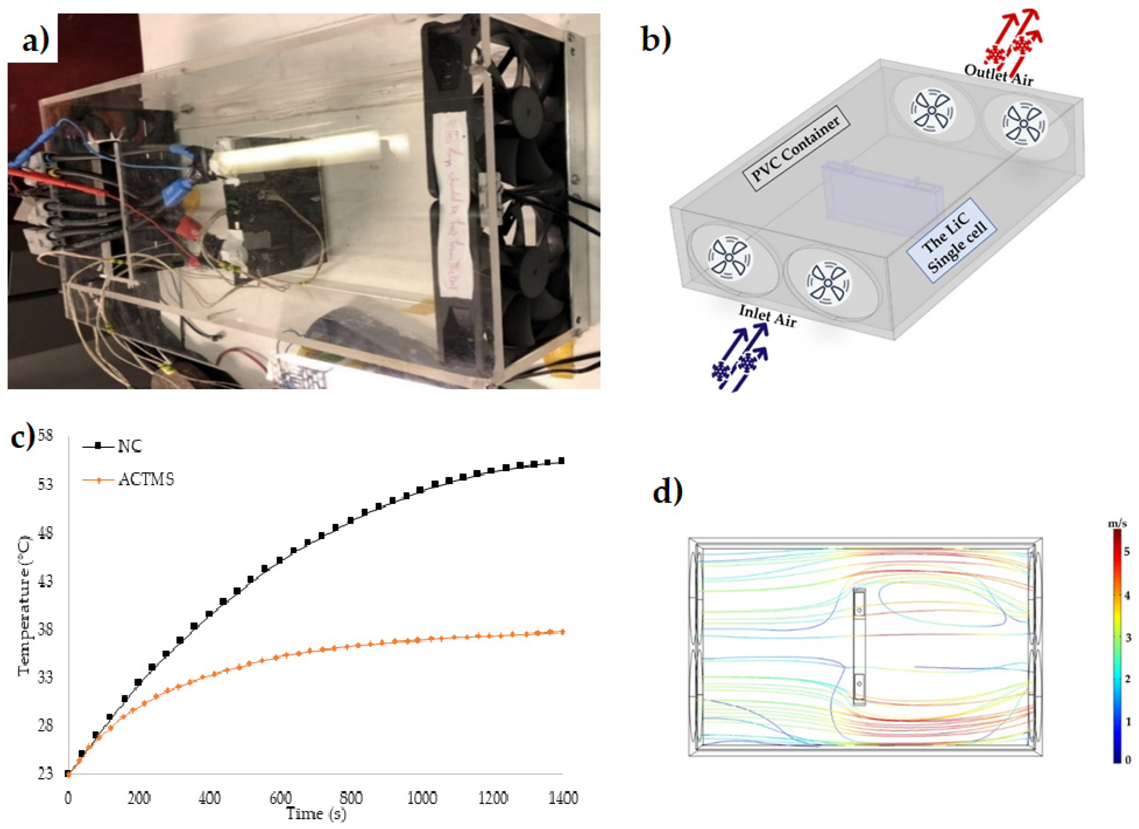
Figure 4.
(a) The experimental test bench of the air-cooled system for the LiC module; (b) the temperature evolution of 10 thermocouples on different positions of the module; (c) the temperature distribution of the module in the most optimal case study [18].
Figure 4.
(a) The experimental test bench of the air-cooled system for the LiC module; (b) the temperature evolution of 10 thermocouples on different positions of the module; (c) the temperature distribution of the module in the most optimal case study [18].

Figure 5.
Test setup of the liquid cooling system for LiC cell [27].
Figure 5.
Test setup of the liquid cooling system for LiC cell [27].

Figure 6.
Temperature distribution of the liquid based TMS for LiCs [28].
Figure 6.
Temperature distribution of the liquid based TMS for LiCs [28].

Figure 7.
Optimal liquid based TMS solutions for LiCs [28].
Figure 7.
Optimal liquid based TMS solutions for LiCs [28].
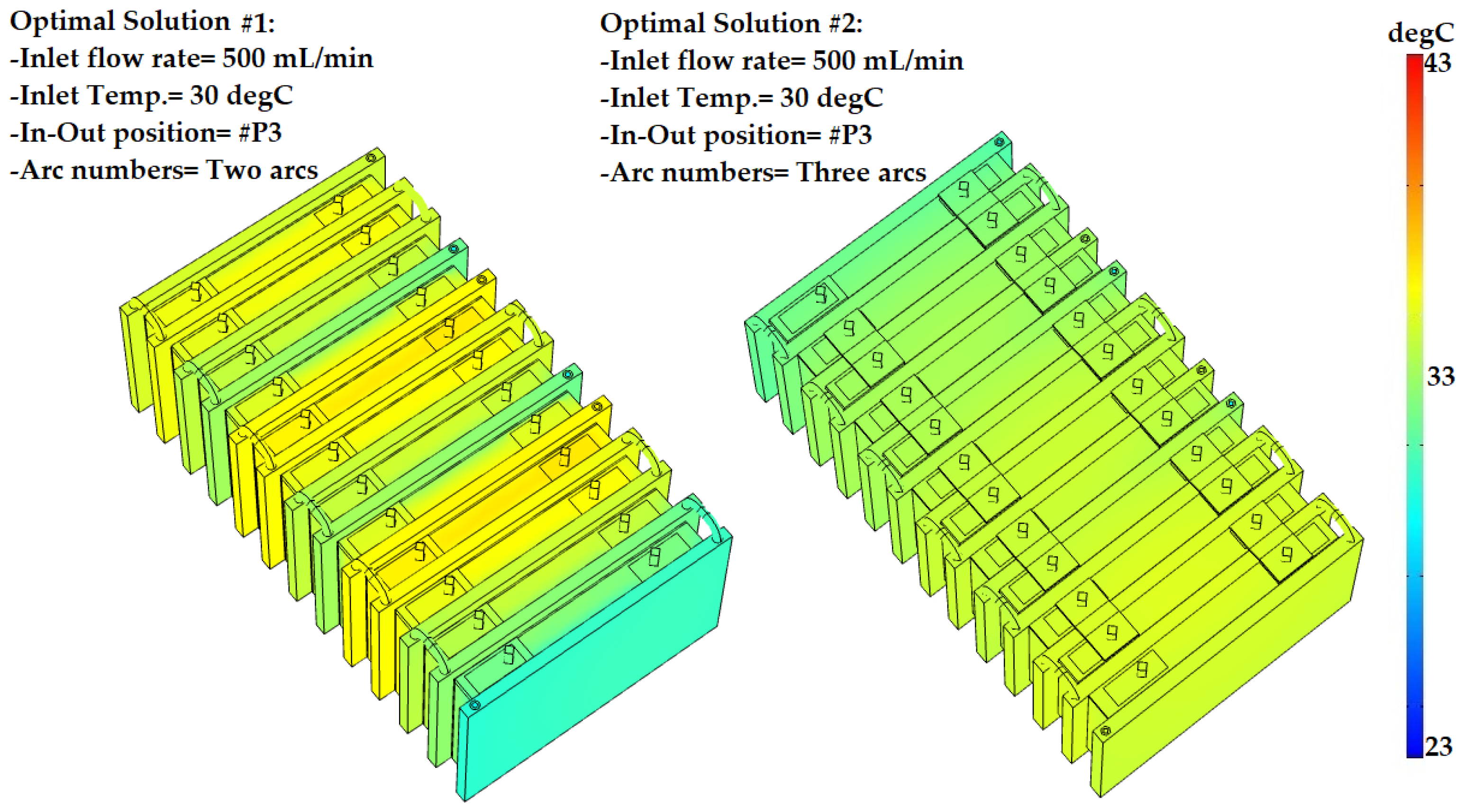
Figure 8.
(a) Experimental test bench of the heat sink cooling system (HSCS) for the LiC cell; (b) 3D model and mesh generation of the system; (c) temperature evolution of the heat sink cooling system (HSCS) compared with the natural convection (NC) [34].
Figure 8.
(a) Experimental test bench of the heat sink cooling system (HSCS) for the LiC cell; (b) 3D model and mesh generation of the system; (c) temperature evolution of the heat sink cooling system (HSCS) compared with the natural convection (NC) [34].

Figure 9.
The PCMs working principle: absorbing the thermal energy, storing it during phase change (solid to liquid), and releasing the absorbed heat.
Figure 9.
The PCMs working principle: absorbing the thermal energy, storing it during phase change (solid to liquid), and releasing the absorbed heat.
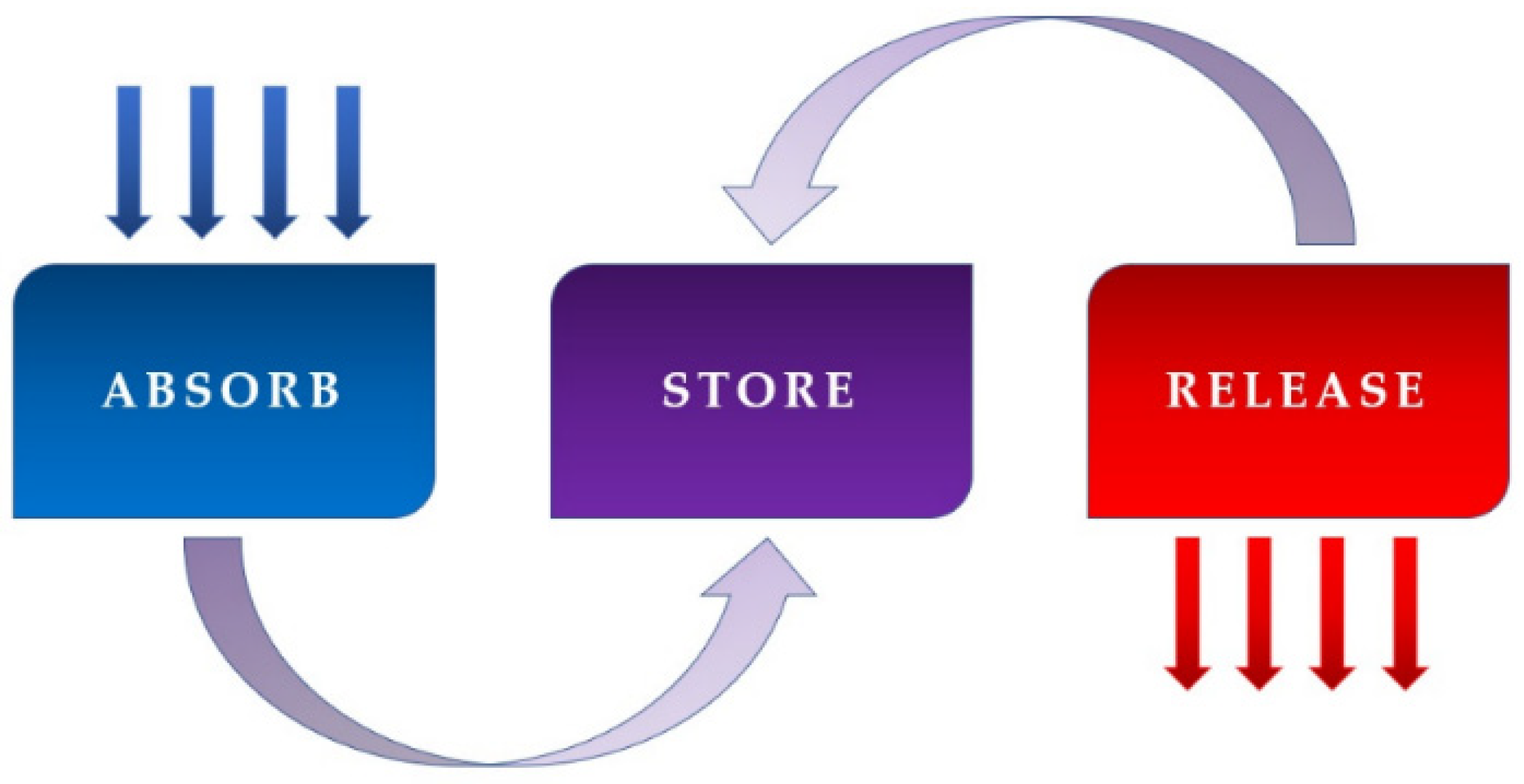
Figure 10.
(a) Simulation result for the pure PCM; (b) experimental result for the pure PCM taken by the thermal camera; (c) simulation result for the PCM-Al; (d) experimental result for the PCM-Al taken by the thermal camera [46].
Figure 10.
(a) Simulation result for the pure PCM; (b) experimental result for the pure PCM taken by the thermal camera; (c) simulation result for the PCM-Al; (d) experimental result for the PCM-Al taken by the thermal camera [46].
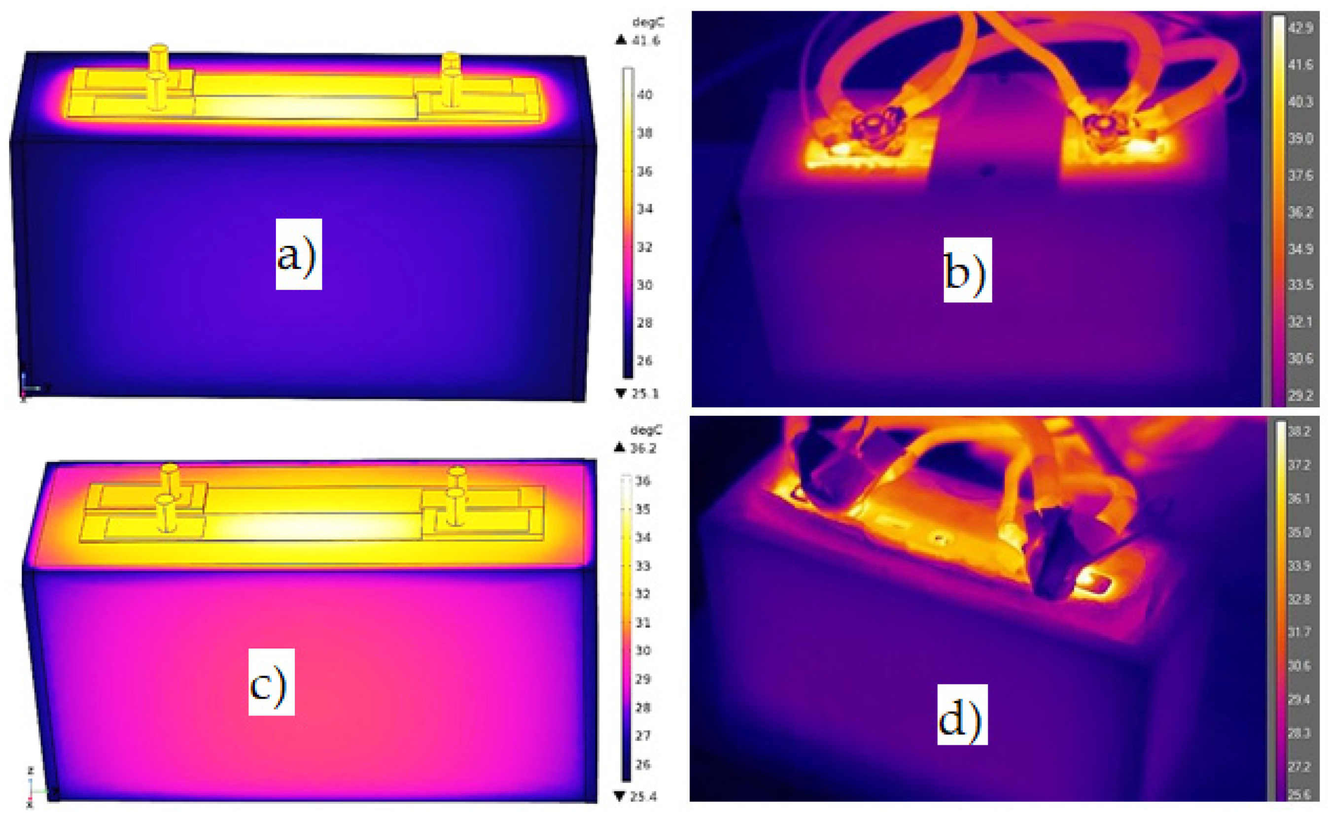
Figure 11.
(a) Experimental test bench of the PCM-Al mesh grid; (b) the results of three case studies including no-PCM, pure PCM, and PCM-Al [47].
Figure 11.
(a) Experimental test bench of the PCM-Al mesh grid; (b) the results of three case studies including no-PCM, pure PCM, and PCM-Al [47].
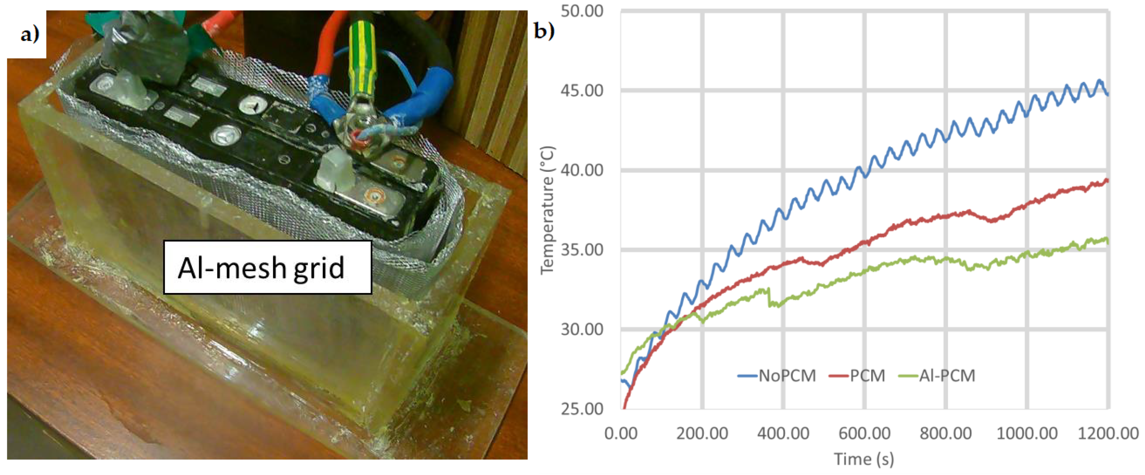
Figure 12.
The experimental results taken by the thermal camera (left) and the numerical simulation by COMSOL Multiphysics [66].
Figure 12.
The experimental results taken by the thermal camera (left) and the numerical simulation by COMSOL Multiphysics [66].
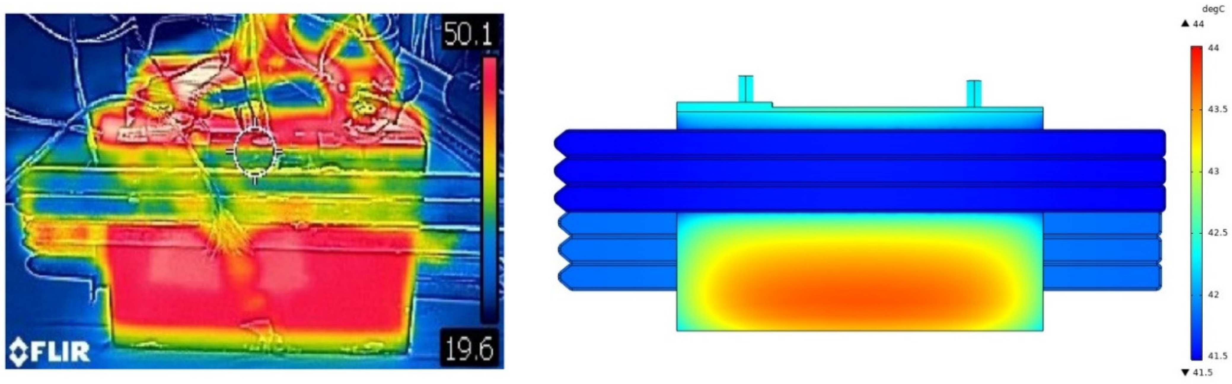
Figure 13.
(a) Thermal images of the hybrid PCM-heat pipe TMS for the LiC 2300 F cell; (b) top view of the cell considering the temperature distribution; (c) phase change regions from the liquid phase to the solid phase; (d) experimental setup of the system from solid phase to the liquid phase [48].
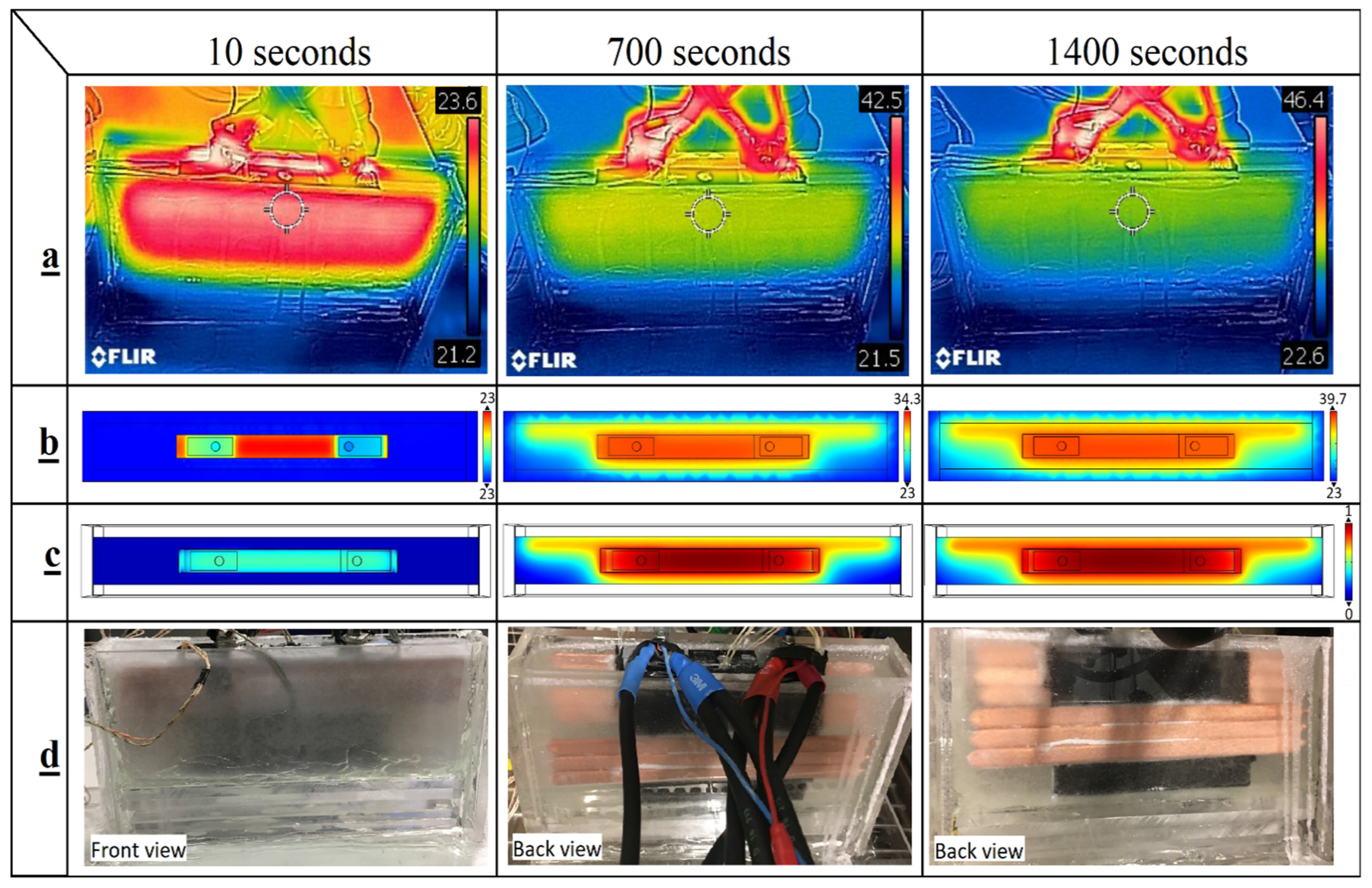
Figure 14.
The experimental test bench of the hybrid PCM-heat sink passive-passive TMS [41].
Figure 14.
The experimental test bench of the hybrid PCM-heat sink passive-passive TMS [41].

Figure 15.
The PCM solidification, the simulation results of the temperature evolution, and liquid fraction of the PCM at a 23 °C discharge process.
Figure 15.
The PCM solidification, the simulation results of the temperature evolution, and liquid fraction of the PCM at a 23 °C discharge process.
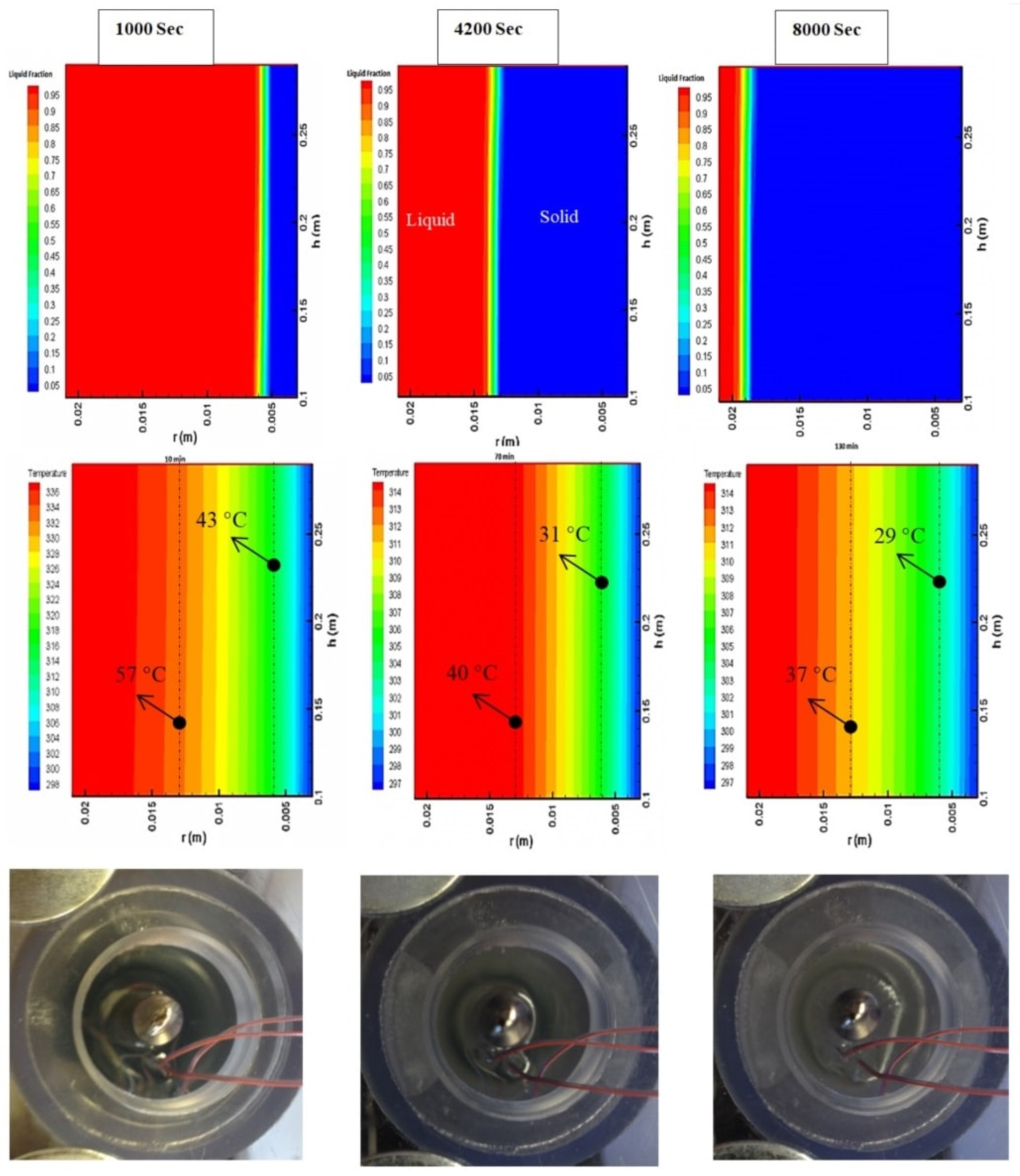
Figure 16.
Thermal performance of various scenarios for high power LTO cell: (a) Al mesh; (b) copper mesh; (c) phase change materials (PCM); and (d) hybrid PCM-graphite [89].
Figure 16.
Thermal performance of various scenarios for high power LTO cell: (a) Al mesh; (b) copper mesh; (c) phase change materials (PCM); and (d) hybrid PCM-graphite [89].

Figure 17.
The mesh generation and various domain of the hybrid liquid cooled-PCM TMS for a module of LiC [41].
Figure 17.
The mesh generation and various domain of the hybrid liquid cooled-PCM TMS for a module of LiC [41].

Figure 18.
The experimental test setup of the hybrid TMS including an air-cooling system and a large extruded heat sink [90].
Figure 18.
The experimental test setup of the hybrid TMS including an air-cooling system and a large extruded heat sink [90].

Figure 19.
(a) The LTO battery with the position of the K-type thermocouples; (b) the thermal image picture; (c) temperature evolution under 8C discharge rate [91].
Figure 19.
(a) The LTO battery with the position of the K-type thermocouples; (b) the thermal image picture; (c) temperature evolution under 8C discharge rate [91].

Figure 20.
The temperature distribution for cells 1 to 30 under 4C rate during 700 s: (a) during charging; (b) during discharging [92].
Figure 20.
The temperature distribution for cells 1 to 30 under 4C rate during 700 s: (a) during charging; (b) during discharging [92].

Figure 21.
Comparison of various systems for LiCs in high power applications; NC: natural convection, ACTMS: air cooled TMS, LCTMS: liquid cooled TMS, hybrid AC-LC: hybrid air cooling combined with a liquid cooling system [41].
Figure 21.
Comparison of various systems for LiCs in high power applications; NC: natural convection, ACTMS: air cooled TMS, LCTMS: liquid cooled TMS, hybrid AC-LC: hybrid air cooling combined with a liquid cooling system [41].
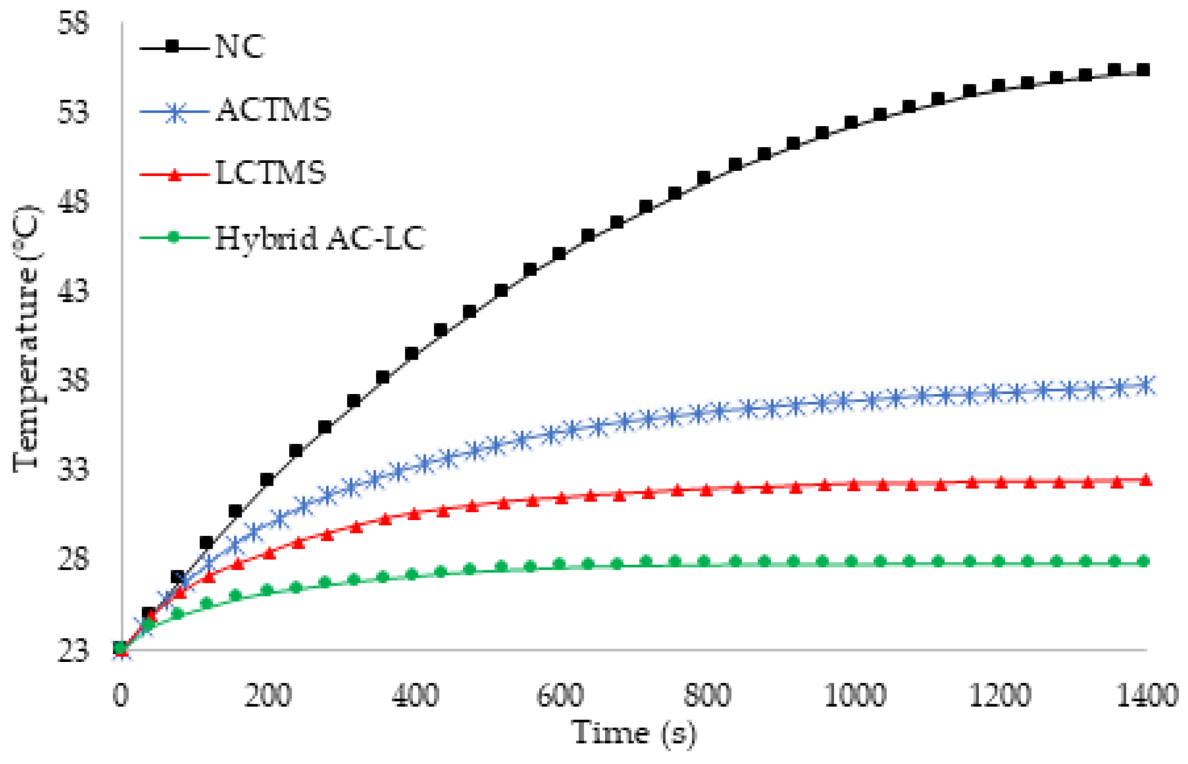
Table 3.
Temperature comparison of the LiC for different scenarios.
| Scenario | Tmax | Improvement |
|---|---|---|
| Natural convection (NC) | 55.3 °C | (Base system) |
| Heat sink cooling system | 44.8 °C | 18.9% |
| Heat pipe cooling system | 45.5 °C | 17.7% |
| Phase change materials (PCM) | 40.8 °C | 26.2% |
| Hybrid PCM-heat pipe | 35.8 °C | 35.2% |
| Hybrid PCM-heat sink | 34.1 °C | 38.3% |
Publisher’s Note: MDPI stays neutral with regard to jurisdictional claims in published maps and institutional affiliations. |
© 2022 by the authors. Licensee MDPI, Basel, Switzerland. This article is an open access article distributed under the terms and conditions of the Creative Commons Attribution (CC BY) license (https://creativecommons.org/licenses/by/4.0/).
Share and Cite
MDPI and ACS Style
Karimi, D.; Behi, H.; Van Mierlo, J.; Berecibar, M. Advanced Thermal Management Systems for High-Power Lithium-Ion Capacitors: A Comprehensive Review. Designs 2022, 6, 53. https://doi.org/10.3390/designs6030053
AMA Style
Karimi D, Behi H, Van Mierlo J, Berecibar M. Advanced Thermal Management Systems for High-Power Lithium-Ion Capacitors: A Comprehensive Review. Designs. 2022; 6(3):53. https://doi.org/10.3390/designs6030053
Chicago/Turabian StyleKarimi, Danial, Hamidreza Behi, Joeri Van Mierlo, and Maitane Berecibar. 2022. "Advanced Thermal Management Systems for High-Power Lithium-Ion Capacitors: A Comprehensive Review" Designs 6, no. 3: 53. https://doi.org/10.3390/designs6030053