
Utilizing Industrial By-Products for Sustainable Three-Dimensional-Printed Infrastructure Applications: A Comprehensive Review †

Department of Civil and Architectural Engineering and Mechanics, University of Arizona, 1209 E. 2nd St.Tucson, AZ 85721, USA
*
Author to whom correspondence should be addressed.
†
This paper was presented at the 5th International Conference on Transportation Infrastructures (V ICTI), Lima, Peru, 10–13 August 2022. It has been selected for publication in this journal.
Infrastructures 2023, 8(10), 140; https://doi.org/10.3390/infrastructures8100140
Submission received: 13 August 2023
/
Revised: 5 September 2023
/
Accepted: 20 September 2023
/
Published: 4 October 2023
(This article belongs to the Special Issue Selected Papers from the 5th International Conference on Transportation Infrastructures Conference)
Abstract
:Industrial secondary products (e.g., fly ash, blast furnace slag, and silica fume) have found extensive application as alternative construction materials in conventional manufacturing methods to reduce carbon emissions due to cement usage and solve the waste management problem. To date, additive manufacturing or 3D printing has been massively developed for every material, including cement-based materials. Some possibilities have arisen to incorporate industrial wastes in cement mixtures in 3D printing applications. However, a comprehensive study about fly ash (FA), ground granulated blast-furnace slag (GGBFS), and silica fume (SF) usage in 3D-printed materials needs to be conducted. This paper shows that some aspects of 3D printing, such as printability, buildability, and rheological properties, need to be considered, and waste materials affect these fresh mixture properties. Applying waste materials as supplementary cementitious materials also gives different mechanical properties and durability performances. Furthermore, the environmental and economic benefits of 3D-printed and conventional materials are compared. The results show that 3D printing methods can enhance the environmental and economic benefits while maintaining the performance of materials created using traditional methods. Studying industrial waste application in 3D printing has become a promising way to develop sustainable materials in this digitalization era.
1. Introduction
Waste production can affect the environment negatively. The expansion of modern industrial sectors has increased substantial amounts of waste globally. In addition, the issue of carbon dioxide emissions poses a noteworthy concern on a global scale. Portland cement is the most popular material in construction as a binding material. In 2013, Benhelal et al. reported that 0.9 tons of carbon dioxide is generated for every ton of cement production, and cement production contributes 5–7% of worldwide carbon dioxide emissions [1]. In 2022, the cement industry’s contribution to carbon dioxide emissions is still in the same percentage, at 7% [2]. The emission comes from different sources: (1) limestone calcination process (50% of total CO2), (2) burning coal fuels to generate combustion energy (40% of total CO2), and (3) transportation and electricity utilization during the manufacturing process [3]. As the demand for infrastructure keeps increasing, cement usage is also increasing. Hence, some alternative materials are needed to replace cement in construction applications. Many researchers have used waste materials to develop construction materials in infrastructure applications, such as pavements, footpaths, concrete, aggregate, bricks, and cement substitution [4,5,6,7,8,9]. Fly ash, blast-furnace slag, and silica fume are the predominant waste materials utilized in the construction sector as supplementary cementitious components.
Thomas classified fly ash and silica fume as pozzolan materials, while blast-furnace slag is a hydraulic material. Mixing fly ash in the concrete mixture has been carried out, ranging from 15 to 60% dosage levels [10]. Blast-furnace slag is also known as one of the alkali-activated materials that can fully replace cement [11]. Silica fume has a very high pozzolanic reactivity due to the silica content. The amount of silica in silica fume is usually higher than 85% [12]. It also has four roles in the concrete mixture, including to refine pore size, dense the matrix, react with free lime, and refine the cement and aggregate interfacial transition zone [13].
To improve sustainability in the construction industry, besides utilizing waste materials as supplementary cementitious materials, 3D printing is also considered to impact the environment positively. Many studies have discussed incorporating fly ash, blast-furnace slag, and silica fume in traditional concrete, but their usage still needs to be further explored in 3D printing applications. Automation in construction, like 3D concrete printing (3DCP), gives more benefits because it saves time and money. Some infrastructures have been designed and tested in previous trial projects, such as prestressed bridges [14,15] and several types of buildings [15]. A combination of waste material utilization and 3DCP operation can be a promising solution to greener construction materials. Some studies have shown successful stories about applying by-products and additives, such as mining waste, metakaolin, limestone calcined clay (LC2), and construction and demolition waste (CDW), in 3D printing mix [16,17,18,19,20,21,22]. Marczyk et al. showed that hybrid materials (concrete–geopolymer system) containing fly ash as a by-product material and metakaolin as an additive material precisely print an object [20]. Chen et al. presented that calcined clay and limestone additions enhance the buildability and accelerate the initial setting [22].
In this study, a review of common waste material utilization, like fly ash (FA), ground granulated blast-furnace slag (GGBFS), and silica fume (SF), for 3DCP application is conducted. This study only focuses on cement-based materials, such as cement paste, mortar, and concrete. A comparison of environmental and cost analysis between casting and 3D printing methods is considered. The prospective application of 3D printing in infrastructure is also presented to show the possibilities of 3DCP utilization in the future. The most recent literature published in 2022 and 2023 is prioritized to be reviewed.
2. Overview of Waste Materials
2.1. Fly Ash
Fly ash comes from the burning coal process in power plants as a by-product material and is placed in landfills [23]. Typically, the furnace generates coal ash in two forms: fly ash (75–85% of total coal ash) and bottom ash [24]. According to the American Coal Ash Association (ACAA), in 2021, 28 million tons of fly ash were generated, and 67.08% of total fly ash production was re-utilized in many sectors in the United States [25]. Generally, fly ash has two classes: class F and class C. Class F fly ash is called low-calcium fly ash, which is produced by burning bituminous coal. In contrast, class C fly ash originates from sub-bituminous coal ignition. The classification is characterized by its elevated calcium content [26]. Fly ash has a similar or finer particle size compared to cement and is predominantly spherical [12,26]. The morphological appearance of fly ash particles is spherical (hollow or solid) and irregular [27]. The hue of fly ash can range from pale to deep gray, typically associated with the type of coal that is burned and the amount of iron and unreacted carbon [12,27]. The typical physical and chemical attributes are tabulated in Table 1 and Table 2. The main chemical components are aluminum oxide, iron oxide, and silicon dioxide, which are presented as amorphous [27]. Silicon dioxide is the most dominant chemical component to generate a pozzolanic reaction. Fly ash has been successfully utilized in construction materials, either for cement or fine aggregate replacement [26,28]. According to the ASTM C618, the sum of oxides of silicon, aluminum, and iron must be at least 70% for class F fly ash and 50% for class C fly ash to have a pozzolanic reaction [29]. Fly ash is good in workability and reactivity, with 36% of the content being reactive silica and 88% of particles having a size under 45 µm [30].
2.2. Ground Granulated Blast-Furnace Slag
Slag or granulated ground blast-furnace slag (GGBFS) comes as a waste substance from the iron extraction process of iron ore in a blast furnace [23]. Globally, the amount of produced GGBFS is 530 million tons, and the re-utilization percentage of GGBFS is about 65% [38]. In 2019, 17 million tons of GGBFS was produced in the United States [39]. The characteristics of GGBFS were examined in a study by Pal et al., who divided slag into two types based on the basicity index: basic or acidic [40]. Basic GGBFS gives improved hydraulic activity because of alkaline activators [38]. For hydraulic activity assessment, the ratio between CaO and SiO2 is considered the simplest calculation method, and the value must exceed 1.0 [41]. The best value ranges from 1.3 to 1.4 [40]. Increasing the hydraulic activity involves raising the quantities of crystalline phases and chemical components, namely Al2O3, CaO, and MgO [40]. The hue of blast-furnace slag is usually off-white. The surface morphology of GGBFS is rough, and its fragments are angular [38]. The typical physical and chemical attributes of GGBFS are given in Table 3 and Table 4. GGBFS contains predominantly calcium, silica, and alumina in the forms of amorphous phase [38]. GGBFS has a larger specific surface area in terms of microscopic morphology due to the aggregation of smaller particles that create porous particles [34]. The larger surface area requires more materials to conceal GGBFS, thus decreasing the material paste’s flowability because of less lubrication material [38]. Particles that are finer than cement give better performance in strength development and water requirement [40]. Regarding hydration kinetics, GGBFS hydrates at a lower rate compared to Portland cement [41]. The addition of Portland cement increases the reaction rate. GGBFS is commonly used as cementitious materials, ranging from 20 to 80% of cement replacement level [42]. The standard of GGBFS usage as supplementary cementitious materials in mortar and concrete is regulated by the ASTM C989. Referring to the standard, there are three grades of GGBFS based on its strength: 80, 100, and 120 [43].
2.3. Silica Fume
Silica fume is a residual product resulting from silicon or ferrosilicon production by electric arc furnaces [23,46]. The appearance of silica fume is a glassy powder with a gray color [12]. A summary of silica fume characteristics was published by Gapinski and Scanlon in a technical paper, which classified silica fume as undensified and densified. Undensified silica fume is the first generated by-product without further processing, while densified one is undensified silica fume with additional processing. Undensified silica fume has a loose-fill density because of air voids before processing. Thus, densified silica fume has advantages in shipping costs due to packing efficiency while minimizing health risks due to dispersing fine particles [47,48]. In addition, densified silica fume tends to maintain its quality because there is no further agglomeration process after production [49]. Kang et al. have shown in ultra-high-performance fiber-reinforced concrete materials that both densified and undensified silica fumes perform similarly in terms of workability, strength, and hydration reaction [50]. The typical physical and chemical attributes of silica fume are given in Table 5 and Table 6. Silica fume contains 75% of silicon content, and 85–95% are non-crystalline silica [51]. Its pozzolanic reaction is relatively high because of the high silicon dioxide content. Silica fume has highly amorphous silicon dioxide and has extremely fine spherical particles [13]. Around 95% of its particles are smaller than 1 µm [12]. Besides high silicon dioxide, silica fume has a high surface area, affecting its reactivity [12]. Because of its high reactivity, in practice, silica fume is employed in small amounts, at 5–10%, to prevent bleeding and improve mechanical properties and durability [52,53]. Because of a very high surface area, concrete materials with silica fume require more water [51]. To achieve the desired workability, superplasticizers are needed for the mixture. The standard for silica fume addition in cementitious materials is published in the ASTM C1240 [46].
From the chemical compositions in Table 2, Table 4, and Table 6, a ternary diagram of supplementary cementitious materials is given in Figure 1. All waste materials show the same plots as provided in the literature [57]. According to the ternary diagram, the type of fly ash some authors used is class F.
3. Three-dimensional Printing in Construction
Three-dimensional printing or additive manufacturing is an advanced manufacturing method that converts a digital model to a real object by depositing material layers by layers. In construction applications, 3D printing is called 3D concrete printing (3DCP). With high-precision computer-aid automation techniques, 3DCP assembles materials into 3D structures by extruding a series of individual material filament stacks. It is recognized as an effective manufacturing process for sustainable development in the construction industry. Compared to traditional construction methods, 3D printing has some advantages and disadvantages, as listed in Table 7.
Because 3DCP does not require formwork, 3DCP mixture is expected to be continuously printable without failure. The printing quality parameters of 3DCP are commonly described as having four qualitative aspects: workability, pumpability, extrudability, and buildability. Those aspects relate to fundamental rheological properties include yield stress and plastic viscosity. Some of those aspects may have conflicts with each other. For example, high workability is needed during the pumping process before extrusion, but low workability is also needed after extrusion for better buildability of concrete. Hence, a mix design should be appropriately obtained depending on the application.
4. Fresh-State Performance
Three-dimensional printing tends to use more cement than the casting method because of the absence of formwork. Hence, the fresh-state properties have important roles in maintaining the aimed shape during the printing process and smoothly extruding the material mix through a nozzle [60]. Using excessive amounts of cement is avoided to make more sustainable materials. Waste materials have been commonly used as supplementary cementitious materials and fine aggregates, both in conventional and 3D printing. However, waste materials affect the fresh-state performance during the printing process. Some parameters to describe the fresh-state performance are rheology (yield stress and plastic viscosity), thixotropy, extrudability, and buildability.
Buswell et al. described other fresh-state parameters, including open time, pumpability, cycle time, and deformation. Open time is usually described in conventional concrete as concrete slump loss during hydration. In 3DCP, open time is the duration during which the concrete mix maintains the required viscosity and yield stress, influencing its extrudability or printability. Extrudability is the ability of a concrete mix to be extruded continuously through the printing nozzle. Cycle time denotes the time interval between extruding the current and subsequent filaments. This parameter affects the interlayer bond strength and cold jointing. Deformation under self-weight is associated with how the stacking filaments maintain the layer height under self-weight pressure [60]. Mandal et al. established certain rheological characteristics, including yield stress, plastic viscosity, thixotropy, structural build-up, shear thickening and thinning, flow resistance, and torque viscosity. However, yield stress and viscosity are the main rheological properties. Yield stress is the minimum stress to start or maintain the material flow and is also called static and dynamic yield stress, respectively. Once the flow moves, the resistance between the fluid and the surface appears in the form of plastic viscosity. Thixotropy is when the material stops flowing due to the loss of external shear force [61]. Chen et al. explained some basic requirements that are required to fulfill in 3D concrete printing: (1) sufficient dynamic yield stress (viscosity) to maintain the paste flow continuously, (2) high static yield stress to maintain buildability during the printing process, and (3) great thixotropy to ensure the paste flow smoothly [62].
Generally, the material flow increases by adding fly ash because its spherical shape has a ball-bearing effect [61]. Nodehi et al. examined how fly ash, GGBFS, and silica fume influence the fresh-sate properties. Fly ash addition decreases the yield stress of cement mixture, but sometimes, it increases the yield stress. The yield stress changes due to fly ash addition highly depend on the particle density, size, shape, and surface quality. For example, a very fine particle size leads to a high surface area, and fly ash can absorb more water and increase the water–binder ratio, thus increasing yield stress. In the end, it makes extrudability better. However, increasing the water–binder ratio eventually decreases the strength in the hardened state. GGBFS has been used as cement replacement by 10–35% without an alkaline activator and 100% with an activator in 3D concrete printing. In addition, GGBFS addition increases buildability and decreases the rheological parameters (e.g., yield stress and viscosity). However, extrudability is reduced if the replacement level by GGBFS is more than 30%. This evidence has been confirmed by Al-Noaimat et al., who showed that the negative effect of using GGBFS is decreased extrudability and flowability [63]. Silica fume generally increases yield stress and viscosity but sometimes has an opposite impact on both variables or on only viscosity. The different effects of silica fume appear depending on the surface properties, the replacement level, and the interaction between silica fume and other components [64]. Moreover, Yuan et al. evaluated fly ash and silica fume effects on cement paste. Fly ash decreases the thixotropic area of cement paste. It decreases the static yield stress, while silica fume shows the opposite effect in both the thixotropic area and static yield stress [65]. Yu et al. found that a higher level of slag content leads to a significant decrease in static yield stress because of the higher water absorption capability. Then, the amount of water within fresh materials is reduced. Ultimately, the static yield stress is not only influenced by the type of supplementary cementitious materials. The static yield stress of 3DCP paste is also influenced by particle morphology, particle-size distribution, zeta potential, and water–binder ratio [34].
5. Hardened-State Performance
The microstructure of concrete has excellent influences on mechanical properties and durability. Thus, the examination of porosity is a vital aspect to be considered. Mohan et al. evaluated the porosity in GGBFS-cement systems, and it was found that the porosity of cast specimens is 20% lower than 3D-printed ones. The volume of capillary pores in 3D-printed concrete is higher than in the cast ones because of the interconnected pores between the printing layers and the high moisture loss. According to X-ray μCT observations, the amount of open pores in the interlayer region is significantly higher than in bulk [66]. van den Heever et al. showed similar results for an FA-SF-cement system. The cast specimens have lower porosity (6.5%) than the 3D-printed specimens (10.3–10.8%) [67]. The porosity of 3D-printed concrete is more significant than cast concrete, and it can be reduced by adjusting the printing process, rheology, and environment [68].
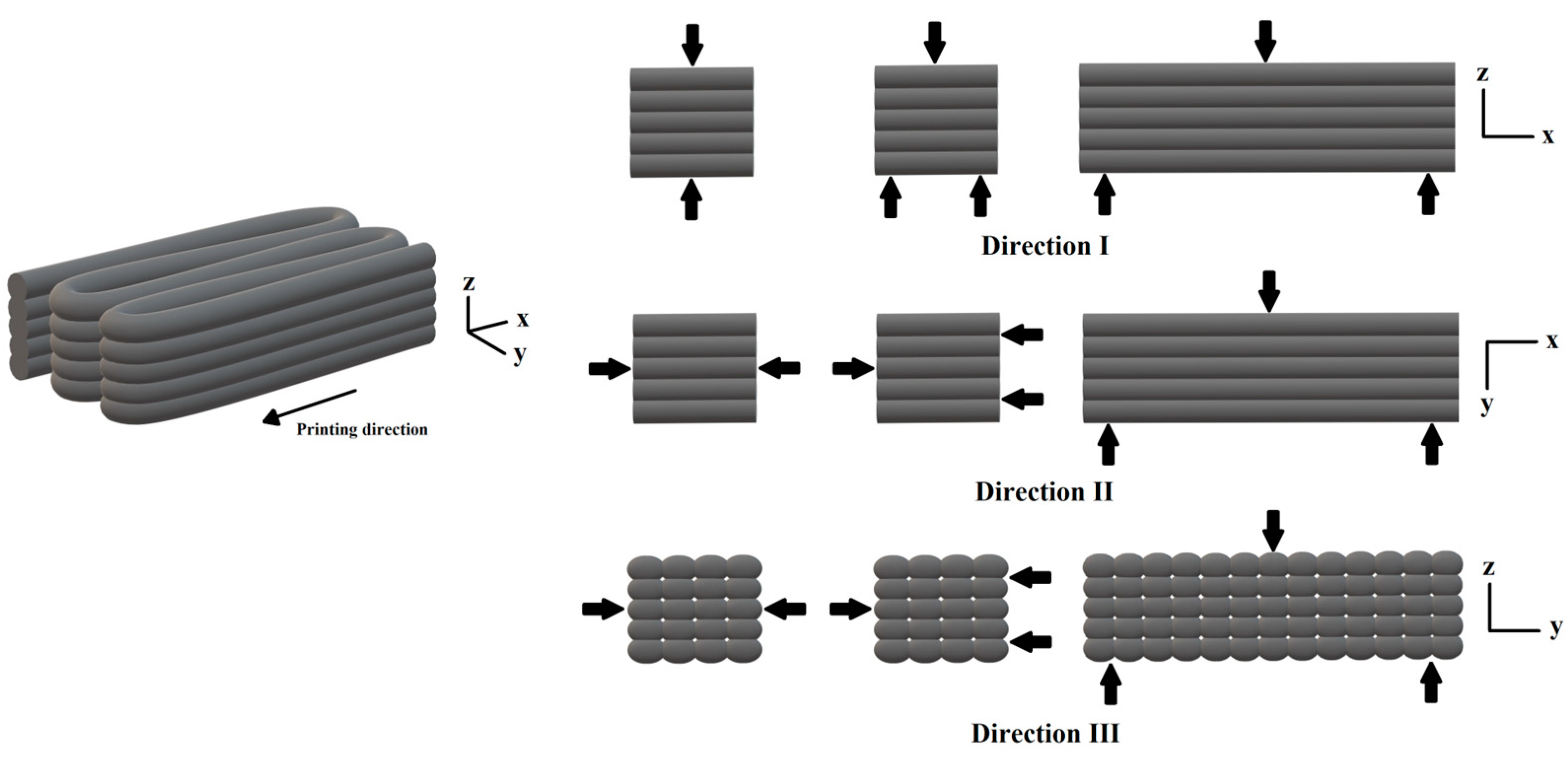
Porosity affects the mechanical properties of hardened materials. In FA-SF-cement samples, van den Heever et al. showed no significant difference in mechanical properties in the orthotropic orientation of 3D-printed samples. The elastic modulus values of the 3D-printed samples in the printing direction (longitudinal/x-direction, see Figure 2) and in the direction perpendicular to the printing direction (transversal/z-direction, see Figure 2) are 21.9 and 21.6 GPa, respectively. Meanwhile, the traditional sample gives a 26.7 GPa value. Regarding compressive strength, the 3D-printed samples show anisotropic properties. The compressive strengths in the longitudinal and transversal directions are 45.1 MPa and 38.2 MPa, respectively. Those values are lower than the cast sample’s compressive strength of 60.5 MPa. Three aspects give answers to why the mechanical properties can be different: (1) void shape and orientation, (2) porosity at the interlayer, and (3) orientation of the interlayer regions [67]. In 3D concrete printing (3DCP) applications, materials have anisotropic characteristics, which means the mechanical properties vary in three directions, x, y, and z, as shown in Figure 2. Chen et al. demonstrated that flexural and split strengths clearly show anisotropy in FA-GGBFS-cement systems. The weakest flexural strength and tensile strength occur in the direction III. The strengths in directions I and II have no significant difference. However, in this case, compressive strength has no prominent anisotropic characteristics. Regarding waste material incorporation, fly ash addition of up to 25% slightly enhances the compressive, flexural, and split tensile strengths of GGBFS concrete mixture compared to the one without fly ash. However, the mechanical strengths are reduced when the replacement levels are 50% and 75%. Increasing the ratio of FA/GGBFS decreases the mechanical strength because fly ash has a lower activation reactivity [69]. In terms of timing, Mohan et al. presented no significant change in open pores in the interlayer by increasing the time gap, which indicates no cold joint in the interlayer region. The range of time gap values was 90–155 min [66].
Porosity also influences the durability of hardened materials. Du et al. reported that the primary determinant impacting frost durability is the pore structure. Printed specimens have significant pore sizes and connectivity that cause the hydrostatic and osmotic pressures to be much lower than cast specimens during freeze–thaw loads [70,71]. Thus, the frost resistance in 3D-printed concrete is better than the traditional one. Another reason is that the moisture loss is high in 3DCP, so there is insufficient water to freeze [70]. It has also been proven by measuring the mass loss rate of these types of samples that the 3D-printed sample has a lower mass loss rate than the cast one [70]. The mass loss of a sample is calculated by subtracting the initial and final mass of the sample after several freeze–thaw cycles and normalizing the value by the initial mass of the sample. The mass of the 3D-printed sample is reduced due to an increase in porosity and surface degradation during multiple volumetric expansion of ice crystals [72]. Regarding chloride ion attack, cast specimens have better chloride ion attack resistance due to their uniform and less connected pores. In 3D-printed specimens, pores accumulate at the interface and make it easier for chloride ions to penetrate [70]. Waste materials are also important factors that relate to durability. Nodehi et al. reviewed that by-product materials influence permeability, porosity, and acid resistance. Fly ash gives great compaction and high sulfate and acid resistance. GGBFS also increases sulfate and acid resistance. Silica fume reduces porosity and increases compaction [73]. Decreasing porosity increases the mechanical properties and decreases the durability degradation.
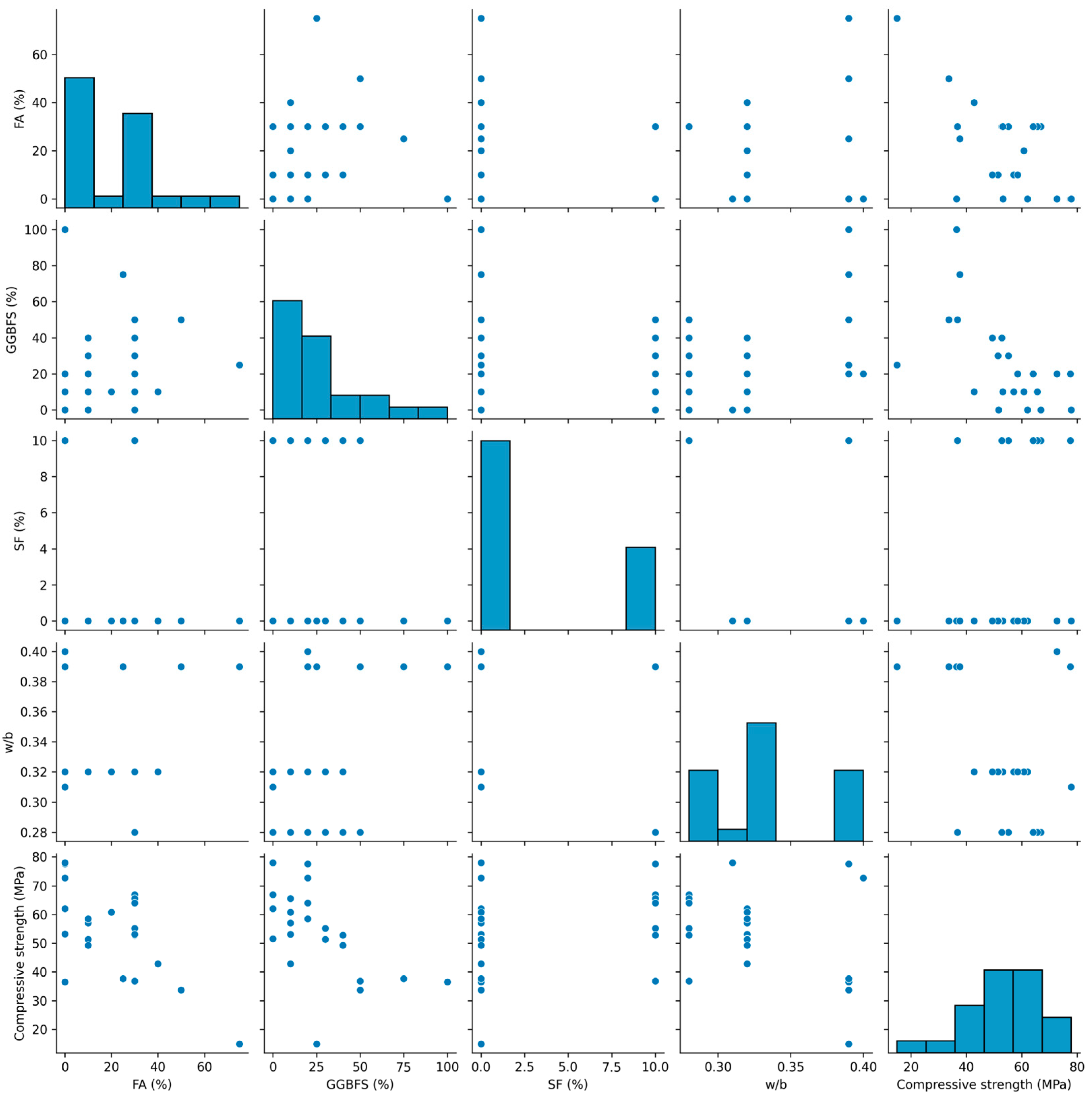
The 28-day compressive strengths of printed concrete with different compositions of waste materials are compiled in Table 8. Due to the anisotropic characteristics, the compressive strengths obtained from the literature show three strength components in the x, y, and z directions. The compressive strengths presented in Table 8 are the average values of compressive strengths in the three directions. From the table, pair plots are created and shown in Figure 3 to show the relationship between the variables in scatter plots and Figure 4 shows the heatmap scale—FA and GGBFS addition in 3D-printed concrete lowers the compressive strength. A higher water–binder ratio also decreases the compressive strength. However, due to pozzolanic activity, silica fume addition tends to increase the compressive strength slightly. The highest value of typical, required compressive strength for pavement is 5000 psi (34.47 MPa). All concrete systems in Table 8 fulfill the requirement, except for the mixtures with 50% FA + 50% GGBFS and 75% FA + 25% GGBFS.
Because of layer-by-layer deposition, 3D-printed concrete has another important mechanical property: interlayer bond strength. Ding et al. summarized the following factors as influencing this strength:
- Material compositions: binders, aggregates, admixtures, and fibers;
- Interfacial treatment: interfacial agent, interfacial shaping, and mechanical treatment;
- Printing parameters: interval time, filament shape, printing path, printing speed, and nozzle standoff distance;
- Printing environmental conditions: Temperature, humidity, and curing.
These factors influence the direct factors affecting interlayer bond strength, such as rheological behavior, pore structures, interface roughness, effective bonding area, hydration product, and surface moisture [75]. Due to the significance of the bond strength between the printed layers in 3D concrete printing, some methods to enhance this strength need to be investigated. Munemo et al. performed a new method by inducing thermo-hydrokinetics to increase the interlayer bond strength by 78% through steaming. The continuity in the interlayer region was also more significant than in the non-steamed samples [76]. He et al. conducted another method: making the filament interface a tooth-like shape. It was shown that the interlayer bond strength increased to 291% and the shear strength rose to 89% by designing the tooth shape with an angle of 45° [77].
6. Three-Dimensional Printing Applications
6.1. Pavement Repair
The method of 3DCP has excellent potential in maintaining infrastructures with automation processes. Yeon et al. developed an automated spall damage repair system using 3D printing. Rather than conducting repairs directly at the location, the suggested approach involved fabricating the concrete patch in the laboratory and subsequently installing it to the desired pavement surface. It showed that the method cut 2 h of road closure and potentially reduced economic losses from USD 140,000 to USD 1,700 due to road blockage. Regarding structural performance, two possible causes for the concrete patch to fail are compression stress due to vehicles’ weight and friction force due to vehicle deceleration. The latter is more likely to happen, and the shear stress needs to be increased. The shear stress resistance comes from friction between the concrete patch and the impaired surface and adhesive on the bottom of the concrete patch. The concrete patch’s bottom surface and the spalled concrete’s surface are likely rough and generate friction force. However, stability needs to be considered due to the irregular contour of these surfaces. In addition, the behaviors of adhesives with different thicknesses and temperatures must be tested in an actual application [78]. Vlachakis et al. established a similar idea in 2022 to design an advanced 3D-printed patch with self-sensing capability. Because the self-sensing system works according to the strain and is related to the mechanical properties of patches, creating a more uniform patch is essential. Hence, the filaments of the patches were fabricated vertically for the first layer and horizontally for the second layer [79].
Besides installing patches on damaged pavement surfaces, automated pavement crack repair using 3D printing equipment has been promoted by some studies in asphalt pavements [80,81,82,83]. However, autonomous damage repair can also be performed on concrete pavement. For instance, Liu et al. developed an automated pavement crack sealing by combining computer vision, a path planning algorithm, and 3D printing technology to detect and repair cracks on concrete pavement slabs. The proposed algorithm gives precise crack detection. Furthermore, a high contrast between crack and concrete specimen is the key to effective image capture. However, the cracks in that study were generated as simple cracks, and further study in real crack applications is essential. The excessive use of sealant is also a problem that must be solved to make the sealing process more stable [84]. Cantisani et al. studied the material selection of the filling mixture for pavement repair. The mixture comprised 100% recycled asphalt pavement and a recycling agent. The laboratory experiments showed that the mixture performs excellently in indirect tensile strength, Marshall stability, and particle loss. Asphalt-based materials can be applied on asphalt and concrete pavements [85].
6.2. Structural Elements
Most structural elements’ shape complexity is the reason for colossal formwork usage in construction. To reduce the number of formworks, 3D printing becomes a potential method to create complicated structural elements, such as shear keys and beams. Hua et al. conducted a design and experimental study of the shear key element using 3DCP. The results show that the cracking mechanism on the 3D-printed shear key specimens is similar to the precast shear key samples, in which the crack on the specimens starts propagating vertically. The presence of epoxy resin between the male and female parts solves the geometrical defects during fabrication and enhances the shear resistance significantly. Compared to the precast shear keys, the 3D-printed shear keys only have a 4.93% lower normalized shear strength [86]. Topology optimization is commonly applied when designing concrete beam structures by optimizing the problem objective in a large-scale structure. Vantyghem et al. designed a post-tensioned concrete girder following topology optimization. The results show that with the same flange size, total deflection, and overall depth as the optimized beam geometries, the material was saved up to 20%. The advantages of the proposed topology optimization are minimizing material consumption, no need for a particular framework, and autonomous manufacturing [87]. Sung and Andrawes invented a prestressed concrete bridge girder using shape memory alloy bars as the reinforcements. After optimization, the concrete volume was reduced by 28.5%, and the shape memory alloy reinforcements were placed on the bottom of the midspan and the top of the interior support. The optimized girder design satisfied the AASHTO LRFD stress limits at the initial, deck casting, and service stages [88].
Breseghello et al. developed a carbon-efficient beam named 3DLightBeam+ using computational work. According to the testing, the 3D-printed beam exhibited a greater flexural strength–weight ratio than other types of 3DCP beams. Compared to the full, porous grid, and infill-optimized beam, the ratio was greater by 200%, 120%, and 20%, respectively. The carbon footprint of this advanced beam was also evaluated. The carbon dioxide emission by considering the carbonation process was 30% less than the porous grid 3DCP beam and 60% less than the full 3DCP beam. Regarding computation, the workflow used in 3DLightBeam+ development gave a practical simulation approach that could be used for other shapes without increasing the computation time. The simulation work was also shown to be close to the experimental results, with a peak strength difference of 3% [89]. Another computational work-assisted project was also conducted by Dell’Endice et al. to design an unreinforced 3D concrete-printed masonry pedestrian arch bridge named Striatus. The material usage was decreased because the structure was reduced by 40% in the cross-section. In addition, the structure only exhibited a compression state, which means it does not need reinforcement bars and provides the possibility to recycle the printed materials [90]. Huang et al. built a sophisticated project using computer-assisted 3D concrete printing for the Shenzhen Baoan 3D Printing Park project. To generate complex patterns and construction algorithms, three different paving patterns were designed using space-filling and printing path generation methods. Three-dimensional printing helps this complex project to build an 836 sqm printed pavement area [91].
6.3. Building Design and Renovation
Three-dimensional printing is a great method to build a sophisticated building due to its high flexibility in making complex geometry, like contour crafting. One example of a 3D-printed building is a two-story public building for Dubai Municipality [59]. Gypsum-based mix was used to create wall structures with a height of 9.5 m and an area of 640 m2 using 3D printing [59]. Three-dimensional printing is also helpful in the building renovation process, allowing the operator to customize the parts and components, for example, the production and installation of precast concrete façade sections [92]. Because of the high complexity, 3D printing can improve product quality compared to conventional methods, and prevent post-installation problems (e.g., air and water leakages) [92]. In addition, a flying 3D printing robot that was inspired by builder creatures has been developed [93]. This idea supports the needs of building or infrastructure maintenance in remote locations.
7. Environmental and Economic Analysis
Life cycle assessment (LCA) is frequently employed to evaluate holistic environmental impact. Mohammad et al. employed LCA to assess the environmental benefits of using 3D printing for construction following the ISO 14040. Five environmental impact categories were used in the study and their definitions were as follows:
- Global Warming Potential (GWP): influence of emissions from greenhouse gases;
- Acidification Potential (AP): impact of acidic;
- Eutrophication Potential (EP): impact of nitrogen and phosphorus;
- Smog Formation Potential (SFP): ozone level;
- Fossil Fuel Depletion (FFD): energy generated from the earth.
In utilizing concrete materials with the conventional construction method, formwork usage contributes approximately 20% of the total EP, and it can be removed by applying the 3D printing method. In [94], formwork gives a negative value to GWP because it is made of timber. When the timber is a tree, it is considered to absorb carbon dioxide. However, other factors, such as manufacturing, transportation, and other processes, during its lifetime need to be considered. Generally, 3D-printed concrete without reinforcements has fewer negative impacts in all five categories. Conventional concrete emits 58.89 kg CO2eq of greenhouse gas, while 3D-printed concrete without any reinforcements emits 44.42–46.12 kg CO2eq. Thus, by employing 3D printing in making construction materials that use 184.42 kg of concrete, greenhouse gas emissions can be reduced by approximately 20% [94]. Liu et al. conducted a comparative LCA study to evaluate and compare the environmental impact of two sustainable production methods: (1) 3D-printed and conventional casting concrete and (2) different industrial wastes. The LCA was performed following the ISO 14040 series. The findings indicate that the environmental footprint of 3D-printed OPC-based concrete mix is reduced by incorporating waste materials, like fly ash and silica fume, to substitute cement. Furthermore, 3D printing is greener for manufacturing complex and non-repetitive concrete structures because special casting formwork is environmentally demanding [23].
As the usage of waste materials increases and the manufacturing process is automatic, economic benefits are also gained. Han et al. compared the fabrication cost between casting and 3D printing methods. The economic advantage can be achieved for complex structure construction. Materials and additives budgets are the main contributors to the high cost of 3D printing. The increasing electricity cost in 3D printing is significantly less than the costs of formwork and labor [95]. Mohan et al. also proved similar results in terms of construction cost. In 3D printing, the total material cost rises to 55% due to chemical admixture addition. Increasing the ratio of aggregate and binder can lower the cost, but it has negative consequences, such as high pumping pressure demand [66] and decreased material strength [96]. High pumping pressure needs high power, which might impact emissions.
8. Conclusions and Recommendations
This review shows that by-product materials like fly ash (FA), ground granulated blast-furnace slag (GGBFS), and silica fume (SF) can positively and negatively affect fresh- and hardened-state properties in 3D concrete printing. Regarding environmental impact, 3D printing is more beneficial than conventional one. The benefits can be improved, both in environmental and economic aspects, by replacing the binder with by-product materials. Three-dimensional printing is also promising for real applications in construction. For further research, some recommendations can be followed:
- Development of mechanical testing standard for 3D-printed concrete;
- Finding applicable methods to enhance the interlayer bond strength and decrease porosity at the interlayer regions;
- Further research about crack sealing mixture using waste materials that are suitable for certain pavements under different environmental conditions;
- Exploring other printable waste materials to minimize negative environmental impact and cost.
Author Contributions
Conceptualization, E.O.K. and H.-J.K.; writing—original draft preparation, E.O.K.; writing—review and editing, H.-J.K.; supervision, H.-J.K. All authors have read and agreed to the published version of the manuscript.
Funding
The support was provided by the Technology Research Initiative Fund/National Security System—Innovative Technology for the 4th Industrial Revolution—Advanced Manufacturing Project and the Improving Health Initiatives administered by the University of Arizona Office for Research, Innovation and Impact, funded under Proposition 301, the Arizona Sales Tax for Education Act, in 2000.
Data Availability Statement
Conflicts of Interest
The authors declare no conflict of interest.
References
- Benhelal, E.; Zahedi, G.; Shamsaei, E.; Bahadori, A. Global strategies and potentials to curb CO2 emissions in cement industry. J. Clean. Prod. 2013, 51, 142–161. [Google Scholar] [CrossRef]
- Korczak, K.; Kochański, M.; Skoczkowski, T. Mitigation options for decarbonization of the non-metallic minerals industry and their impacts on costs, energy consumption and GHG emissions in the EU—Systematic literature review. J. Clean. Prod. 2022, 358, 132006. [Google Scholar] [CrossRef]
- Supriya; Chaudhury, R.; Sharma, U.; Thapliyal, P.C.; Singh, L.P. Low-CO2 emission strategies to achieve net zero target in cement sector. J. Clean. Prod. 2023, 417, 137466. [Google Scholar] [CrossRef]
- Abbas, S.; Saleem, M.A.; Kazmi, S.M.S.; Munir, M.J. Production of sustainable clay bricks using waste fly ash: Mechanical and durability properties. J. Build. Eng. 2017, 14, 7–14. [Google Scholar] [CrossRef]
- Ganjian, E.; Jalull, G.; Sadeghi-Pouya, H. Using waste materials and by-products to produce concrete paving blocks. Constr. Build. Mater. 2015, 77, 270–275. [Google Scholar] [CrossRef]
- Günçan, N.F. Using waste concrete as aggregate. Cem. Concr. Res. 1995, 25, 1385–1390. [Google Scholar]
- Kim, Y.J.; Choi, Y.W. Utilization of waste concrete powder as a substitution material for cement. Constr. Build. Mater. 2012, 30, 500–504. [Google Scholar] [CrossRef]
- Mohammadinia, A.; Wong, Y.C.; Arulrajah, A.; Horpibulsuk, S. Strength evaluation of utilizing recycled plastic waste and recycled crushed glass in concrete footpaths. Constr. Build. Mater. 2019, 197, 489–496. [Google Scholar] [CrossRef]
- Zhao, Z.; Xiao, F.; Amirkhanian, S. Recent applications of waste solid materials in pavement engineering. Waste Manag 2020, 108, 78–105. [Google Scholar] [CrossRef]
- Thomas, M. Optimizing the Use of Fly Ash in Concrete; Portland Cement Association: Skokie, IL, USA, 2007; Volume 5420. [Google Scholar]
- Amran, M.; Murali, G.; Khalid, N.H.A.; Fediuk, R.; Ozbakkaloglu, T.; Lee, Y.H.; Haruna, S.; Lee, Y.Y. Slag uses in making an ecofriendly and sustainable concrete: A review. Constr. Build. Mater. 2021, 272, 121942. [Google Scholar] [CrossRef]
- Soomro, M.; Tam, V.W.; Evangelista, A.C.J. Industrial and agro-waste materials for use in recycled concrete. In Recycled Concrete; Elsevier: Cambridge, UK, 2023; pp. 47–117. [Google Scholar]
- Siddique, R. Utilization of silica fume in concrete: Review of hardened properties. Resour. Conserv. Recycl. 2011, 55, 923–932. [Google Scholar] [CrossRef]
- Salet, T.A.; Ahmed, Z.Y.; Bos, F.P.; Laagland, H.L. Design of a 3D printed concrete bridge by testing. Virtual Phys. Prototyp. 2018, 13, 222–236. [Google Scholar] [CrossRef]
- Buswell, R.A.; Bos, F.P.; Silva, W.R.L.d.; Hack, N.; Kloft, H.; Lowke, D.; Freund, N.; Fromm, A.; Dini, E.; Wangler, T. Digital fabrication with cement-based materials: Process classification and case studies. In Digital Fabrication with Cement-Based Materials: State-of-the-Art Report of the RILEM TC 276-DFC; Springer: Cham, Switzerland, 2022; pp. 11–48. [Google Scholar]
- Ma, G.; Li, Z.; Wang, L. Printable properties of cementitious material containing copper tailings for extrusion based 3D printing. Constr. Build. Mater. 2018, 162, 613–627. [Google Scholar] [CrossRef]
- Zhao, Z.; Cao, S.; Yilmaz, E. Effect of layer thickness on the flexural property and microstructure of 3D-printed rhomboid polymer-reinforced cemented tailing composites. Int. J. Miner. Metall. Mater. 2022, 30, 236–249. [Google Scholar] [CrossRef]
- Sun, B.; Zeng, Q.; Wang, D.; Zhao, W. Sustainable 3D printed mortar with CO2 pretreated recycled fine aggregates. Cem. Concr. Compos. 2022, 134, 104800. [Google Scholar] [CrossRef]
- Ilcan, H.; Sahin, O.; Kul, A.; Yildirim, G.; Sahmaran, M. Rheological properties and compressive strength of construction and demolition waste-based geopolymer mortars for 3D-Printing. Constr. Build. Mater. 2022, 328, 127114. [Google Scholar] [CrossRef]
- Marczyk, J.; Ziejewska, C.; Gadek, S.; Korniejenko, K.; Lach, M.; Gora, M.; Kurek, I.; Dogan-Saglamtimur, N.; Hebda, M.; Szechynska-Hebda, M. Hybrid Materials Based on Fly Ash, Metakaolin, and Cement for 3D Printing. Materials 2021, 14, 6874. [Google Scholar] [CrossRef] [PubMed]
- Ibrahim, K.A.; van Zijl, G.P.A.G.; Babafemi, A.J. Influence of limestone calcined clay cement on properties of 3D printed concrete for sustainable construction. J. Build. Eng. 2023, 69, 106186. [Google Scholar] [CrossRef]
- Chen, Y.; He, S.; Zhang, Y.; Wan, Z.; Çopuroğlu, O.; Schlangen, E. 3D printing of calcined clay-limestone-based cementitious materials. Cem. Concr. Res. 2021, 149, 106553. [Google Scholar] [CrossRef]
- Liu, S.; Lu, B.; Li, H.; Pan, Z.; Jiang, J.; Qian, S. A comparative study on environmental performance of 3D printing and conventional casting of concrete products with industrial wastes. Chemosphere 2022, 298, 134310. [Google Scholar] [CrossRef]
- Joshi, R.C.; Lohita, R. Fly Ash in Concrete: Production, Properties and Uses; CRC Press: Boca Raton, FL, USA, 1997; Volume 2. [Google Scholar]
- American Coal Ash Association. Coal Combustion Products Production & Use Reports; American Coal Ash Association: Sandy, UT, USA, 2021. [Google Scholar]
- Papadakis, V.G. Effect of fly ash on Portland cement systems: Part I. Low-calcium fly ash. Cem. Concr. Res. 1999, 29, 1727–1736. [Google Scholar] [CrossRef]
- Mathapati, M.; Amate, K.; Durga Prasad, C.; Jayavardhana, M.L.; Hemanth Raju, T. A review on fly ash utilization. Mater. Today Proc. 2022, 50, 1535–1540. [Google Scholar] [CrossRef]
- Siddique, R. Effect of fine aggregate replacement with Class F fly ash on the mechanical properties of concrete. Cem. Concr. Res. 2003, 33, 539–547. [Google Scholar] [CrossRef]
- ASTM C618; Standard Specification for Coal Fly Ash and Raw or Calcined Natural Pozzolan for Use in Concrete. ASTM International: West Conshohocken, PA, USA, 2017.
- Korniejenko, K.; Kejzlar, P.; Louda, P. The Influence of the Material Structure on the Mechanical Properties of Geopolymer Composites Reinforced with Short Fibers Obtained with Additive Technologies. Int. J. Mol. Sci. 2022, 23, 2023. [Google Scholar] [CrossRef]
- Papadakis, V.G. Effect of fly ash on Portland cement systems: Part II. High-calcium fly ash. Cem. Concr. Res. 2000, 30, 1647–1654. [Google Scholar] [CrossRef]
- Li, G.; Zhao, X. Properties of concrete incorporating fly ash and ground granulated blast-furnace slag. Cem. Concr. Compos. 2003, 25, 293–299. [Google Scholar] [CrossRef]
- Xu, Z.; Zhang, D.; Li, H.; Sun, X.; Zhao, K.; Wang, Y. Effect of FA and GGBFS on compressive strength, rheology, and printing properties of cement-based 3D printing material. Constr. Build. Mater. 2022, 339, 127685. [Google Scholar] [CrossRef]
- Yu, Q.; Zhu, B.; Li, X.; Meng, L.; Cai, J.; Zhang, Y.; Pan, J. Investigation of the rheological and mechanical properties of 3D printed eco-friendly concrete with steel slag. J. Build. Eng. 2023, 72, 106621. [Google Scholar] [CrossRef]
- Rafieizonooz, M.; Khankhaje, E.; Rezania, S. Assessment of environmental and chemical properties of coal ashes including fly ash and bottom ash, and coal ash concrete. J. Build. Eng. 2022, 49, 104040. [Google Scholar] [CrossRef]
- Aslam, F.; Zaid, O.; Althoey, F.; Alyami, S.H.; Qaidi, S.M.; de Prado Gil, J.; Martínez-García, R. Evaluating the influence of fly ash and waste glass on the characteristics of coconut fibers reinforced concrete. Struct. Concr. 2023, 24, 2440–2459. [Google Scholar] [CrossRef]
- Gopalakrishna, B.; Dinakar, P. Mix design development of fly ash-GGBS based recycled aggregate geopolymer concrete. J. Build. Eng. 2023, 63, 105551. [Google Scholar] [CrossRef]
- Ahmad, J.; Kontoleon, K.J.; Majdi, A.; Naqash, M.T.; Deifalla, A.F.; Ben Kahla, N.; Isleem, H.F.; Qaidi, S.M.A. A Comprehensive Review on the Ground Granulated Blast Furnace Slag (GGBS) in Concrete Production. Sustainability 2022, 14, 8783. [Google Scholar] [CrossRef]
- Curry, K.C. Iron and Steel Slag; U.S. Geological Survey: Reston, VA, USA, 2020.
- Pal, S.; Mukherjee, A.; Pathak, S. Investigation of hydraulic activity of ground granulated blast furnace slag in concrete. Cem. Concr. Res. 2003, 33, 1481–1486. [Google Scholar] [CrossRef]
- Özbay, E.; Erdemir, M.; Durmuş, H.İ. Utilization and efficiency of ground granulated blast furnace slag on concrete properties—A review. Constr. Build. Mater. 2016, 105, 423–434. [Google Scholar] [CrossRef]
- Matthes, W.; Vollpracht, A.; Villagrán, Y.; Kamali-Bernard, S.; Hooton, D.; Gruyaert, E.; Soutsos, M.; De Belie, N. Ground granulated blast-furnace slag. In Properties of Fresh and Hardened Concrete Containing Supplementary Cementitious Materials: State-of-the-Art Report of the RILEM Technical Committee 238-SCM, Working Group 4; Springer: Cham, Switzerland, 2018; pp. 1–53. [Google Scholar]
- ASTM C989a; Standard Specification for Slag Cement for Use in Concrete and Mortars. ASTM International: West Conshohocken, PA, USA, 2022.
- Singh, R.P.; Vanapalli, K.R.; Cheela, V.R.S.; Peddireddy, S.R.; Sharma, H.B.; Mohanty, B. Fly ash, GGBS, and silica fume based geopolymer concrete with recycled aggregates: Properties and environmental impacts. Constr. Build. Mater. 2023, 378, 131168. [Google Scholar] [CrossRef]
- Kanavaris, F.; Soutsos, M.; Chen, J.-F. Enabling sustainable rapid construction with high volume GGBS concrete through elevated temperature curing and maturity testing. J. Build. Eng. 2023, 63, 105434. [Google Scholar] [CrossRef]
- ASTM C1240; Standard Specification for Silica Fume Used in Cementitious Mixtures. ASTM International: West Conshohocken, PA, USA, 2005.
- Gapinski, G.M.; Scanlon, J. Silica Fume. Norchem Technical Papers and Articles. 2006. Available online: https://www.norchem.com/pdf/technical-papers-articles-gapinksi-scanlon.pdf (accessed on 4 August 2023).
- Pedro, D.; de Brito, J.; Evangelista, L. Evaluation of high-performance concrete with recycled aggregates: Use of densified silica fume as cement replacement. Constr. Build. Mater. 2017, 147, 803–814. [Google Scholar] [CrossRef]
- Aldred, J.M.; Holland, T.C.; Morgan, D.R.; Roy, D.M.; Bury, M.A.; Hooton, R.D.; Olek, J.; Scali, M.J.; Detwiler, R.J.; Jaber, T.M. Guide for the Use of Silica Fume in Concrete; ACI–American Concrete Institute–Committee: Farmington Hills, MI, USA, 2006; p. 234. [Google Scholar]
- Kang, S.H.; Hong, S.G.; Moon, J. Performance Comparison between Densified and Undensified Silica Fume in Ultra-High Performance Fiber-Reinforced Concrete. Materials 2020, 13, 3901. [Google Scholar] [CrossRef] [PubMed]
- Mehta, A.; Ashish, D.K. Silica fume and waste glass in cement concrete production: A review. J. Build. Eng. 2020, 29, 100888. [Google Scholar] [CrossRef]
- Rossen, J.E.; Lothenbach, B.; Scrivener, K.L. Composition of C–S–H in pastes with increasing levels of silica fume addition. Cem. Concr. Res. 2015, 75, 14–22. [Google Scholar] [CrossRef]
- Holland, T.C. Silica Fume User’s Manual; Silica Fume Association: Lovettsville, VA, USA, 2005. [Google Scholar]
- Dotto, J.; De Abreu, A.; Dal Molin, D.; Müller, I. Influence of silica fume addition on concretes physical properties and on corrosion behaviour of reinforcement bars. Cem. Concr. Compos. 2004, 26, 31–39. [Google Scholar] [CrossRef]
- Li, B.; Gao, A.; Li, Y.; Xiao, H.; Chen, N.; Xia, D.; Wang, S.; Li, C. Effect of silica fume content on the mechanical strengths, compressive stress–strain behavior and microstructures of geopolymeric recycled aggregate concrete. Constr. Build. Mater. 2023, 384, 131417. [Google Scholar] [CrossRef]
- Kathirvel, P.; Murali, G. Effect of using available GGBFS, silica fume, quartz powder and steel fibres on the fracture behavior of sustainable reactive powder concrete. Constr. Build. Mater. 2023, 375, 130997. [Google Scholar] [CrossRef]
- Lothenbach, B.; Scrivener, K.; Hooton, R. Supplementary cementitious materials. Cem. Concr. Res. 2011, 41, 1244–1256. [Google Scholar] [CrossRef]
- El-Sayegh, S.; Romdhane, L.; Manjikian, S. A critical review of 3D printing in construction: Benefits, challenges, and risks. Arch. Civ. Mech. Eng. 2020, 20, 34. [Google Scholar] [CrossRef]
- Mierzwiński, D.; Łach, M.; Gądek, S.; Lin, W.-T.; Tran, D.H.; Korniejenko, K. A brief overview of the use of additive manufacturing of con-create materials in construction. Acta Innov. 2023, 48, 22–37. [Google Scholar] [CrossRef]
- Buswell, R.A.; Leal de Silva, W.R.; Jones, S.Z.; Dirrenberger, J. 3D printing using concrete extrusion: A roadmap for research. Cem. Concr. Res. 2018, 112, 37–49. [Google Scholar] [CrossRef]
- Mandal, R.; Panda, S.K.; Nayak, S. Rheology of Concrete: Critical Review, recent Advancements, and future prospectives. Constr. Build. Mater. 2023, 392, 132007. [Google Scholar] [CrossRef]
- Chen, M.; Yang, L.; Zheng, Y.; Huang, Y.; Li, L.; Zhao, P.; Wang, S.; Lu, L.; Cheng, X. Yield stress and thixotropy control of 3D-printed calcium sulfoaluminate cement composites with metakaolin related to structural build-up. Constr. Build. Mater. 2020, 252, 119090. [Google Scholar] [CrossRef]
- Al-Noaimat, Y.A.; Ghaffar, S.H.; Chougan, M.; Al-Kheetan, M.J. A review of 3D printing low-carbon concrete with one-part geopolymer: Engineering, environmental and economic feasibility. Case Stud. Constr. Mater. 2023, 18, e01818. [Google Scholar] [CrossRef]
- Nodehi, M.; Ozbakkaloglu, T.; Gholampour, A. Effect of supplementary cementitious materials on properties of 3D printed conventional and alkali-activated concrete: A review. Autom. Constr. 2022, 138, 104215. [Google Scholar] [CrossRef]
- Yuan, Q.; Zhou, D.; Li, B.; Huang, H.; Shi, C. Effect of mineral admixtures on the structural build-up of cement paste. Constr. Build. Mater. 2018, 160, 117–126. [Google Scholar] [CrossRef]
- Mohan, M.K.; Rahul, A.V.; van Dam, B.; Zeidan, T.; De Schutter, G.; Van Tittelboom, K. Performance criteria, environmental impact and cost assessment for 3D printable concrete mixtures. Resour. Conserv. Recycl. 2022, 181, 106255. [Google Scholar] [CrossRef]
- van den Heever, M.; du Plessis, A.; Kruger, J.; van Zijl, G. Evaluating the effects of porosity on the mechanical properties of extrusion-based 3D printed concrete. Cem. Concr. Res. 2022, 153, 106695. [Google Scholar] [CrossRef]
- Bhushan Jindal, B.; Jangra, P. 3D Printed Concrete: A comprehensive review of raw material’s properties, synthesis, performance, and potential field applications. Constr. Build. Mater. 2023, 387, 131614. [Google Scholar] [CrossRef]
- Chen, Y.; Jia, L.; Liu, C.; Zhang, Z.; Ma, L.; Chen, C.; Banthia, N.; Zhang, Y. Mechanical anisotropy evolution of 3D-printed alkali-activated materials with different GGBFS/FA combinations. J. Build. Eng. 2022, 50, 104126. [Google Scholar] [CrossRef]
- Du, L.; Zhou, J.; Lai, J.; Wu, K.; Yin, X.; He, Y. Effect of pore structure on durability and mechanical performance of 3D printed concrete. Constr. Build. Mater. 2023, 400, 132581. [Google Scholar] [CrossRef]
- Zhang, Y.; Zhang, Y.; Yang, L.; Liu, G.; Chen, Y.; Yu, S.; Du, H. Hardened properties and durability of large-scale 3D printed cement-based materials. Mater. Struct. 2021, 54, 54. [Google Scholar] [CrossRef]
- Min, Y.; Wu, J.; Li, B.; Zhang, M.; Zhang, J. Experimental study of freeze–thaw resistance of a one-part geopolymer paste. Case Stud. Constr. Mater. 2022, 17, e01269. [Google Scholar] [CrossRef]
- Nodehi, M.; Aguayo, F.; Nodehi, S.E.; Gholampour, A.; Ozbakkaloglu, T.; Gencel, O. Durability properties of 3D printed concrete (3DPC). Autom. Constr. 2022, 142, 104479. [Google Scholar] [CrossRef]
- Hojati, M.; Li, Z.; Memari, A.M.; Park, K.; Zahabi, M.; Nazarian, S.; Duarte, J.P.; Radlińska, A. 3D-printable quaternary cementitious materials towards sustainable development: Mixture design and mechanical properties. Results Eng. 2022, 13, 100341. [Google Scholar] [CrossRef]
- Ding, T.; Xiao, J.; Mechtcherine, V. Microstructure and mechanical properties of interlayer regions in extrusion-based 3D printed concrete: A critical review. Cem. Concr. Compos. 2023, 141, 105154. [Google Scholar] [CrossRef]
- Munemo, R.; Kruger, J.; van Zijl, G.P.A.G. Improving interlayer bond in 3D printed concrete through induced thermo-hydrokinetics. Constr. Build. Mater. 2023, 393, 132121. [Google Scholar] [CrossRef]
- He, L.; Li, H.; Chow, W.T.; Zeng, B.; Qian, Y. Increasing the interlayer strength of 3D printed concrete with tooth-like interface: An experimental and theoretical investigation. Mater. Des. 2022, 223, 111117. [Google Scholar] [CrossRef]
- Yeon, J.; Kang, J.; Yan, W. Spall damage repair using 3D printing technology. Autom. Constr. 2018, 89, 266–274. [Google Scholar] [CrossRef]
- Vlachakis, C.; McAlorum, J.; Perry, M. 3D printed cement-based repairs and strain sensors. Autom. Constr. 2022, 137, 104202. [Google Scholar] [CrossRef]
- Gong, F.; Cheng, X.; Fang, B.; Cheng, C.; Liu, Y.; You, Z. Prospect of 3D printing technologies in maintenance of asphalt pavement cracks and potholes. J. Clean. Prod. 2023, 397, 136551. [Google Scholar] [CrossRef]
- Gong, F.; Cheng, X.; Chen, Y.; Liu, Y.; You, Z. 3D printed rubber modified asphalt as sustainable material in pavement maintenance. Constr. Build. Mater. 2022, 354, 129160. [Google Scholar] [CrossRef]
- Gong, F.; Cheng, X.; Wang, Q.; Chen, Y.; You, Z.; Liu, Y. A Review on the Application of 3D Printing Technology in Pavement Maintenance. Sustainability 2023, 15, 6237. [Google Scholar] [CrossRef]
- Awuah, F.K.; Garcia-Hernández, A. Machine-filling of cracks in asphalt concrete. Autom. Constr. 2022, 141, 104463. [Google Scholar] [CrossRef]
- Liu, J.; Yang, X.; Wang, X.; Yam, J.W. A laboratory prototype of automatic pavement crack sealing based on a modified 3D printer. Int. J. Pavement Eng. 2021, 23, 2969–2980. [Google Scholar] [CrossRef]
- Cantisani, G.; D’Andrea, A.; Di Mascio, P.; Moretti, L.; Fiore, N.; Petrelli, M.; Polidori, C.; Venturini, L. Materials study to implement a 3D printer system to repair road pavement potholes. Transp. Res. Procedia 2023, 69, 91–98. [Google Scholar] [CrossRef]
- Hua, T.; Lin, A.; Poh, W.J.D.; Charlene; Wong, D.H.A.; Zhang, H.; Chan, Y.Z.; Liu, W.; Zhao, L. 3D-printed concrete shear keys: Design and experimental study. Dev. Built Environ. 2023, 15, 100180. [Google Scholar] [CrossRef]
- Vantyghem, G.; De Corte, W.; Shakour, E.; Amir, O. 3D printing of a post-tensioned concrete girder designed by topology optimization. Autom. Constr. 2020, 112, 103084. [Google Scholar] [CrossRef]
- Sung, M.; Andrawes, B. Topology Optimization of Continuous Precast Prestressed Concrete Bridge Girders Using Shape Memory Alloys. J. Struct. Eng. 2023, 149, 04023051. [Google Scholar] [CrossRef]
- Breseghello, L.; Hajikarimian, H.; Jørgensen, H.B.; Naboni, R. 3DLightBeam+. Design, simulation, and testing of carbon-efficient reinforced 3D concrete printed beams. Eng. Struct. 2023, 292, 116511. [Google Scholar] [CrossRef]
- Dell’Endice, A.; Bouten, S.; Van Mele, T.; Block, P. Structural design and engineering of Striatus, an unreinforced 3D-concrete-printed masonry arch bridge. Eng. Struct. 2023, 292, 116534. [Google Scholar] [CrossRef]
- Huang, S.; Xu, W.; Hu, H. Space-filling and print path generation methods for large-area 3D concrete printing pavements. Archit. Intell. 2023, 2, 13. [Google Scholar] [CrossRef]
- Chougan, M.; Al-Kheetan, M.J.; Ghaffar, S.H. Additive Manufacturing and the Construction Industry. In Disrupting Buildings: Digitalisation and the Transformation of Deep Renovation; Springer International Publishing: Cham, Switzerland, 2023; pp. 97–109. [Google Scholar]
- Dams, B.; Chen, B.; Shepherd, P.; Ball, R.J. Development of Cementitious Mortars for Aerial Additive Manufacturing. Appl. Sci. 2023, 13, 641. [Google Scholar] [CrossRef]
- Mohammad, M.; Masad, E.; Al-Ghamdi, S.G. 3D concrete printing sustainability: A comparative life cycle assessment of four construction method scenarios. Buildings 2020, 10, 245. [Google Scholar] [CrossRef]
- Han, Y.; Yang, Z.; Ding, T.; Xiao, J. Environmental and economic assessment on 3D printed buildings with recycled concrete. J. Clean. Prod. 2021, 278, 123884. [Google Scholar] [CrossRef]
- Khatib, J.M. Properties of concrete incorporating fine recycled aggregate. Cem. Concr. Res. 2005, 35, 763–769. [Google Scholar] [CrossRef]
Figure 1.
Ternary diagram of waste materials. FA: fly ash; GGBFS: ground granulated blast-furnace slag; SF: silica fume.
Figure 1.
Ternary diagram of waste materials. FA: fly ash; GGBFS: ground granulated blast-furnace slag; SF: silica fume.

Figure 2.
Three-dimensional-printed concrete testing samples before and after cutting in terms of compressive strength, split tensile strength, and flexural strength [69].
Figure 2.
Three-dimensional-printed concrete testing samples before and after cutting in terms of compressive strength, split tensile strength, and flexural strength [69].

Figure 3.
Pair plots of 3D-printed concrete with different compositions and water–binder ratio. FA: fly ash; GGBFS: ground granulated blast-furnace slag; SF: silica fume; w/b: water–binder ratio.
Figure 3.
Pair plots of 3D-printed concrete with different compositions and water–binder ratio. FA: fly ash; GGBFS: ground granulated blast-furnace slag; SF: silica fume; w/b: water–binder ratio.

Figure 4.
Correlation heatmap of 3D-printed concrete. FA: fly ash; GGBFS: ground granulated blast-furnace slag; SF: silica fume; w/b: water–binder ratio.
Figure 4.
Correlation heatmap of 3D-printed concrete. FA: fly ash; GGBFS: ground granulated blast-furnace slag; SF: silica fume; w/b: water–binder ratio.


| Physical Properties | Materials | |
|---|---|---|
| Cement | Fly Ash | |
| Specific gravity (g/cm3) | 3.05 | 2.43 |
| Blaine-specific surface (m2/kg) | 392 | 565 |
| Particle mean diameter (μm) | 14.0 | 12.6–22.9 |
| Density (kg/m3) | 3130 | 2250–2660 |
Table 2.
Chemical compositions of fly ash.
| Reference | Components (wt%) | |||||||||||
|---|---|---|---|---|---|---|---|---|---|---|---|---|
| Al2O3 | CaO | Fe2O3 | K2O | MgO | MnO | Na2O | P2O5 | SiO2 | SO3 | TiO2 | Al2O3 + Fe2O3 + SiO2 | |
| [33] | 29.05 | 4.87 | 5.78 | 2.56 | 0.90 | - | - | - | 52.17 | - | 1.42 | 87.00 |
| [34] | 37.00 | 6.05 | 5.56 | 0.71 | 0.88 | 0.06 | 0.75 | 0.69 | 41.12 | 1.08 | 1.38 | 83.68 |
| [35] | 23.80 | 10.70 | 7.40 | 1.40 | 1.50 | 0.12 | 2.10 | 1.16 | 47.60 | 0.73 | 2.92 | 78.80 |
| [36] | 26.80 | 3.10 | 7.30 | 1.50 | 2.30 | - | 0.10 | - | 58.70 | 0.20 | - | 92.80 |
| [37] | 27.28 | 3.25 | 9.28 | 2.82 | 1.52 | - | 1.12 | - | 50.13 | - | - | 86.69 |
| Physical Properties | Materials | |
|---|---|---|
| Cement | Ground Granulated Blast-Furnace Slag | |
| Specific gravity (g/cm3) | 3.05 | 2.79–2.90 |
| Blaine-specific surface (m2/kg) | 392 | 599 |
| Particle mean diameter (μm) | 14.0 | 9.42 |
| Density (kg/m3) | 3130 | 1200–1300 |
Table 4.
Chemical compositions of ground granulated blast-furnace slag.
| Reference | Components (wt%) | |||||||||||
|---|---|---|---|---|---|---|---|---|---|---|---|---|
| Al2O3 | CaO | Fe2O3 | K2O | MgO | MnO | Na2O | P2O5 | SiO2 | SO3 | TiO2 | CaO/SiO2 | |
| [33] | 14.58 | 41.91 | 0.33 | 0.61 | 7.88 | 0.53 | 0.27 | - | 29.75 | 1.74 | 1.66 | 1.41 |
| [34] | 8.09 | 38.77 | 19.14 | 0.13 | 4.25 | 2.00 | 0.31 | 1.82 | 18.93 | 2.62 | 0.82 | 2.05 |
| [37] | 15.63 | 40.15 | 1.56 | 0.52 | 6.54 | - | 0.21 | - | 35.32 | - | - | 1.14 |
| [44] | 12.40 | 43.17 | 0.37 | 0.18 | 5.80 | 0.58 | 0.91 | 0.59 | 31.65 | 0.98 | 0.40 | 1.36 |
| [45] | 11.23 | 43.72 | 0.36 | 0.93 | 6.94 | - | 1.01 | - | 29.38 | 1.76 | - | 1.49 |
| Physical Properties | Materials | |
|---|---|---|
| Cement | Silica Fume | |
| Specific gravity (g/cm3) | 3.12 | 2.22 |
| BET-specific surface (m2/kg) | 1.22 | 13.86 |
| Particle mean diameter (μm) | 14.0 | 0.50 |
| Undensified density (kg/m3) | - | 130–430 |
| Densified density (kg/m3) | 3130 | 480–720 |
Table 6.
Chemical compositions of silica fume.
| Reference | Components (wt%) | |||||||||||
|---|---|---|---|---|---|---|---|---|---|---|---|---|
| Al2O3 | CaO | Fe2O3 | K2O | MgO | MnO | Na2O | P2O5 | SiO2 | SO3 | TiO2 | Al2O3 + Fe2O3 + SiO2 | |
| [34] | 0.78 | 1.05 | 0.92 | 0.67 | 0.59 | 0.42 | 0.59 | 0.23 | 92.76 | 0.53 | 0.12 | 94.46 |
| [44] | 0.19 | 0.40 | 0.95 | 0.62 | 0.17 | 0.73 | 0.00 | 1.10 | 93.74 | 0.34 | 0.48 | 94.88 |
| [54] | 0.12 | 0.30 | 0.15 | 1.51 | 0.73 | - | 0.46 | - | 90.21 | 0.01 | - | 90.48 |
| [55] | 0.31 | 0.12 | 0.07 | - | 0.11 | - | - | - | 96.65 | 1.21 | - | 97.03 |
| [56] | 0.29 | 0.29 | 0.03 | - | 0.11 | - | - | - | 98.70 | 1.82 | - | 99.02 |
| Advantages | Disadvantages |
|---|---|
| Reduce time and cost | Complicated mix design to fulfill the printability, buildability, and open time requirements |
| Able to build complex geometry with high accuracy | Directional dependency (e.g., anisotropic material properties) |
| Shorter supply chain | Risk of cybersecurity |
| Enhance productivity | Low structural integrity |
| Sustainable materials and structures | High initial cost (e.g., equipment, transportation) |
| Less waste and redundant materials | Require new labor skills |
| Fewer formwork | Need routine inspection during the printing process |
| Safer workplace | Regulations and codes are still unavailable |
| Reduce number of labors | High project management risks |
Table 8.
Compressive strength of 3D-printed concrete at 28 days.
| Reference | Replacement Level (%) | w/b 4 | Compressive Strength (MPa) | ||
|---|---|---|---|---|---|
| FA 1 | GGBFS 2 | SF 3 | |||
| [69] | 0 | 100 | 0 | 0.39 | 36.48 |
| 25 | 75 | 0 | 37.64 | ||
| 50 | 50 | 0 | 33.68 | ||
| 75 | 25 | 0 | 14.90 | ||
| [34] | 30 | 0 | 10 | 0.28 | 66.92 |
| 30 | 10 | 10 | 65.63 | ||
| 30 | 20 | 10 | 64.06 | ||
| 30 | 30 | 10 | 55.18 | ||
| 30 | 40 | 10 | 52.77 | ||
| 30 | 50 | 10 | 36.77 | ||
| [33] | 0 | 0 | 0 | 0.32 | 62.08 |
| 0 | 10 | 0 | 53.27 | ||
| 10 | 10 | 0 | 57.10 | ||
| 20 | 10 | 0 | 60.80 | ||
| 30 | 10 | 0 | 53.14 | ||
| 40 | 10 | 0 | 42.79 | ||
| 10 | 0 | 0 | 51.61 | ||
| 10 | 20 | 0 | 58.50 | ||
| 10 | 30 | 0 | 51.35 | ||
| 10 | 40 | 0 | 49.31 | ||
| [74] | 0 | 20 | 0 | 0.40 | 72.76 |
| 0 | 20 | 10 | 0.39 | 77.52 | |
| 0 | 0 | 0 | 0.31 | 77.93 | |
1 FA: fly ash; 2 GGBFS: ground granulated blast-furnace slag; 3 SF: silica fume; 4 w/b: water–binder ratio.
Disclaimer/Publisher’s Note: The statements, opinions and data contained in all publications are solely those of the individual author(s) and contributor(s) and not of MDPI and/or the editor(s). MDPI and/or the editor(s) disclaim responsibility for any injury to people or property resulting from any ideas, methods, instructions or products referred to in the content. |
© 2023 by the authors. Licensee MDPI, Basel, Switzerland. This article is an open access article distributed under the terms and conditions of the Creative Commons Attribution (CC BY) license (https://creativecommons.org/licenses/by/4.0/).
Share and Cite
MDPI and ACS Style
Kurniati, E.O.; Kim, H.-J. Utilizing Industrial By-Products for Sustainable Three-Dimensional-Printed Infrastructure Applications: A Comprehensive Review. Infrastructures 2023, 8, 140. https://doi.org/10.3390/infrastructures8100140
AMA Style
Kurniati EO, Kim H-J. Utilizing Industrial By-Products for Sustainable Three-Dimensional-Printed Infrastructure Applications: A Comprehensive Review. Infrastructures. 2023; 8(10):140. https://doi.org/10.3390/infrastructures8100140
Chicago/Turabian StyleKurniati, Eka Oktavia, and Hee-Jeong Kim. 2023. "Utilizing Industrial By-Products for Sustainable Three-Dimensional-Printed Infrastructure Applications: A Comprehensive Review" Infrastructures 8, no. 10: 140. https://doi.org/10.3390/infrastructures8100140