Tuning the Anti-Phase Mode Sensitivity to Vibrations of a MEMS Gyroscope †
by
 ,
,
Pierre Janioud
1,2,*, 
Alexandra Koumela
1,2,
Christophe Poulain
1,2,
Patrice Rey
1,2,
Audrey Berthelot
1,2,
Panagiota Morfouli
1 and
Guillaume Jourdan
1,2 1
University Grenoble Alpes, Grenoble F-38000, France
2
CEA, LETI, MINATEC Campus, Grenoble F-38054, France
*
Author to whom correspondence should be addressed.
†
Presented at the Eurosensors 2017 Conference, Paris, France, 3–6 September 2017.
Proceedings 2017, 1(4), 355; https://doi.org/10.3390/proceedings1040355
Published: 8 August 2017
(This article belongs to the Proceedings of Proceedings of Eurosensors 2017, Paris, France, 3–6 September 2017)
Abstract
:This paper proposes a stiffness correction method to improve the resilience to vibration of a dual-mass MEMS gyroscope with a particular focus near the resonance frequency of the anti-phase drive mode (fDa), i.e., its operational mode. Because of its balanced shape, this operating mode is ideally insensitive to vibrations. However, fabrication imperfections generates a residual sensitivity to parasitic vibrations that can disturb normal operation of the sensor. This work shows that the application of a DC voltage (Vtr) at the drive actuation electrode enables to decrease this sensitivity by a factor of at least 30 because of the stiffness tuning of the dual-mass structure. Experiments are performed to confirm this assumption and an efficient stiffness correction method is proposed to improve device operation.
1. Introduction
The increasing use of Coriolis Vibratory Gyroscopes (CVG), combined with stringent specifications in various applications from military and automotive domains, requires to considerably enhance their robustness and their resilience to external mechanical vibrations. Commonly used to sense angular rate or angle, CVG consist in a tuning fork with two coupled masses and two perpendicular motion axes called drive (excitation mode) and sense (detection mode). The drive axis is characterized by two resonance frequencies corresponding to the in-phase mode, which is not the mode of interest, and the anti-phase mode, which corresponds to the device operating mode. Such a design enables to obtain a high quality factor (Q), which is necessary to reach high vibration amplitudes at the anti-phase resonance frequency and consequently high performance. Nonetheless, this can lead to a larger impact of external mechanical vibrations on device operation that tremendously affects its performance. For example, automotive applications require sensors to be resilient to mechanical vibrations up to 40 kHz with an amplitude of 10 g. Resilience to vibrations near the operating frequency is the trickiest aspect of this technical issue.
It has been demonstrated that the anti-phase mode of the gyroscope can be disturbed by vibrations at the anti-phase and the in-phase frequencies of the drive axis, mainly due to fabrication imperfections [1]. This work demonstrates a stiffness correction method that enables to cancel the effect of external mechanical vibrations at the anti-phase frequency where the device is normally operating. A trimming method has been previously implemented to improve the quality factor of a CVG by applying a DC-voltage on one of the tines in order to tune the structure balance, thus decreasing energy losses in anchors [2]. More recently, a similar stiffness match method has been applied to a tuning fork MEMS gyroscope but with the aim of reducing vibration sensitivity [3]. However, experiments have only been carried out for an acceleration of 1 g on a gyroscope with resonance frequency in the range of 3 to 4 kHz. Here, the method is implemented for various vibration amplitudes and is evaluated for gyroscopes with higher operating frequencies.
2. Device Description
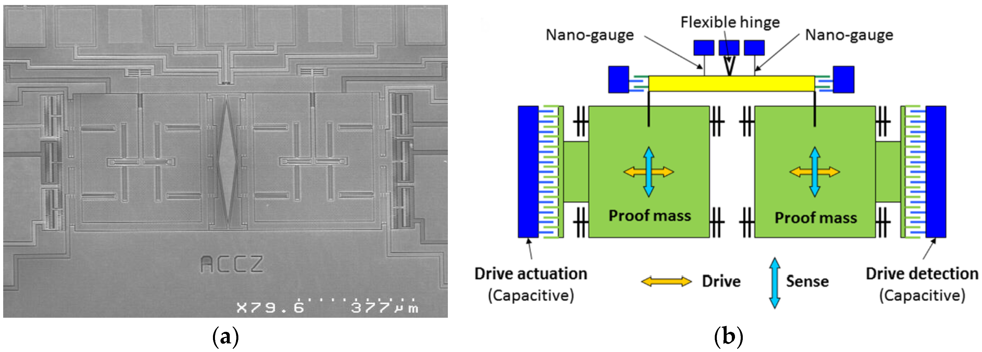
The studied device (Figure 1) is a z-axis dual-mass vibratory MEMS gyroscope [4] characterized by its two drive mode resonance frequencies corresponding to the anti-phase mode (fDa = 17.18 kHz) and the in-phase mode (fDi = 19.16 kHz). A typical quality factor of 13, 500 is expected for this component [1] but a sealing issue led to a value of only 600 due to poor vacuum in the cavity. Capacitive finger combs are used for actuation and detection of the drive axis motion whereas piezoresistive nanogauges pick up the motion along the sense axis. When the gyroscope is operating, a Phase-Locked Loop (PLL) circuit controls the drive axis motion, which needs to be insensitive to external mechanical vibrations for keeping the PLL in operation. In the next sections, we will focus on a stiffness correction method that enables to cancel the effect of external mechanical vibrations on device operation.
3. Experimental Details
The core idea of the method is to balance the dual-mass gyroscope by tuning the suspension stiffness through the negative electrostatic spring effect. The objective is to compensate the structure unbalance generated by fabrication imperfections. It consists in applying a trimming voltage (Vtr) at the drive actuation electrode within the range of −25 V to 25 V. In normal operation, the drive axis of the gyroscope is electrostatically actuated at the frequency of the anti-phase mode, ideally insensitive to vibrations. Here, in order to simplify the experiment, no electrostatic actuation is performed on the anti-phase mode. As a result, the sensitivity to external mechanical vibrations at the anti-phase mode frequency can be evaluated directly.
3.1. Experimental Set-Up
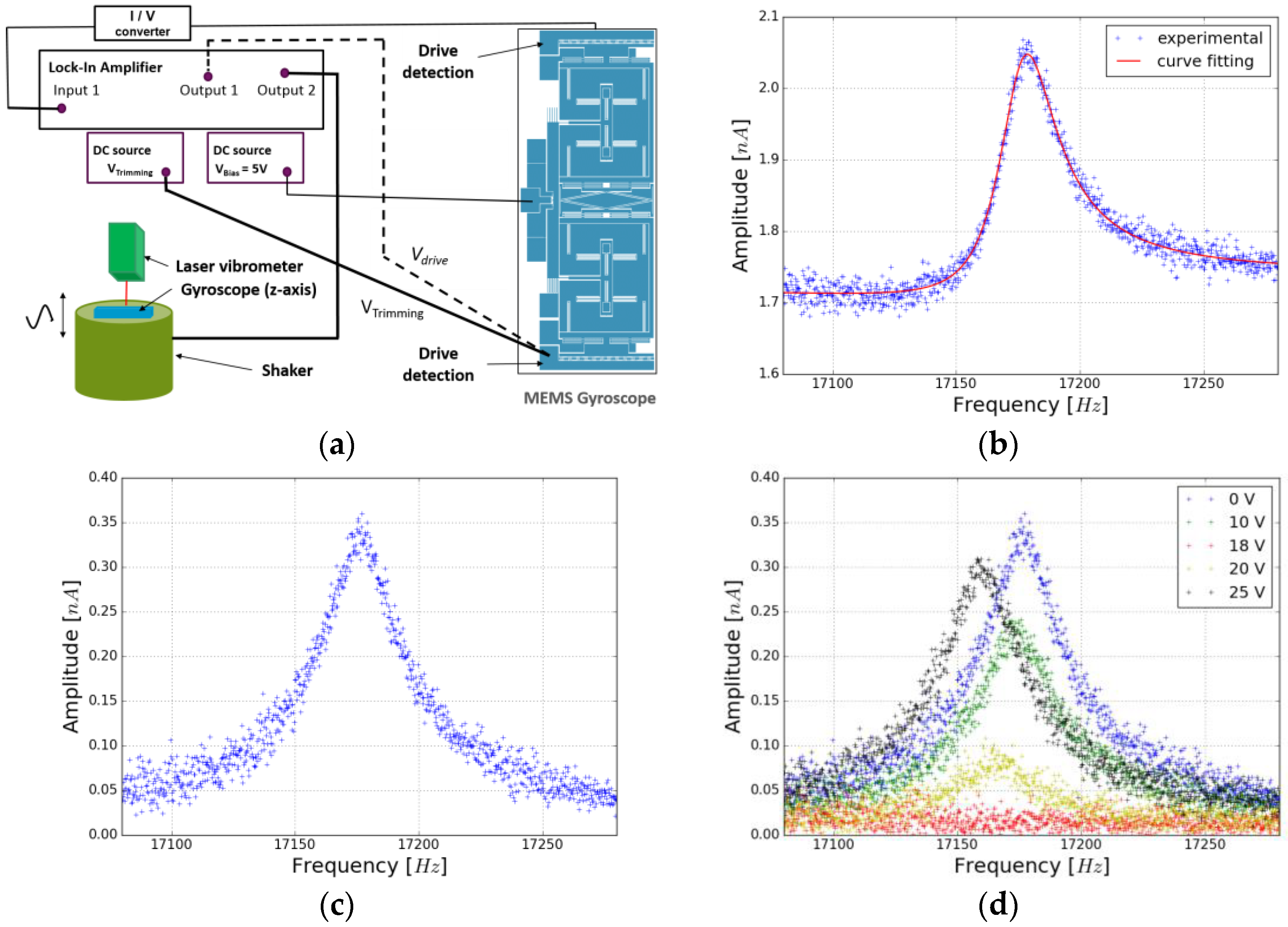
The vibration experiments (Figure 2a) are performed with a shaker (DataPhysics V20), which enables accelerations up to 5 g near the anti-phase mode frequency (fDa). Vibration amplitude is monitored by a laser vibrometer (SIOS). The shaker is driven by a Lock-In-Amplifier (LIA HF2LI Zurich Instrument), which carries out a frequency sweep around fDa (fDa ± 100 Hz) and tunes a specific signal amplitude to have the expected vibration acceleration. The detection of the drive axis motion is performed by the LIA preceded by an I/V converter to sense the capacitance change of the drive axis transduction circuit. Two DC sources (Keithley 2400) are used: the first one at 5 V is applied on the moving part to bias the transduction circuit and generate the readout signal. The second one Vtr is applied to the drive actuation electrode to rectify the stiffness unbalance of the dual-mass structure.
3.2. Curve Fitting Method
The acquisition of the gyroscope output signal (Figure 2b) requires to use a curve fitting method to distinguish the electromechanical signal from the background signal. For clarity of the result, the background signal is removed (Figure 2c). The curve fitting method allows to extract the resonance frequency, the amplitude of the pic and two parameters that account for the background signal. Indeed, we make the assumption that the background signal varies linearly with the frequency. The excellent agreement between experimental points and the result of curve fitting (Figure 2b) validates the model used to describe the component and the assumption made for the background signal.
3.3. Experimental Results
Several gyroscopes have been tested and exhibit a similar behavior. In this paper, we present the results of one of them, whose main properties are given in Section 2. Figure 2d clearly shows the effect of Vtr on the amplitude of the gyroscope output signal and the ability to improve its resilience to vibrations when it undergoes an acceleration of 5 g in the vicinity of the anti-phase mode frequency. The experiment has been conducted for various vibration accelerations. The results, gathered in Figure 3a, put forward a trimming voltage of around 18 V that minimizes the amplitude of the gyroscope output signal independently of the vibration accelerations undergone by this gyroscope. The sensitivity to external vibrations is then reduced by a factor of at least 30, from a sensitivity of 80 pA/g without trimming voltage to a sensitivity of 2 pA/g for Vtr = 18 V. The trimming voltage introduces a negative electrostatic spring constant that balances the anti-phase mode. As expected, the resonance frequency of the anti-phase mode, illustrated in Figure 3b, is shifted down. Colored areas represent data for which the extraction of the resonance parameters is not efficient due to weak electromechanical signal. When the drive axis is insensitive to external mechanical vibrations (Vtr = 18 V), the shift of anti-phase mode resonance frequency corresponds to 0.06% of the resonance frequency without trimming voltage. It represents a decrease of the spring constant lower than 0.1% of the initial value.
4. Conclusions
The sensitivity to external mechanical vibrations is expected to be proportional to the quality factor and also depends on the unbalance of the dual mass structure. The gyroscope, used in this study, is characterized by a high vibration sensitivity and thus a large structure unbalance compared with the one used in a previous paper [1]. This work confirms the ability of the stiffness correction method to fix this issue independently of the structure unbalance. In this experiment, a significant trimming voltage of 18 V is applied on the drive actuation electrode. However, the sizing of a dedicated capacitive electrode may lower this voltage down to 1 V or 2 V.
Knowing that the stoppers are reached for an amplitude of the output signal around 2 nA [1], one can estimate the acceleration threshold accepted by the studied gyroscope having a larger quality factor around 13, 500. With the stiffness correction method, this threshold can shift from 1.1 g to 44 g, corresponding to a sensitivity of respectively 1.8 nA/g and 45 pA/g.
Further work will focus on the design of a trimming electrode to efficiently correct the structure unbalance and will propose a gyroscope that meets stringent specifications required for automotive applications.
Conflicts of Interest
The authors declare no conflict of interest.
References
- Koumela, A.; Poulain, C.; Le Goc, C.; Verdot, T.; Joet, L.; Rey, P.; Berthelot, A.; Jourdan, G. Resilience to vibration of a tuning fork MEMS gyroscope. Procedia. Eng. 2016, 168, 1725–1730. [Google Scholar] [CrossRef]
- Trusov, A.A.; Zotov, S.A.; Shkel, A.M. Electrostatic regulation of quality factor in non-ideal tuning fork MEMS. In Proceedings of the 2011 IEEE SENSORS, Limerick, Ireland, 28–31 October 2011; pp. 20–23. [Google Scholar]
- Guan, Y.; Gao, S.; Liu, H.; Jin, L.; Zhang, Y. Vibration sensitivity reduction of micromachined tuning fork gyroscopes through stiffness match method with negative electrostatic spring effect. Sensors 2016, 16. [Google Scholar] [CrossRef] [PubMed]
- Walther, A.; Savoye, M.; Jourdan, G.; Renaux, P.; Souchon, F.; Robert, P.; Blanc, C.L.; Delorme, N.; Gigan, O.; Lejuste, C. 3-Axis gyroscope with Si nanogage piezo-resistive detection. In Proceedings of the IEEE 25th International Conference on Micro Electro Mechanical Systems (MEMS), Paris, France, 29 January–2 February 2012; pp. 480–483. [Google Scholar]
Figure 1.
(a) MEB photograph of the z-axis gyroscope; (b) Principle of the dual-mass MEMS gyroscope showing the drive actuation/detection electrodes and the two nanogauges, used for the piezoresistive transduction of the sense mode.
Figure 1.
(a) MEB photograph of the z-axis gyroscope; (b) Principle of the dual-mass MEMS gyroscope showing the drive actuation/detection electrodes and the two nanogauges, used for the piezoresistive transduction of the sense mode.

Figure 2.
(a) Experimental set-up based on a double LIA. Output 2 drives the shaker while Output 1 and Input 1 correspond to the actuation and detection of the drive mode respectively. The dotted line represents the electrostatic actuation (not used in this paper); Response of the gyroscope submitted to external mechanical vibrations at 5 g in the vicinity of the anti-phase mode frequency: (b) Output signal for Vtr = 0 V, i.e., electromechanical and background signal; (c) Output signal for Vtr = 0 V after background removal; (d) Output signal for various trimming voltages applied to the drive actuation electrode in the range of 0 V to 25 V.

Figure 3.
(a) Effect of Vtr on the output signal amplitude for different accelerations (2 g–5 g); (b) Frequency shift as a function of Vtr. The vibration acceleration is given at ±1 g.
Figure 3.
(a) Effect of Vtr on the output signal amplitude for different accelerations (2 g–5 g); (b) Frequency shift as a function of Vtr. The vibration acceleration is given at ±1 g.

© 2017 by the authors. Licensee MDPI, Basel, Switzerland. This article is an open access article distributed under the terms and conditions of the Creative Commons Attribution (CC BY) license (http://creativecommons.org/licenses/by/4.0/).
Share and Cite
MDPI and ACS Style
Janioud, P.; Koumela, A.; Poulain, C.; Rey, P.; Berthelot, A.; Morfouli, P.; Jourdan, G. Tuning the Anti-Phase Mode Sensitivity to Vibrations of a MEMS Gyroscope. Proceedings 2017, 1, 355. https://doi.org/10.3390/proceedings1040355
AMA Style
Janioud P, Koumela A, Poulain C, Rey P, Berthelot A, Morfouli P, Jourdan G. Tuning the Anti-Phase Mode Sensitivity to Vibrations of a MEMS Gyroscope. Proceedings. 2017; 1(4):355. https://doi.org/10.3390/proceedings1040355
Chicago/Turabian StyleJanioud, Pierre, Alexandra Koumela, Christophe Poulain, Patrice Rey, Audrey Berthelot, Panagiota Morfouli, and Guillaume Jourdan. 2017. "Tuning the Anti-Phase Mode Sensitivity to Vibrations of a MEMS Gyroscope" Proceedings 1, no. 4: 355. https://doi.org/10.3390/proceedings1040355