Energy Harvesting for Sensors of Structural Integrity in Wind Power Stations †


KEmikro, RWTH Aachen University, Aachen 52062, Germany
*
Author to whom correspondence should be addressed.
†
Presented at the Eurosensors 2017 Conference, Paris, France, 3–6 September 2017.
Proceedings 2017, 1(4), 577; https://doi.org/10.3390/proceedings1040577
Published: 8 August 2017
(This article belongs to the Proceedings of Proceedings of Eurosensors 2017, Paris, France, 3–6 September 2017)
Abstract
:The structural integrity of the rotors of wind power stations can be monitored by a variety of sensors. However, the power supply of the employed sensors should not be connected by cable because lightning strikes are provoked that way. Therefore, energy harvesting systems are an interesting alternative. Three concepts for electrical power generation by harvesting the energy from the movements inside of rotor blades of wind power stations are described and compared to each other. Inside of such rotor blades, large vibration amplitudes of up to 15 cm are available but only at a frequency of a few Hertz. The available space is on the order of 20 × 20 × 40 cm3. A beam equipped with piezos and repelling magnets turned out being the most promising solution.
1. Introduction
The decision when a wind power station shall be replaced by a new one is influenced by the expectation how long the rotors will remain intact. Unfortunately, the wear of light weight components form fiber-reinforced polymers such as the rotor blades is not easy to detect. Several concepts of monitoring the structural integrity of the rotors of wind power stations are subject to scientific investigations [1].
A common problem of all sensors mounted on or inside of a rotor blade is that the power supply of the sensor and for signal transmission should not be connected by cable, because lightning strikes are provoked that way. Exchanging batteries is also not easy in a rotor, and therefore, energy harvesting systems generating the electric power for sensing and radio transmission of the signal is an interesting alternative. The energy required for one measurement and signal transmission is in the order of 2.5 mJ every 10 min. Therefore, the average power to be harvested is in the order of 4 μW.
The main problem of this application is the low frequency of vibrations inside of a rotor blade of only a few Hertz. To charge a battery or capacitor, rectification of the alternating voltage generated is required. Rectifying circuits usually need a minimum input voltage of 2 V to work properly which is difficult to achieve with a low frequency excitation. On the other hand, there is ample of space available allowing devices, several kg in weight and approximately 20 × 20 × 40 cm3 in volume.
In this paper, construction and test of energy harvesting by frequency enhancing through vibrating springs and an arrangement of several magnets are described. Besides this, the frequency range of a vibrating beam was enlarged by magnets mounted repulsively.
2. Hollow Cylinder
Halim and Park developed an energy harvesting device enhancing the velocity of a moving body by transferring its kinetic energy to magnets vibrating at a higher frequency [2]. This is achieved with a hollow cylinder inside of which a ball is rolling back and forth and giving an impact to magnets mounted at both ends of the cylinder (cf. Figure 1). The magnets are mounted at the end of springs which start vibrating at their resonance frequency due to the impact. Since the resonance frequency can be larger than the frequency of the excitation by the rolling ball, the magnets are moving faster than the ball. On the outside of the cylinder there are mounted coils at the position of the magnets and the moving magnets generate a voltage in the coils by induction.
To achieve a large enough voltage, a hollow cylinder, 15 and 2.3 cm in length and diameter, respectively, was constructed larger than in [2]. It was exposed to horizontal vibrations at frequencies in the range of 7 to 10 Hz with mechanical amplitude of up to 5 mm. A ball from lead alternately struck against two permanent magnets (Nd2Fe14B from Webcraft GmbH, Germany). After each impact the springs oscillated at their resonance frequencies of up to 70 Hz and with exponentially decaying amplitude. The mass of the ball and the total hollow cylinder structure were 39 g and 111 g, respectively. At the cylinder magnets, 20 and 2 mm in diameter and height, respectively, an effective magnetic flux density of 78 mT was measured with a Hall probe. On both springs, three magnets were mounted as a stack. The mass m of each stack was 14 g and the total magnetic flux density was measured to be approximately 230 mT. Four spring pairs with spring constants of 0.45, 0.95, 1.97 and 2.73 N/mm were investigated. The corresponding resonance frequencies were calculated as 28, 41, 59 and 70 Hz.
As shown in Figure 2, the generated voltage was damped out in 40 ms and the maximum voltage was just 0.5 V. Obviously more energy needs to be transferred to the vibrating magnets. An estimation results in a minimum mass of 1.75 kg for the ball to achieve the required voltage of 2 V for all the time between two contacts of the ball.
3. Halbach Slider
Zhu et al. introduced an energy harvesting device consisting of a special arrangement of permanent magnets moving above two coils [3]. This arrangement is called a Halbach arrangement providing an enhanced magnetic field on one side and a reduced one on the opposite side [4,5] (Figure 3). The Halbach slider is guided by two rods. At the ends of the rods there are mounted springs repelling the slider when it arrives there. The free path of the slider before it arrives at the opposite spring is 6 mm and the overall dimensions of the slider with housing are 90 × 70 × 40.5 mm3.
On the slider, 13 permanent magnets (Nd2Fe14B) were mounted such that their magnetization axes were arranged as shown in Figure 3. This arrangement results in a doubled magnetic field on one side of the array and a strongly reduced one on the opposite side [3]. Three coils each with 200 turns were mounted above the magnets. Each coil has a square profile, internal resistance, inductance and length of 15.8 Ω, 400 μH and 3 mm, respectively.
The voltage induced at all coils in series was investigated at 8, 9 and 10 Hz excitation frequency. Springs with a stiffness of 2.34 N/mm and rods with a length of 90 mm were used. The voltage curve obtained at 10 Hz is shown in Figure 4. The maximum voltage generated was 0.85 V.
For energy harvesting in the blades of a wind power station, a five times larger voltage is desirable. This obviously can be achieved with a five times larger system, e.g., 90 × 350 × 40.5 mm3, in outer dimensions, equipped with 15 coils in series.
The voltages generated as a function of frequency generated by the hollow cylinder and the Halbach slider are shown in Figure 5. Unfortunately no measurements could be performed at lower frequencies. However, there is no indication of a resonance and it is expected that the generated voltages are not much smaller at 1 Hz or less although the smaller frequency will result in a smaller power.
4. Piezoelectric Beam
A piezoelectric stripe mounted on a vibrating beam generates comparatively large voltages. However, the electrical capacity of a piezo is small, and therefore, some electronics is required to charge a battery. The electronics employed for the investigation described here (EHE004 from Midé Technology Corporation, Medford, MA, USA) needs at least 20 V input to charge a capacitor or battery at 3 V.
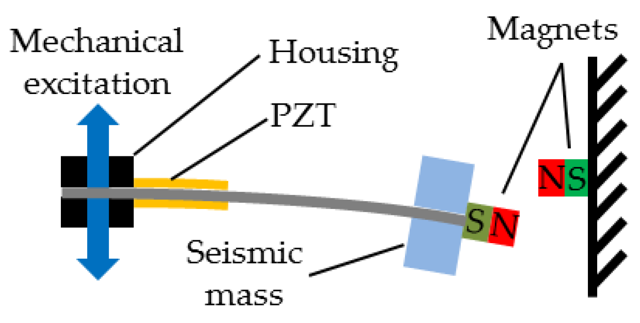
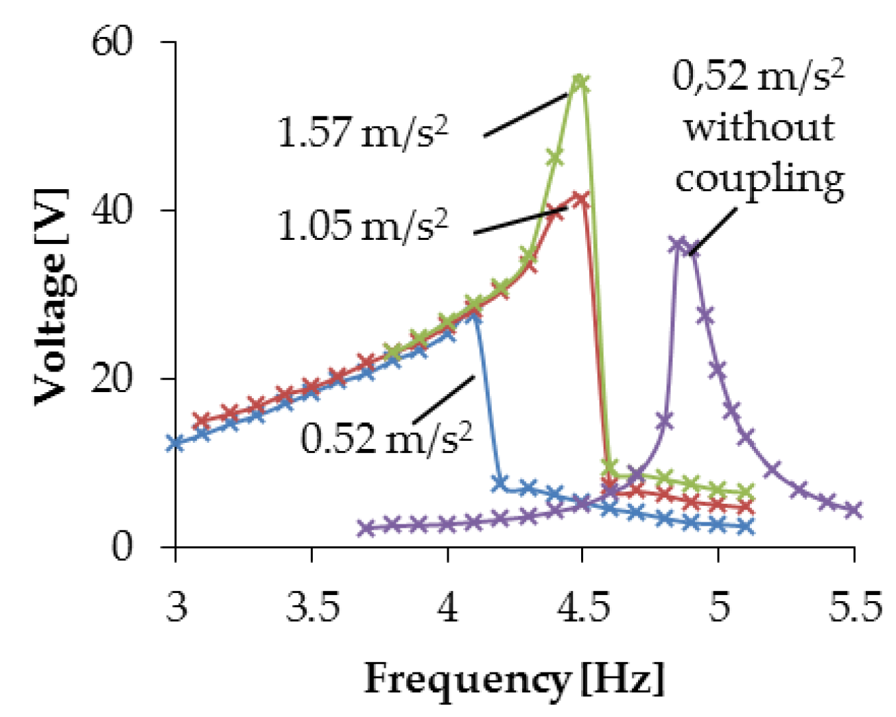
The resonance peak of vibrating beams fixed at one end can be broadened by mounting magnets at their free end and placing a fixed repelling magnet opposite to it [6,7] (cf. Figure 6). To investigate this, disk-shaped magnets S-20-02-N with 1.3 T from Webcraft GmbH, Germany were mounted at the free ends of cantilevers from carbon fiber reinforced polymer. Opposite to these magnets, similar magnets were fixed (cf. Figure 7). Piezos from PZT, 0.2, 23, and 46.9 mm in thickness, width and length, respectively, were bonded on both sides of the cantilever and electrically connected in series. The fixed end of the cantilever was accelerated normal to its surface. A mass of 100 g was attached to the end of the beam and the distance between repellent magnets was 10 mm. The open circuit voltages were measured with and without fixed magnets as shown in Figure 8.
Without magnetic coupling there is seen a resonance at 4.9 Hz. The coupling results in higher voltages generated at lower frequencies. At low frequencies the generated voltage is not larger than 20 V and therefore, not enough for charging a battery or capacitor. However, if on each side of the beam there are mounted two piezos with half the width and connected in series, the voltage is doubled and appears to be large enough.
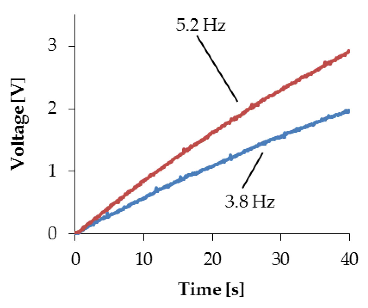
A capacitor with 200 μF was connected to the rectification circuit and charged at 0.52 m/s2 acceleration a beam with a mass of 100 g at its free end and at 5.2 Hz and by another beam with 140 g at 3.8 Hz. The charging of the capacitor is shown in Figure 9.
5. Conclusions
If constructed large enough, all three devices appear suitable for energy harvesting from the low-frequency vibrations inside of the rotor blades of wind power stations. Unfortunately the available equipment was not suitable for measurements at less than 3 Hz, but the extrapolation of the curves indicates that energy harvesting should be possible also at lower frequencies. Most promising are PZT stripes mounted on vibrating beams equipped with repelling magnets at their free ends because they can be designed comparatively small and light.
Acknowledgments
With authors thank the German Federal Ministry of Education and Research for financial support under fund number 01LY407A.
Conflicts of Interest
The authors declare no conflict of interest. The founding sponsors had no role in the design of the study; in the collection, analyses, or interpretation of data; in the writing of the manuscript, and in the decision to publish the results.
References
- Ciang, C.C.; Lee, J.-R.; Ban, H.-J. Structural health monitoring for a wind turbine system: A review of damage detection methods. Meas. Sci. Technol. 2008, 19, 122001. [Google Scholar] [CrossRef]
- Halim, M.; Park, J. A non-resonant frequency up-converted electromagnetic energy harvester from human-body-induced vibration for hand-held smart system applications. J. Appl. Phys. 2014, 115, 094901. [Google Scholar] [CrossRef]
- Zhu, D.; Beeby, S.; Tudor, J.; Harris, N. A planar electromagnetic vibration energy harvester with a Halbach array. In Proceedings of the PowerMEMS 2011, Seoul, Korea, 15–18 November 2011. [Google Scholar]
- Halbach, K. Design of permanent multipole magnets with oriented rare earth cobalt material. Nucl. Instrum. Methods 1980, 169, 1–10. [Google Scholar] [CrossRef]
- Mallinson, J.C. One-sided fluxes—A magnetic curiosity? IEEE Trans. Magn. 1973, 9, 678–682. [Google Scholar] [CrossRef]
- Ferrari, M.; Ferrari, V.; Guizettei, M.; Andò, B.; Baglio, S.; Trigona, C. Improved energy harvesting from wideband vibrations by nonlinear piezoelectric converters. Procedia Chem. 2009, 1, 1203–1206. [Google Scholar] [CrossRef]
- Tang, L.; Yang, Y.; Soh, C.-K. Improving funcionality of vibration energy harvesters using magnets. J. Intell. Mater. Syst. Struct. 2012, 23, 1433–1449. [Google Scholar] [CrossRef]
Figure 1.
Schematic drawing of the hollow cylinder.

Figure 2.
Open circuit voltage measured at one coil of the hollow cylinder at 9 Hz and excited with 3.1 mm amplitude corresponding to an acceleration of 9.9 mm/s2.
Figure 2.
Open circuit voltage measured at one coil of the hollow cylinder at 9 Hz and excited with 3.1 mm amplitude corresponding to an acceleration of 9.9 mm/s2.

Figure 3.
Photo (left) and principle (right) of the Halbach arrangement of 13 magnets on the slider.
Figure 3.
Photo (left) and principle (right) of the Halbach arrangement of 13 magnets on the slider.

Figure 4.
Open circuit voltage measured with the Halbach slider at 10 Hz and an acceleration of 8.3 m/s2.
Figure 4.
Open circuit voltage measured with the Halbach slider at 10 Hz and an acceleration of 8.3 m/s2.

Figure 5.
Maximum voltage amplitudes as a function of excitation frequency measured at Halbach slider and hollow cylinder.
Figure 5.
Maximum voltage amplitudes as a function of excitation frequency measured at Halbach slider and hollow cylinder.

Figure 6.
PZT stripes on a beam with repellent magnet at its free end (not to scale).

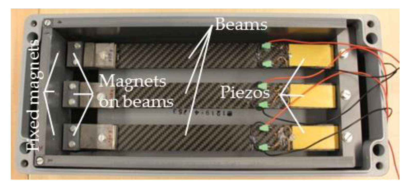
Figure 7.
Three beams with PZT piezos and at their free ends repellent magnets.

Figure 8.
Open circuit voltages measured without and with magnetic coupling at different accelerations.
Figure 8.
Open circuit voltages measured without and with magnetic coupling at different accelerations.

Figure 9.
Charging of a capacitor with 200 μF with PZT stripes on vibrating beams.

Publisher’s Note: MDPI stays neutral with regard to jurisdictional claims in published maps and institutional affiliations. |
© 2017 by the authors. Licensee MDPI, Basel, Switzerland. This article is an open access article distributed under the terms and conditions of the Creative Commons Attribution (CC BY) license (https://creativecommons.org/licenses/by/4.0/).
Share and Cite
MDPI and ACS Style
Behnke, C.; Schomburg, W.K. Energy Harvesting for Sensors of Structural Integrity in Wind Power Stations. Proceedings 2017, 1, 577. https://doi.org/10.3390/proceedings1040577
AMA Style
Behnke C, Schomburg WK. Energy Harvesting for Sensors of Structural Integrity in Wind Power Stations. Proceedings. 2017; 1(4):577. https://doi.org/10.3390/proceedings1040577
Chicago/Turabian StyleBehnke, Christopher, and Werner Karl Schomburg. 2017. "Energy Harvesting for Sensors of Structural Integrity in Wind Power Stations" Proceedings 1, no. 4: 577. https://doi.org/10.3390/proceedings1040577