Proceeding Paper

Wall Shear Stress Calorimetric Micro-Sensor Designed for Flow Separation Detection and Active Flow Control †

1
University Lille, CNRS, Centrale Lille, ISEN, University Valenciennes, UMR 8520—IEMN, LIA LICS/LEMAC, Lille, France
2
Office National d'Etudes et de Recherches Aerospatiales, Chemin de la Hunière, 91123 Palaiseau, France
3
Fluiditech, Thurmelec, 68840 Pulversheim, France
*
Author to whom correspondence should be addressed.
Presented at the Eurosensors 2017 Conference, Paris, France, 3–6 September 2017.
Proceedings 2017, 1(4), 376; https://doi.org/10.3390/proceedings1040376
Published: 9 August 2017
(This article belongs to the Proceedings of Proceedings of Eurosensors 2017, Paris, France, 3–6 September 2017)

Abstract

:
This paper presents an efficient and high-sensitive micro-sensor designed for wall shear stress measurement. The main technical application targeted is flow separation detection for closed-loop active flow control. The sensor is a temperature-resistance transducer operating on heat transfer. The device is micro-structured with three substrate-free wires presenting a high aspect ratio, and periodic perpendicular micro-bridges ensuring mechanical toughness and thermal insulation. This design achieves a homogeneous temperature distribution along the wires. Welded on a flexible printed circuit, the sensor is wall-mounted on a wind tunnel. The experiments, conducted in both attached and separated flow configurations, demonstrate the sensor sensitivity to wall shear stress up to 2.4 Pa and the ability of the 3-wires based design to perform flow direction sensing for back-flow detection.

1. Introduction

The reduction of fuel burn and the related CO2 emission is one of the main current goals of research in vehicles and one of the ways is to improve the aerodynamic performances. Active flow control is one of the means to reach this objective for current high lift devices [1]. At high angle of attack, the apparition of flow separation decreases the aerodynamic performances on two aspects: the lift is reduced and the drag is increased. Therefore, the main objective of active flow control is to keep the flow attached on the largest part of the wing. Accurate near wall flow measurements play a key role for this achievement. Sensors are needed to measure flow parameters at high frequencies with a high spatial resolution [2] and micro-electro-mechanical system (MEMS) sensors are potential candidates for precise and located measurements.
One of the main flow parameters considered is the wall shear stress τ, proportional to the derivative of the flow velocity u with respect to the vertical axis y. At the flow separation point the wall shear stress vanishes and becomes negative when the flow is separated. Separation is characterized by a recirculation zone, where the flow direction changes. The wall shear stress variations are usually indirectly measured using thermal anemometry. The basic principle of anemometry involves a metallic wire heated by an electric current and cooled by the surrounding flow. The corresponding sensors are called hot-wire sensors when the wire is free in the flow, and hot-film sensor when the wire is deposited on an insulating film. Both hot-wires and hot-films can be manufactured using micro-machining techniques [3,4].
In this paper, we present the work realized on a novel and efficient thermal micro-sensor designed as an intermediate structure between hot-films and hot-wires, for flow separation detection [5,6,7]. This transducer is able to measure wall shear stress variations and to detect flow direction, especially the back-flow present in a separated flow. This paper presents the design of the sensor, then the electrical and thermal characterizations and finally some experiments conducted in a turbulent boundary layer wind tunnel, in attached and separated flows configurations to characterized it.

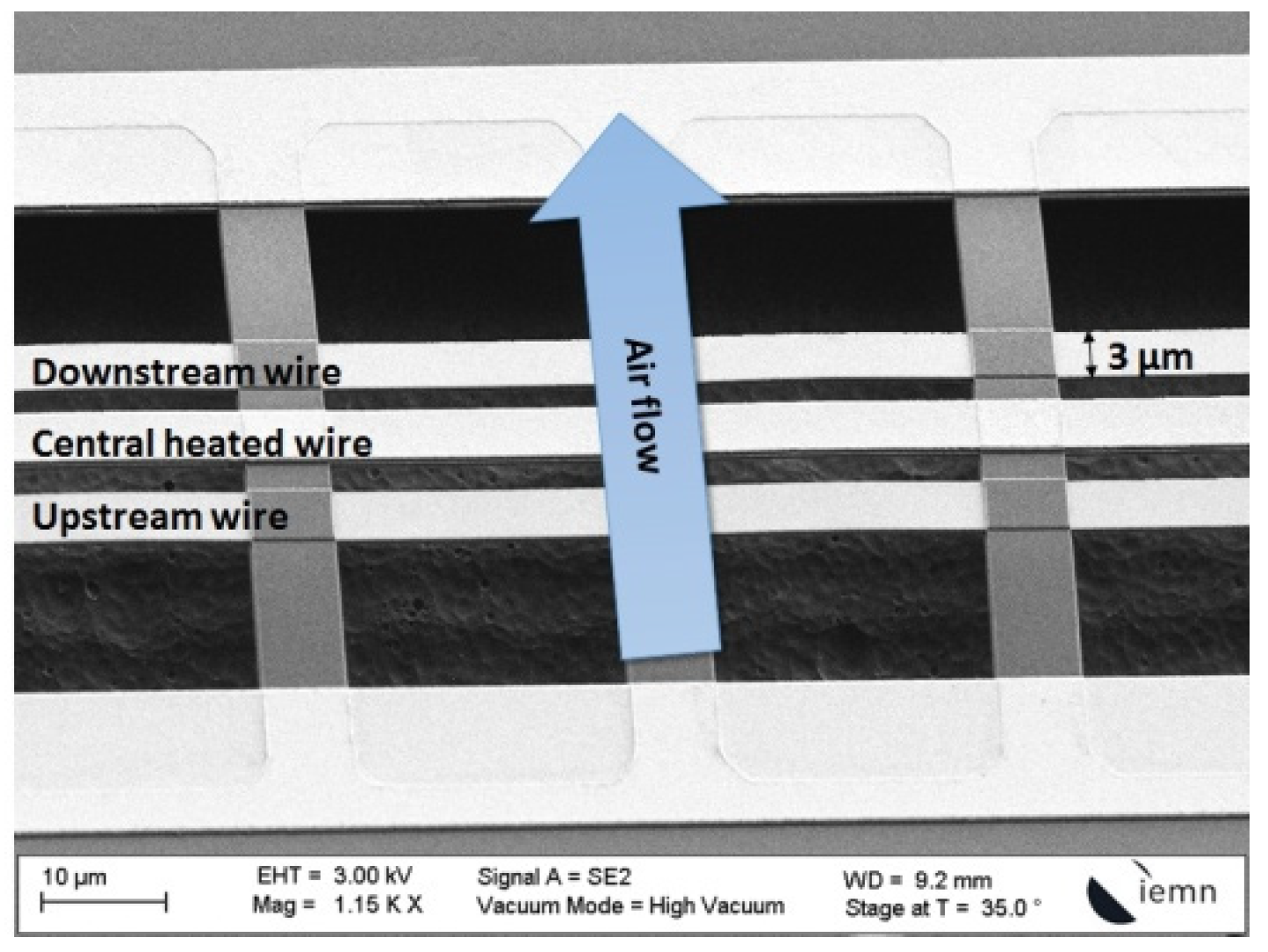
2. The Sensor Design

The sensor design aims to balance the advantages of both hot-wire sensors (sensitivity, limited heat losses) and hot-film sensors (robustness). The structure is indeed composed of three parallel substrate-free wires, mechanically supported by silicon oxide micro-bridges, as seen in a Scanning Electron Microscopy picture and schematic of the sensor (Figure 1). As the wires are separated from the substrate like hot-wire sensors, the thermal losses are limited. The mechanical support by a set of regularly spaced silicon oxide micro-bridges allows the wires to reach a high aspect ratio with a total length of 1 mm for 3 μm wide and enables toughness to the flow.
The central wire is the hot wire as classically defined, which works similarly to conventional hot-wire sensors as it is heated by an electric current. As the flow velocity cools the wire by forced convection, the temperature variations are transduced by the resistance variations of the wire. The two other sensing wires are placed on both sides of the central wire. The central heater heats them. They are used to detect the flow direction using calorimetric principle. The wires are indeed designed to be set perpendicularly to the flow. Therefore the lateral wire upstream the flow is more cooled than the lateral wire downstream the flow and the resistance difference between them indicates the flow direction.

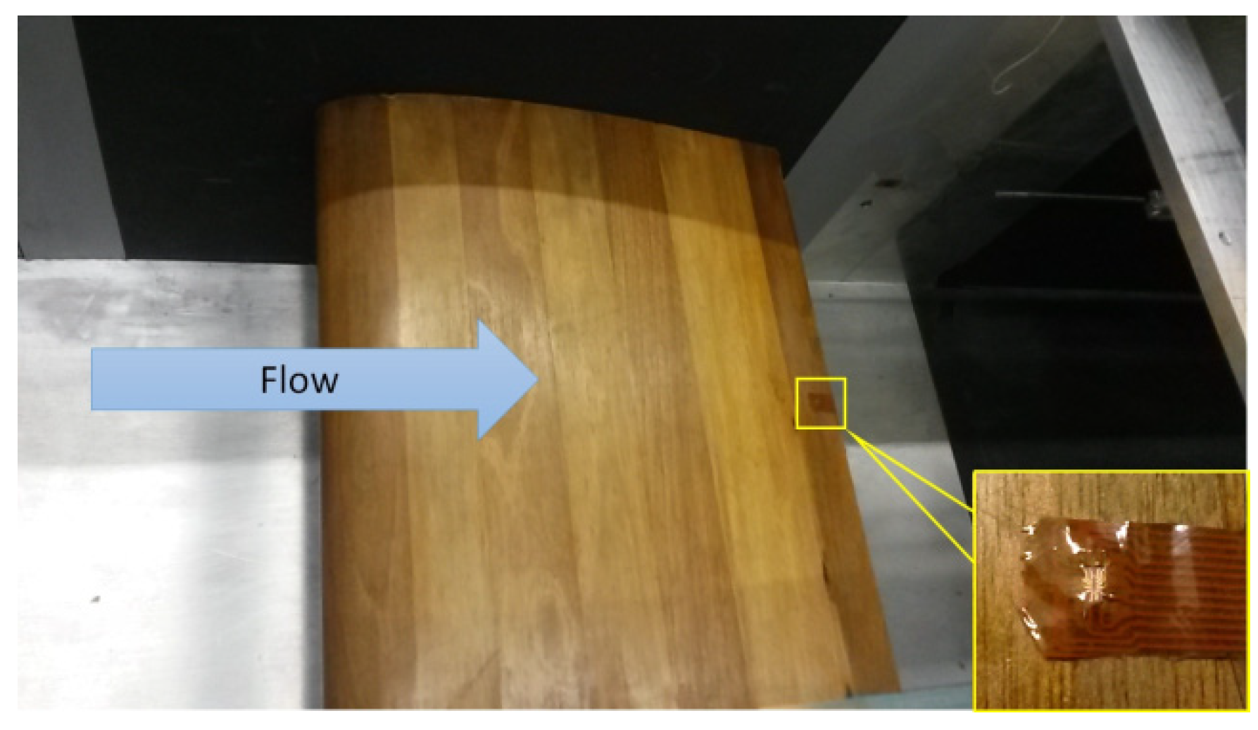
3. Experimental Setup

The sensor was calibrated in a turbulent boundary layer wind tunnel (Figure 2a) as previously published in [6]. The calibration results are presented in Figure 2b. The experiments presented in the current paper, consist in placing the sensor at the trailing edge of a NACA0020 airfoil model (Figure 3) and evaluating the sensor ability to detect flow separation. The wing is 30 cm wide and has a 25 cm long chord. The sensor is stuck on surface of the wing, placed at 1 cm from the trailing edge corresponding to x / c = 0.96 . The experiment consisted in changing the angle of attack (AOA) of the airfoil model and comparing the results obtained to XFOIL numerical simulations. The setup of the experiment enables to change the AOA by 5° step. Three different flow velocities were studied: 18 m/s, 22 m/s and 26 m/s, corresponding respectively to Reynolds number of 288,461, 352,564 and 416,667, based on the chord.

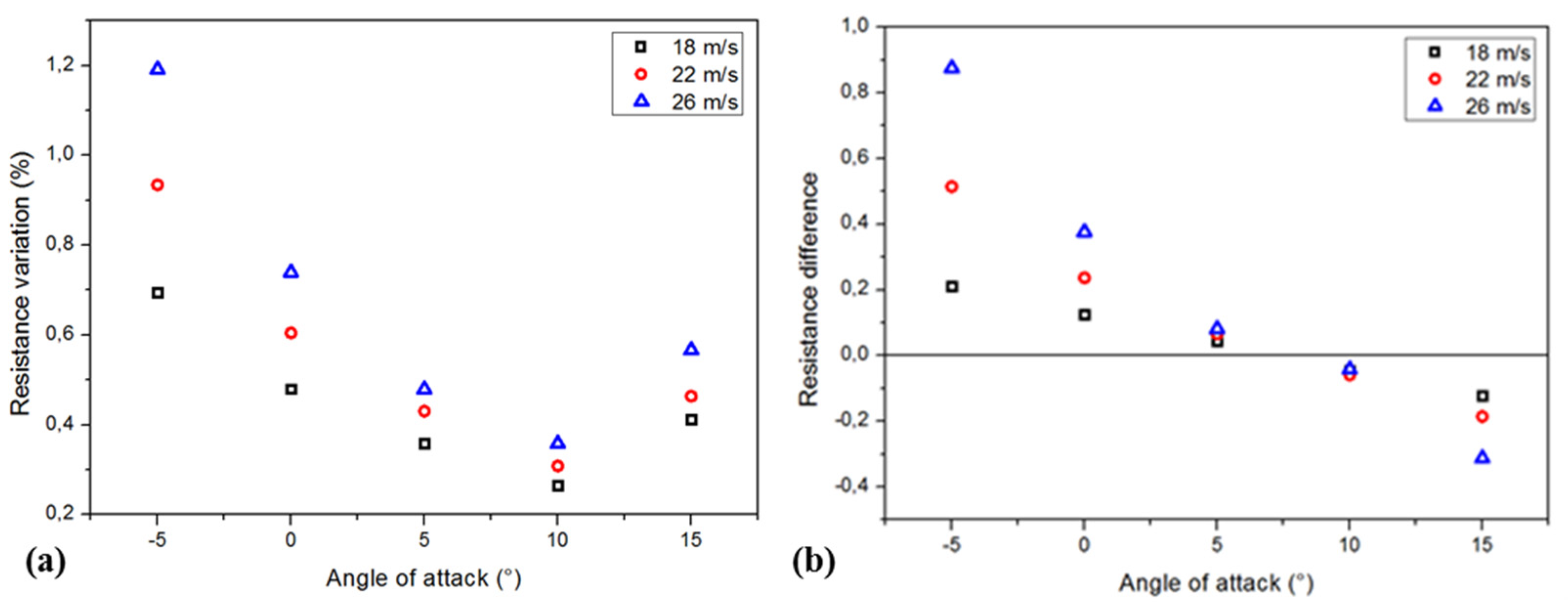
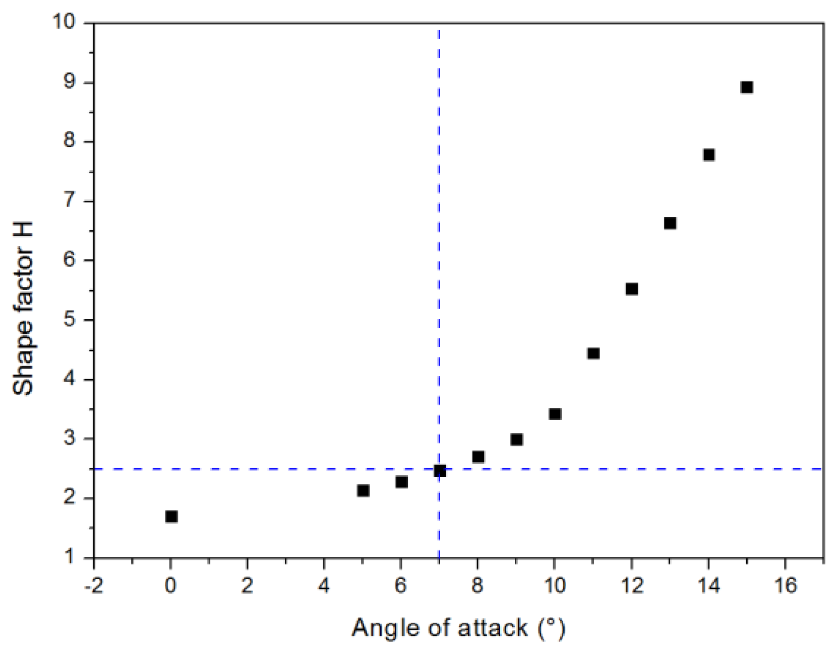
4. Results and Discussion

The experiment results are presented in Figure 4a,b. Figure 4a presents the resistance variation of the central wire, corresponding to the amplitude of wall shear stress variation and Figure 4b shows the difference of resistance between the two lateral wires, indicative of the flow direction.
In Figure 4a, the sensor resistance variation decreases while changing the AOA, up to 10°, indicating that the flow velocity at the sensor location decreases. It increases at 15° compared to 10°. The flow separation occurs then either between 5° and 10° or between 10° and 15°.
In Figure 4b, the difference of resistance between the two lateral wires changes its sign between 5° and 10°. When flow separation occurs, the flow reverses its direction. Compared to the Figure 4a, the additional information provided by Figure 4b states that separation occurs between 5° and 10°, for the three flow velocities.
XFOIL simulations were realized to validate the experimental results. Figure 5 presents the results for 22 m/s and expresses the H shape factor versus the angle of attack. [8] states that flow separation occurs for H superior to 2.5 for a turbulent flat plate, and the numerical results demonstrates a separation for 7°, validating experimental data. The same simulations were performed for 18 m/s and 26 m/s, indicating separation for respectively 8° and 6°.

5. Conclusions

As a conclusion, this paper presents the work realized on the aerodynamic characterizations of an original MEMS thermal flow sensor designed for flow separation detection. The experiments demonstrated the sensor ability to measure the wall shear stress amplitude variations using classical thermal anemometry principle, and to detect the flow direction at the same location. Flow separation on a airfoil model was detected by the sensor and the results were confirmed using numerical simulation on XFOIL software. Obtaining simultaneously the variations of the wall shear stress amplitude and direction increases the stability and robustness of flow control strategies. Further work is currently done on a flap model to perform active flow control using the presented MEMS sensors as sensing devices and pulsed jets for actuation.

Acknowledgments

This work was funded by the French National Research Agency (ANR) in the framework of the ANR ASTRID “CAMELOTT” Project. It was supported by the regional platform CONTRAERO in the framework of the CPER ELSAT 2020 Project, co-financed by the European Union with the European Regional Development Fund and the French State and the Hauts de France Region under the State Region Contracts (CPER). The authors also thank RENATECH, the French national nanofabrication network, and FEDER.

Conflicts of Interest

The authors declare no conflict of interest.

References

  1. Gad-el-Hak, M. Flow Control: The Future. J. Aircr. 2001, 38, 402–418. [Google Scholar] [CrossRef]
  2. Löfdahl, L.; Gad-el-Hak, M. MEMS-based pressure and shear stress sensors for turbulent flows. Meas. Sci. Technol. 1999, 10, 665. [Google Scholar] [CrossRef]
  3. Talbi, A.; Gimeno, L.; Gerbedoen, J.C.; Viard, R.; Soltani, A.; Mortet, V.; Preobrazhensky, V.; Merlen, A.; Pernod, P. A micro-scale hot wire anemometer based on low stress (Ni/W) multi-layers deposited on nano-crystalline diamond for airflow sensing. J. Micromech. Microeng. 2015, 25, 125029. [Google Scholar] [CrossRef]
  4. Miau, J.J.; Le, T.S.; Yu, J.M.; Tu, J.K.; Wang, C.T.; Lebiga, V.; Mironov, D.; Pak, A.; Zinovyev, V.; Chung, K.M. MEMS thermal film sensors for unsteady flow measurement. Sens. Actuators Phys. 2015, 235, 1–13. [Google Scholar] [CrossRef]
  5. Viard, R.; Talbi, A.; Merlen, A.; Pernod, P.; Frankiewicz, C.; Gerbedoen, J.C.; Preobrazhensky, V. A robust thermal microstructure for mass flow rate measurement in steady and unsteady flows. J. Micromech. Microeng. 2013, 23, 065016. [Google Scholar] [CrossRef]
  6. Ghouila-Houri, C.; Claudel, J.; Gerbedoen, J.C.; Gallas, Q.; Garnier, E.; Merlen, A.; Viard, R.; Talbi, A.; Pernod, P. High temperature gradient micro-sensor for wall shear stress and flow direction measurements. Appl. Phys. Lett. 2016, 109, 241905. [Google Scholar] [CrossRef]
  7. Ghouila-Houri, C.; Gerbedoen, J.C.; Claudel, J.; Gallas, Q.; Garnier, E.; Merlen, A.; Viard, R.; Talbi, A.; Pernod, P. Wall Shear Stress and Flow Direction Thermal MEMS Sensor for Separation Detection and Flow Control Applications. Procedia Eng. 2016, 168, 774–777. [Google Scholar] [CrossRef]
  8. Rebuffet, P. Aerodynamique Expérimentale: Cours professé à l’Ecole Nationale Supérieure de l’Aéronautique; Tome II, Editions Dunod; 1966. [Google Scholar]
Figure 1. SEM picture and schematic of the sensor structure.
Proceedings 01 00376 g001
Figure 2. (a) Turbulent boundary layer wind tunnel at ONERA Lille (b) Calibration results from [6].
Proceedings 01 00376 g002
Figure 3. Picture of the experimental setup with the sensor placed at the trailing edge of the NACA0020 airfoil model—view inside the wind tunnel.
Proceedings 01 00376 g003
Figure 4. (a) Resistance variation of the central wire versus AOA (b) Difference of resistance of the lateral wires versus AOA.
Proceedings 01 00376 g004
Figure 5. XFOIL simulation expressing the shape factor H versus the angle of attack for 22 m/s.
Proceedings 01 00376 g005
Publisher’s Note: MDPI stays neutral with regard to jurisdictional claims in published maps and institutional affiliations.

