Effect of Electrode Configuration on High Temperature Thickness Shear Gallium Phosphate Transducer †


1
Brunel University London, Kingston Ln, Uxbridge, Middlesex UB8 3HP, UK
2
TWI Ltd., Granta Park, Cambridge CB21 6AL, UK
*
Author to whom correspondence should be addressed.
†
Presented at the Eurosensors 2017 Conference, Paris, France, 3–6 September 2017.
Proceedings 2017, 1(4), 381; https://doi.org/10.3390/proceedings1040381
Published: 25 August 2017
(This article belongs to the Proceedings of Proceedings of Eurosensors 2017, Paris, France, 3–6 September 2017)
Abstract
:Gallium phosphate single crystal has a very stable thermal response, ideal for high temperature applications such as transducers for in-service monitoring of HT infrastructure in Power and Oil & Gas industries. Broadband transducers are designed to resonate with a specific mode of vibration within a frequency range of interest. This desired frequency response depends on how the transducer is mounted on the structure and the target defect sensitivity. Electrode configurations are defined to achieve the transducer design. This study investigates the parallel and wrap-around electrode configurations on the transducer response. An electro-mechanical finite element model was developed to analyse the transducer response and predicted a disparity in the modes of vibration between the two configurations within the same frequency range. This model was experimentally validated by measuring the displacement patterns using 3D Laser Doppler Vibrometry.
1. Introduction
Gallium phosphate (GaPO4) single crystal piezoelectric material has a stable high temperature (HT) response and is one of the most promising candidates for HT transducers and actuators, only limited by its phase transition at 970 °C [1]. The work presented in this paper is carried out to design a HT thickness shear ultrasonic transducer for structural health monitoring of steam carrying pipework using guided wave testing. The desired frequencies for this application can range between 10 and 150 kHz for pipes of 2 to 12-inch diameter. The principle function of the transducer is to enable single excitation and reception of waves which can only be achieved if the transducer has an appropriate broadband frequency response. A previous study on different crystal orientation of GaPO4 identified Y-cut to achieve a pure shear mode of vibration [2] and was therefore chosen for this study. To achieve a pure thickness shear mode of vibration and the desired frequency response from the GaPO4 element, its length (13 mm), width (3 mm) and thickness (0.5 mm) was chosen to provide an aspect ratio of 26 (>20 [3]) for this study. Platinum was chosen over gold for electrodes as its thermal expansion coefficients fit better with GaPO4. To reduce transducer footprint and for easy transducer assembly practicability, it is a common practice to make electrical connection using wrap-around or edge electrodes. This results in non-uniform electric fields at the edges and previous studies [4,5] have shown how it leads to significant degradation of the electromechanical performance. In this study, finite element analysis is used to simulate the effect of electrode configuration by comparing the electromechanical frequency response of GaPO4 elements with parallel and wrap-around configuration. The simulation results were validated through 3D Laser Doppler Vibrometry and excellent correlation to the model is demonstrated.
2. Modelling of GaPO4 Piezoelectric Transducer
The piezoelectric device module of Comsol Multiphysics software package is used to model the electromechanical behavior of the GaPO4 transducer. The coupling between the structural and electrical domains can be expressed as a relation between the material stress and its permittivity at constant stress (Stress-charge form, Equation (1)) or as a relation between the material strain and its permittivity at a constant strain (Strain-charge form, Equation (2)).
The finite element analysis carried out in this study uses strain-charge relation in Equation (2). Whereby S is the strain, T is the stress, E is the electric field and D is the electric displacement field. The material parameters , d and are material compliance, coupling property and relative permittivity at constant stress; and are tensors of rank 4, 3 and 2 respectively and are represented using abbreviated subscript Voigt notation.
2.1. Material Properties
The piezoelectric material properties required for the model included density, elasticity matrix, coupling matrix and relative permittivity. GaPO4 belongs to Trigonal 32-point group like quartz and because of its crystal symmetry several elements of the property matrices are zero and some others are related as shown below. The material properties from literature [6] and those provided by the manufacturers datasheet were used in the model.
2.2. Model Setup
Comsol follows the IEEE standards on piezoelectric materials and Z-axis is the default direction of polarisation. To model Y-cut GaPO4 material, the transducer was designed with the thickness direction along the Y-axis as shown in Figure 1. Representative electrical boundary conditions were applied to the piezoelectric element for the study. Ground and an AC terminal voltage was applied to the surfaces marked with red and black as illustrated in Figure 1 and zero charge was applied to all other edges. To get an accurate solution; the shape of the mesh elements were kept regular throughout the geometry using a fine mapped mesh of 0.033 mm (thickness/15).
Frequency domain analysis was performed to evaluate the electrical displacement patterns of the transducer within 10 to 150 kHz with 2 kHz steps. The displacement components along X, Y and Z directions were calculated for the terminal electrode surface of the transducer to analyse the lectro-mechanical resonances and hence the frequency response of the transducer.
3. Experimental Validation of the Model
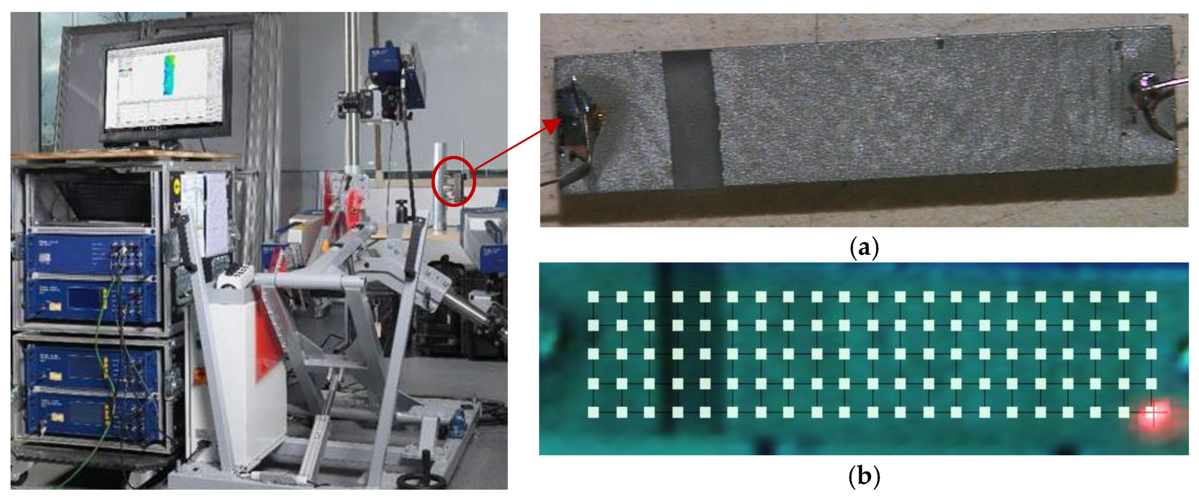
Y-cut GaPO4 rectangular piezoelectric elements of dimensions mentioned in Section 1 were obtained from Piezocryst GmbH. The elements were sputtered with platinum electrodes in both parallel and wrap-around electrode configurations. A 3D Polytec PSV-400 laser scanning vibrometer was used to measure the velocity and hence the displacement patterns occurring in the transducer at different frequencies. The experimental setup is shown in Figure 2 where a pulser receiver unit was used to excite the transducer with a broadband chirp input signal with a frequency range of 10–150 kHz similar to the frequency domain analysis described in Section 2.
4. Results and Conclusions
Through finite element analysis; with parallel electrode configuration, only the desired thickness shear mode of vibration (X) was dominant. However, with wrap-around electrodes, significant out of plane (Z) and lateral (Y) displacement were observed in the same frequency range. The simulated disparity in the dominant mode of vibration was experimentally validated by Vibrometry measurements. An example of the comparison of the displacement patterns is given in Figure 3.
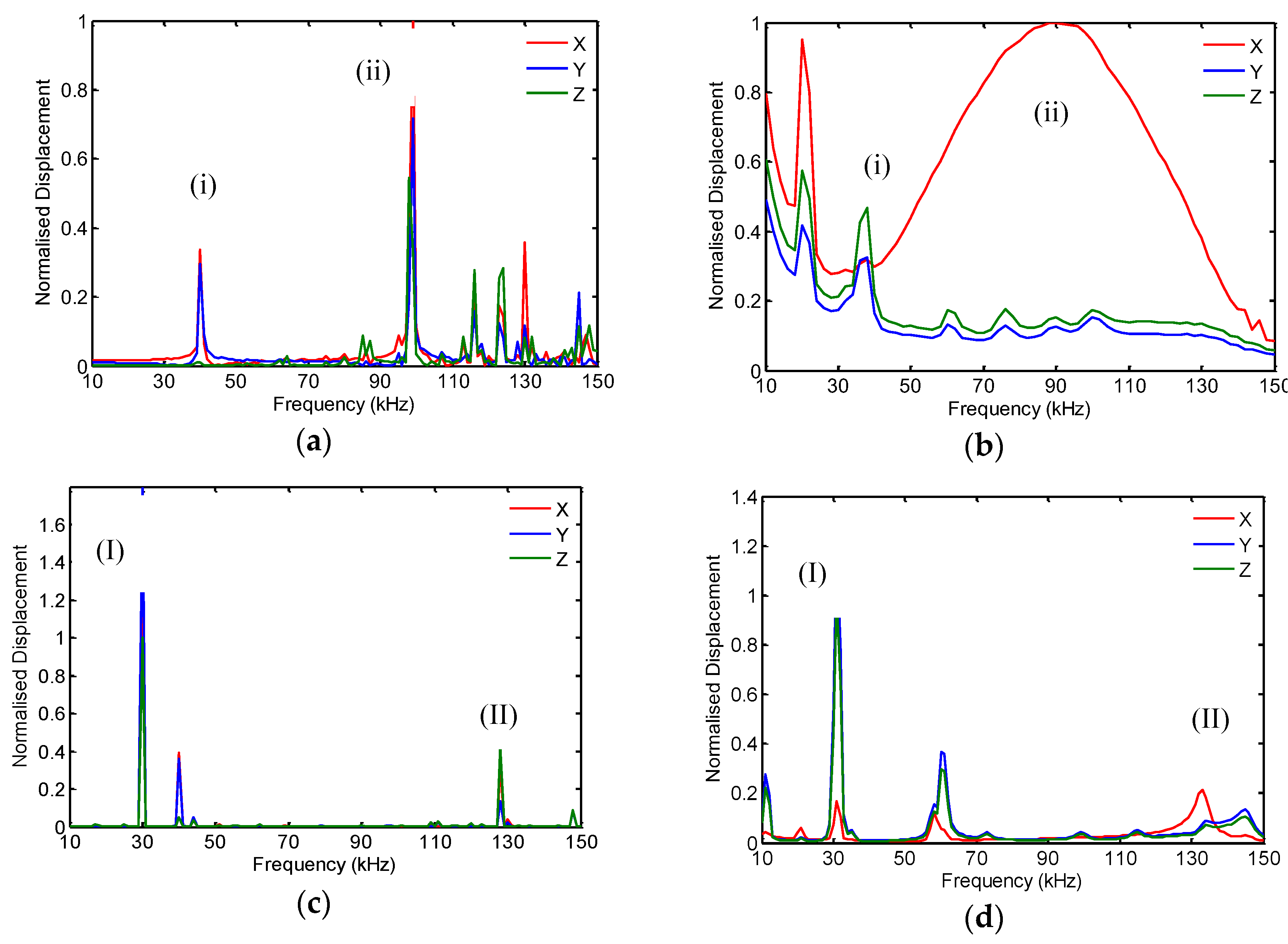
For a comparative study, the modeled and measured displacement amplitudes were normalized to their respective maxima. A good correlation between the resonance frequency and the principal displacement field was accomplished as shown in Figure 4, where the corresponding resonances are marked. The measured displacement response shows wider frequency bandwidth compared to the model especially in Figure 4b; indicative of damping induced by electrical connections. For now, the model can precisely predict the electromechanical resonances, displacement fields and hence mode of vibration and their dependence on the electrode configuration. Future refinements to the FEA model should include effects of mass loading from deposited electrode and electrical connection to achieve a better quantitative agreement with the measured frequency response.
The FEA model developed in this study provides a robust tool for designing HT GaPO4 transducer with a desired frequency response. The information about unwanted modes of vibration arising from electrode configuration can be used to implement appropriate transducer damping and/or signal processing techniques for compensation to achieve the desired transducer performance.
Conflicts of Interest
The authors declare no conflict of interest.
References
- Fritze, H. High-temperature piezoelectric crystals and devices. J. Electroceram. 2011, 26, 122–126. [Google Scholar] [CrossRef]
- Davulis, P.; Kosinski, J.A.; Da Cunha, M.P. GaPO4 stiffness and piezoelectric constants measurements using the combined thickness excitation and lateral field technique. In Proceedings of the 2006 IEEE International Frequency Control Symposium and Exposition, Miami, FL, USA, 4–7 June 2006; pp. 664–669. [Google Scholar]
- Cao, W.; Zhu, S.; Jiang, B. Analysis of shear modes in a piezoelectric vibrator. J. Appl. Phys. 1998, 83, 4415–4420. [Google Scholar] [CrossRef]
- Gerber, P.; Roelofs, A.; Kügeler, C.; Böttger, U.; Waser, R.; Prume, K. Effects of the top-electrode size on the piezoelectric properties (d33 and S) of lead zirconate titanate thin films. J. Appl. Phys. 2004, 96, 2800–2804. [Google Scholar] [CrossRef]
- Desilets, C.S.; Powell, D.J.; Abboud, N.; Wojcik, G.L. Effect of wraparound electrodes on ultrasonic array performance. In Proceedings of the 1998 IEEE Ultrasonics Symposium, Sendai, Japan, 5–8 October 1998; Volume 2, pp. 993–997. [Google Scholar]
- Krempl, P.; Schleinzer, G.; Wallno, W. Gallium phosphate, GaPO4: A new piezoelectric crystal material for high-temperature sensorics. Sens. Actuators A Phys. 1997, 61, 361–363. [Google Scholar] [CrossRef]
Figure 1.
Gallium phosphate piezoelectric wafer active sensors with: (a) Parallel electrode; (b) Wrap-around electrode configuration. The input terminal and ground electrodes are highlighted in red and black respectively.
Figure 1.
Gallium phosphate piezoelectric wafer active sensors with: (a) Parallel electrode; (b) Wrap-around electrode configuration. The input terminal and ground electrodes are highlighted in red and black respectively.
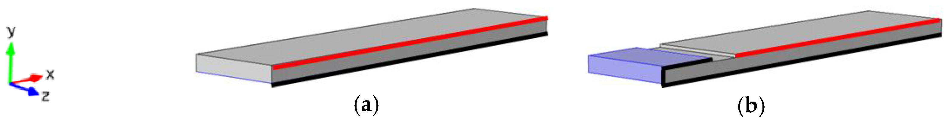
Figure 2.
3D-Laser Doppler Vibrometry experimental setup for measuring electrical displacement of (a) wraparound GaPO4 element with (b) scan points used for 3D measurements.
Figure 2.
3D-Laser Doppler Vibrometry experimental setup for measuring electrical displacement of (a) wraparound GaPO4 element with (b) scan points used for 3D measurements.

Figure 3.
Displacement pattern of Y-cut GaPO4 transducer at 100 kHz for parallel electrodes (a) modelled and (b) measured; and with wrap-around electrodes (c) modelled and (d) measured.
Figure 3.
Displacement pattern of Y-cut GaPO4 transducer at 100 kHz for parallel electrodes (a) modelled and (b) measured; and with wrap-around electrodes (c) modelled and (d) measured.
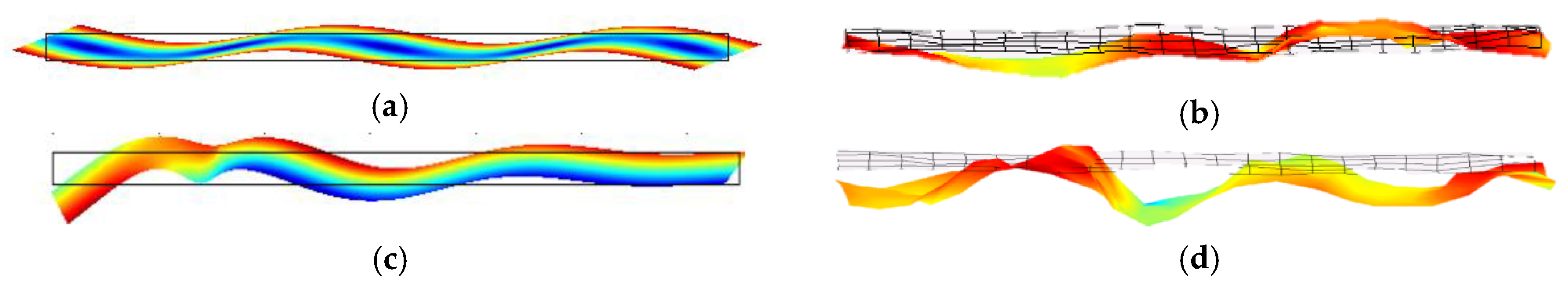
Figure 4.
Frequency response of Y-cut GaPO4 transducer with parallel electrodes (a) measured and (b) modelled compared (c) measured and (d) modelled results with wrap-around electrode. X, Y & Z are the displacement along length (shear), width (lateral) and thickness (out-of-plane) respectively.
Figure 4.
Frequency response of Y-cut GaPO4 transducer with parallel electrodes (a) measured and (b) modelled compared (c) measured and (d) modelled results with wrap-around electrode. X, Y & Z are the displacement along length (shear), width (lateral) and thickness (out-of-plane) respectively.
Publisher’s Note: MDPI stays neutral with regard to jurisdictional claims in published maps and institutional affiliations. |
© 2017 by the authors. Licensee MDPI, Basel, Switzerland. This article is an open access article distributed under the terms and conditions of the Creative Commons Attribution (CC BY) license (https://creativecommons.org/licenses/by/4.0/).
Share and Cite
MDPI and ACS Style
Dhutti, A.; Gan, T.-H.; Mohimi, A.; Balachandran, W.; Kanfoud, J. Effect of Electrode Configuration on High Temperature Thickness Shear Gallium Phosphate Transducer. Proceedings 2017, 1, 381. https://doi.org/10.3390/proceedings1040381
AMA Style
Dhutti A, Gan T-H, Mohimi A, Balachandran W, Kanfoud J. Effect of Electrode Configuration on High Temperature Thickness Shear Gallium Phosphate Transducer. Proceedings. 2017; 1(4):381. https://doi.org/10.3390/proceedings1040381
Chicago/Turabian StyleDhutti, Anurag, Tat-Hean Gan, Abbas Mohimi, Wamadeva Balachandran, and Jamil Kanfoud. 2017. "Effect of Electrode Configuration on High Temperature Thickness Shear Gallium Phosphate Transducer" Proceedings 1, no. 4: 381. https://doi.org/10.3390/proceedings1040381