A Miniaturized SPLITT System for On-Line Protein Separation †


1
Fondazione Bruno Kessler, Trento, Italy
2
Università di Trento, Trento, Italy
*
Author to whom correspondence should be addressed.
†
Presented at the Eurosensors 2017 Conference, Paris, France, 3–6 September 2017.
Proceedings 2017, 1(4), 527; https://doi.org/10.3390/proceedings1040527
Published: 25 August 2017
(This article belongs to the Proceedings of Proceedings of Eurosensors 2017, Paris, France, 3–6 September 2017)
Abstract
:The development of a microfluidic module for on-line protein separation is presented in this paper. The device is based on the SPLITT (Split flow Thin fractionation) technique and the separation of proteins is electrically driven by means of two platinum electrodes included in the structure of the microdevice. The microfluidic network is realized by means of a thin dry film structure, Ordyl SY 355, (thermo-compression lamination), laminated on three levels, which is patterned through a photolithographic technique. The device has been tested with a Bovine Serum Albumin (BSA) solution, through absorbance measurements with a spectrophotometer, with best achieved separation at the outlet of 40%, measured as relative concentration unbalance at output channels.
1. Introduction
Sample pre-treatment is usually envisaged before chemical and biological analysis. For example, if we want to detect contaminants in a complex matrix as milk, we must consider that the sample consists in a multiphase suspension of butterfat globules and water with dissolved carbohydrates and protein complexes. If we want a bio-sensor to perform a label free detection of target-contaminants in milk, interferents must be removed from the matrix. Proteins are an important part of these interferents, and their concentration needs to be reduced, in order to avoid fouling and consequently the inhibition of the sensor, or false positive results in the analysis.
In the framework of our research work, we have developed a microfluidic system that can be used as a pre-treatment device for the sample preparation in analytical microsystems, for instance coupled to bio-sensors.
2. Materials and Methods
The device that we have developed is based on the SPLITT theory, explained for the first time by J. C. Giddings [1] in 1985 and studied at microscale from early 2000’s.
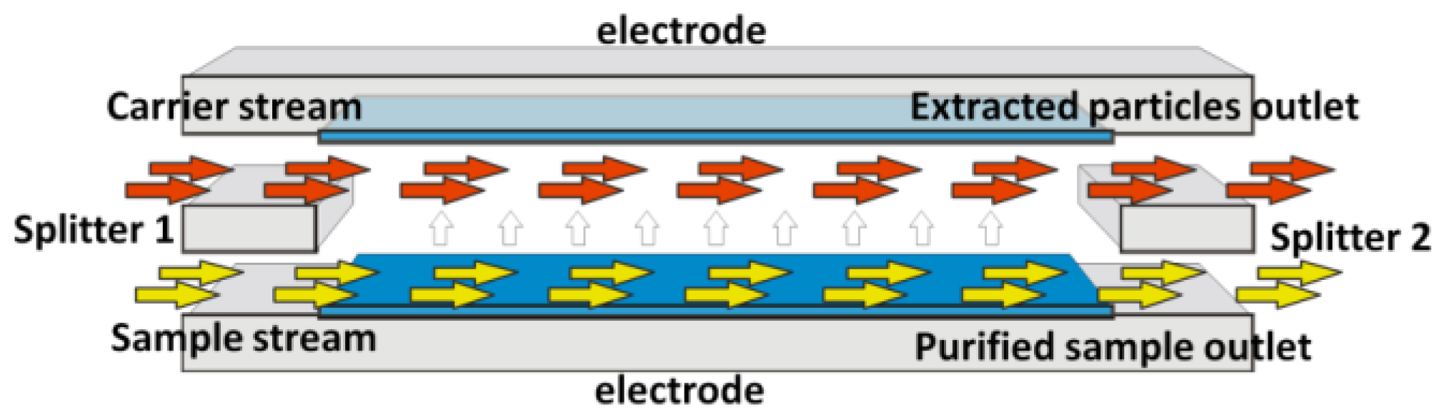
According to the SPLITT theory, two different fluids are introduced in the device by means of two inlets: a sample that we want to purify and a carrier solution. Under the action of a driving force, including gravitational, centrifugal, electrical and magnetic forces, the particles that we want to separate from the sample migrate towards the carrier stream and they are flushed out from a dedicated outlet (Figure 1). In the case of our device, a pulsed vertical electric field is imposed between the two electrodes; proteins are attracted by one of the electrodes and they move from the sample to the carrier stream. Therefore, the carrier solution (enriched in proteins) and the purified sample flow out from the separation microchannel through two different outlets. The sample and the carrier simultaneously pass through the microchannel on the top of each other, in laminar-flow conditions. Indeed, there are no turbulences in the microstructure, because of very low flow rate (50 microliters per minute) and, consequently, very low Reynolds number (<10).
Giddings also showed that the “splitting plane”, the separation between the two laminar streams is maintained by the presence of structures at the ends of the separation microchannel that are called splitters, which precisely separate the streams and prevent mixing (Figure 1). Thanks to a particular microfabrication technique, we have been able to realize the first dry film-based miniaturized SPLITT system equipped with a real splitting layer and suspended splitters. Narayanan et al. developed a microfabricated electrical SPLITT system, but with an “offset splitter” arrangement, by shifting the upper and the lower parts of the microfluidic microchannel [2]. Moreover, they tested the device with amino-coated particles ranging from 108 to 220 nm, while we evaluated the separation performance with a protein solution (BSA).
2.1. Fabrication
The electrophoretic module was fabricated (Figure 2) using three different layers of dry film resist (Ordyl 355SY by Elga Europe) subsequently laminated (thermo-compression lamination) on a silicon substrate. Starting from a simple microfabrication process on dry film already proposed in other studies as [3], we have realized a more complex structure providing a middle suspended layer (splitting layer) within the microfluidic network. After several tests we managed to set the best pressure/temperature condition for subsequent laminations and the proper development technique for the dry film after the exposition.
The first layer is laminated on a silicon wafer, then is exposed to UV and, after the development of the dry film, a second and a third layer are laminated on top of it, with a lower pressure and at lower temperature. The three lamination-exposition steps allow us to realize a microfluidic network patterned on the dry film through photolithography, including a splitter layer. The electrtic field for the separation is applied through two platinum electrodes that are deposited respectively (first step of the fabrication process) on the silicon substrate and on a glass cover that closes and seals the whole structure.
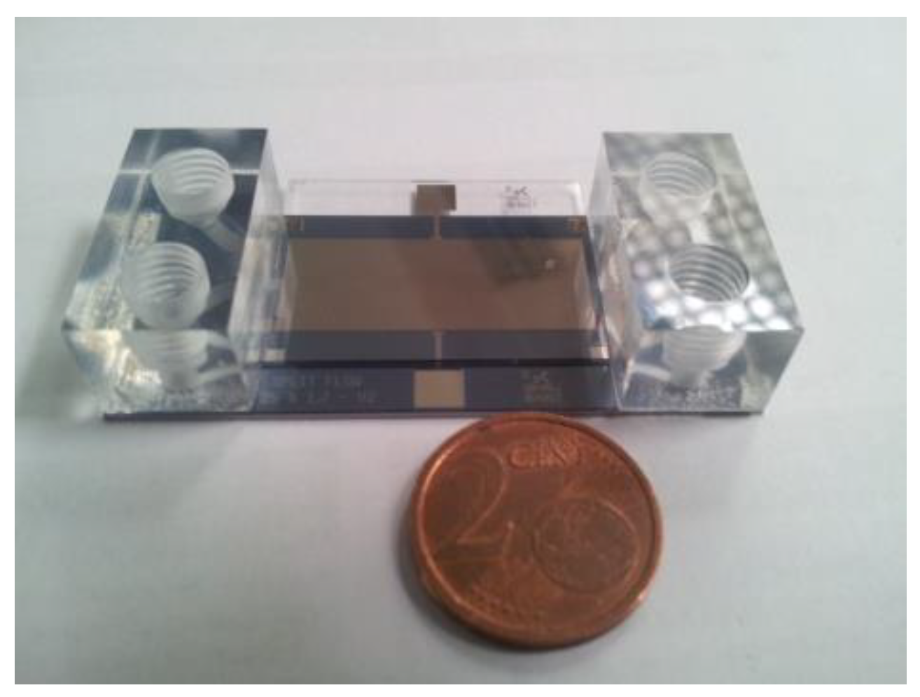
Details about the design of the separation channel and the microfluidic structure, taking into account the theory and the model of the electrically driven SPLITT, are shown in a previous work from our group [4]. Once the fabrication process is finished, the silicon wafer is diced into chips of 2.4 × 5.4 cm2, which are bonded together with the corresponding glass cover under vacuum using a wafer bonder. Two acrylic blocks are glued to the device inlets and outlets, as shown in Figure 3. An unexposed film (20 μm thick) of Ordyl 320SY was used as an adhesive layer. The acrylic blocks were positioned by means of a pick and place equipment and then attached to the device by thermo-compressive bonding.
2.2. Experimental Setup: Protein Separation Test
The electrically driven micro device has been tested with a BSA protein solution. It was attached on a PCB board through epoxy resin and the electrodes were connected to the pins of the PCB, by using gold ball-bonding. Two 10 mL syringe pumps, controlled from PC through a COM port, were used to drive the flowrate through specific shell commands. No carrier solution was used for this proof-of-concept test, but the same BSA solution was infused in the two inlets. The electric field used for the electrical SPLITT separation was generated through a DAQ system, controlled with a LabVIEW dedicated software, which allowed the setting of all the parameters (peak to peak potential, offset potential, wave form, frequency and duty cycle for square waves) of the signal. The voltage selected for the measurements was 5 V (peak to peak voltage) and the waveform was a square wave. The two outlets of the SPLITT system were connected to two 2 mL tubes through two Teflon capillaries (1/16″), and the absorbance of the samples was measured at 280 nm with a spectrophotometer, in order to evaluate the concentration of the protein in the two output streams of the device.
3. Results
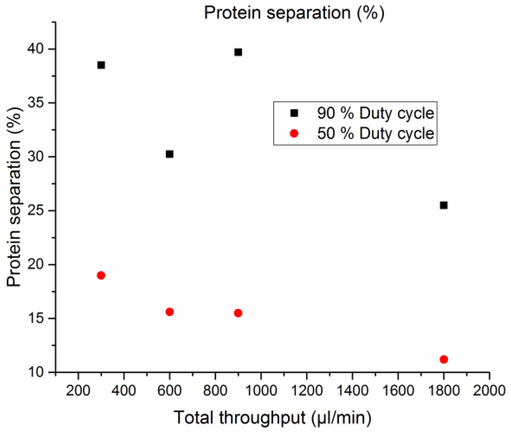
The results of separation tests are shown in Figure 4. Comparing the difference in protein content between the two outlets, we achieved up to 40% within the tested conditions. The difference of concentration is measured as relative unbalance at the output channels. As we can see, the best separation is achieved when the square-wave duty cycle is 90% (black dots), in comparison with the 50% duty cycle (red dots).
4. Discussion
The difference between the two data sets, collected by setting two different duty cycles is reasonable since, in the first case, the signal is “high” for a longer time. Moreover, we can notice that, if the test is performed in the range of 300–900 µL/min, the separation performances are stable, while if we drastically increase the flow rate, a performance reduction is observed, due to a shorter transition time in the separation channel. The phenomenon is particularly evident when the duty cycle is 50%. As we expected according to the design of the device and to the electrically driven SPLITT concept, the microelectrophoretic system responds to the variations of the driving force and the flow rate with different separation performances. After the first offline tests that have proved the effectiveness of the electrical SPLITT separation, we are now going to carry out continuous protein separation measurements, since the technology is focused on continuous flow applications.
Acknowledgments
This work has received funding from the European Union’s Seventh Framework Programme FP7-ICT-2013-10 under grant agreement No. 610580, STREP Project “SYMPHONY”.
Conflicts of Interest
The authors declare no conflict of interest. The founding sponsors had no role in the design of the study; in the collection, analyses, or interpretation of data; in the writing of the manuscript, and in the decision to publish the results.
References
- Giddings, J.C. A system based on split-flow lateral-transport thin (SPLITT) separation cells for rapid and continuous particle fractionation. Sep. Sci. Technol. 1985, 20, 749. [Google Scholar] [CrossRef]
- Narayanan, N.; Saldanha, A.; Gale, B.K. A microfabricated electrical SPLITT system. Lab Chip 2006, 6, 105–114. [Google Scholar] [CrossRef] [PubMed]
- Vulto, P.; Huesgen, T.; Albrecht, B.; Urban, G.A. A full-wafer fabrication process for glass microfluidic chips with integrated electroplated electrodes by direct bonding on dry film resist. J. Micromech. Microeng. 2009, 19, 077001. [Google Scholar] [CrossRef]
- Capuano, A.; Adami, A.; Mulloni, V.; Lorenzelli, L. Design of an electrophoretic module for protein separation. In Proceedings of the 2016 12th Conference on Ph.D. Research in Microelectronics and Electronics (PRIME), Lisbon, Portugal, 27–30 June 2016. [Google Scholar] [CrossRef]
Figure 1.
SPLITT system scheme. The splitters play a key role to maintain the “splitting plane”.

Figure 2.
Fabrication process. Sequence of steps from the patterning of the electrodes to the glass cover bonding.
Figure 2.
Fabrication process. Sequence of steps from the patterning of the electrodes to the glass cover bonding.

Figure 3.
The device equipped with the two acrylic connectors.

Figure 4.
Separation test. Protein separation performances depends on the duty cycle of the square wave signal and on the flow rate.
Figure 4.
Separation test. Protein separation performances depends on the duty cycle of the square wave signal and on the flow rate.

Publisher’s Note: MDPI stays neutral with regard to jurisdictional claims in published maps and institutional affiliations. |
© 2017 by the authors. Licensee MDPI, Basel, Switzerland. This article is an open access article distributed under the terms and conditions of the Creative Commons Attribution (CC BY) license (https://creativecommons.org/licenses/by/4.0/).
Share and Cite
MDPI and ACS Style
Capuano, A.; Adami, A.; Mulloni, V.; Lorenzelli, L. A Miniaturized SPLITT System for On-Line Protein Separation. Proceedings 2017, 1, 527. https://doi.org/10.3390/proceedings1040527
AMA Style
Capuano A, Adami A, Mulloni V, Lorenzelli L. A Miniaturized SPLITT System for On-Line Protein Separation. Proceedings. 2017; 1(4):527. https://doi.org/10.3390/proceedings1040527
Chicago/Turabian StyleCapuano, Andrea, Andrea Adami, Viviana Mulloni, and Leandro Lorenzelli. 2017. "A Miniaturized SPLITT System for On-Line Protein Separation" Proceedings 1, no. 4: 527. https://doi.org/10.3390/proceedings1040527