In-Vivo Implantable Sensor System for Measuring Bladder Wall Movements †


1
Department of Electrical Engineering, MICAS, KU Leuven, Leuven, Belgium
2
Laboratory of Experimental Urology, KU Leuven, Leuven, Belgium
*
Author to whom correspondence should be addressed.
†
Presented at the Eurosensors 2017 Conference, Paris, France, 3–6 September 2017.
Proceedings 2017, 1(4), 566; https://doi.org/10.3390/proceedings1040566
Published: 17 August 2017
(This article belongs to the Proceedings of Proceedings of Eurosensors 2017, Paris, France, 3–6 September 2017)
Abstract
:The design and implementation of a medical implantable device for bladder monitoring is presented. A network of accelerometers is to be implanted in-between the outside bladder muscle and the mucous membrane. A pressure sensor is also implanted in this submucosal layer to obtain intraluminal pressure readings. The sensor system is powered by an implanted battery and provides a wireless communication link for data and control. A smart measurement protocol allows the system to be operational for several weeks. The sensors are mounted on a flexible printed circuit board that can be elongated up to 250%, to accommodate the natural stretching of the bladder organ tissue during filling.
1. Introduction
Hundreds of millions of people worldwide suffer daily from medical conditions affecting the bladder and the sensation of urgency, such as overactive bladder syndrome (OAB), urinary incontinence (UI) and lower urinary tract symptoms (LUTS). Continuous monitoring of physiological parameters of the urinary bladder can provide physicians with valuable new information about the inner operation of the bladder and the conditions that cause such bladder dysfunctions. More specifically, the possible relation between bladder muscle contractions and the sensation of urgency, is still unknown in the medical field. One theory predicts the existence of an autonomous function of the bladder [1], where bladder wall contractions play a role in sensing bladder volume. To measure bladder function, conventional cystometry methods are used, which consist of pressure sensing catheters and flow measurements. However, measuring only one pressure point can impossibly present the full picture of localized bladder wall movements, nor can it detect small vibrations of the detrusor muscle. Previously, a single high-precision accelerometer was placed on the bladder of a sedated, male rat during in vivo tests, and demonstrated the merits of inertial sensing [2,3]. In [3] also cadaver tests were performed to show the feasibility of submucosal implantation of the sensors. In order to measure bladder activity more closely related to that of humans, efforts are directed towards the bladder of Göttingen minipigs. This work presents the design choices to make a fully implanted system for measuring accelerations and pressure on multiple locations of the bladder of these pigs, while they are awake and naturally void their bladders.
2. System Design
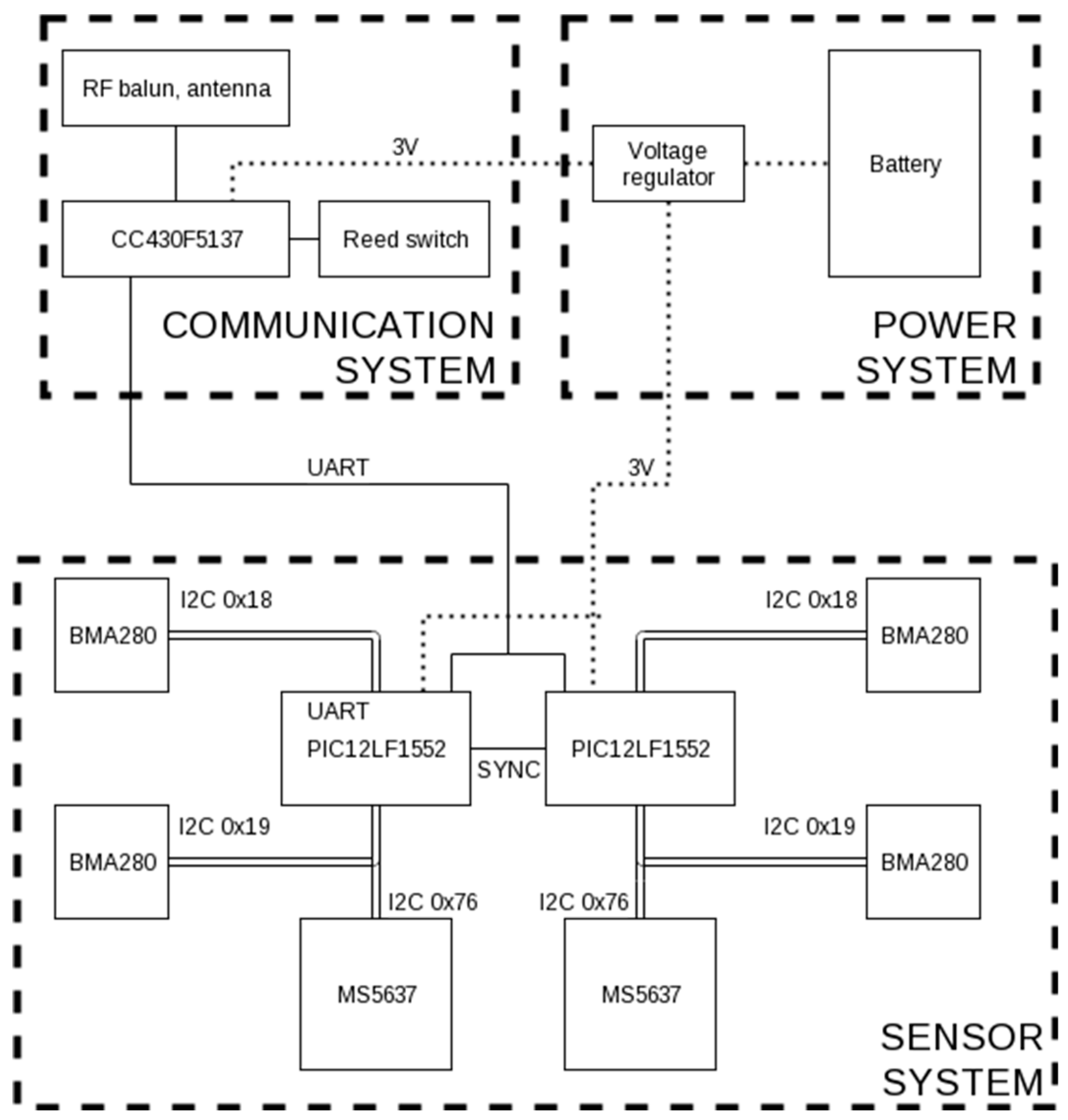
The implantable system consists of three subsystems: the sensor system, the wireless communication, and the power supply system. The sensor system was designed to continuously sample four accelerometers (Bosh Sensortec BMA280) and two pressure sensors (TE Connectivity MS5637) with a sample frequency of 50 Hz. There are two 8-bit microcontrollers (Microchip PIC12LF1552) that take turns reading one sample of each of the three sensors. They are each connected to the communication system and transmitting the data over a shared UART connection to it. The connections between microcontrollers and sensors are depicted in the block diagram in Figure 1.
The communication system is the brain of the implant. Its task is to take the UART data from the sensor system and transmit it outside of the body to an external receiver. This is achieved using a Texas Instruments CC430F5137 microcontroller, using the integrated 433 MHz RF transceiver. A single-wire quarter-wavelength antenna was chosen. A full system reset can be triggered by a reed switch, activated by an external magnet.
The power system consists of a 700 mAh thin-cell LiPo battery and a voltage regulator (Texas Instruments TPS62740). The integrated load switch of the voltage regulator is used to toggle power to the sensor system when required, and is controlled by the communication system.
The operating system of the communication system can run in three different modes. When no measurements are taken, the whole implant is in a very-low power mode. Periodically, after a configurable sleep duration, the RF link listens for configuration commands from the external transceiver. Power consumption of the listening mode is high, so the occurrence and duration of this mode are strongly limited. The third mode is actively sampling the sensors and sending data over the RF link. The durations of all three modes can be configured during listening mode. Table 1 shows measurement results of the current consumption of the system during the different modes. If the implant wakes up to listen for incoming commands once every hour for a duration of 60 s, a battery of 700 mAh can power the system in sleep mode for more than 1000 h or in continuous sampling mode for 100 h. The physician can still communicate with the implant once per hour, or whenever required by using the reed switch to reset the system.
The sensor system is designed as a 3-armed structure with inertial sensors at the distal ends, and one accelerometer in the central part. One of the arms contains a pressure sensor on the backside, and a second pressure sensor is used to measure abdominal pressure for reference. The communication system and power system are made on a regular PCB that has the same size as the battery. The two assembled systems are depicted in Figure 2a.
The intended location of the sensors on the bladder is shown in Figure 2b, along with the communicating system which is implanted in a fat pocket under the skin of the abdomen. The sensor system is fabricated in a way so that it can accommodate the periodic stretching of the bladder muscle during filling and voiding, up to 250% elongation, without any noticeable obstruction force. In order to assess the motion of the bladder wall, the sensors have to be attached to the detrusor muscle. Outside fixation onto the bladder wall is rather cumbersome, and, moreover, does not allow to measure pressure the internal bladder pressure. Instead, a submucosal location for the sensors is used between the detrusor and the mucosa. This ensures a good fixation to a specific location of the bladder, and submucosal pressure readings have been shown to correlate well to intraluminal pressure [4].
3. Implantation Procedure
After anesthesia and insertion of a catheter into the bladder, an incision is made in the lower abdomen, after which the bladder is exposed. The central part of the sensor system is attached to the detrusor with stiches through six holes in the flex print. Then, three cuts are made into the detrusor without puncturing the mucosa. Each distal end of the arms of the sensor system is placed in the created pocket, each and the detrusor is stitched. After closing the peritoneum, a pocket is made into the fat of the abdomen, and the communication system with battery is placed inside. Figure 3 depicts several steps taken during a preliminary implantation test. The testing device was a functioning communication system with dummy flexible printed circuit boards similar to the present sensor system. The test system could successfully transmit to an external base station. The dummy system was explanted from the bladder after five weeks and the animal made a full recovery.
4. Results and Conclusions
A fully implantable system was designed and fabricated to measure bladder parameters in Göttingen minipigs. The system can assess acceleration data in four discrete locations of the bladder and read pressure levels inside the submucosal pouch. It can be remotely activated to measure for specific durations and has an autonomy of up to several hundreds of hours depending on the requirements of measurement duration and frequency. Although no actual acceleration measurements are performed yet, preliminary tests have proven the functionality of the communication system and the implantation method, hinting for this to be a promising method of assessing bladder wall activity.
Ethical Statements
The animal experiments in this work were evaluated and approved by the Animal Ethics Committee (project number 172/2015) of the KU Leuven in compliance with all applicable national and international guidelines.
Acknowledgments
The research leading to these results has received funding from the European Research Council under the European Union’s Seventh Framework Programme (FP7/2007-2013)/ERC grant agreement No. 340931.
Conflicts of Interest
The authors declare no conflict of interest. The funding sponsors had no role in the design of the study; in the collection, analyses, or interpretation of data; in the writing of the manuscript, and in the decision to publish the results.
References
- Gillespie, J.I. The autonomous bladder: A view of the origin of bladder overactivity and sensory urge. BJU Int. 2004, 93, 478–483. [Google Scholar] [CrossRef] [PubMed]
- Weydts, T.; Deruyver, Y.; Brancato, L.; Dewulf, K.; Soebadi, M.A.; Weyne, E.; De Ridder, D.; Puers, R. Developing a long-term implantable system to accurately measure real-time bladder wall movements: A feasibility study in the rat. Eur. Urol. Suppl. 2016, 15, e348. [Google Scholar] [CrossRef]
- Brancato, L.; Weydts, T.; Soebadi, M.A.; De Ridder, D.; Puers, R. Submucosal exploration of EMG and physiological parameters in the bladder wall. Proc. Eurosens. 2017. accepted. [Google Scholar]
- Majerus, S.J.; Fletter, P.C.; Ferry, E.K.; Zhu, H.; Gustafson, K.J.; Damaser, M.S. Suburothelial Bladder Contraction Detection with Implanted Pressure Sensor. PLoS ONE 2017, 12, e0168375. [Google Scholar] [CrossRef] [PubMed]
Figure 1.
Block diagram of the system, consisting of the three subsystems.

Figure 2.
The physical design of the measurement system. (a) The fabricated system. Left: the flexible sensor system with three sensing arms. Right: the subcutaneous wireless communicating system. Both subsystems are depicted, yet without final biocompatible packaging; (b) The intended way of implantation. Only the three tips of the flexible sensing system are implanted submucosally, while the rest of the sensor system is on the outside of the bladder wall. The battery and communication system is implanted subcutaneously.

Figure 3.
Several preliminary results showing feasibility of implantation procedure on a Göttingen minipig. (a) Fabrication of a pocket in the fat tissue for locating the communication system; (b) Insertion of the communication system into the fat pocket (c) Submucosal position of a flexible dummy PCB on the bladder, after 5 weeks of implantation.


Table 1.
Current consumption in the different operation modes, at a supply voltage of 3.0 V.
| Operation Mode | Current Consumption |
|---|---|
| Listening mode | 16 mA |
| Sampling & transmitting mode | 6.5 mA |
| Low-power mode | 0.30 mA |
Publisher’s Note: MDPI stays neutral with regard to jurisdictional claims in published maps and institutional affiliations. |
© 2017 by the authors. Licensee MDPI, Basel, Switzerland. This article is an open access article distributed under the terms and conditions of the Creative Commons Attribution (CC BY) license (https://creativecommons.org/licenses/by/4.0/).
Share and Cite
MDPI and ACS Style
Weydts, T.; Brancato, L.; Soebadi, M.A.; Ridder, D.D.; Puers, R. In-Vivo Implantable Sensor System for Measuring Bladder Wall Movements. Proceedings 2017, 1, 566. https://doi.org/10.3390/proceedings1040566
AMA Style
Weydts T, Brancato L, Soebadi MA, Ridder DD, Puers R. In-Vivo Implantable Sensor System for Measuring Bladder Wall Movements. Proceedings. 2017; 1(4):566. https://doi.org/10.3390/proceedings1040566
Chicago/Turabian StyleWeydts, Tristan, Luigi Brancato, Mohammad A. Soebadi, Dirk De Ridder, and Robert Puers. 2017. "In-Vivo Implantable Sensor System for Measuring Bladder Wall Movements" Proceedings 1, no. 4: 566. https://doi.org/10.3390/proceedings1040566