The Testing of a Sprayed Bentonite Sealing Layer †


1
Centre of Experimental Geotechnics, Faculty of Civil Engineering, Czech Technical University in Prague, Prague 16629, Czech Republic
2
Department of Irrigation, Drainage and Landscape Engineering, Faculty of Civil Engineering, Czech Technical University in Prague, Prague 16629, Czech Republic
*
Author to whom correspondence should be addressed.
†
Presented at the 3rd EWaS International Conference on “Insights on the Water-Energy-Food Nexus”, Lefkada Island, Greece, 27–30 June 2018.
Proceedings 2018, 2(11), 666; https://doi.org/10.3390/proceedings2110666
Published: 9 August 2018
(This article belongs to the Proceedings of EWaS3 2018)
Abstract
:A physical model of a pond dam was constructed at the Czech Technical University for the conducting of various related experiments including the application of sprayed bentonite. Importantly, the model allowed for the real-scale testing of a bentonite sealing layer which was applied in such a way as to provide protection against leakages along the concrete wall. The model of the dam will be carefully monitored so as to identify potential leakages once the reservoir of the experimental dam has been filled with water. The particle size distribution of the bentonite material and initial testing indicated that granulated “Bentonite 75” exhibits very good properties for the given purpose.
1. Introduction
Carp-breeding ponds are found throughout the Czech Republic, and some of these unique structures are as much as one thousand years old. It is clear that, as with all building structures, the dams of such ponds will become damaged over time resulting in undesirable leakages which may, in extreme cases, lead to a breach in the dam. Such ponds make up an important part of the Czech landscape and play a significant role in terms of water management. Thus, it is particularly important that such dams be carefully maintained and that leakages, which may negatively affect their overall geotechnical stability, be prevented.
Bentonite exhibits excellent sealing properties which are enhanced by the increasing dry density of the material. Several methods exist aimed at the sealing of pond dams using bentonite, i.e. the Blanket, Mixed Blanket and the Sprinkle methods. Sprayed bentonite technology is a relatively new technique which was developed primarily for use in deep geological repositories for the disposal of radioactive waste. Research focusing on the application of sprayed bentonite for the sealing of pond dams has been underway at the Czech Technical University in Prague (CTU) since 2016. The sprayed bentonite method has its origins in sprayed concrete technology and, of the two technological procedures available with concern to this method, i.e. the dry and wet processes, the dry process was selected for the sprayed bentonite sealing layer of pond dams; Czech calcium-magnesium bentonite “Bentonite 75” was chosen as the most appropriate material for this purpose.
A physical model of a pond dam was constructed at the CTU which allowed for the real-scale testing of the bentonite sealing layer.
2. Construction of the Physical Model
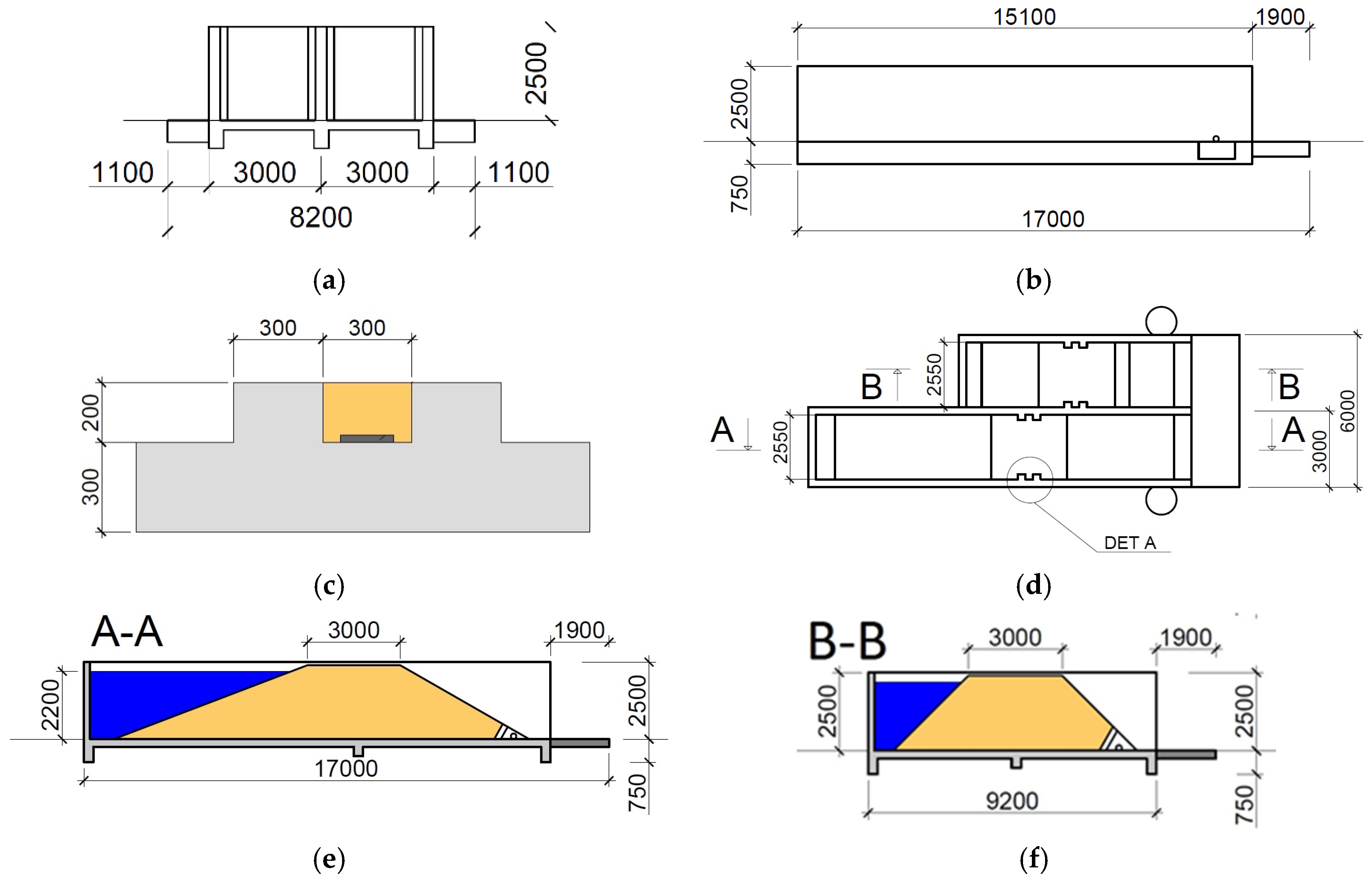
The physical model consists of two sections each with a width of 3 m and a total length of 17 m. Both sections are bounded by rear and side walls 300 mm thick and include models of pond dams constructed according to the technology historically employed for such ponds. The models were designed both for the assessment of the durability of the methods historically used for the reinforcement of dam bodies, and the experimental testing of the technical options available for the repair of damaged dam structures employing different types of clay mixtures and applications. The physical model allowed for the testing of both surface and internal faults. Moreover, the dam models were designed so as to enable the installation of a comprehensive monitoring system for the measurement of, particularly, ground leakage and the geotechnical state of the dam. The functional model was constructed from concrete blocks reinforced according to a calculation aimed at maintaining the water column pressure. A double rib was constructed in the center of the dams for reinforcement purposes and a space was created between the ribs for the application of the sprayed bentonite sealing material. It was assumed that the sprayed clay sealing material would act to reduce the incidence of potential leaks along the concrete walls of the physical model. Figure 1 provides cross-sectional diagrams of the physical model. Figure 1 shows: (a) view from the front of the model; (b) side view; (c) detail A of the two ribs between which a bentonite layer was sprayed along with a hydraulic pressure monitoring sensor; (d) ground plan showing cuts A-A and B-B and detail A; (e) cut A-A—showing a cut through the second dam (inclines 1:2 and 1:3); (f) cut B-B—showing a cut through the first dam (inclines 1:1).
3. Spray Testing Materials
Bentonite clay has excellent sealing properties thanks to its low hydraulic conductivity and swelling pressure [1]. The properties required of the sealing bentonite layer used for such ponds are not specified in the literature; nevertheless, it is known that hydraulic conductivity and swelling pressure make up the two key geotechnical parameters, the required values of which for the testing of the sprayed sealing layer in this project were determined at:
- Hydraulic conductivity k < 10−11 m/s,
- Swelling pressure σsw > 0.5 MPa
3.1. Bentonite 75
Czech raw Bentonite 75 (B75) in powder form was selected for testing purposes. B75 is a Czech calcium-magnesium bentonite with a montmorillonite content of around 75% [2] extracted from the Cerny vrch deposit (north-western region of the Czech Republic). The bentonite was supplied by the KERAMOST, Plc. (Žatecká 1899/25; CZ 434 30; Most, The Czech Republic) [3] and consists of an industrially-produced material which has been dried, crushed and sieved.
The basic geotechnical properties of B75 bentonite (average values obtained from the Centre of Experimental Geotechnics database and from [4,5,6] are:
- Water content at the liquid limit 229%
- Water content at the plastic limit 65%
- Specific density 2.82 g/cm3
- Hydraulic conductivity at 1.5 g/cm3 5.10−12 m/s
- Swelling pressure at 1.5 g/m3 3 MPa
- Thermal conductivity at 1.45 g/cm3 and at water content 7.5% 0.4 W/m/K
- Swell index (volume of 2 g of B75 following swelling in water) 22 ml/2g
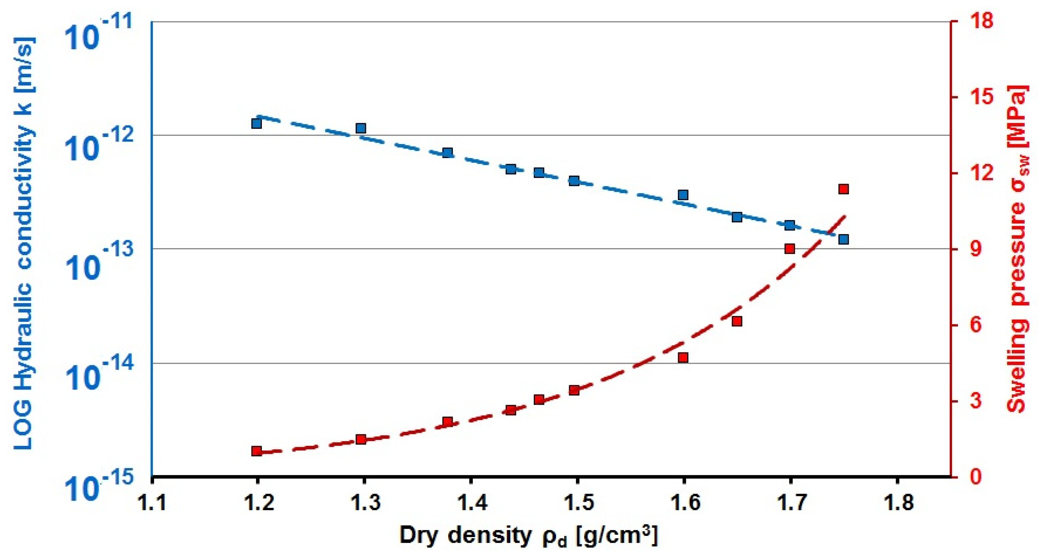
Figure 2 illustrates the sealing properties of B75 (hydraulic conductivity, swelling pressure), which have been proved to be highly dependent on the compaction level (dry density).
3.2. Granulated Bentonite 75
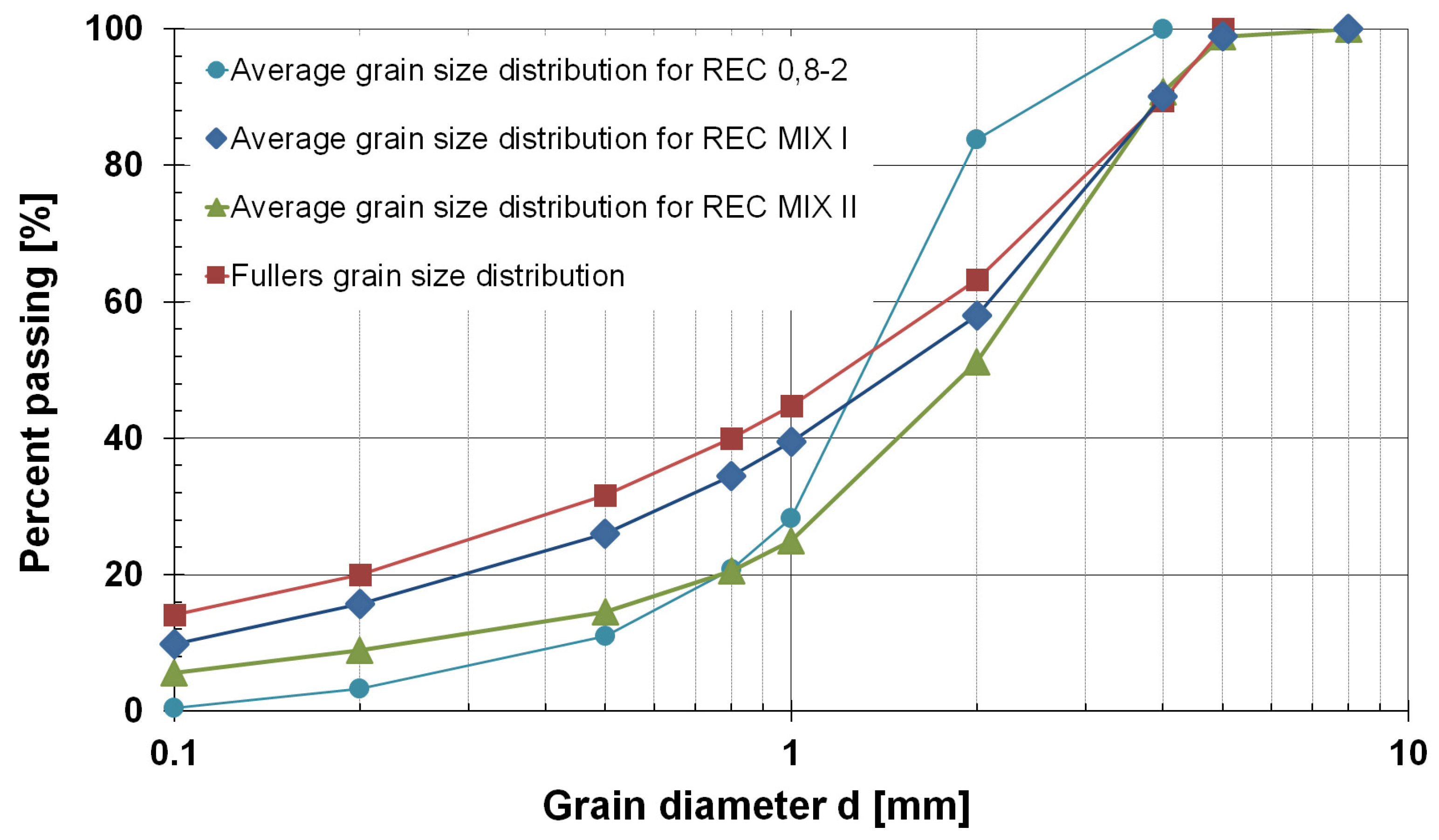
The industrially-produced B75 raw material was selected for testing purposes. The material featured differing grain size distributions depending on the technology employed at the production facility. The grain size distribution of the test mixtures was compared with the Fullers grain size distribution given by the Fuller equation, which defines the degree of granulation at which the content of voids is minimized:
where yi is the percentage passing through the given sieve size, in %; n is the power curve parameter (0.5 [7] or 0.33 [8]); in this study n = 0.5; Dmax is the maximum size aggregate in the mixture, in mm
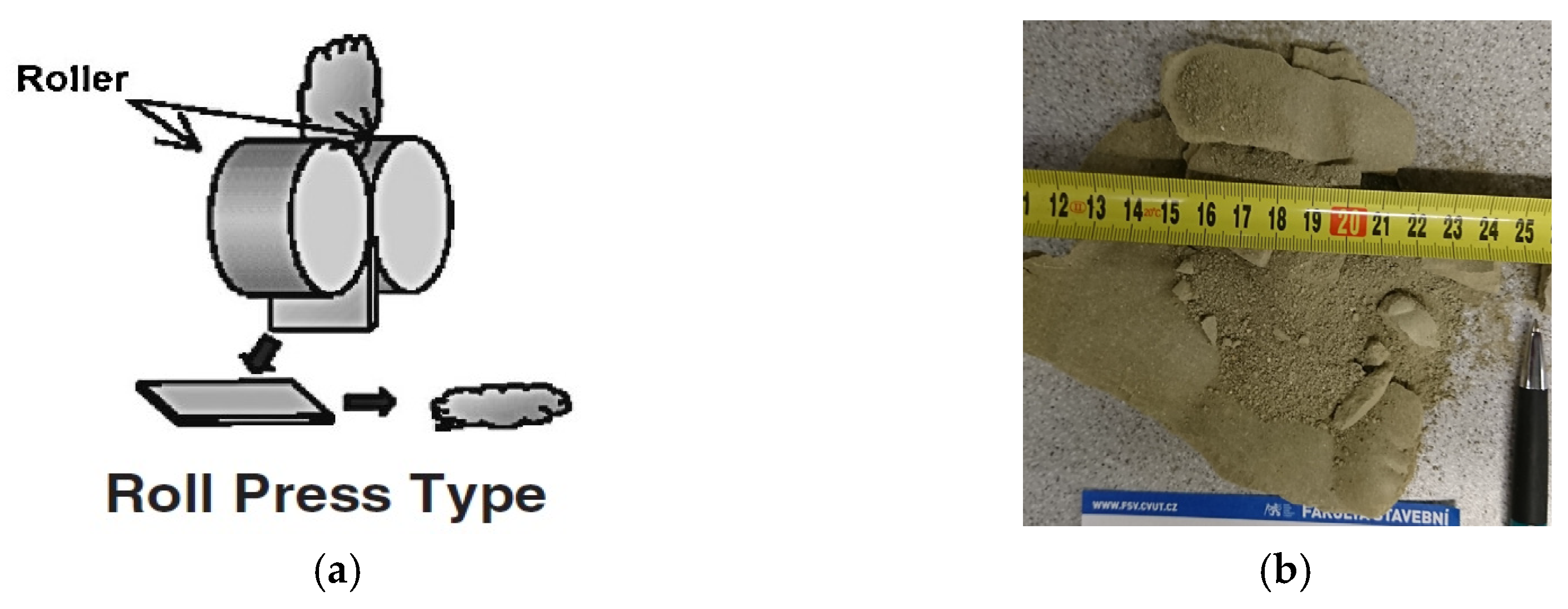
Granulated bentonite is produced via the compaction of the residue material employing roller press technology (see Figure 3a). Following compression and drying, the material (labeled REC) is crushed. Prior to the crushing process, the pellets are plate-shaped with a length of up to 15 cm (see Figure 3b). Following crushing, the bentonite molding plates are characterized by a maximum edge size of 5 cm. Industrial fractionation is achieved through the use of sieves, via which it is possible to obtain a bentonite pulp with fragments in the range of, for example, from 0.8 to 2 mm up to in excess of 5 mm.
3.2.1. Existing Granulated Bentonite 75 Mixture
Several different mixtures were tested for research purposes, which resulted in the selection of B75 REC 0.8-2 as exhibiting the ideal level of compaction following spraying. This mixture was then employed as the material to be used in the initial tests performed in order to determine the design of the new mixtures. Figure 4 shows the grain size distribution curves for B75 REC 0.8-2. The values provided by the producer (Keramost Ltd.) which follow the name of the bentonite material indicate the approximate minimum grain size diameter (0.8 mm) and the maximum grain size diameter (2 mm); however, this information proved to be inaccurate, as shown by the grain size distribution curve in Figure 4. Some grains had a diameter in excess of 2 mm, while others had dimensions below 0.8 mm.
3.2.2. New Granulated Mixtures Produced from Bentonite 75
Since the bentonite mixtures obtained from the producer were “not ideal” for spray application purposes, it was deemed necessary to develop more suitable mixtures from the original material. The aim was to develop new mixtures which would comply with the Fullers equation for the “ideal” grain size distribution curve. Consequently, two new mixtures (B75 REC MIX I (Figure 5a) and B75 REC MIX II) were designed which met the Fullers grain size distribution requirements (see the graph in Figure 4). Preparations were then made for the industrial production of the new mixtures in cooperation with the relevant research partners. After further testing, B75 REC MIX I finally proved to exhibit the best match with the grain size distribution curve given by the Fullers equation (Figure 4).
4. Spray Technology
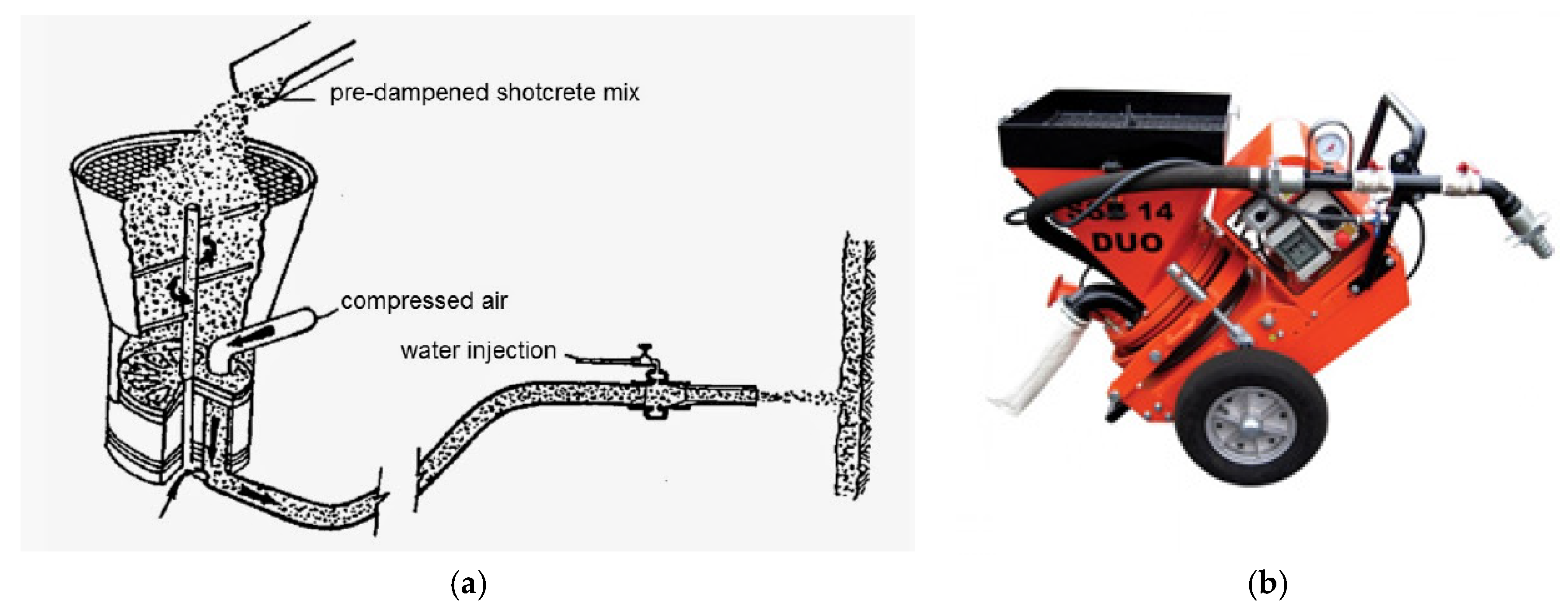
Sprayed clay technology is based on that of sprayed concrete, for the application of which two technological procedures are employed, i.e. the dry and wet methods [10]. Following the detailed research of the two methods, it was decided that dry spraying technology [11] would be used for the research of sprayed clay at the Centre of Experimental Geotechnics. The machine assembly used for spraying (the spraying assembly) is composed of five parts, the first of which consists of the compressor, with respect to which the amount of air supplied to the transport pipe (power) makes up a crucial factor. Moreover, the output rate was also found to influence the density of the material following injection. The main part of the spraying assembly consists of the so-called dosing machine (the SSB 14 DUO spraying machine, manufacturer Filamos Plc. (Žatecká 1899/25; CZ 434 30; Most, The Czech Republic); [12]). A single-sided dosing machine is employed with respect to sprayed clays. The spraying mixture is poured into a hopper from which it feeds into a rotor which serves to blend the mixture prior to its entering the compressed air stream. The amount of material injected can be controlled by the rotor rotation speed. The other parts of the equipment consist of the transport hoses, two types of which are used for the application of the material. The first type is used to transport compressed air from the compressor to the SSB 14 DUO machine (Figure 6a Scheme of the dry mix spraying machine [1] and (b) the SSB 14 DUO spraying machine produced by Filamos Ltd. [2].), while the second type is used to transport the compressed air mixture and the applied material from the machine to the spray nozzle. Via the careful selection of the diameter of the second hose, the resulting kinetic energy of the spray can be controlled and, provided the hose is of sufficient length, the uniform mixing of the feed material with the compressed air stream is ensured. The nozzle, which mixes water with a mixture of air and spray material, makes up the final component of the spray transport equipment. Due to initial problems with the clogging up of the nozzle, a new nozzle was designed at the CEG which eliminated problems associated with the mixing of the water and the spray material. The mixing water is conveyed to the nozzle by a hose fitted with a flowmeter which allows for the precise control of water inflow.
5. Material Requirements Following Spraying and the Results
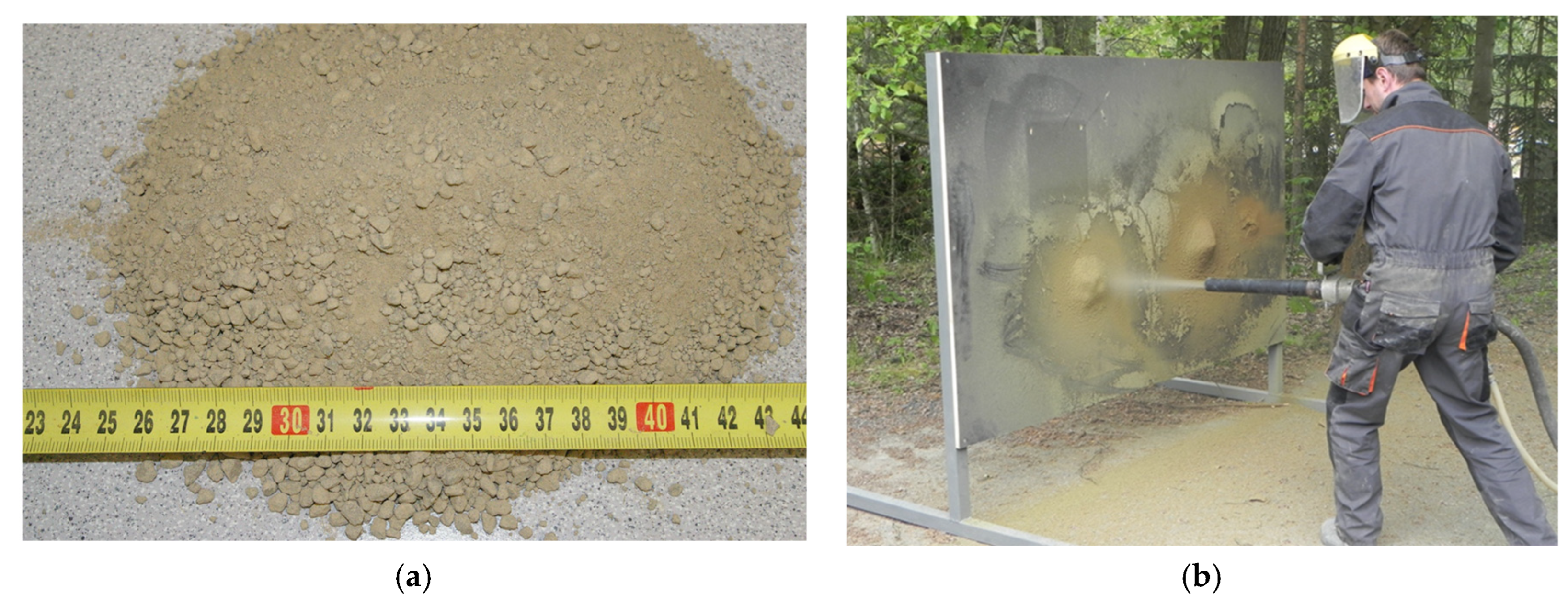
The main material requirements are related to the technology and the ideal compaction of the material (dry density) following spraying. The research of the materials focused on obtaining a sufficiently high dry density level and the limiting of the “fallout” of the sprayed material and the consequent problem of excessive dust. As for the technology, the adding of water in the nozzle played a key role in the spraying process, i.e., with respect to the amount thereof (rate to the mass of the applied clay), pressure and the distribution inside the clay material.
Since the main indicator of the success of the sprayed clay method consists of the level of dry density, this value must be evaluated following each spray test (Figure 5b). Dry density is calculated from the mass water content and density of samples extracted from the sprayed layer. The samples must be adjusted for the determination of volume by means of common laboratory methods (e.g., measurement in water based on the Archimedes principle). The results of the spray tests are shown in the graph in Figure 7.
6. Field Testing
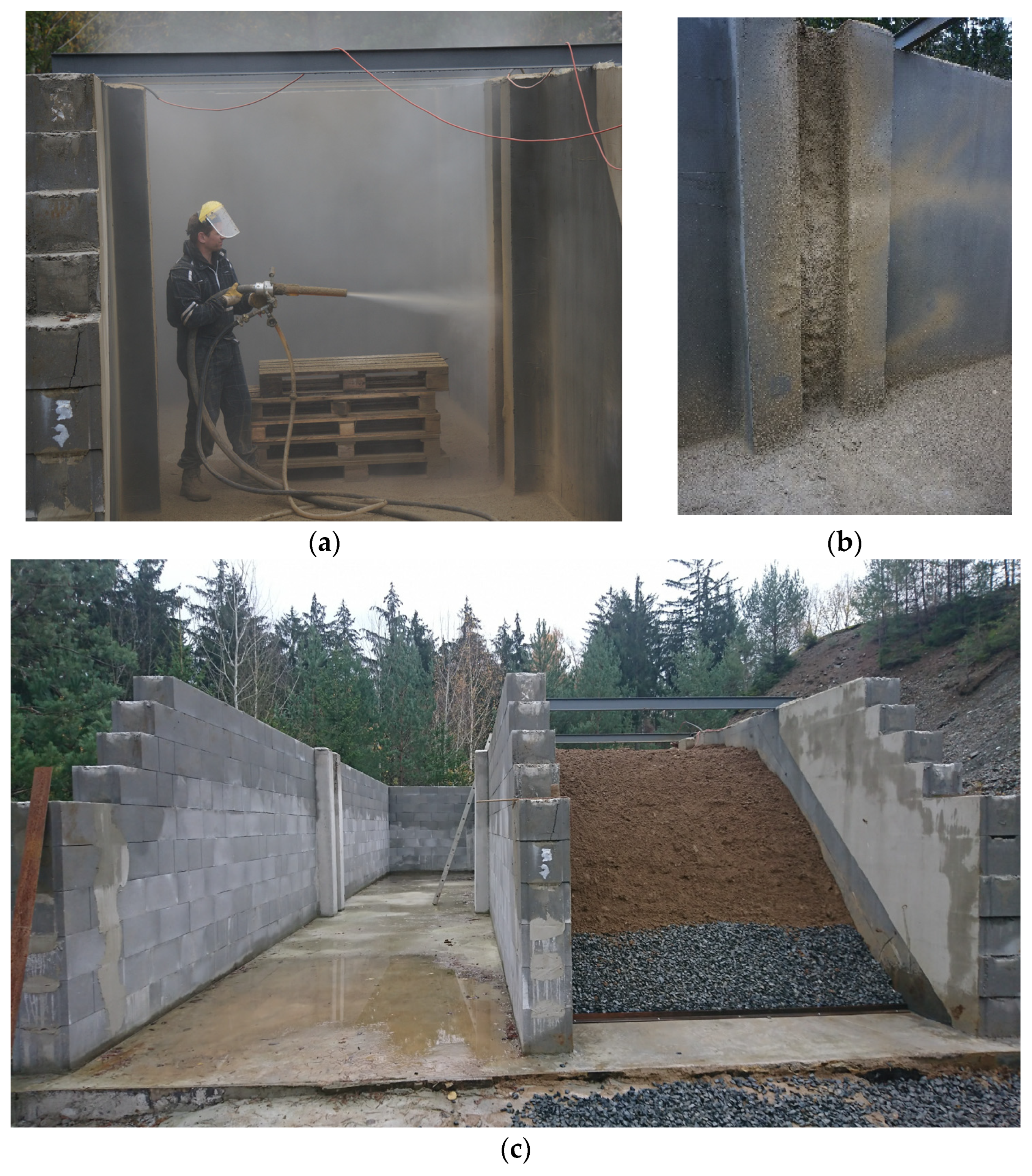
The first spray field test was conducted in connection with the construction of the physical dam models. The REC MIX I material was sprayed onto two concrete walls so as to prevent the flow of water between the soil of the dam and the main concrete walls of the physical model (Figure 8b). The second sprayed layer was applied to the bottom of the physical model in order to prevent the flow of water between the soil of the dam and the concrete bottom of the model.
7. Results and Discussion
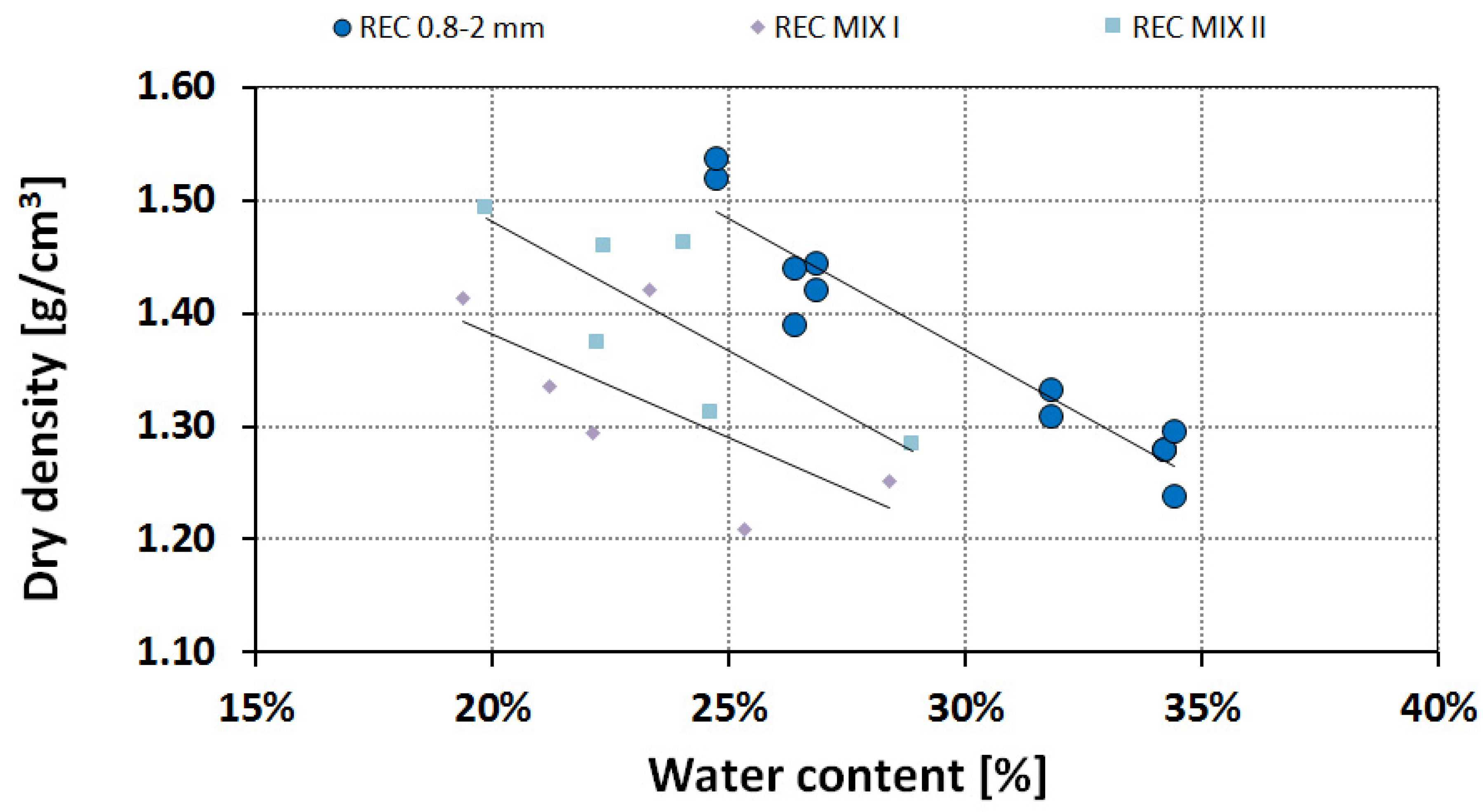
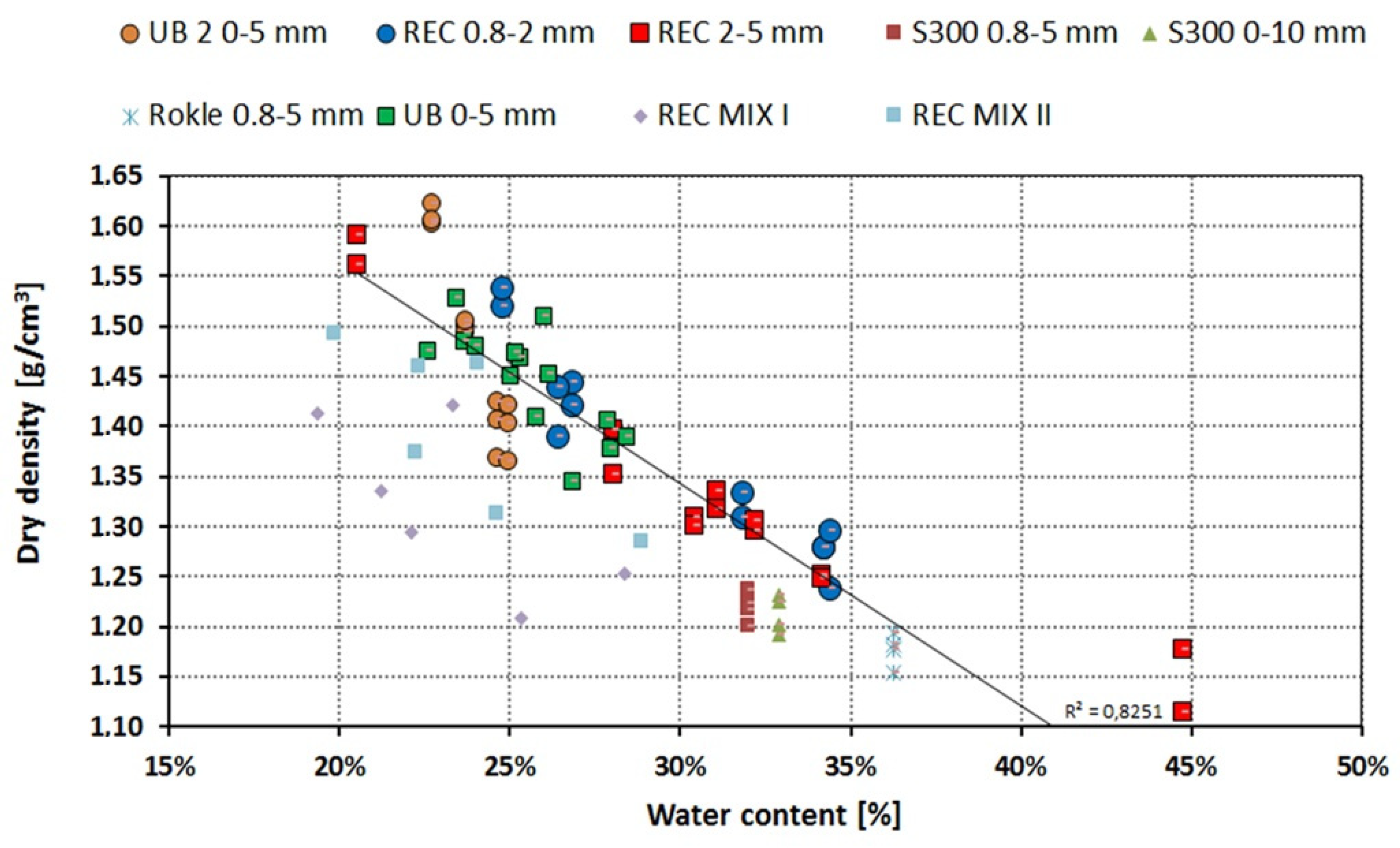
The compaction of the sprayed bentonite layer depends on the water content of the bentonite following spraying, as has been demonstrated by the results of previous tests conducted at the CTU, Prague, which are summarized graphically in Figure 7 and Figure 9. The dependency of dry density on the water content of the sprayed bentonite is marked by the line.
The results of the testing of the new materials (indicated as REC MIX I and REC MIX II in the graph in Figure 9 show the same level of compaction (dry density) as the “old” mixtures but with lower water contents, which is positive with respect to the sealing ability of the new bentonite materials.
The graph in Figure 2 shows the dependencies of the two most important properties: hydraulic conductivity and swelling pressure, on dry density. It is clear from the results shown graphically in Figure 9 that all the spraying tests fulfilled the requirements presented by the pond sealing layer project (hydraulic conductivity k < 10−11 m/s and swelling pressure σsw > 0.5 MPa).
Part of the research consisted of the optimization of the technology, with respect to which the main goals were the achievement of a sufficiently high dry density value and the limiting of the fallout of the sprayed material and the consequent occurrence of excessive dust while spraying. The amount of water used plays a key role in the spraying process (water flow to the nozzle of 75 L/h was found to be the optimal rate).
8. Conclusions
Research focusing on the development of sprayed bentonite has been underway at the Czech Technical University, Prague since 2007. Ongoing research is currently focused on sprayed bentonite applications for the sealing of fish-breeding ponds. After two years of testing, it seems that sprayed bentonite technology can be used for such a purpose. Recent results obtained based on spraying tests indicate that demanded geotechnical properties meet the requirements defined at the beginning of the project implementation (hydraulic conductivity k < 10−11 m·s−1 and swelling pressure σsw > 0.5 MPa). This method has both its advantages (low hydraulic conductivity, swelling ability) and disadvantages (the high rebound ratio during spraying). The next steps in the research will consist of the optimization of the technology and the spraying process. The development of the optimal bentonite mixture has now been concluded and resulted in the determination of the ideal grain size distribution and confirmation, in conjunction with the project’s industrial partners, that the materials can be produced at the industrial level. Now, the application of the developed material on the upstream slope of the real-scale model of a dam will be carried out and the effect of this measure on the limiting the seepage through the dam body will be measured and further assessed. Another part of further research will focus on the durability of the sealing layer created by the application of spraying including the investigation of possible ways to improve the durability and protect the sealing layer.
Author Contributions
J.S. and V.D. conceived and designed the physical model; J.S. performed the sprayed bentonite testing and the analysis of the test results; J.S. and V.D. jointly wrote the paper.
Acknowledgments
This article presents results obtained via the NAKI II DG16P02M036 “Conservation, repair and monitoring of historical pond dams as part of our cultural heritage” research project funded by the Ministry of Culture of the Czech Republic, with the support of SURAO (the Czech Radioactive Waste Repository Authority) and Czech Technical University grant funding. The support is greatly appreciated.
Conflicts of Interest
The authors declare no conflict of interest.
References
- Svoboda, J.; Vasicek, R. Preliminary geotechnical results from the Mock-Up-CZ experiment. Appl. Clay Sci. 2010, 47, 139–146. [Google Scholar] [CrossRef]
- Trpkošová, D.; Večerník, P.; Gondolli, J.; Havlová, V.; Hanusová, I.; Svoboda, J. Laboratory experiments on bentonite pellet saturation. In Radioactive Waste Confinement: Clays in Natural and Engineered Barriers; Geological Society: London, UK, 2016; Volume 443, pp. 73–83. [Google Scholar]
- Keramost, A.S. Products—Bentonites—Bentonites for Building Industry. Available online: http://www.keramost.cz/en/products/bentonites/bentonites-for-building-industry (accessed on 20 May 2018).
- Stastka, J.; Vasicek, R. The Development of Clay Barriers for Radioactive Waste Disposal at the Centre of Experimental Geotechnics. In Proceedings of the 21st International Conference nuclear Energy for New Europe, Ljubljana, Slovenia, 5–7 September 2012. [Google Scholar]
- Statska, J.; Pacovský, J.; Svoboda, J.; Hausmannová, L.; Vasicek, R. Výstavba, Provozování a Vyhodnocení Demonstračního Experimentu Mock-Up-Josef (Prodloužení 2016); XI. Project Report; ČVUT: Prague, Czech Republic, 2016. [Google Scholar]
- Vasicek, R. Research on the Thermophysical Behaviour of Engineered Barrier Material under Extreme Conditions. Ph.D. Thesis, CTU in Prague, Prague, Czech Republic, 2008. [Google Scholar]
- Svoboda, L. On aggregate blending. Beton TKS 2004, 4, 37–41. [Google Scholar]
- Teodori, S.P.; Weber, H.P.; Kohler, S.; Plotze, M.; Holl, M.; Muller, H.R. Granular bentonite production as buffer material for a Full-scale Emplacement (“FE”) experiment. In Proceedings of the 5th International ANDRA Meeting: Clays in Natural and Engineered Barriers for Radioactive Waste Confinement, Montpelier, France, 22–25 October 2012. [Google Scholar]
- Nakashima, H.; Saito, A.; Ishii, T. Method for producing high-density bentonite pellets using dry shrinkage. J. Nucl. Fuel Cycle Waste Technol. 2014, 21, 83–94. [Google Scholar] [CrossRef]
- Mahar, J.W.; Parker, H.W.; Wuellner, W.W. Shotcrete Practice in Underground Construction; UILU-ENG-75-2018 Final Report; FRA/ORD-75/90; University of Illinois and Federal Railroad Administration: Champaign, IL, USA, 1975; 516p. [Google Scholar]
- Pacovský, J.; Šťástka, J. Development of sprayed backfill technology. WIT Trans. Ecol. Environ. 2009, 122, 523–533. [Google Scholar]
- Concrete Spraying Machines Filamos. Available online: http://www.filamos.com/building-machinery/shotcreting-machines/ (accessed on 15 January 2018).
Figure 1.
The figure illustrates the physical model constructed at the Czech Technical University in Prague—Underground Research Centre Josef.
Figure 1.
The figure illustrates the physical model constructed at the Czech Technical University in Prague—Underground Research Centre Josef.

Figure 2.
Hydraulic conductivity and swelling pressure values for the selected B75 raw material [4].
Figure 2.
Hydraulic conductivity and swelling pressure values for the selected B75 raw material [4].

Figure 3.
(a) sketch of the compaction machine [9] used by the producer of the granulated bentonite (Keramost Plc.; Žatecká 1899/25; CZ 434 30; Most, The Czech Republic); (b) the B75 REC bentonite material (plates up to approx. 15 cm in length).
Figure 3.
(a) sketch of the compaction machine [9] used by the producer of the granulated bentonite (Keramost Plc.; Žatecká 1899/25; CZ 434 30; Most, The Czech Republic); (b) the B75 REC bentonite material (plates up to approx. 15 cm in length).

Figure 4.
Average grain size distributions for the tested granulated bentonite mixtures and comparison with the ideal grain size distribution given by the Fullers equation.
Figure 4.
Average grain size distributions for the tested granulated bentonite mixtures and comparison with the ideal grain size distribution given by the Fullers equation.

Figure 5.
(a) Photograph of the B75 REC MIX I material; (b) spray testing on the testing wall.

Figure 6.
(a) Scheme of the dry mix spraying machine [1] and (b) the SSB 14 DUO spraying machine produced by Filamos Ltd. (Hatě 546, CZ 261 01 Příbram III) [2].

Figure 7.
Graph showing the results of the evaluation of dry density depending on the water content of the sprayed Bentonite 75 (comparison of three mixtures tested in this project).
Figure 7.
Graph showing the results of the evaluation of dry density depending on the water content of the sprayed Bentonite 75 (comparison of three mixtures tested in this project).

Figure 8.
(a) Spraying of the bentonite between the concrete ribs during the construction of the first dam; (b) final sealing layer between the concrete ribs; (c) first dam following construction.
Figure 8.
(a) Spraying of the bentonite between the concrete ribs during the construction of the first dam; (b) final sealing layer between the concrete ribs; (c) first dam following construction.

Figure 9.
Results of the testing of the sprayed bentonite layer from this testing and comparison with data from previous research.
Figure 9.
Results of the testing of the sprayed bentonite layer from this testing and comparison with data from previous research.

Publisher’s Note: MDPI stays neutral with regard to jurisdictional claims in published maps and institutional affiliations. |
© 2018 by the authors. Licensee MDPI, Basel, Switzerland. This article is an open access article distributed under the terms and conditions of the Creative Commons Attribution (CC BY) license (https://creativecommons.org/licenses/by/4.0/).
Share and Cite
MDPI and ACS Style
Stastka, J.; David, V. The Testing of a Sprayed Bentonite Sealing Layer. Proceedings 2018, 2, 666. https://doi.org/10.3390/proceedings2110666
AMA Style
Stastka J, David V. The Testing of a Sprayed Bentonite Sealing Layer. Proceedings. 2018; 2(11):666. https://doi.org/10.3390/proceedings2110666
Chicago/Turabian StyleStastka, Jiri, and Vaclav David. 2018. "The Testing of a Sprayed Bentonite Sealing Layer" Proceedings 2, no. 11: 666. https://doi.org/10.3390/proceedings2110666