A Programmable 3-Channel Acoustic Wake-Up Interface Enabling Always-On Detection of Underwater Events within 20 µA †

Faculty of Electrical Engineering and Computing, University of Zagreb, Unska 3, 10000 Zagreb, Croatia
*
Author to whom correspondence should be addressed.
†
Presented at the Eurosensors 2018 Conference, Graz, Austria, 9–12 September 2018.
Proceedings 2018, 2(13), 768; https://doi.org/10.3390/proceedings2130768
Published: 23 November 2018
(This article belongs to the Proceedings of EUROSENSORS 2018)
Abstract
:We present an always-on acoustic wake-up sensor interface, designed for prolonging the autonomy of energy-hungry hardware for underwater acoustic surveillance. Proposed design enables the detection of a passing ship by simultaneous listening up to three arbitrarily defined frequency-bands within the 2.5 kHz range, and generates a wake-up signal upon finding a match with a digitally preset template describing signal’s discriminatory time-frequency features. In this paper, we propose the architecture of such fully programmable, multichannel, mixed-signal wake- up circuit. We show the implementation of a PCB prototype, characterize its sensitivity, analyze its current consumption, and verify its response on real-world hydrophone recordings. It is demonstrated that the design consumes only 6.4 µA per channel (in total <20 µA) with ultra-low- power COTS components, while listening.
1. Introduction
In a variety of underwater passive acoustic surveillance applications (security, marine-biology, environmental science etc.), bandwidth of signals of interest often spans up to 100 kHz. This requires continuous, high-fidelity signal acquisition, at sample rates as high as 100–200 kHz, real-time digital processing, and storage of terabytes of data. State-of-the-art underwater acoustic surveillance equipment typically requires 10–100 mW of power for such tasks [1,2], consequently suffering from either limited autonomy, or requiring bulky energy-storage units (batteries).
In order to miniaturize the passive acoustic surveillance equipment, prolong its autonomy, and lower the required data-storage capacity, an ultra-low-power always-on “wake-up” circuitry can be used [3] to trigger the signal acquisition and storage only in the presence of potential acoustic events of interest. In spite of significant research of always-on acoustic wake-up interfaces for terrestrial applications [4,5,6], limited work has been done in the context of detection of underwater acoustic events. Even then, most of the research efforts address asynchronous underwater communications by acoustic modems [2].
Here we demonstrate a design of an ultra-low-power acoustic wake-up interface for underwater detection of passing naval vessels (boats, ships) by analyzing the time-frequency signatures [7] of ship’s engine and propeller noise. Our key contributions w.r.t. the previous work [7] include the end- to-end design of a fully-programmable multichannel mixed-signal wake-up circuit, its implementation with state-of-the-art COTS components yielding minimal power consumption, characterization of circuit’s design parameters, and verification of its detection performance on hydrophone recordings of passing ships [8].
2. Materials and Methods
The design entails three analog-domain filtering channels decomposing the hydrophone’s signal (Vin) into arbitrary frequency bands (Figure 1a). Each channel consists of a digitally programmable active band pass filter. Each filter is designed in general impedance convertor (GIC) topology, and implemented using a pair of single-supply, CMOS, 100 kHz gain-bandwidth, 600 nA amplifiers (MCP6142, Figure 1b). Channel CH1 is designed to cover 200–500 Hz, CH2 for range between 500–1000 Hz, and CH3 1.0–2.5 kHz. Within these limits, each channel’s central frequency (fc), and pass-band bandwidth (B), are digitally programmable in 256 steps using I2C potentiometers Rfc, Rb (AD5144).
Intervals of signal presence within individual filtering channels (Vfilt) are localized in time first by extracting the envelopes (Venv) of filtered signals with active envelope trackers (MCP6141), and then performing single-bit quantization using comparators (TLV3701). Each channel’s comparator threshold voltage (Vcomp) is set by a digital potentiometer Rtr (AD5144).
Temporal relations between comparator responses (Vout) are finally analyzed by a 3-channel digital sequence recognition state-machine [7] (MSP430F2013), which wakes-up the DSP. Event’s template—an ordered sequence of discrete spectro-temporal states describing the vessel’s acoustic signature, is programmed into the MSP430F2013 by I2C as well. Consumption of MSP430F2013 is minimized by aggressive frequency scaling (11 kHz) and extensive use of low-power modes (LPM4, LPM3).
A PCB prototype implementation of the described wake-up circuit with proposed COTS components (Figure 2a) was used for experimental characterization of design parameters, testing of detection performance, and power consumption measurements.
3. Results
Results of characterization of the PCB prototype are summarized in Figure 2. First, adjustable ranges of each channel’s programmable parameters are shown in Figure 2b–d. Range of filtering channels’ central frequencies fc against digital potentiometers Rfc are verified in Figure 2b: CH1 200–500 Hz, CH2 500–1100 Hz, and CH3 1.0–2.6 kHz. RB’s are tuned for narrow, 150–200 Hz pass-bandwidths B at low and mid-frequency channels CH1 and CH2 (Figure 2c), and CH3 is enables extraction of broader bands of 500–800 Hz at the fc = 1.0 kHz, and 200–500 Hz at the maximal fc = 2.6 kHz. Rtr enables setting the comparator’s threshold voltage within approximately 50 mV (Figure 2d) around the envelope detector’s output voltage baseline (Venv), sitting on Vref = 0.9 V.
Ideally, gains of GIC filtering stages is 2 (Figure 2e). Frequency-dependent gain increase at the CH3 helps detection of high-frequency signal, typically exhibiting lower power-spectrum density (amplitude) than the signals at low frequencies (CH1, CH2). Sensitivity of the complete analog signal chain was measured at the envelope detector’s output, as a ripple-free headroom between the Venv and the signal’s baseline, floating around Vref (Figure 2f). Venv ripple affects the sensitivity at low frequencies at most. Sensitivity to input signals as low as Vin < 5 mV, enables direct coupling of the wake-up circuit to the sensor.
Event detection performance was tested on underwater recordings of 12 passes of an identical speedboat over an acoustic sensor submerged approx. 1 m under the surface in shallow water [8]. Signals were rescaled to yield max. Vin = {20…5} mV amplitude at pass-over. For each Vin, thresholds Rtr were trained on a single signal, and then tested on the remaining 11. A spectrogram of a training-pass is shown in Figure 3a. The associated circuit response, including a successful wake-up upon the simultaneous detection of uninterrupted 500 ms signal within all three arbitrarily set bands of interest (CH1 200–350 Hz, CH2 580–720 Hz, and CH3 1460–1920 Hz) is shown in Figure 3b. In the testing-phase, circuit was able to detect 8/11 speedboat passes with the Vin amplitude = 10 mV.
Current consumption was measured at 1.8 V. GIC filtering within 2.5 kHz implemented with MCP6142, costs 3.5 µA/channel. Each active envelope tracker contributes by 0.8 µA. Full-programmability, implemented with three digital potentiometers per channel (AD5144), adds 0.3 µA. Each comparator costs 1.8 µA, mostly due to the current flowing through the programmable resistor-divider network defining the Vcomp. Digital state machine implemented in MSP430F2013 consumes only 0.2 µA in listening [7]. This totals 6.4 µA/channel, or 19.4 µA for the three-channel prototype.
4. Discussion
Comparison with functionally and architecturally related state-of-the-art acoustic wake-up designs is given in Table 1. Consuming only 20 µA, the presented design (Figure 2a) achieves the best tradeoff between functionality (signal analysis capabilities), bandwidth and programmability, among COTS designs [3,4,5] (Table 1). An analogous ASIC design [6] shows potential for 100-fold power reduction.
5. Conclusions
We demonstrated a prototype of an always-on, multichannel, mixed-signal, fully-programmable wake-up sensor interface, consuming less than 20 µA, while listening for time-frequency signature of the acoustic event. Usage of the proposed circuit for on-demand triggering of the conventional underwater acoustic surveillance equipment [1,2], may reduce its average power consumption for more than two orders of magnitude. Apart from underwater security, diver safety, and marine biology, the circuit is applicable in many terrestrial event detection applications, including acoustic emission monitoring in industry and agriculture.
Acknowledgments
This research has been supported in part by the U.S. Office of Naval Research Global under the project ONRG-NICOP-N62909-17-1-2160, AWAKE—Ultra low power wake-up interfaces for autonomous robotic sensor networks in sea/subsea environments, and partially by Croatian Science Foundation under the project IP-2016-06-8379, SENSIRRIKA—Advanced sensor systems for precision irrigation in karst landscape.
Conflicts of Interest
The authors declare no conflict of interest. The founding sponsors had no role in the design of the study; in the collection, analyses, or interpretation of data; in the writing of the manuscript, and in the decision to publish the results.
References
- Caldas-Morgan, M.; Alvarez-Rosario, A.; Padovese, L.R. An Autonomous Underwater Recorder Based on a Single Board Computer. PLoS ONE 2015, 10, 1–18. [Google Scholar] [CrossRef] [PubMed]
- Develogic Subsea Systems: Acoustic Recorder and Signal Analyzer—Sono.Vault. Available online: http://www.develogic.de/products/ss-r/sonovault/ (accessed on 7 June 2018).
- Sanchez, A.; Blanc Clavero, S.; Yuste Pérez, P.; Piqueras Gozalbes, I.R.; Serrano Martín, J.J. Advanced Acoustic Wake-up System for Underwater Sensor Networks. In Communications in Information Science and Management Engineering; World Academic Publishing: Birmingham, UK, 2012; Volume 2, pp. 1–10. [Google Scholar]
- Mays, B.T. Design Report for Low Power Acoustic Detector ARL-TR-6552; Army Research Lab., Sensors and Electron Devices Directorate: Adelphi, MD, USA, 2013. [Google Scholar]
- Sutton, F.; Da Forno, R.; Gschwend, D.; Gsell, T.; Lim, R.; Beutel, J.; Thiele, L. The Design of a Responsive and Energy-efficient Event-Triggered Wireless Sensing System. In Proceedings of the International Conference on Embedded Wireless Systems and Networks (EWSN 2017), Uppsala, Sweden, 20–22 February 2017; pp. 144–155. [Google Scholar]
- Uldric, A.; John, C.; Alireza, D.; Theodore, W.B. Low Power, Long Life Design for Smart Intelligence, Surveillance, and Reconnaissance (ISR) Sensors. In Proceedings of the IEEE Conference on Technologies for Homeland Security (HST), Boston, MA, USA, 13–15 November 2012; pp. 631–636. [Google Scholar]
- Oletic, D.; Korman, L.; Magno, M.; Bilas, V. Time-Frequency Pattern Wake-up Detector for Low-power Always-on Sensing of Acoustic Events. In Proceedings of the 2018 IEEE International Instrumentation and Measurement Technology Conference (I2MTC 2018), Houston, TX, USA, 14–17 May 2018; pp. 1273–1278. [Google Scholar]
- Underwater Video of Twin Engine Boat Props High Speed. Available online: https://www.youtube.com/watch?v=6uQ7IDqbmAE (accessed on 7 June 2018).
Figure 1.
The 3-channel always-on wake-up interface. (a) Architecture; (b) Design of an individual analog channel (GIC filter, active envelope tracker, comparator).
Figure 1.
The 3-channel always-on wake-up interface. (a) Architecture; (b) Design of an individual analog channel (GIC filter, active envelope tracker, comparator).
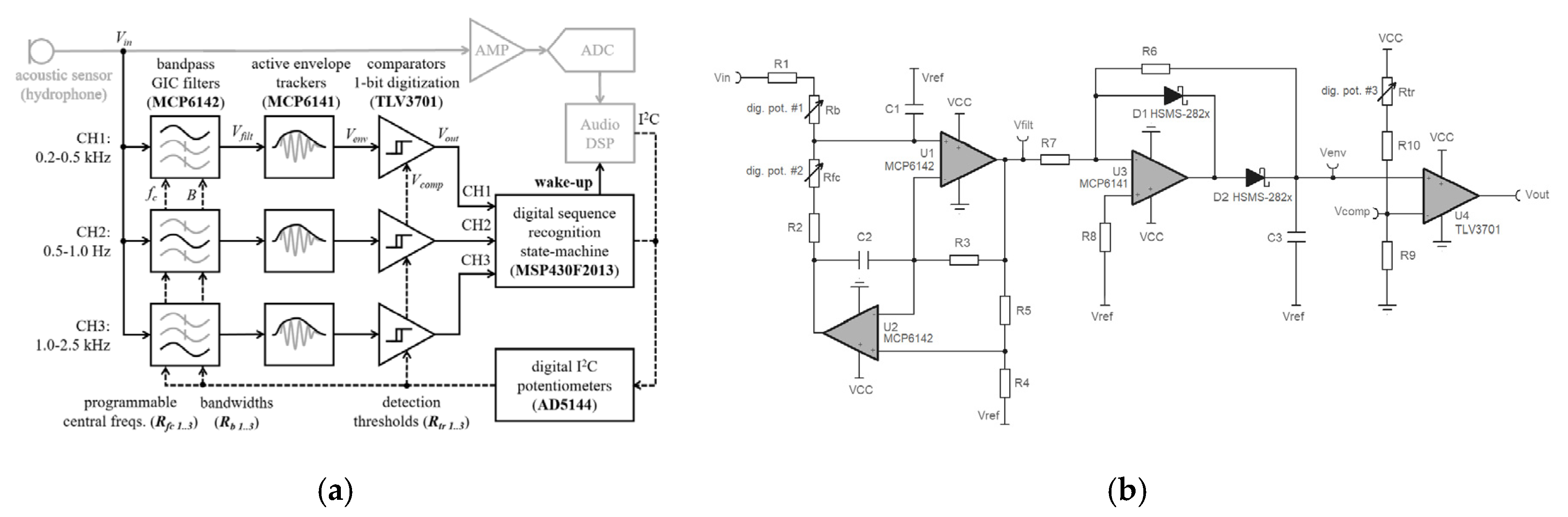
Figure 2.
Design characterization. (a) PCB; (b) Range of filters central frequencies (adjusted by Rfc), (c) bandwidths (set by Rb), and (d) span of comparators thresholds (Rtr); (e) Filters’ gains (Vfilt/Vin); (f) Envelope trackers’ sensitivities (Venv).
Figure 2.
Design characterization. (a) PCB; (b) Range of filters central frequencies (adjusted by Rfc), (c) bandwidths (set by Rb), and (d) span of comparators thresholds (Rtr); (e) Filters’ gains (Vfilt/Vin); (f) Envelope trackers’ sensitivities (Venv).

Figure 3.
An acoustic event detection with the always-on wake-up circuit. (a) A typical underwater spectrogram signature of a passing speedboat [8]; (b) The associated wake-up circuit response (Vin = 20 mV). DSP processing may be initiated on the rising edge of the wake-up signal.
Figure 3.
An acoustic event detection with the always-on wake-up circuit. (a) A typical underwater spectrogram signature of a passing speedboat [8]; (b) The associated wake-up circuit response (Vin = 20 mV). DSP processing may be initiated on the rising edge of the wake-up signal.


Table 1.
Current consumption breakdown (VCC = 1.8 V), and comparison to the related acoustic wake-up designs. (Legend: - feature not present; feature present, but consumption not reported).
Table 1.
Current consumption breakdown (VCC = 1.8 V), and comparison to the related acoustic wake-up designs. (Legend: - feature not present; feature present, but consumption not reported).
| Ref. | Techn. | Functionality | Band-Width | Filter/ch. | Envelope Tracking/ch. | 1-bit Digitizer/ch. | Program Mability/ch. | Classifi-Cation | Single Channel | Total (all ch.) |
|---|---|---|---|---|---|---|---|---|---|---|
| [3] | COTS | Fixed, single ch. Acoustic modem with address decoding | 150 kHz | - | - | 4.5 µA | - | |||
| this | COTS | dig. programmable 3 ch. filtering, 1-bit envelope digit., time-freq. template matching | 2.5 kHz | 3.5 µA | 0.8 µA | 1.8 µA | 0.3 µA | 0.2 µA | 6.4 µA | 19.4 µA |
| [4] | COTS | fixed, single-ch., 1-bit digit., periodicity detection in FPGA | 380 Hz | 4.2 µA | - | 1.1 µA | - | 20 µA | - | 85 µA |
| [5] | COTS | Fixed, single ch., detection by amplitude thresholding | 20 kHz | - | - | 3.2 µA | - | - | 3.2 µA | - |
| [6] | ASIC | multi-ch. filtering, env. Peak detect vs amb. noise | 100 Hz | 0.34 nA | - | - | 4.3 nA | - |
Publisher’s Note: MDPI stays neutral with regard to jurisdictional claims in published maps and institutional affiliations. |
© 2018 by the authors. Licensee MDPI, Basel, Switzerland. This article is an open access article distributed under the terms and conditions of the Creative Commons Attribution (CC BY) license (https://creativecommons.org/licenses/by/4.0/).
Share and Cite
MDPI and ACS Style
Oletic, D.; Gazivoda, M.; Bilas, V. A Programmable 3-Channel Acoustic Wake-Up Interface Enabling Always-On Detection of Underwater Events within 20 µA. Proceedings 2018, 2, 768. https://doi.org/10.3390/proceedings2130768
AMA Style
Oletic D, Gazivoda M, Bilas V. A Programmable 3-Channel Acoustic Wake-Up Interface Enabling Always-On Detection of Underwater Events within 20 µA. Proceedings. 2018; 2(13):768. https://doi.org/10.3390/proceedings2130768
Chicago/Turabian StyleOletic, Dinko, Marko Gazivoda, and Vedran Bilas. 2018. "A Programmable 3-Channel Acoustic Wake-Up Interface Enabling Always-On Detection of Underwater Events within 20 µA" Proceedings 2, no. 13: 768. https://doi.org/10.3390/proceedings2130768