Proceeding Paper

Transverse Distribution of Concentrated Loads on Timber Composite Floors †

ISISE, Civil Engineering Department, University of Coimbra, Rua Luís Reis Santos—Pólo II, 3030-788 Coimbra, Portugal
*
Author to whom correspondence should be addressed.
Presented at the 2nd International Research Conference on Sustainable Energy, Engineering, Materials and Environment (IRCSEEME), Mieres, Spain, 25–27 July 2018.
Proceedings 2018, 2(23), 1421; https://doi.org/10.3390/proceedings2231421
Published: 1 November 2018

Abstract

:
Timber-concrete composite floors can be seen as bi-dimensional elements constituted by repeatable longitudinal elements (timber beams) connected through an element capable to spread the load on the transverse direction (concrete slab). This is usually a fact to “take advantage of” in terms of design, in the light of current regulations, with the analysis of a “T-shape” beam. Nevertheless, when concerning the action of concentrated loads, considering them supported entirely by the beam to which they are applied can result in a disadvantage rather than an advantage. This study focus on the distribution of load in the transverse direction when composite floors are subjected to concentrated loads. There were analyzed not only timber-concrete composite floors, that already have proven their value, but also relatively new solutions as those using cross laminated timber (CLT) combined with steel beams. The results show that the load received by “the loaded beam” can be far from 100%.

1. Introduction

Timber-concrete composite structures arose at the early decades of the last century [1,2,3] as a consequence of the steel shortage in the period between World Wars. As well as the reinforced concrete structures, these composite structures have been developed in order to take the best advantage of each material that compose them. Besides performing well when subjected to tension efforts, the timber element is, at the same time, light and obtained from a renewable resource. The good mechanical behavior of concrete when subjected to compression is well known and, when compared with a solution made solely by timber, it adds stiffness, improves load bearing capacity, sound insulation and vibration performance of these composite solutions.
In the last decades, numerous developments took place in the field of timber and engineered timber products. At the end of the 20th century, beginning of the 21st century a large-sized engineered timber product consisting of perpendicular layers, made by juxtaposed boards, started to gain market [4]. This product, known as cross-laminated timber (CLT) or “X-lam”, is quite versatile and can be applied in several applications, either in- and out-of-plane. CLT is also used to build composite structures, e.g. composite floors, combined with a concrete upper layer or with steel beams.
The present study focuses on timber-concrete and CLT-steel composite floors, specifically on their behavior when subjected to concentrated loading. A common approach to the design of timber-concrete bi-dimensional elements, as being constituted by repeatable longitudinal elements connected through an element capable to spread the load on the transverse direction, consists of considering a “T-shape” beam to which the entire load is associated [5]. This do not correspond to what is the actual behavior of these composite floors. In fact, the amount of load transmitted to the remaining longitudinal elements can overcome 60% [6]. If this could be considered in the design of these composite floors, it would give the designer a wide margin to turn it less expensive and environmentally friendly.

2. Goals and Approach

As exposed, the current standardization does not take advantage of the fact that the beam over which the load is applied does not receive it entirely. This study aims to understand how the concentrated load is distributed transversally through the composite floor in order to obtain a final composite solution more economical and ecological.
Two main composite floors were studied. They differ essentially on the materials that compose them:
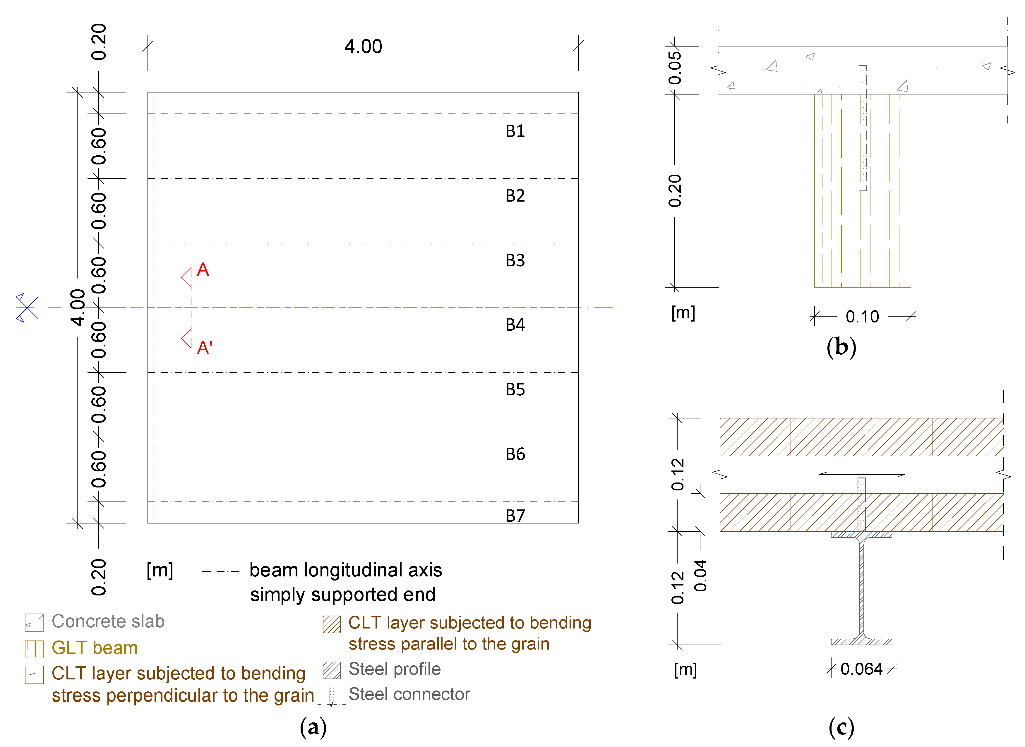
  • Timber-concrete composite (TCC) floors, composed by a concrete thin slab mechanically connected to various timber beams; and
  • CLT-Steel (CLT-S) floors, composed by a CLT slab mechanically connected to various steel beams.
To perform this analysis a finite element (FE) based model, developed and validated by the authors [7], was used. The numerical model was developed on SAP2000 using frame elements to model the beams, shell elements to model the slabs and decks and link elements to model the connectors. The composite floors were subjected to concentrated point and line loads applied at the slab level, right above each beam, at mid and quarter span and aligned with the beam longitudinal axis, respectively.
Although it is expected soon, neither the CLT nor the timber-concrete or timber-steel composite elements have a standardized design procedure. Therefore, from the common approaches to the design of these composite floors the one explained in the Annex B of EN 1995 [5] was the chosen one. For the same structural scheme (4.00 × 4.00 m2, with beams 0.60 m apart from each other), both floors were designed aiming at obtaining similar effective stiffnesses. The components of each of the modeled composite floors, geometrical properties and material characteristics are presented in Figure 1 and Table 1.

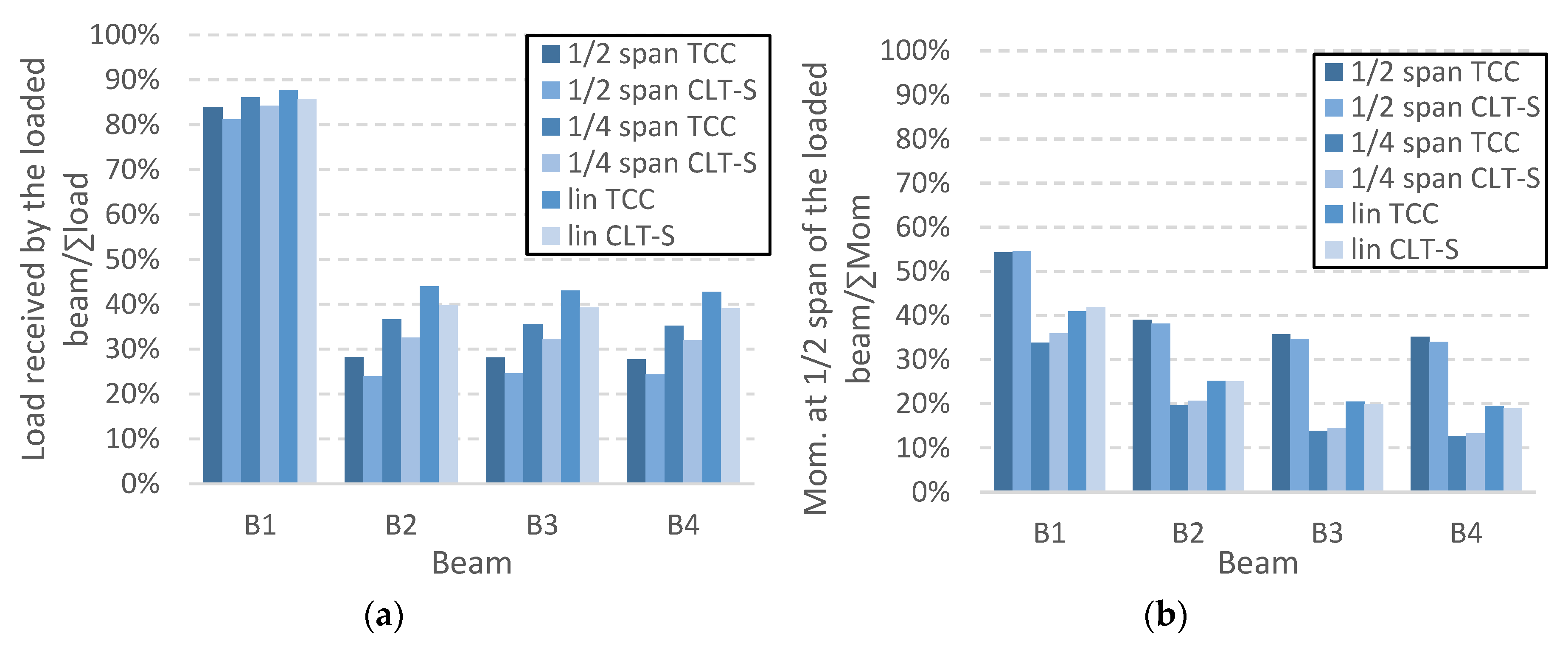
3. Results and Discussion

To analyze the manner in which the loading is transversally distributed to each beam, quantities as the support reactions (sr), the vertical displacement (vd) and longitudinal bending moment (bm) at mid span were collected and analyzed. Due to the symmetrical properties of the modeled floors relatively to the central beam (B4), only the results from the first four beams are presented. Figure 2 summarizes the results in terms of sr and bm distribution, for the three loading cases. The existence of load distribution is absolutely clear, being more evident as the loaded beam is the innermost. In terms of sr the distribution percentages were of about 12% (lin) to 19% (½ span) for the external beams (B1 and B7) and about of 57% (lin) to 76% (½ span) for the central beam (B4). As for the bm, there is a higher distribution concerning the external beams, when compared with that of sr, varying between 45% (½ span) and 66% (¼ span); for the central beam the percentages are, once again, more expressive 65% (½ span) to 87% (¼ span). There is a small difference (max. of 4%) when comparing the results obtained for the two floors. This could be justified by the fact that, although the floors had similar effective stiffnesses, the concrete slab and CLT deck have not, with the stiffer element having greater ability to spread the load.

4. Conclusions

Concentrated loads are common loadings on building floors. The use of composite floors with wood-engineered products, as GL and CLT, whether better known solutions, as the timber-concrete floors, or new ones, as the CLT-steel floors, showed to have the ability to distribute the load that is applied immediately above the beam under consideration to the adjacent ones. The values of distribution were quite significant in some cases, reaching about 75% for the central beam loaded at mid span.

Author Contributions

A.D. and S.M. conceived the studied issue; S.M. developed the numerical model, performed the modelling tasks, analyzed the data and wrote the paper; A.D. and S.L. wrote the paper.

Funding

This work was partly financed by FEDER funds through the Competitiveness Factors Operational Programme—COMPETE and by national funds through FCT—Foundation for Science and Technology within the scope of the Project POCI-01-0145-FEDER-007633 e POCI-01-0247-FEDER-017867.

Conflicts of Interest

The authors declare no conflict of interest. The founding sponsors had no role in the studied issue; in the collection, analyses, or interpretation of data; in the writing of the manuscript, and in the decision to publish the results.

References

  1. Emperger, F. Der Holzbeton. Dinglers Polytech. J. 1920, 335, 109–112. [Google Scholar]
  2. Mueller, P. Decke aus hochkantig stehenden Holzbohlen oder Holzbrettern und Betondeckschicht, A.a.d.P. Patentschau aus dem Betonbau und den damit verwandten Gebieten. DE334431C, 14 March 1921. [Google Scholar]
  3. Seiler, J.F. Composite Wood and Concrete Construction. U.S. Patent 2,022,693, 3 December 1935. [Google Scholar]
  4. Brandner, R.; Flatscher, G.; Ringhofer, A.; Schickhofer, G.; Thiel, A. Cross laminated timber (CLT): Overview and development. Eur. J. Wood Wood Prod. 2016, 74, 331–351. [Google Scholar] [CrossRef]
  5. EN1995. Eurocode 5: Design of timber structures. In Part 1-1: General—Common Rules and Rules for Buildings; CEN, Ed.; CEN: Brussels, Belgium, 2004. [Google Scholar]
  6. Monteiro, S.R.S.; Dias, A.M.P.G.; Lopes, S.M.R. Transverse distribution of internal forces in timber–concrete floors under external point and line loads. Construct. Build. Mater. 2016, 102, 1049–1059. [Google Scholar] [CrossRef]
  7. Monteiro, S.R.S.; Dias, A.M.P.G.; Lopes, S.M.R. Bi-dimensional numerical modeling of timber–concrete slab-type structures. Mater. Struct. 2015, 48, 3391–3406. [Google Scholar] [CrossRef]
  8. FprEN14080. Timber structures—Glued laminated timber and glued solid timber—Requirements. In Strength Classes; CEN, Ed.; CEN: Brussels, Belgium, 2013. [Google Scholar]
  9. EN338. Structural timber. In Strength Classes; CEN, Ed.; CEN: Brussels, Belgium, 2003. [Google Scholar]
  10. EN1992. Eurocode 2: Design of concrete structures. In Part 1-1: General Rules and Rules for Buildings; Part 2: Concrete Bridges; Design and Detailing Rules; CEN, Ed.; CEN: Brussels, Belgium, 2004. [Google Scholar]
  11. EN1993. Eurocode 3: Design of steel structures. In Part 1-1: General Structural Rules; CEN, Ed.; CEN: Brussels, Belgium, 2005. [Google Scholar]
Figure 1. Composite floor geometry and components: (a) plan view scheme; cross section A-A’: (b) TCC floor; (c) CLT-S floor.
Proceedings 02 01421 g001
Figure 2. Transverse distribution of: (a) sr and (b) bm.
Proceedings 02 01421 g002
Table 1. Material and cross-sectional characteristics.
Composite FloorTimber GradeConcreteSteel
TCC0.10 × 0.20 m2 GL 24 h (timber layers made of laminations of graded as T14 1 (C24 2))0.05 m thick C25/30 3 concrete-
CLT-S3 layer (2 along the x-direction), 40 mm thick, CL 24 (timber layers made of laminations of graded as T14 1 (C24 2))-IPE120 S275 4 profile
1 According to FprEN 14080 [8]. 2 According to EN 338 [9]. 3 According to EC2 [10]. 4 According to EC3 [11].
Publisher’s Note: MDPI stays neutral with regard to jurisdictional claims in published maps and institutional affiliations.

