Experimental Investigation on the Acoustic Scattering Matrix for a Centrifugal Pump †


1
Department of Energy, University of Oviedo, Campus de Viesques s/n, 33271 Gijón, Asturias, Spain
2
National Research Center of Pumps, Jiangsu University, Xuefu Road No. 301, Zhenjiang 212013, Jiangsu, China
*
Author to whom correspondence should be addressed.
†
Presented at the 2nd International Research Conference on Sustainable Energy, Engineering, Materials and Environment (IRCSEEME), Mieres, Spain, 25–27 July 2018.
Proceedings 2018, 2(23), 1489; https://doi.org/10.3390/proceedings2231489
Published: 1 November 2018
(This article belongs to the Proceedings of The 2nd International Research Conference on Sustainable Energy, Engineering, Materials and Environment)
Abstract
:Fluid-dynamic noise in centrifugal pumps as a significant sound source in piping systems has gained high attention due to the requirements of vibration and noise reduction in many fields. The acoustic characteristics of the fluid-dynamic noise from pumps are bound to be affected by the pipe ports and other piping components during the operation of the pump system. Therefore, the direct measurement of pressure pulsations in the pipeline of a test pump does not directly reflect the acoustic properties of the pump itself, because the coupling effects of the hydraulic system, which can even cause standing waves, may be seriously misleading in some situations. In this paper, an alternative experimental method has been applied to identify the so-called acoustic scattering matrix of a laboratory centrifugal pump. The elements of the scattering matrix characterize how the acoustic pressure waves are transmitted or reflected from the pump ports, i.e., it summarizes the passive acoustic properties of the pumps. For the tests, the test pump was connected in parallel to another auxiliary pump driven with a variable-frequency that played the role of an external sound source. The acoustic pressure waves induced in the suction and discharge pipes were mathematically decomposed into the corresponding incoming and exiting pressure waves travelling in the positive (P+) and negative (P−) directions respectively, by means of the two-microphone procedure. This paper shows the elements of the scattering matrix determined for the test pump as a function of frequency. These results represent a reference for subsequent theoretical research on the acoustic scattering matrix of centrifugal pumps.
Published: 1 November 2018
1. Introduction
Centrifugal pumps, which are widely used to transfer liquids in a large variety of fields, are usually simple machines consisting in a bladed rotor (impeller) inside a static volute casing with inlet and outlet ports. However, the internal flow pattern is very complex since it is fully three-dimensional unsteady and turbulent flow, with regions of flow separation, recirculation and swirl [1]. While this precludes the analytical determination of fluid-dynamic variables of centrifugal pumps, the prediction of the internal fluid-dynamic noise is even more difficult and the estimations are little reliable. Therefore, investigation of the acoustic properties of centrifugal pumps requires the support of experimental data. Besides, the excitation of fluid-dynamic noise inside pumps represents a primary sound source for the hydraulic system formed by the external piping [2]. However, the pressure pulsations measured at a single position in the pipeline do not directly reflect the acoustic behavior of the pump itself, due to the coupling effects of the hydraulic circuit.
The scattering matrix model is usually adopted to evaluate the acoustic passive properties of pumps [3,4], i.e., which describe how the incoming pressure waves on each port are transmitted or reflected. This paper proposes a procedure to evaluate the elements of the scattering matrix of a test pump in the laboratory of the Department of Energy at the University of Oviedo while avoiding the effects of pump-circuit coupling. Following fundamentals of acoustic theory [4] and previous research results [5,6], the procedure is based on the acquisition of several pressures signals under different excitation conditions. Results are presented as a function of frequency.
2. Hydraulic System
The test pump is a conventional centrifugal pump with a specific speed of 0.46. In order to identify the elements of its scattering matrix, first the acoustic pressure waves entering and exiting the two ports of the pump had to be obtained under different external acoustic loads. This required decomposing the acoustic pressure signals recorded at two or more locations along both the suction and discharge pipes. Figure 1 shows a schematic of the hydraulic set-up and the instrumentation. In this system, the test pump was installed in parallel with an auxiliary pump that acted as an external loudspeaker, because it was operated with a very low flow-rate and so it produced relatively high pressure pulsations at its blade-passage frequency. The magnitude and frequency of the pressure fluctuations induced at the measurement positions close to the test pump could be modified by maneuvering the valves of the system and by varying the rotation speed of the auxiliary pump. During each test, a multi-channel device (IMC Cronos-PL2) recorded the pressure fluctuation signals from several high sensitivity piezoelectric sensors (Kistler 701A), each connected to a charge amplifier. Then the pressure signals were post-processed as follows.
3. Methodology
For this analysis, the acoustic pressure waves along the piping are assumed to be plane waves, because the pipe diameter of the pump system is at least 40 times lower than the sound wave length λ for the frequency range considered (up to 280 Hz). Figure 2 presents a scheme of a pipe section with two pressure sensors and plane pressure waves travelling in opposite directions. At the left side of the pipe an ideal sound source is radiating plane pressure waves while the right side of the pipe has an equivalent acoustic impedance ZR. The pressure sensors at positions X2 and X1, separated by a distance S, measure the pressure fluctuations P1(x,t) and P2(x,t) respectively. The amplitudes and phases of each plane pressure wave must satisfy the following relationships for each frequency:
where j is the imaginary unit, k is wave number and ω = 2πf is an angular frequency. The pressure waves traveling in opposite directions so obtained result from the acoustic interaction between the sound source (the auxiliary pump) and the pipe system, and so they are different when modifying the valve configuration of the connecting piping between both pumps even if the sound source remains unchanged.
Figure 3 presents a scheme of the test pump considered as a linear two-port acoustic element with two state variables at each port: the entering and exiting pressure waves ( and ) at the suction and discharge pipes. The relation between those state variables when the sound source is external (as in the present case) is given by the so-called scattering matrix S, defined as:
where the subscripts i and o indicate the plane waves travelling along the inlet and outlet pipes of the pump, and represent the inlet and outlet reflection coefficients, and and are the inlet and outlet transmission coefficients, respectively.
To determine the scattering matrix of the test pump, two pairs of pressure sensors separated by distances L1 and L2 were installed at the suction and discharge pipes of test pump respectively. The signals obtained at different frequencies and for different circuit configurations were processed by using Equations (1)~(3) resulting in a large set of experimental data on travelling pressure waves under different acoustic loads. However, the elements of the scattering matrix are expected to remain constant for a given frequency, i.e., each single set of experimental data should verify Equation (4). Therefore, the systematic application of Equation (4) to all the N data groups results in two large systems of N equations, each with just two unknowns: the two elements of either the first or the second line of S. These two overdetermined systems of N equations can be solved by means of a least square errror procedure, so that the errors and as defined by Equations (5) and (6) become minima:
4. Pump Scattering Matrix
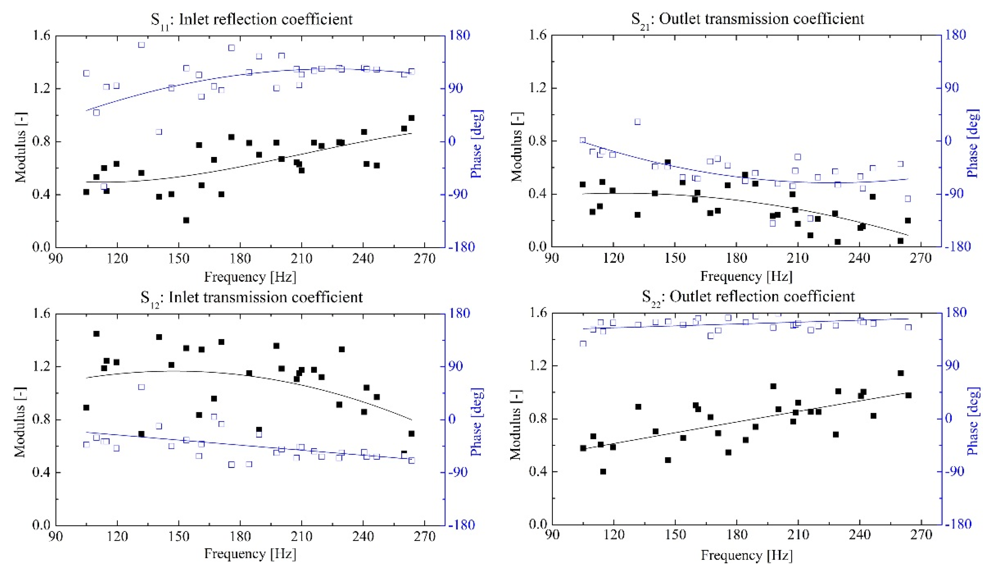
Figure 4 presents the results so obtained for the modulus and arguments of the four elements of the scattering matrix of the test pump as a function of frequency. Though the data present some dispersion, trending lines can be easily appreciated for all cases. Based on energy conservation considerations, the modulus of S11 and S22 should not be higher than 1, and this is what happens at all frequencies. In particular, S22 takes values close to 1, which means that most of the on-coming sound to the discharge port becomes reflected back. Besides, S21 is always lower than unity but S12 becomes higher. The latter is just due to the lower cross section of the discharge pipe relative to the suction side, and so the energy conservation is still verified, as expected. In general, the results obtained compare very well to those measured by Bardeleben et al. [6], data dispersion included, who tested a pump with a specific speed of 0.312. The most significant difference corresponds to the reflection coefficient S11, but this discrepancy can be explained by the different specific speed between both pumps (50% higher for the present pump) and the corresponding difference in suction geometry.
5. Conclusions
An experimental method has been applied to determine the acoustic scattering matrix of a centrifugal pump, which characterizes the passive acoustic properties by means of the reflection and transmission coefficients at the two pump ports. The results obtained for a range of frequencies verify the energy conservation law and compare well with data of the literature. Despite the data present some dispersion, they can be considered adequate to contrast the theoretical predictions from acoustic models, as intended by the authors for subsequent study.
Author Contributions
G.L. conducted the tests, analyzed the data and wrote the paper; J.P. conceived the study and designed the experiments; Y.W. provided guidance during the investigation.
Acknowledgments
Guidong Li gratefully acknowledges the grant provided by the “China Scholarship Council”.
Conflicts of Interest
The authors declare no conflict of interest.
References
- Choi, J.S.; McLaughlin, D.K.; Thompson, D.E. Experiments on the unsteady flow field and noise generation in a centrifugal pump impeller. J. Sound Vib. 2003, 263, 493–514. [Google Scholar] [CrossRef]
- Chu, S; Dong, R; Katz, J. Relationship between unsteady flow, pressure fluctuations, and noise in a centrifugal pump—Part A: Use of PDV data to compute the pressure field. J Fluid Eng. 1995, 117, 24–29. [Google Scholar] [CrossRef]
- Yamamoto, K.; Müller, A.; Ashida, T.; Yonezawa, T.; Avellan, F.; Tsujimoto, Y. Experimental method for the evaluation of the dynamic transfer matrix using pressure transducers. J. Hydraul. Res. 2015, 53, 466–477. [Google Scholar] [CrossRef]
- Munjal, M.L. Acoustics of Ducts and Mufflers; John Wiley & Sons: Chichester, UK, 2014. [Google Scholar]
- Parrondo, J.; Pérez, J.; Barrio, R.; Gonzalez, J. A simple acoustic model to characterize the internal low frequency sound field in centrifugal pumps. Appl. Acoust. 2011, 72, 59–64. [Google Scholar] [CrossRef]
- Bardeleben, M.J.R.; Weaver, D.S. Estimation of the acoustic scattering matrix for a centrifugal pump. In Proceedings of the ASME 2002 International Mechanical Engineering Congress and Exposition, New Orleans, LA, USA, 17–22 November 2002. [Google Scholar]
Figure 1.
Schematic view of the experimental facility.

Figure 2.
Schematic view of the acoustic pipeline.
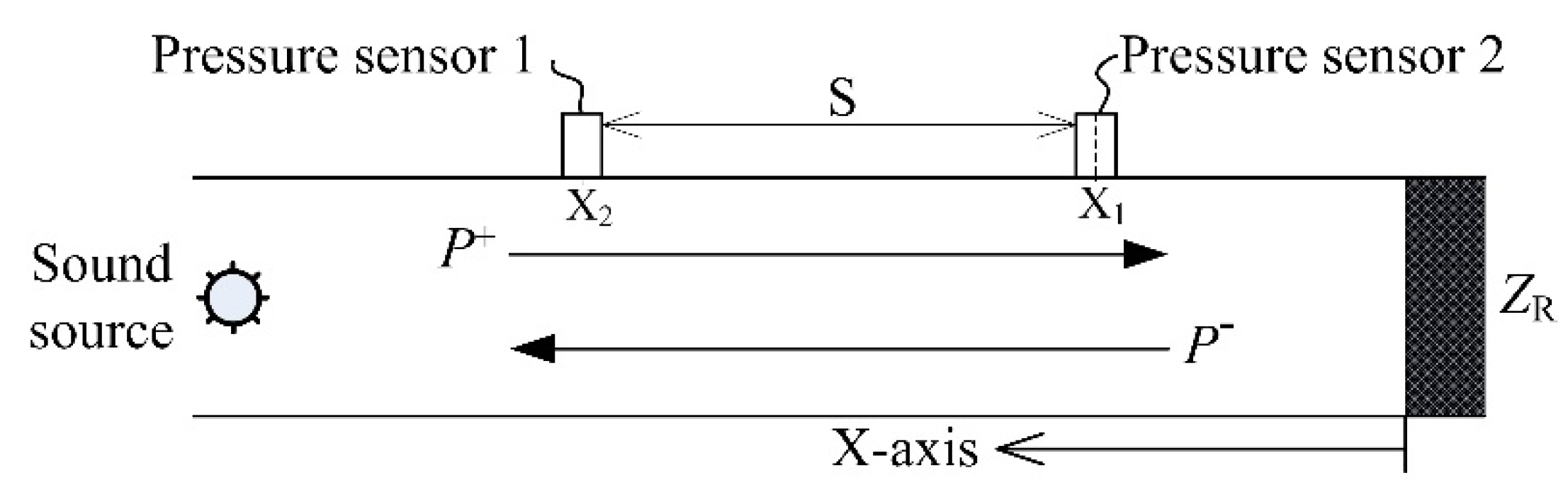
Figure 3.
Acoustic system of the composition of the pump and pipeline.

Figure 4.
Measured data for pump scattering matrix.
Publisher’s Note: MDPI stays neutral with regard to jurisdictional claims in published maps and institutional affiliations. |
© 2018 by the authors. Licensee MDPI, Basel, Switzerland. This article is an open access article distributed under the terms and conditions of the Creative Commons Attribution (CC BY) license (https://creativecommons.org/licenses/by/4.0/).
Share and Cite
MDPI and ACS Style
Li, G.; Parrondo, J.; Wang, Y. Experimental Investigation on the Acoustic Scattering Matrix for a Centrifugal Pump. Proceedings 2018, 2, 1489. https://doi.org/10.3390/proceedings2231489
AMA Style
Li G, Parrondo J, Wang Y. Experimental Investigation on the Acoustic Scattering Matrix for a Centrifugal Pump. Proceedings. 2018; 2(23):1489. https://doi.org/10.3390/proceedings2231489
Chicago/Turabian StyleLi, Guidong, Jorge Parrondo, and Yang Wang. 2018. "Experimental Investigation on the Acoustic Scattering Matrix for a Centrifugal Pump" Proceedings 2, no. 23: 1489. https://doi.org/10.3390/proceedings2231489