Rice Starch-Templated Synthesis of Nanostructured Silica and Hematite †


Centre of Foundation Studies, Universiti Teknologi MARA (UiTM), Cawangan Selangor, Kampus Dengkil, Dengkil 43800, Selangor, Malaysia
†
Presented at the 1st International Online Conference on Nanomaterials, 1–15 September 2018; Available online: https://iocn-2018-1.sciforum.net/.
Proceedings 2019, 3(1), 1; https://doi.org/10.3390/IOCN_2018-1-05491
Published: 30 August 2018
(This article belongs to the Proceedings of IOCN 2018)
Abstract
:Synthesis of nanostructured materials is not straightforward, which involves the complicated use of surfactant templates. Currently, only non-renewable resources that are hazardous and toxic are used to produce the surfactant templates in the industries. This study presents an environmentally friendly and efficient route for the synthesis of the nanostructure of both silica and hematite using rice starch as a promising biomaterials template. The rice starch-templated synthesis yield both hematite and silica with nano-size and high surface area. In particular, the nanostructured silica showed a pseudo-spherical morphology with a nano-size from 13 to 22 nm, amorphous structure and surface area of 538.74 m2/g. On the other hand, the nanostructured hematite showed a spherical-shaped morphology with a nano-size from 24 to 48 nm, and surface area of 20.04 m2/g. More importantly, the use of rice starch-template for a greener approach in the synthesis of nanomaterials was successfully outlined.
1. Introduction
Nanostructured materials are one of the very special structures that have led to the enhancement of properties that are not available for any other materials. A variety of synthesis methods such as sol-gel process [1], sonochemical route [2], surface polymerization processes [3], colloidal templating methods and template assisted approaches have been used for the fabrication of materials with nanostructured properties [4]. Among the various synthesis methods, template-assisted approaches are considered very efficient, most effective and frequently selected methods for the preparation of nanostructured materials. To date, various templating agents have been introduced for template-assisted methods in the form of additives and/or surfactants such as polymethylmethacrylate (PMMA) [5], polystyrene (PS) latex [6], and n-propyl amine [7]. Notably, only non-renewable resources that are hazardous and toxic are used to produce the additive or surfactant templates in the industries.
For environmentally-friendly approaches, starch has been successfully employed as green templates for the synthesis of nanostructured materials [8,9]. In this way, the use of additives and/or surfactants template could be avoided, and benign reagents from biomaterials can be introduced. In the case of starch, it is composed of linear amylose and branched amylopectin structures, that have hydroxyl (OH) and aldehyde (COH) as the functional groups. Previously, the OH and COH groups were recognized in facilitating adsorption of the desired precursors onto their reactive surfaces, for the synthesis of different nanostructured materials [9,10]. Despite this interest, no one, to the best of author’s knowledge, has utilized starch for the synthesis of different metals, particularly metalloids and transition metals of silica and hematite. Herein, an environmentally friendly and efficient route for the synthesis of nanostructured of both silica and hematite using rice starch as a promising biomaterials template are presented.
2. Results and Discussion
The aim of this study was to prepare nanostructured metals of both silica (metalloids) and hematite (transition metals). This is the first step towards enhancing the understanding for the synthesis of the different type of metals. To illustrate, two synthesis methods represent by Route 1 and 2 that consisted of two synthetic preparations were designed, as shown in Figure 1. For Route 1, the starting precursor of rice starch and hydrolyzed starch are denoted as rice starch (RS) and hydrolysis of rice starch (HRS), respectively (Scheme 1). Subsequently, aqueous ethanol (EtOH) and tetraethyl orthosilicate (TEOS) were added to the HRS for complete polycondensation of TEOS into a sol-gel paste, which is referred to as SG-HRS before calcined to produce nanostructured silica (SiNS) powder (Scheme 2).
As can be seen in Figure 1, the hematite was synthesized according to Route 2. In Scheme A, an appropriate amount of FeSO4·7H2O, HCl and RS were added to double distilled water heated to 70 °C. Then, the mixtures were left to room temperature before being filtered, washed with double distilled water and dried in oven at 100 °C for overnight to produce a dark paste denoted as RS-HNP, followed by calcination to 700 °C (heating rate of 5 °C/min), before slowly cooled to room temperature (Scheme B). The collected reddish-brown powder of nanostructured hematite is referred to as HNS.
2.1. Morphology Study
Figure 2 shows the Field Emission Scanning Electron Microscopy (FESEM) micrograph for the synthesized metals of SiNS and HNS. In Figure 2a, the FESEM micrograph image shows loose aggregation of pseudo-spherical morphology for SiNS. Based on the FESEM image, SiNS were measured in the range of 13 to 22 nm diameters. It is worth mentioning that partial macrophase separation during the sol-gel aging process and subsequent sintering effect during calcination at high temperature had affected the SiNS uniformity. In contrast, the HNS revealed almost monodispersed spherical-shaped nanoparticles as shown in Figure 2b. Judging from the FESEM image, HNS were spherical nanoparticles with a size range of 24 to 48 nm. The steady growth of the hematite had uniformly nucleated, which eventually form the well ordered spherical structure of HNS. However, there is still a small agglomerations present, that affect the HNS dispersity. From the FESEM images, it can thus be suggested that the SiNS from SiO4 frameworks is loosely nucleated, grew, and aggregated together in the presence of RS. The weak interactions might be inherited from the nature of silica (Si) having a metalloids characteristic and thus, hindered the formation of ordered nanoparticles. In contrast, Fe precursor is strongly bound together by metallophilic interactions [11] to give closely packed Fe2O3 nanoparticles in the RS, which promoted the formation of well ordered HNS.
2.2. Physisorption Measurements
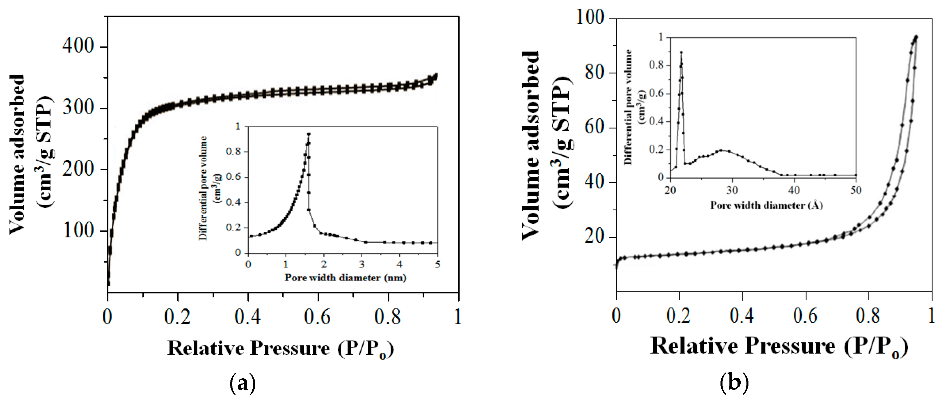
To quantify the surface area, the nitrogen (N2) physisorption measurements for SiNS and HNS are presented in Figure 3. According to the International Union of Pure and Applied Chemistry (IUPAC) classification, the isotherms in Figure 3a for SiNS are of a typical type I, which is significant for highly microporous materials. The primary adsorption occurred at the low relative pressure of P/P0 < 0.1, with the absence of a more rounded ‘knee’ indicating that the pore sizes were narrowed. As can be seen in Figure 3b, HNS exhibits a typical type-IV isotherm with H3-type hysteresis loop at the high relative pressure of P/P0 > 0.6, which is significant for the mesopores networks, while the H3-type hysteresis loop is attributed to slit-shaped pores. Based on the measurements, the calculated Brunauer–Emmett–Teller (BET) surface area for SiNS and HNS was experimentally determined to be 538.74 and 20.04 m2/g. The results are consistent with other works for producing SiNS and HNS from biomaterials templates [12]. Furthermore, the average pore diameters for SiNS and HNS were determined based on the BJH model to be 1.6 and 2.2 nm, respectively as shown in the inset in Figure 3. The surface area characteristics are summarized in Table 1.
Based on the morphology and physisorption measurements, it is suggested that the present of RS acts as a template that effectively facilitates the formation of SiNS and HNS for nanostructured silica and hematite, respectively. The presence of RS not only gives ordered morphology but also aided the formation of porosity in both SiNS and HNS.
3. Materials and Methods
All reagents used in the study were used as received from analytical grade reagents.
3.1. Preparation of Nanostructured Silica (SiNS)
SiNS were synthesized according to a calculated sol-gel composition of TEOS:H2O:HCl:CH3CH2OH at 1:4:0.01:3. Firstly, TEOS was added to an alcoholic acidified solution in the presence of HRS (38 wt %) at 60 °C for 6 h to produce SG-HRS. The SG-HRS was then calcined at 550 °C to give the opal-white color of SiNS.
3.2. Preparation of Nanostructured Hematite (HNS)
HNS was synthesized according to a calculated composition of H2O:HCl:RS:FeSO4·7H2O at 1:0.002:1:4. Firstly, an appropriate amount of FeSO4·7H2O, HCl and RS were added to double distilled water, heated to 70 °C and constantly stirred for 1 h. Then, the mixtures were left to room temperature before being filtered, washed with double distilled water and dried in an oven at 100 °C for overnight to produce a dark paste of RS-HNS. Subsequently, the RS-HNS was heated to 700 °C (heating rate of 5 °C/min) and maintained, before slowly cooled to room temperature. Finally, the powder was treated with concentrated HCl, before the samples were finally dried and collected as reddish-brown powder which is referred to as HNS.
3.3. Characterization
The morphology of particles was observed using field emission scanning electron microscopy (FESEM, JSM-6700F, JEOL, Tokyo, Japan). The nitrogen adsorption-desorption measurement was performed using AUTOSORB-1 Quantachrome volumetric adsorption analyzer by using nitrogen as the adsorbate at 77.35 K for full-scale adsorption-desorption isotherms (Boynton Beach, FL, USA). The samples were degassed at 363 K for 3 h and held at 433 K for 12 h before analysis. A Barrett–Emmett–Teller (BET) model was used to calculate the specific surface area and a Barrett–Joyner–Halenda (BJH) model was used to calculate the pore volume distribution and the average pore size.
4. Conclusions
In summary, the nanostructured silica and hematite were successfully prepared using rice starch by a template-assisted synthesis. The SiNS showed a pseudo-spherical morphology with a nano-size from 13 to 22 nm, and surface area of 538.74 m2/g. On the other hand, the HNS showed a spherical-shaped morphology with a nano-size from 24 to 48 nm, and surface area of 20.04 m2/g. In the future, both synthesized SiNS and HNS could be used as a potential nano-catalysts owing to the ordered morphology and porous networks that facilitate optimum charge transfers process.
Acknowledgments
This work was financially supported by Universiti Teknologi Mara (UiTM, Malaysia) under research grants cost centre No. 600-IRMI-Dana KCM 5/3/LESTARI (118/2017) and No. 600-UiTMSEL (PI. 5/4) (044/2018).
Conflicts of Interest
The author declares no conflict of interest.
References
- Zhu, H.; Jing, Y.; Pal, M.; Liu, Y.; Liu, Y.; Wang, J.; Zhang, F.; Zhao, D. Mesoporous TiO2@N-doped Carbon Composite Nanospheres Synthesized by the Direct Carbonization of surfactants After Sol–gel Process for Superior Lithium Storage. Nanoscale 2017, 9, 1539–1546. [Google Scholar] [CrossRef]
- Ghiyasiyan-Arani, M.; Salavati-Niasari, M.; Masjedi-Arani, M.; Mazloom, F. An Easy Sonochemical Route for Synthesis, Characterization and Photocatalytic Performance of Nanosized FeVO4 in the Presence of Aminoacids as Green Capping Agents. J. Mater. Sci. Mater. Electron. 2018, 29, 474–485. [Google Scholar] [CrossRef]
- Zheng, Y.; Huang, Y.; Abbas, Z.M.; Benicewicz, B.C. One-Pot Synthesis of Inorganic Nanoparticle Vesicles Via Surface-Initiated Polymerization-Induced Self-Assembly. Polym. Chem. 2017, 8, 370–374. [Google Scholar] [CrossRef]
- Kothary, P.; Dou, X.; Fang, Y.; Gu, Z.; Leo, S.Y.; Jiang, P. Superhydrophobic Hierarchical Arrays Fabricated by a Scalable Colloidal Lithography Approach. J. Colloid Interface Sci. 2017, 487, 484–492. [Google Scholar] [CrossRef] [PubMed]
- Hyodo, T.; Fujii, E.; Ishida, K.; Ueda, T.; Shimizu, Y. Microstructural Control of Porous In2O3 Powders Prepared by Ultrasonic-Spray Pyrolysis Employing Self-Synthesized Polymethylmethacrylate Microspheres as a Template and Their NO2-Sensing Properties. Sens. Actuators B Chem. 2017, 244, 992–1003. [Google Scholar] [CrossRef]
- Syoufian, A.; Inoue, Y.; Yada, M.; Nakashima, K. Preparation of Submicrometer-Sized Titania Hollow Spheres by Templating Sulfonated Polystyrene Latex Particles. Mater. Lett. 2007, 61, 1572–1575. [Google Scholar] [CrossRef]
- Hao, N.; Jayawardana, K.W.; Chen, X.; Yan, M. One-Step Synthesis of Amine-Functionalized Hollow Mesoporous Silica Nanoparticles as Efficient Antibacterial and Anticancer Materials. ACS Appl. Mater. Interfaces 2015, 7, 1040–1045. [Google Scholar] [CrossRef] [PubMed]
- Zan, G.; Wu, Q. Biomimetic and Bioinspired Synthesis of Nanomaterials/Nanostructures. Adv. Mater. 2016, 28, 2099–2147. [Google Scholar] [CrossRef] [PubMed]
- Matmin, J.; Affendi, I.; Endud, S. Direct-Continuous Preparation of Nanostructured Titania-Silica Using Surfactant-Free Non-Scaffold Rice Starch Template. Nanomaterials 2018, 8, 514. [Google Scholar] [CrossRef] [PubMed]
- Zhang, B.; Davis, S.A.; Mann, S. Starch Gel Templating of Spongelike Macroporous Silicalite Monoliths and Mesoporous Films. Chem. Mater. 2002, 14, 1369–1375. [Google Scholar] [CrossRef]
- Otero-de-la-Roza, A.; Mallory, J.D.; Johnson, E.R. Metallophilic Interactions from Dispersion-Corrected Density-Functional Theory. J. Chem. Phys. 2014, 140, 18A504. [Google Scholar] [CrossRef] [PubMed]
- Wu, C.; Wang, J.; Hu, Y.; Zhi, Z.; Jiang, T.; Zhang, J.; Wang, S. Development of a Novel Starch-Derived Porous Silica Monolith for Enhancing the Dissolution Rate of Poorly Water Soluble Drug. Mater. Sci. Eng. C 2012, 32, 201–206. [Google Scholar] [CrossRef]
Figure 1.
Preparation method for Route 1 of nanostructured silica (SiNS) and Route 2 of nanostructured hematite (HNS).
Figure 1.
Preparation method for Route 1 of nanostructured silica (SiNS) and Route 2 of nanostructured hematite (HNS).

Figure 2.
Field Emission Scanning Electron Microscopy (FESEM) micrograph for: (a) SiNS; (b) HNS.

Figure 3.
Physisorption measurements for (a) SiNS and (b) HNS. Inset represent Barrett, Joyner and Halenda method (BJH) models.
Figure 3.
Physisorption measurements for (a) SiNS and (b) HNS. Inset represent Barrett, Joyner and Halenda method (BJH) models.

Table 1.
Physisorption measurements data for SiNS and HNS.
| Sample | Surface Area (m2/g) | Pore Diameter (nm) |
|---|---|---|
| SiNS | 538.74 | 1.6 |
| HNS | 20.04 | 2.2 |
© 2018 by the author. Licensee MDPI, Basel, Switzerland. This article is an open access article distributed under the terms and conditions of the Creative Commons Attribution (CC BY) license (https://creativecommons.org/licenses/by/4.0/).
Share and Cite
MDPI and ACS Style
Matmin, J. Rice Starch-Templated Synthesis of Nanostructured Silica and Hematite. Proceedings 2019, 3, 1. https://doi.org/10.3390/IOCN_2018-1-05491
AMA Style
Matmin J. Rice Starch-Templated Synthesis of Nanostructured Silica and Hematite. Proceedings. 2019; 3(1):1. https://doi.org/10.3390/IOCN_2018-1-05491
Chicago/Turabian StyleMatmin, Juan. 2019. "Rice Starch-Templated Synthesis of Nanostructured Silica and Hematite" Proceedings 3, no. 1: 1. https://doi.org/10.3390/IOCN_2018-1-05491