Proceeding Paper

A Character Validation Proposal for High-Speed Visual Monitoring of Expiration Codes on Beverage Cans †

by
José Carlos Rodríguez-Rodríguez
,
Gabriele Salvatore de Blasio
,
Carmelo R. García
and
Alexis Quesada-Arencibia
*
Institute for Cybernetics, University of Las Palmas de Gran Canaria, Campus de Tafira, 35017 Las Palmas de Gran Canaria, Spain
*
Author to whom correspondence should be addressed.
Presented at the 13th International Conference on Ubiquitous Computing and Ambient Intelligence UCAmI 2019, Toledo, Spain, 2–5 December 2019.
Proceedings 2019, 31(1), 56; https://doi.org/10.3390/proceedings2019031056
Published: 21 November 2019

Abstract

:
Character recognizers have generally focused on printed text on paper with an emphasis on generality rather than speed. This makes the proposed algorithms not applicable in the context of the very high-speed industrial validation of expiration codes printed on the metal surface of a can. The extreme demands of speed and the adverse effects of lighting and movement, among other things, make it necessary to develop an original and specific strategy. The strategy presented in this paper first selects which of the segmented shapes of a printed can are the best candidates for comparison with expected characters. This is followed by a technique based on the comparison of templates (templates matching), which we call “morphologies”, and are represented as bitmaps to take advantage of the hardware capabilities of general-purpose processors. The use of templates has the advantage of avoiding the construction of a feature vector. In an acquisition test in a real industrial plant, we have been able to successfully treat 438 cans in 44 s, with only one validation error in one character, achieving a compromise between speed and quality that is sufficient for industrial validation in the conditions cited.

1. Introduction

This paper is a continuation of a previous work, “A Character Segmentation Proposal for High-Speed Visual Monitoring of Expiration Codes on Beverage Cans” [1]. In the aforementioned work, an industrial validator of expiration codes printed on aluminum or tin cans, called MONICOD, was presented in all its stages except the last one. This last stage (the character validation) is presented for the first time in this paper.
MONICOD is a machine vision solution [2] for the validation of expiration codes stamped on the aluminum or tinplate bottom of the cans [3,4]. The critical characteristic that defines this system is the very high speed of execution to ensure a validation cadence according to the requirement of a production line. It operates at 200 frames per second in order to validate up to 35 cans per second. (see Figure 1). In this context, validating means verifying whether or not the expiration code is correct. In addition to this requirement, MONICOD has to deal, among other difficulties, with the reflective properties of the metal surfaces of moving cans, which cause glitter that can hide the printed code.
MONICOD carries out the work of code validation from the acquisition of frames in different phases:
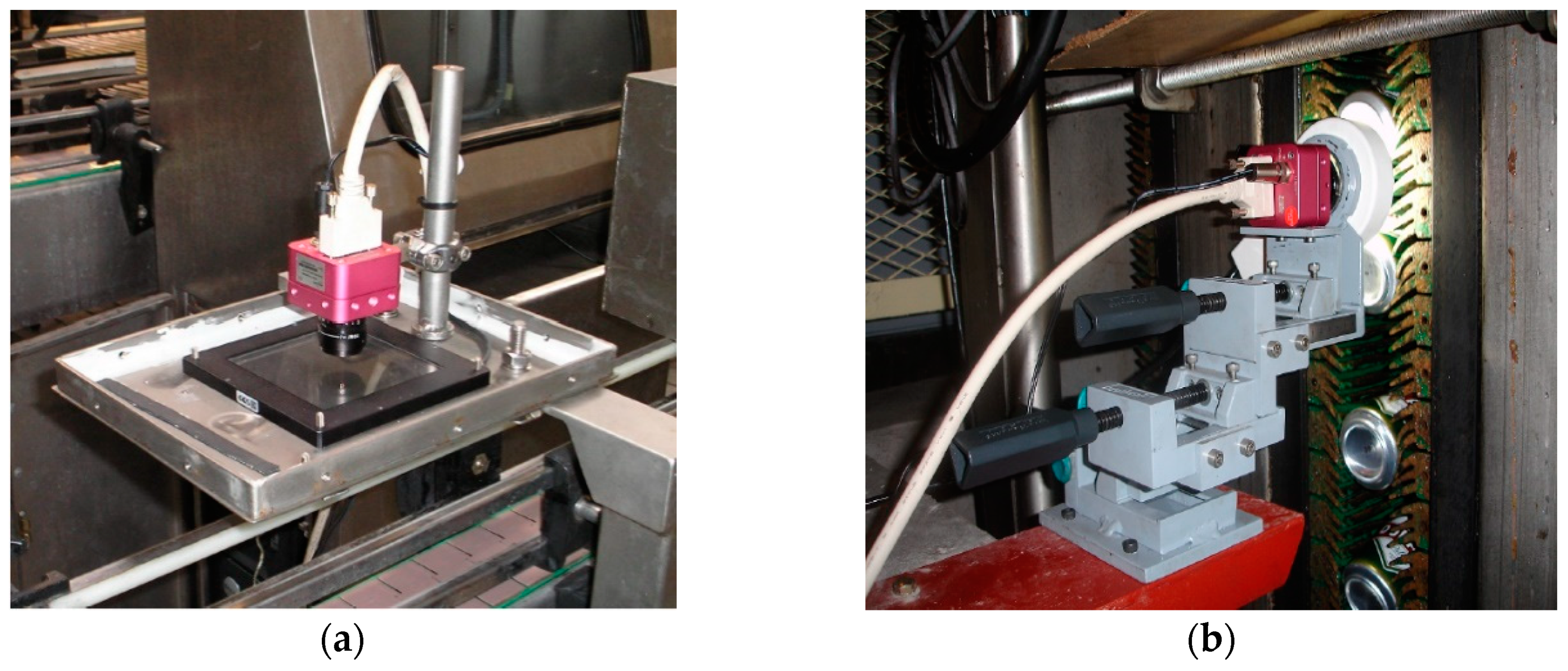
  • Selection of the best frame and area of interest, obtained in the transit of the can for code validation (see Figure 2). The area of interest is the region at the bottom of the can where the expiration code is printed.
  • Enhancement and equalization [5,6] of the area of interest (see Figure 3a).
  • Character segmentation.
    • Separation of ink and background (see Figure 3b) and grouping into ink fragments by threshold selection and flooding technique [7,8,9,10].
    • Organization of ink fragments into text lines (see Figure 3c).
    • Grouping of ink fragments into characters (see Figure 3d).
The purpose of these stages is to extract the information from the image that will be effectively validated (see Figure 4). The objective of this work is to present the last stage of MONICOD processing, which is the validation of codes.

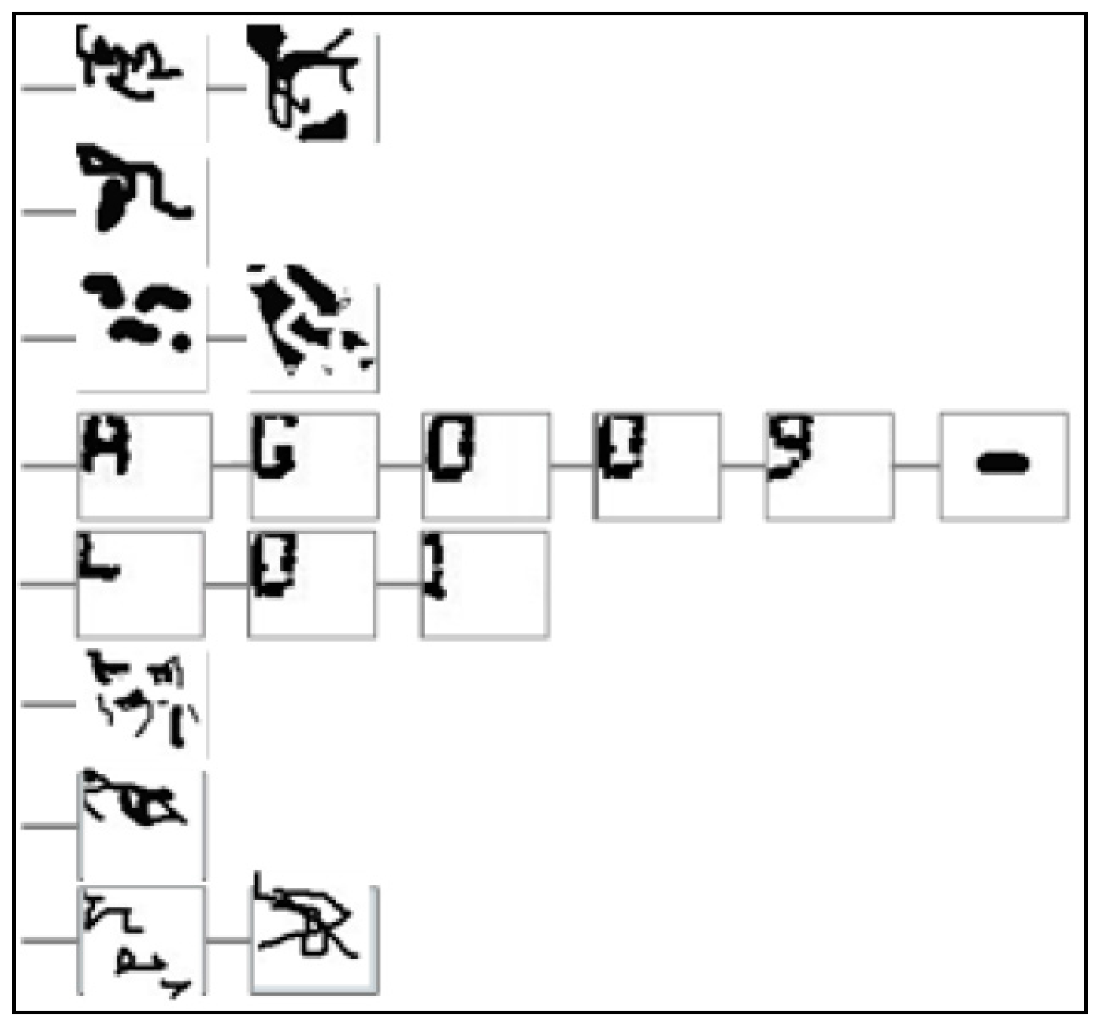
2. Acquired Shapes and Expected Code

The previous stages provide us with a set of candidate characters that we generically call “shapes”. These characters are arranged in bands (from top to bottom) and, within a band, from left to right, as shown in Figure 4. A shape may or may not be a valid character, but all valid characters are shapes.
On the other hand, the “expected” code is updated every time a code validation is carried out. The expected code update is mainly based on the current date and time. Based on these data and the type of product, the expiration date is calculated.
The semantics of each character of the expiration code has no interest for the validation itself, but rather for its generation/update. Another factor to consider is the importance of each character to know if a failure in its validation is critical or not.

3. Validation and Recognition

The description of the problem, requirements, constraints, and input data fit perfectly with a validation problem, and so, and for the sake of speed, MONICOD is a validator. This is particularly important in the work presented here.
“Validate” does not necessarily imply “recognize”: by validating, we know beforehand and for sure what is expected to be stamped; otherwise, we would not be able to validate the imprint. This scenario is not the typical one faced by a recognizer, which tries to unravel the printed text without the knowledge of what may be there.
Since the validator has that knowledge, it can fine-tune its procedures, and even stop in the middle of the procedure as soon as there is an indication that what has been obtained does not correspond to what was expected. This is why validation is potentially faster than recognition.
Verification consists of comparing the acquired (segmented) code found in the image with the expected code generated internally by MONICOD (which is always assumed to be correct).
If recognition was used for validation, the procedure would be:
  • Recognize the text.
  • Compare the recognized text with the expected text.
  • Give a decision from the comparison.
MONICOD does not carry out a recognition when validating the character, in the sense that it is not a question of determining which class it corresponds to, but whether or not it corresponds to a particular expected class. In the validation, the procedure would be:
  • Compare the extracted shapes with the expected shapes.
  • Give a decision from the comparison.

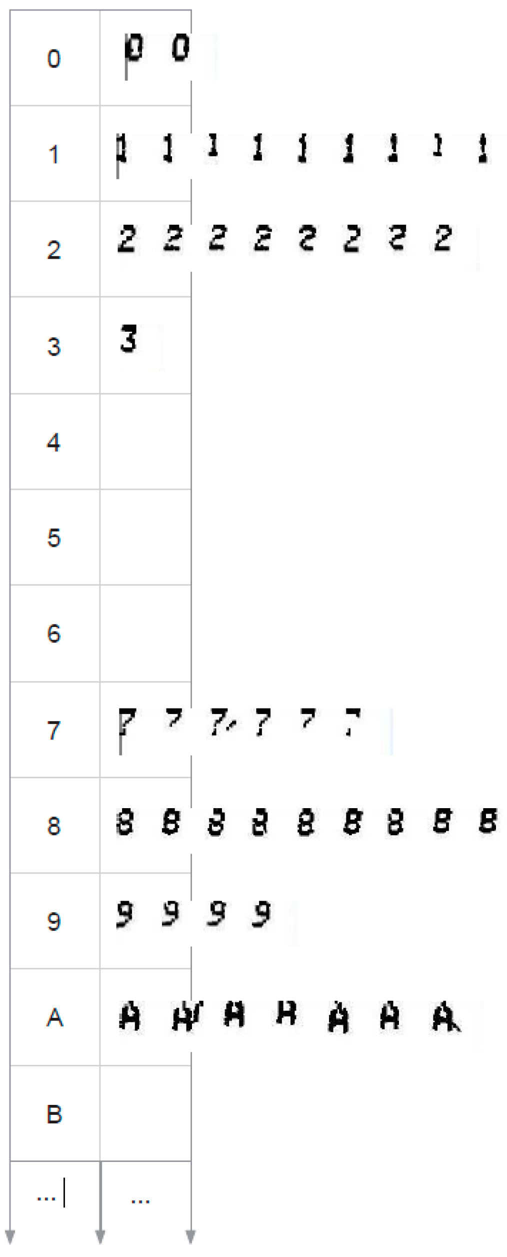
4. Morphologies, Morphological Families, and the Morphological Family Base

4.1. Morphologies

MONICOD bases its validation on the shape of the characters. To that end, it makes an extraction of basic characteristics of the shape. It compares the discretized shape with discretized character shapes that are entirely stored and retrieved in the character Morphological Family Base (MFB). MONICOD refers to these shapes contained in the MFB of characters as ‘morphologies’.
The morphology is the minimum unit of the MFB of characters. It is actually a binary template. Its structure is simple: it consists of a discrete and uncompressed representation of zeros and ones of dimension m x n. By convention, ‘zero’ (0) represents non-ink, and ‘one’ (1) represents ink. The relative positions of zeros and ones (ink and non-ink) maintain the same relationship as in the shape they represent. Thus, morphology is an explicit representation of binarized real-size shapes. It can be seen as a map of bits or cells being susceptible to their treatment with bit operations (see Figure 5). This accelerates the computation enormously.
Morphologies offer the following advantages:
  • If the shapes are legible and recognizable, the associated morphologies will retain those qualities.
  • Morphologies are extracted directly from segmentation without any analysis involving new operations such as the creation of a vector of characteristics [11,12,13,14,15,16,17,18,19].
  • Industrial printing standardizes. It is expected that printed characters will be similar between cans and can be associated with the same morphology.

4.2. Distance between Two Morphologies

The most important action that can be done on a morphology is to compare it directly with another morphology and evaluate how much distance or similarity exists between them. It is the approximation known as template comparison or template matching.
It is necessary for MONICOD to carry out this operation as quickly as possible. For example, the Euclidean distance would be computationally too expensive. MONICOD defines its own distance between morphologies from the simple count (counting ones (or zeros) is a bit-level operation, identical to the scalar product between templates) of matches and non-matches in ink and background between the cells of two morphologies A and B. The values of the counters allow a simple evaluation of similarity.
For two morphologies to be comparable, they must have the same height and width (m and n). Four independent counters are used. Comparing A and B:
  • Ink Coincidences (IC): Counts ink coincidences between A and B.
  • No-Ink Coincidences (NIC): Count background coincidences between A and B.
  • Absent Ink (AI): Counts non-coincidences due to absent ink in B that is present in A.
  • Unexpected Ink (UI): Counts non-coincidences due to ink present in B that is not present in A.
If we exchange operands A and B to B and A, the magnitudes of the AI and UI counters are exchanged, while the NIC and IC counters remain the same. It is always fulfilled that:
N I C + A I + U I + I C = m   x   n
IC + AI corresponds to the amount of ink in A, and NIC + UI corresponds to the amount of no-ink or background in A.
The comparison methodology comprises two sub-phases. The first is limited to carry out a count of similarities and differences, cell by cell, between the stored template and the acquired template. The position within the template is not considered. The second computes a function that is parameterized by the count values of the first phase, which gives us a measure of similarity:
1 M A , B   w i t h   M A , B = 1 2 A · B A + A ¯ · B ¯ A ¯ ,
where A and B correspond to the expected and extracted template, respectively. X and X are the number of ones and zeros in vector X , respectively. Thus, A · B is the number of ones of the scalar product of vectors A and B. The denominators in Equation (2) are fixed and can be pre-calculated, which accelerates the calculation of the distance expression.

4.3. Morphological Families

In an ideal situation, a unique way to identify a character would be enough because it would be associated with a single character in an unambiguous way. It would be sufficient to compare the acquired shape with an artificially generated shape decided by the automatic code generator and determine if there is a match or not. This approach seems to make sense if we take into account that we are always printing with the same machine on surfaces of the same type. However, in practice, it is found that the acquired shapes do not present the expected uniformity (see Figure 6). There are several reasons for this: the printer does not have the same effectiveness in each print, the acquisition has differences due to changes in lighting, etc.
The morphological family is a logical grouping of morphologies that responds to the fact that each character is associated with a set or collection of equal valid shapes (see Figure 7).
The properties of a morphological family are:
  • No repetition: There are never two identical morphologies within a morphological family.
  • Relationship: All the morphologies have more similarity with any of the morphologies of its own family than with any other morphology belonging to another family (see Section 4.2).

4.4. Morphological Family Base (MFB)

The MFB contains the characters learned by MONICOD and manages recoveries, additions, and deletions (see Figure 8). The Morphological Family Base is maintained, consulted, and modified in memory: this way, we do not access the disk to rescue or update data. It can also be restarted to start a new learning from scratch.
The Morphological Family Base makes it possible to learn and validate characters, and if necessary, also recognition; however, MONICOD, as has been said, is not a recognition system.
The MFB operates with two key concepts: morphologies and morphological families.
The fundamental operations on the MFB that are possible to carry out both in validation time and learning time are the addition of a new morphology, suppression of a morphology, and sequential query of morphologies contained in a given morphological family.

5. Code Validation

There are three stages in the validation phase. The first stage is reduced to choosing which expected character we will compare with what acquired character: that is to say, to select the comparison pair. The second stage consists of the comparison itself: deciding whether the acquired character and the expected character are sufficiently similar or not. The third stage makes a global analysis of the code comparison and judges whether, with the positively validated characters, the code can be considered good or not.

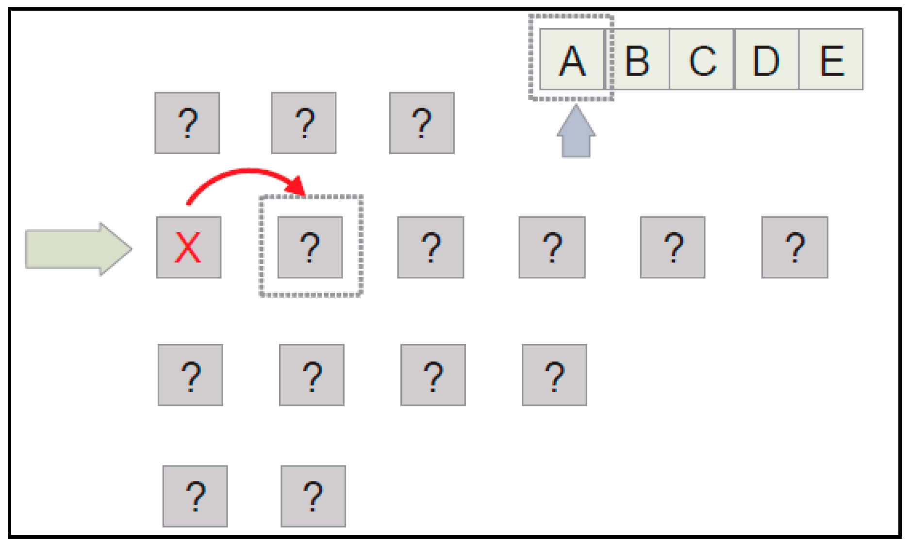
5.1. Selection of Comparison Pair

The pair selection policy requires that:
  • The searched characters are in the can.
  • The next expected character is not examined until the current one has been found.
  • If the acquired character does not correspond to the expected one, it will be assumed that the acquired character is noise and the system will advance to the next acquired character (but the expected character remains fixed).
The comparison is carried out character by character. This comparison maintains the Western reading order of the characters in the code to be validated: from left to right, from top to bottom.
Proceeding in this way offers several advantages:
  • When reading from left to right, we have useful information to refine clusters of ink fragments, and we always leave complete characters behind. So, if the current grouping does not correspond to a character, the only alternative is to consider possible mergers with the grouping to the right.
  • In the expiration codes, it seems that the importance of the characters decreases from left to right and from top to bottom; that is, within a line, a character is more likely to have equal or greater importance than the immediate character to its right. If the code is going to be negatively validated, it is better to know it as soon as possible, and giving priority to the important characters makes us advance in that purpose. This rule is fulfilled in all the studied codes.
  • It is more likely that a line has greater or equal importance than that which is immediately lower. In all the studied codes (two lines), this rule is met.
The procedure follows these steps:
  • The first line of the expected code not yet processed is selected in the order from top to bottom. If there are no expected lines to be processed, we go to the stage described in Section 5.3.
  • We choose, within the bands of acquired shapes, the one that may contain the expected line selected in step 1. It will be done from top to bottom starting from the next band after the last band successfully verified. The rule to be fulfilled is that the selected band has the same or greater number of shapes than the number of characters of the expected code line (see Figure 9).
  • Within the selected expected line, we select the first expected character not yet verified from the expected code following the order from left to right. If all the characters have already been validated, then the expected line has already been completely processed, and therefore, we return to step 1.
  • Within the band of acquired shapes, we select the first acquired shape not yet treated. If there are no acquired shapes, it is necessary to select another band, so all the expected characters verified in this line become unverified, and we return to step 2.
  • Verification is made between the morphological family of the expected character and the acquired shape (see Section 5.2).
    • The verification is negative: The current acquired shape is merged with the immediately following one and the verification between the morphological family of the expected character and the new shape, as the result of the described merging process, is repeated (see Figure 10 and Section 5.2),
      • Verification is positive: We consider the current and the next acquired shape as treated. The expected character is marked as verified. Go back to step 3.
      • The verification is negative. We consider the current acquired shape as noise. We mark it as treated (see Figure 11). Go back to step 4.
    • The verification is positive: The acquired shape is marked as treated. The expected character is marked as verified (see Figure 12). Go back to step 3.

5.2. Matching

This stage comprises three well-differentiated phases:
  • The morphological family corresponding to the expected character is recovered from the MFB. The family must exist, and there must be morphologies within that family. Otherwise, we will face a critical failure in the validation, which should be notified to the operator immediately.
  • The morphologies of the morphological family are recovered one by one. Each morphology is compared with the acquired shape. This comparison includes two tests:
    • Comparison of the amount of ink present. It is a previous filtering. The ink difference between the morphology and the acquired character is compared. A difference above a permissible maximum ink difference threshold makes it unnecessary to carry out a template matching. If it passes the ink covered area test, the second test is applied. Otherwise, it is stated that they are different. The similarity value in that case is 0.
    • Templates matching. A comparison of templates is made using the distance between morphologies described in Section 4.2 to evaluate the similarity between the morphology and the acquired character. The similarity value (distance) obtained is stored.
  • Finally, the maximum similarity value obtained in the previous phase is chosen when facing all the morphologies of the morphological family with the acquired character. If it exceeds a certain threshold, the verification has been positive. Otherwise, it is negative. This result feeds the code validation resolution.

5.3. Validation Resolution

In this phase, it is determined whether the can is valid (positive validation) or not (negative validation). To make this decision, the system will work with:
  • Which expected characters have been verified positively (in position and line) in the acquired can image. The procedure described in the previous sections provides this information.
  • Which characters are important. The user has previously provided the system with this information through a configuration file.
The policy followed is: If all important characters are present in the can in the expected line/order, the expiration date printout is valid. Otherwise, the expiration date printout is not considered valid. MONICOD just updates a statistics of total, positive, and negative validated cans and launches a warning message in the case of a negative validation. The processing of this warning message goes beyond MONICOD and becomes the responsibility of the operator. If the validation is positive, it is expected that no action will be taken. On the other hand, if the validation is negative, different actions may be triggered: removing the affected can manually or mechanically, stopping the line to solve a chronic problem (it may be necessary, for example, to recalibrate the system...), ignoring the negative validation, etc.

6. Results

The expiration code validation algorithm described is integrated in MONICOD, which comprises several phases and stages. A test of the system has been carried out consisting of treating 8884 frames containing 465 cans, all of them correctly labeled with the expiration code. The total duration of the test was 44.42 s. MONICOD was able to process 200 images per second without requiring specific hardware.
The quality of the results obtained is detailed in Table 1, while Table 2 shows the causes of the failures. In the end, in the whole experiment there was only one validation failure with one character: It was marked as incorrect when it was actually correct.
As mentioned in the Section 1 Introduction, a frame does not go through all the phases. In fact, the frames that reach the validation phase are only those that show a perfectly centered can. As shown in Figure 13, the validation algorithm consumed less time than the other MONICOD phases during this test.

7. Conclusions and Future Works

The final phase of the current implementation of MONICOD has been presented: A character validator based on a template-matching scheme.
Considering the overall results, the algorithm broadly meets the required speed specifications. This has been possible due to the application of several strategies. First, there is the use of a template matching method. The template is a direct and immediate result of the segmentation, which keeps all the information of the shape, and makes it possible to omit a feature-extraction process. Second, there is the application of bit operations to perform template matching. Bit operations are supported at a low level by low-cost general-purpose processors, forming an inherent part of their architecture, so we guarantee great compatibility as well as great speed. Third, comparisons filtering is applied: It is only compared when it has been noticed that the amount of ink (that is achieved applying a bit-level operation consisting of counting 1 s) between the morphologies to be compared is approximately similar. If this is not the case, the similarity is estimated to be zero.
An important weakness of the algorithm is that it does not offer a good generalization. The construction of a good base of morphologies is key to alleviate this problem. In future works, we will study the learning mechanisms that allow the aforementioned construction to be automated, as well as a comparison with other techniques such as k-Nearest Neighbor KNN [20], neural networks [21], and support vector machines [22,23].

Acknowledgments

The authors wish to express their gratitude to the Computer Science Department of the University of Las Palmas de Gran Canaria, Compañía Embotelladora de Canarias, S.A. (Canary Bottling Company, Las Palmas de Gran Canaria, Spain) and to Compañía Cervecera de Canarias, S.A. (Canary Brewing Company, Las Palmas de Gran Canaria, Spain).

References

  1. Rodríguez-Rodríguez, J.C.; Quesada-Arencibia, A.; Moreno-Díaz, R., Jr.; García, C.R. A Character Segmentation Proposal for High-Speed Visual Monitoring of Expiration Codes on Beverage Cans. Sensors 2016, 16, 527. [Google Scholar] [CrossRef] [PubMed]
  2. Cheriet, M.; Kharma, N.; Liu, C.-L.; Suen, C.Y. Character Recognition Systems: A Guide for Students and Practitioners, 1st ed.; Wiley-Interscience: New York, NY, USA, 2007; pp. 5–128. [Google Scholar]
  3. Rodriguez-Rodriguez, J.C.; Quesada-Arencibia, A.; Moreno-Diaz, R., Jr. Industrial Vision Systems, Real Time, and Demanding Environment: A Working-Case for Quality Control. In Vision Systems. Applications; Obinata, G., Dutta, A., Eds.; I-Tech Education and Publishing: Vienna, Austria, 2007; pp. 407–422. [Google Scholar]
  4. Rodriguez-Rodriguez, J.C. MONICOD: Supervisión Visual a Muy Alta Velocidad de Codificación Impresa Industrial (Visual Monitoring for Ultra High Speed Printed Industrial Coding). Ph.D. Thesis, Universidad de Las Palmas de Gran Canaria, Las Palmas de Gran Canaria, Spain, 2013. [Google Scholar]
  5. Saradhadevi, D.V.V. A survey on digital image enhancement techniques. Int. J. Comput. Inf. Sci. 2010, 8, 173–178. [Google Scholar]
  6. Zhu, H.; Chan, F.H.Y.; Lam, F.K. Image contrast enhancement by constrained local histogram equalization. Comput. Vis. Image Und. 1999, 73, 281–290. [Google Scholar] [CrossRef]
  7. Sezgin, M.; Sankur, B. Survey over image thresholding techniques and quantitative performance evaluation. J. Electron. Imaging 2004, 13, 146–165. [Google Scholar]
  8. Otsu, N. A threshold selection method from gray-scale histogram. IEEE Trans. Syst. Man Cybern. 1979, 9, 62–66. [Google Scholar] [CrossRef]
  9. Kittler, J.; Illingworth, J. Minimum error thresholding. Pattern Recogn. 1986, 19, 41–47. [Google Scholar] [CrossRef]
  10. Haralick, R.M.; Shapiro, L.G. Image segmentation techniques. Comput. Gr. Image Process. 1985, 29, 100–132. [Google Scholar] [CrossRef]
  11. Spiliotis, I.M.; Mertzios, B.G. Real-time computation of two-dimensional moments on binary images using image block representation. IEEE Trans. Image Process. 1998, 7, 1609–1615. [Google Scholar] [CrossRef] [PubMed]
  12. Papakostas, G.A.; Karakasis, E.G.; Koulouriotis, D.E. Efficient and accurate computation of geometric moments on gray-scale images. Pattern Recogn. 2008, 41, 1895–1904. [Google Scholar] [CrossRef]
  13. Kotoulas, L.; Andreadis, I. Accurate Calculation of Image Moments. IEEE T. Image Process. 2007, 16, 2028–2037. [Google Scholar] [CrossRef] [PubMed]
  14. Yap, P.-T.; Paramesran, R.; Ong, S.-H. Image analysis using Hahn moments. IEEE T. Pattern Anal. 2007, 29, 2057–2062. [Google Scholar] [CrossRef] [PubMed]
  15. Kotoulas, L.; Andreadis, I. Image analysis using moments. In Proceedings of the 5th Int. Conf. on Technology and Automation, Thessaloniki, Greece, 15–16 October 2005; pp. 360–364. [Google Scholar]
  16. Abdul-Hameed, M.S. High order multi-dimensional moment generating algorithm and the efficient computation of Zernike moments. In Proceedings of the 1997 IEEE International Conference on Acoustics, Speech, and Signal Processing, Munich, Germany, 21–24 April 1997; pp. 3061–3064. [Google Scholar]
  17. Hatamian, M. A real-time two-dimensional moment generating algorithm and its single chip implementation. IEEE Trans. Acoust. Speech 1986, 34, 546–553. [Google Scholar] [CrossRef]
  18. Dalhoum, A.L.A. A comparative survey on the fast computation of geometric moments. Eur. J. Sci. Res. 2008, 24, 104–111. [Google Scholar]
  19. Di Ruberto, C.; Morgera, A. A comparison of 2-d moment-based description techniques. In Proceedings of the 13th International Conference on Image Analysis and Processing ICIAP 2005, Cagliari, Italy, 6–8 September 2005; Roli, F., Vitulano, S., Eds.; Springer-Verlag: Berlin/Heidelberg, Germany, 2005; pp. 212–219. [Google Scholar]
  20. Arya, S.; Mount, D.M.; Netanyahu, N.S.; Silverman, R.; Wu, A.Y. An optimal algorithm for approximate nearest neighbor searching fixed dimensions. J. ACM 1998, 45, 891–923. [Google Scholar] [CrossRef]
  21. Haykin, S. Neural Networks and Learning Machines, 3rd ed.; Pearson Education: Upper Saddle River, NJ, USA, 2009; pp. 122–268. [Google Scholar]
  22. Burges, C.J.C. A tutorial on support vector machines for pattern recognition. Data Min. Knowl. Disc. 1998, 2, 121–167. [Google Scholar] [CrossRef]
  23. Cristianini, N.; Shawe-Taylor, J. An Introduction to Support Vector Machines and Other Kernel-Based Learning Methods, 1st ed.; Cambridge University Press: Cambridge, UK, 2000; pp. 93–124. [Google Scholar]
Figure 1. Image acquisition devices on a conveyor belt with a capacity for 200 captures per second (black and white) in a (a) horizontal plane and (b) vertical plane.
Proceedings 31 00056 g001
Figure 2. Selection of the best snapshot for a can. The best snapshot is the one where the can appears centered.
Proceedings 31 00056 g002
Figure 3. (a) Enhancement and equalization of the area of interest. (b) Separation of ink and background. (c) Organized ink fragments into text lines. (d) Grouping the ink fragments into characters.
Proceedings 31 00056 g003
Figure 4. Information obtained in the previous phases.
Proceedings 31 00056 g004
Figure 5. The representation of morphology in three parts. (a) The binarized shape. (b) A matrix of zeros and ones corresponding to (a). (c) The matrix. (b) The matrix arranged as a vector, which is how MONICOD works internally. This last representation is called a template. MONICOD: a machine vision solution for the validation of expiration codes stamped on the aluminum or tinplate bottom of cans.
Proceedings 31 00056 g005
Figure 6. All the eights shown are legible and therefore acceptable. However, they are different from each other.
Proceedings 31 00056 g006
Figure 7. Morphological family for ‘A’.
Proceedings 31 00056 g007
Figure 8. Representation of the Morphological Family Base (MFB) of characters.
Proceedings 31 00056 g008
Figure 9. The expected line is “ABCDE”. It has five characters. We select, from top to bottom, the first band with enough acquired shapes to contain five characters.
Proceedings 31 00056 g009
Figure 10. Validation of the first expected character “A” with the first acquired shape of the band has failed. We build a new acquired shape by merging the first shape acquired with the one immediately following, and we repeat the validation.
Proceedings 31 00056 g010
Figure 11. Validation has failed again, so we consider the first shape of the band as noise, and move onto the next one. The expected character to be validated is still “A”.
Proceedings 31 00056 g011
Figure 12. We finally managed to successfully validate the “A” character. The acquired shape has been successfully treated. The expected character “A” has been verified. We move onto the next expected character not verified and the next acquired shape not treated for verification.
Proceedings 31 00056 g012
Figure 13. Pie chart that comparatively shows the total time consumed by each of the phases of MONICOD. The pink color represents the time dedicated to the validation algorithm (13%). The other phases are presented and described exhaustively in [1]. They are enhancement image (blue), equalization (light blue), band separation(green), ink association (red), and grouping (yellow).
Proceedings 31 00056 g013
Table 1. Quality evaluation of the test performed.
Total ValidationsSuccessful ValidationsFailures
46543827
Table 2. List of causes of test failures.
Number of FailuresPercentage
Failure in the selection of the best can1350.0%
Band division failure1142.3%
Grouping failure  13.8%
Failure in character validation  13.8%

