1. Introduction
The automatic creation of three-dimensional (3D) representations of objects, buildings, or scenarios using drones and artificial intelligence techniques is a current and highly relevant research field in the realm of artificial intelligence, specifically in computer vision. This work focuses on designing and developing an innovative system that integrates the use of drones and advanced computer vision techniques to facilitate the automated generation of point clouds and 3D meshes. The significance of this work lies in its ability to address significant challenges in multiple areas, such as infrastructure inspection and maintenance, the preservation of cultural heritage, urban planning and design, surveillance of unauthorized constructions, the observation of terrain modifications in natural disaster situations, assistance in forensic accident investigations, among others. Furthermore, this work aims to overcome the limitations of traditional methods, which are often slow and computationally expensive, by adapting and optimizing existing algorithms in the field of computer vision and artificial intelligence.
This work is framed within a context where various photogrammetry tools already exist for creating 3D models using drones. However, these tools employ manual and conventional processes that require a high computational demand, hindering their practical application in most challenges addressed by this field of research. Therefore, computer vision and artificial intelligence models developed by other researchers are used as a basis for processing the drone’s images. It is expected that the results of this research will significantly contribute to advancements in 3D model generation using drones. The main expected outcomes include the development of an integrated and efficient system for real-time image acquisition and 3D model generation, the improved accuracy and speed of 3D reconstruction, and a comprehensive evaluation of the performance and robustness of the proposed system in different environments and conditions, allowing for future enhancements and a deeper understanding of the capabilities and applications of drones in 3D model generation.
This manuscript provides a detailed description of the design and development process of the proposed system, starting with an exhaustive review of state-of-the-art developments in the fields of photogrammetry and computer vision, as well as the use of drones for the generation of 3D representation. The fundamental concepts related to the employed technologies and techniques are presented, along with a discussion of currently available commercial and open-source software and specialized libraries in computer vision and 3D reconstruction. This study poses the research question of how real-time 3D reconstruction can be achieved using images and videos captured by drones, employing state-of-the-art algorithms to obtain representations of a similar quality to those obtained using conventional techniques.
1.1. Aims of This Work
The main purpose of this research is to design and develop an innovative system that incorporates the use of unmanned aerial vehicles (drones) and sophisticated computer vision techniques to facilitate the automated generation of high-quality point clouds and three-dimensional (3D) meshes. This approach responds to the growing demand for more accurate and efficient technological tools for obtaining 3D models, which play a crucial role in a wide range of disciplines such as engineering, architecture, cartography, and topography. The implementation of this innovative system will significantly reduce the time and costs associated with 3D model creation, while improving their quality and accuracy through the synergy between drone technology and computer vision. Additionally, the proposed system aims to achieve a high level of automation, which will increase efficiency in the production of 3D models and allow for greater adaptability and flexibility under various capture conditions.
The overall objective of this research lies in the conception and development of an integrated system that leverages the advantages of drones and computer vision to automatically generate high-quality point clouds and 3D meshes. This approach seeks to optimize efficiency, precision, and cost reduction in acquiring 3D models used in multiple fields of application. Specifically, the following specific objectives (SO) are presented, which break down the overall objective into more precise and measurable goals. By achieving these specific objectives, the overall objective of this work will be accomplished.
The hypothesis of this research is as follows: The combination of state-of-the-art algorithms and drone technology enables real-time 3D reconstruction from captured images and videos, achieving a high-quality representation similar to that obtained using conventional techniques.
1.2. Concepts
1.2.1. Drones
A drone, also known as unmanned aerial vehicle (UAV) or unmanned aircraft system (UAS), is a flying apparatus that does not require a human pilot on board [
1]. These devices can be equipped with cameras, sensors, and other instruments, enabling them to perform a wide variety of tasks in both military and civilian domains. The most common type of drone is the multirotor drone (see
Figure 1 [
2]).
Drones are used in surveillance and reconnaissance missions, as well as for aerial attacks [
3]. They are also used for inspections of critical infrastructures (such as power lines or oil platforms), package deliveries, mapping and topography work, inspections, the mapping of mines, monitoring of crops and construction sites, and capture of images and videos for artistic or documentary purposes [
1]. There are various types of drones, which vary in design, size, and capabilities [
4,
5]. Multirotor drone can take off and land vertically [
6]. Drones are further classified into several subtypes depending on the number of rotors [
7]. Another type of drone is the fixed-wing drone, which often resembles conventional airplanes. These UAVs are generally larger than multirotors and are often used for surveillance and reconnaissance tasks across large areas [
8].
1.2.2. 3D Representations
Three-dimensional representations are geometric models that describe the shape and structure of an object or scene in three-dimensional space. This type of representation has experienced significant growth in recent decades due to technological advancements in the field of computer vision.
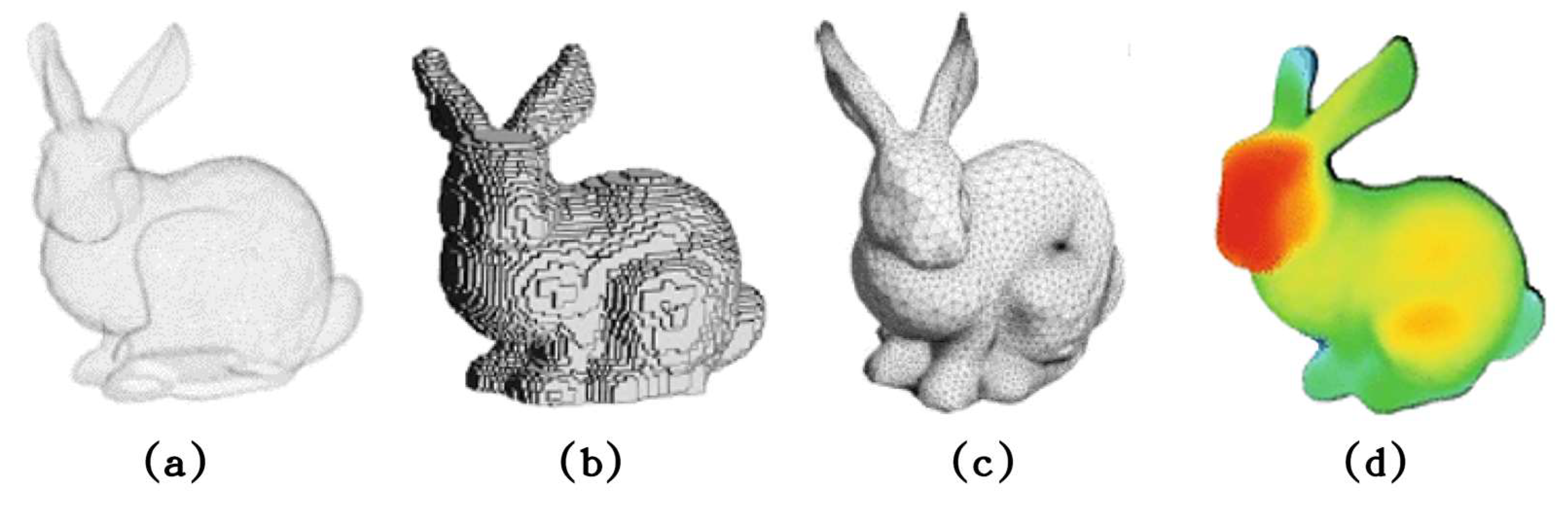
Figure 2 shows different types of representation used in the industry.
Three-dimensional representations allow objects or environments from the real world to be visualized and modeled in a three-dimensional virtual space, leading to a wide range of applications in various fields. The following are brief descriptions of the most common 3D representations [
10]:
Point clouds: Sets of points in 3D space that represent the surface of a scene. Each point may have additional attributes such as color (
Figure 2a [
9]).
Volumetric representations: They use a three-dimensional data structure, such as a set of voxels (3D pixels), to represent the volume and shape of a scene. This representation is particularly useful in medical and scientific applications. See
Figure 2b [
9].
Polygonal meshes: Set of vertices, edges, and faces that define the geometry of a 3D object. Polygonal meshes are typically composed of triangles or quadrilaterals connected to form the object’s surface. See
Figure 2c [
9].
Depth maps: Two-dimensional representations of the distance or depth of objects in a 3D scene with respect to a specific viewpoint. In a depth map, each pixel has a value indicating the distance between the viewpoint and the corresponding object in the scene. These depth values can be measured in distance units, such as meters, or in relative units, representing the disparity between two stereoscopic views. See
Figure 2d [
9].
1.2.3. Photogrammetry and 3D Reconstruction
Photogrammetry is a technique that allows the metric and geometric information of objects and scenes to be obtained from photographs or digital images. This information is used to generate maps, digital terrain models, three-dimensional models of objects and buildings, among others. Photogrammetry is based on triangulation and the measurement of angles and distances in images to determine the spatial coordinates of the points of interest [
11,
12]. On the other hand, 3D reconstruction is the process of generating a three-dimensional representation of a scene or object from a series of 2D images taken from different angles and positions. This process involves identifying common features in the images, estimating the position and orientation of the cameras, and constructing a 3D geometry of the scene [
13]. In this field, several commercial tools have been developed that use computer vision algorithms to transform images into maps and three-dimensional models. Some of these tools include Pix4D, Agisoft Metashape, ReCap Pro, ArcGIS Drone2Map, ContextCapture, DroneDeploy, and 3DF Zephir, which have become references in the industry due to their high integration with drones and wide range of features [
14,
15]. It is important to note that these programs have similar characteristics and functionalities but may also have some differences in terms of ease of use, accuracy of results, and licensing cost. On the other hand, open-source software tools are also becoming increasingly relevant in the context of photogrammetry and 3D reconstruction. Some notable tools are Meshroom and COLMAP, free open-source tools for creating and manipulating 3D models from images.
The combination of photogrammetry and 3D reconstruction with drone technology has allowed data to be captured in hard-to-reach areas for the generation of high-precision, three-dimensional models, revolutionizing the way that projects are carried out in various fields, such as archaeology [
16], natural resource management [
17], and urban planning [
18].
1.2.4. Multi-View Stereo (MVS)
Multi-view stereo (MVS) is an advanced computer vision technique that enables the three-dimensional reconstruction of a scene or object from multiple images taken from different viewpoints. Inspired by stereo vision, MVS extends this approach by utilizing several images captured from different angles and positions, resulting in a more precise and detailed 3D representation (see
Figure 3 [
19]). MVS algorithms employ correspondence and optimization techniques to identify and relate feature points in the images and estimate their three-dimensional position in space [
19].
Key features of MVS include depth estimation, feature correspondence, optimization, and 3D modeling. These capabilities allow MVS to generate highly accurate and detailed 3D models, while being more robust against occlusions, lighting changes, and correspondence errors [
20]. However, this technique presents challenges such as computational complexity and the need for proper camera calibration and orientation. MVS is currently applied in a wide range of fields and industries, including cartography and topography, archaeology and cultural heritage, robotics and autonomous vehicles, virtual and augmented reality, and inspection and quality control.
1.2.5. Simultaneous Localization and Mapping (SLAM)
Simultaneous Localization and Mapping (SLAM) is an advanced technique in robotics and computer vision that enables a robot or autonomous vehicle to build a map of its unknown environment while estimating its position and orientation in real time [
21]. SLAM addresses two fundamental problems in robotics and navigation: mapping the environment and localizing the robot or vehicle within that map. This technique combines data from various sensors such as cameras, LiDAR, and inertial sensors to provide accurate and robust estimates of the robot’s position and orientation, as well as map updates as new areas are explored [
22,
23].
Figure 4a [
24] shows the mapping of a room with the camera’s estimated position along its trajectory.
Figure 4b [
24] illustrates the mapping along a hallway. Key features of SLAM include localization, mapping, sensor fusion, filtering, and optimization. Regarding filtering and optimization, SLAM employs techniques such as an Extended Kalman Filter (EKF) and graph optimization. An EKF is a state estimation technique that enables the robot’s position and orientation to be updated in real time, while graph optimization is an approach that improves the consistency and accuracy of the map and position estimates over time [
25]. These capabilities enable SLAM to facilitate autonomous navigation in unknown environments, providing robustness against uncertainties, sensor data errors, and motion models. However, this technique presents challenges in terms of computational complexity, convergence, and the consistency of filtering and optimization algorithms.
SLAM has applications in a wide range of fields and industries, including mobile robotics, unmanned aerial vehicles (UAVs), autonomous vehicles, augmented and virtual reality, and underwater exploration and mapping. In these contexts, SLAM significantly contributes to the advancement of research and development in the field of robotics and autonomous navigation, enabling robots and vehicles to move and make decisions independently in unknown and dynamic environments. The implementation of filtering and optimization techniques, such as an EKF and graph optimization, is crucial for improving the accuracy and consistency of position estimates and the map in SLAM applications.
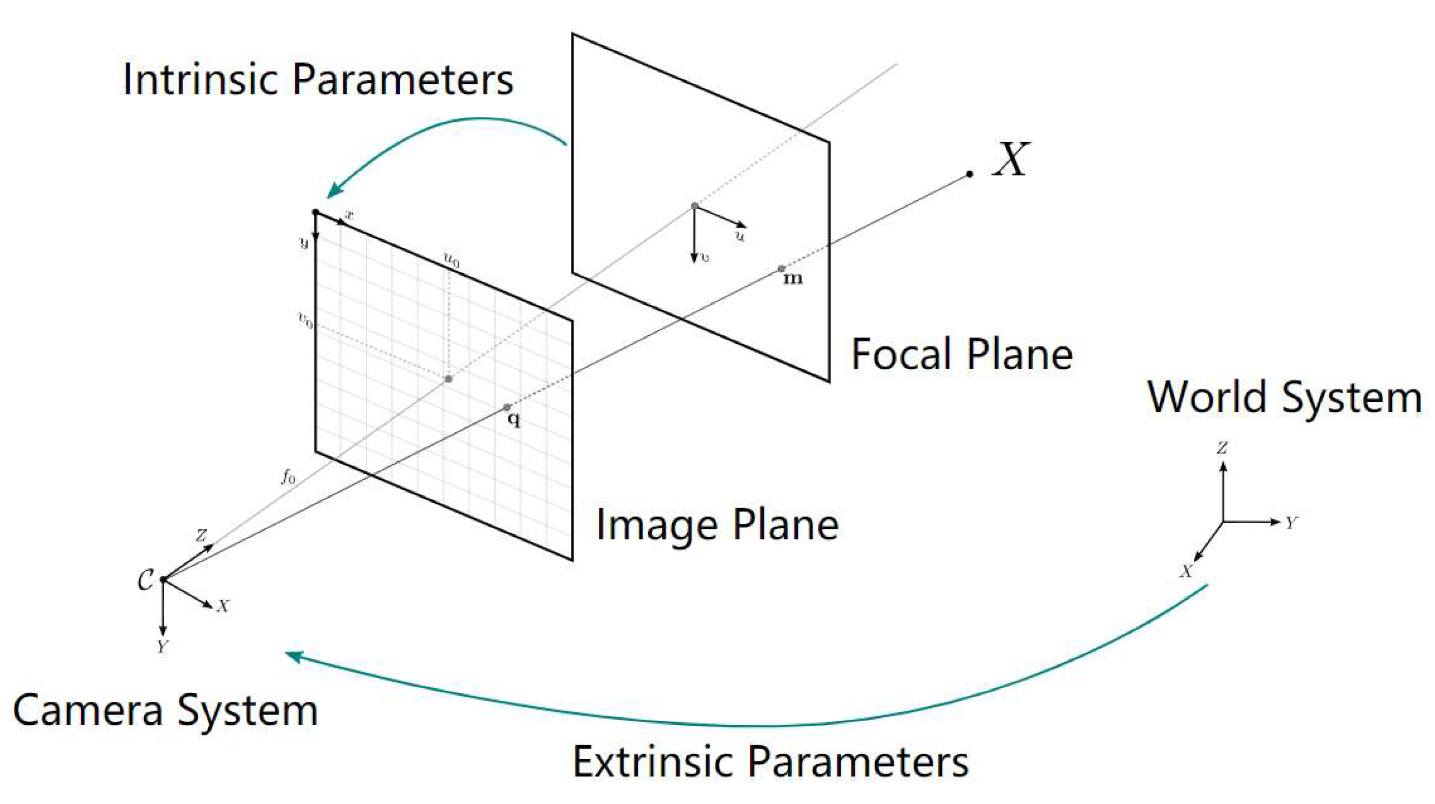
1.2.6. Camera Calibration
Camera calibration is an essential process in computer vision and robotics applications that utilizes images to estimate the three-dimensional geometry of a scene or object. This procedure allows the internal and external parameters of a camera to be determined, including the camera matrix, distortion coefficients, as well as the position and orientation of the camera in space [
26,
27]. Cameras commonly introduce significant distortions in the generated images. The two main types of distortion are radial distortion and tangential distortion. Radial distortion causes straight lines to appear curved and is greater the farther the pixels are from the image center. Similarly, tangential distortion occurs because the lens capturing the image is not perfectly aligned parallel to the image plane. As a result, some areas of the image may appear closer than expected [
28]. These distortions can be represented by the following equations:
The internal parameters (or intrinsic parameters) describe the optical and geometric properties of the camera, such as the focal length (
f), principal point (
u0,
v0), and the (
skew) coefficient (
s), which will always be zero if the image axes are perpendicular. These parameters form the camera calibration matrix
K, which is represented as follows:
Here,
fx and
fy are the focal lengths in the
x and
y axes, respectively. The matrix
K is used to relate coordinates in the three-dimensional space to pixel coordinates in the captured images [
26]. The external parameters (or extrinsic parameters) describe the position and orientation of the camera in the three-dimensional space relative to a coordinate system of the environment. These parameters are represented by a rotation matrix
R and a translation vector
t. The combination of
R and
t forms the extrinsic transformation matrix [
R|t], which is used to convert world coordinates into camera coordinates.
In
Figure 5 [
29], the pinhole camera model (also known as the pinhole camera) is shown. It is a simplified model that illustrates how a camera captures images of the real world by projecting points from a three-dimensional space onto a two-dimensional plane (the image plane).
There are several camera calibration methods, which can be classified into two main categories: pattern-based calibration and non-pattern-based calibration. Pattern-based calibration uses a known calibration object, such as a chessboard or a pattern of circles. The positions of the corners or centers of the circles in the image are used to calculate the matrix K and the radial and tangential distortion coefficients (
k1,
k2,
p1,
p2,
k3) using optimization algorithms such as the nonlinear least squares algorithm [
28].
1.3. Meshroom 3D Reconstruction Software
Meshroom is based on the AliceVision project, a collaboration between several institutions and research companies in the field of computer vision [
29,
30]. The program employs a node-based workflow approach, allowing users to easily customize and adjust the processing stages [
31] with parallel processing, and supports GPU enabling faster performance on compatible hardware [
32]. The Meshroom software has applications in various industries, such as archaeology and cultural heritage, documenting and preserving historical sites and artifacts [
33], surveying and mapping, design and architecture, and entertainment and media. It enables the visualization of architectural and design projects in a three-dimensional environment and the creation of realistic 3D models for films, animations, and video games.
It also has some drawbacks. On the one hand, it can be resource-intensive, especially when processing large datasets, which could result in longer processing times for users with less powerful hardware. On the other hand, some users may find that the software has a moderate learning curve due to its node-based approach and the variety of customization options available [
34].
1.4. Computer Vision and 3D Reconstruction Libraries
Computer vision and 3D reconstruction libraries are essential in the development of applications and research projects in these areas. These libraries provide algorithms, functions, and utilities that facilitate the implementation of image processing, analysis, and 3D modeling solutions. In this section, two key libraries used in this research are presented: OpenCV and Open3D. Both libraries were selected for their versatility, performance, and wide adoption in the research and developer community.
1.4.1. OpenCV
OpenCV (Open-Source Computer Vision) [
35] is an open-source library initially developed by Intel in 1999 and subsequently maintained by an active community of developers. Written primarily in C++ with interfaces available in Python, Java, and other languages, OpenCV provides a wide range of efficient tools and algorithms for image and video analysis and processing in various fields and industries [
36]. The key features of OpenCV include image processing and analysis, video processing, the integration of machine learning algorithms and neural networks for object classification and recognition, and calibration and 3D reconstruction [
37]. These capabilities mean that OpenCV has applications in areas such as surveillance and security, robotics and autonomous vehicles, medicine and biology, industry, manufacturing, entertainment, and augmented reality [
38,
39]. OpenCV has numerous advantages: a high performance compared to other popular image manipulation libraries, open-source, free to use, a wide range of functions, compatibility with multiple platforms and programming languages, and the support of an active community of developers and users [
35]. However, it also presents challenges such as a steep learning curve for beginners and potential performance issues when working with high-resolution or real-time images and videos [
40,
41,
42].
1.4.2. Open3D
Open3D is an open-source library developed by Qianyi Zhou and Jaesik Park in 2018, designed to provide a unified platform for the processing, analysis, and visualization of 3D data [
43,
44]. Written in C++ with interfaces in Python and C++, Open3D includes a wide range of algorithms and tools for handling point clouds, polygonal meshes, and other 3D data in various fields and industries [
45]. The key features of Open3D include point cloud and polygonal mesh processing and analysis, interactive 3D visualization, integration of images and depth, and incorporation of machine learning algorithms and computer vision for classification and segmentation of 3D data [
43]. These capabilities mean that Open3D has applications in areas such as robotics and autonomous vehicles, medicine and biology, archaeology and cultural heritage, topography, cartography, and design and manufacturing [
46,
47,
48,
49]. The main advantages of using Open3D are its ease of use due to the Python and C++ interfaces, being open-source, and the wide range of functions it offers for handling 3D data [
43]. However, it also presents challenges, such as a moderate learning curve for users inexperienced in 3D data processing and analysis and potential compatibility issues when working with specific hardware or software [
50,
51].
1.5. AI-Based Models for 3D Reconstruction
The field of artificial intelligence has experienced rapid advancements in recent years, leading to a series of innovative models and techniques that have shown great potential to improve efficiency and accuracy in photogrammetry and 3D reconstruction. This section presents two AI-based models used in this research: CDS-MVSNet and DROID-SLAM. These models were selected due to their ability to address specific problems in the study domain and their compatibility with the computer vision libraries, OpenCV and Open3D, mentioned earlier.
1.5.1. CDS-MVSNet
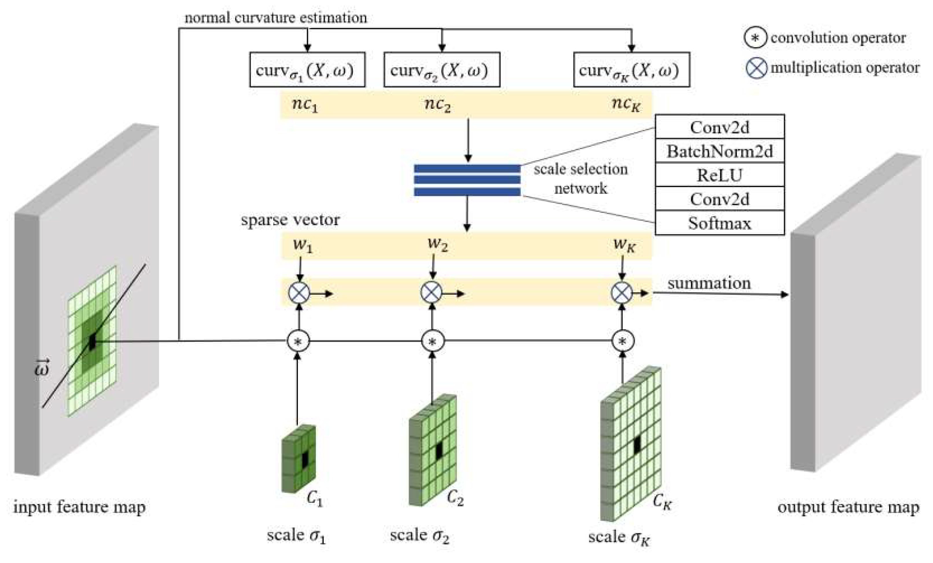
CDS-MVSNet, presented at ICLR 2022, is a novel multi-view stereo (MVS) framework that is used to estimate dense correspondences in high-resolution images with reduced computation and memory consumption [
52]. It consists of a scale-aware feature extraction network with multiple convolutional layers called Curvature-guided Dynamic Scale Convolution (CDSConv; shown in
Figure 6 [
52]), and an MVS depth estimation pipeline. The cascaded approach reduces computational complexity by estimating depths through multiple stages and formulating 3D cost volumes with an appropriate scale for each pixel. Visibility-based cost aggregation enhances stereo-matching performance, utilizing pixel-level visibility information estimated from the curvature. For each stage, this approach formulates a 3D cost volume based on output features, which reduces correspondence ambiguity by utilizing the appropriate scale for each pixel. Additionally, a visibility-based cost aggregation is applied to enhance stereo matching performance. Pixel-level visibility information is estimated from the curvature, implicitly encoding the matching capability of the extracted features. CDS-MVSNet demonstrates a superior performance compared to state-of-the-art methods in various multi-view stereo datasets.
CDS-MVSNet can produce accurate depth maps with high resolution and low noise, handle a wide range of input images (with different resolutions, lighting conditions, and object sizes) and operate in real time on a standard computer. However, it requires a large dataset of multi-view images for training and is sensitive to occlusions. It should be noted that this requires a SLAM system for the localization and mapping phase. The researchers who developed this framework used DROID-SLAM in their proof of concept, but this can be easily configured for the use of other SLAM systems.
1.5.2. DROID-SLAM
DROID-SLAM, proposed in 2021 by Zachary Teed and Jia Deng, researchers from Princeton University [
53,
54], is a deep-learning-based Simultaneous Localization and Mapping (SLAM) system. Its objective is to build an accurate map of the environment and localize the camera’s position in that environment using monocular, stereo, or RGB-D camera images. This approach was first presented at the NeurIPS 2021 conference [
55] and demonstrates superior performance compared to existing SLAM systems, both classical and machine-learning-based.
The architecture called “Differentiable Recurrent Optimization-Inspired Design” (DROID), combines the strengths of classical approaches and deep recurrent networks. This architecture is end-to-end differentiable, allowing the entire system to be learned from input images. It uses recurrent iterative updates based on RAFT (Recurrent All-Pairs Field Transforms) for optical flow. Unlike RAFT, which iteratively updates optical flow, DROID-SLAM iteratively updates camera poses and pixel-wise depth. This update is performed using a Dense Bundle Adjustment (DBA) layer, which computes a Gauss–Newton update for camera poses and pixel-wise depth, thereby improving performance in optical flow estimation.
The DBA layer leverages geometric constraints to enhance the system’s accuracy and robustness, enabling the system to handle stereo or RGB-D inputs without the need for retraining. DROID-SLAM was trained on the TartanAir dataset and demonstrated state-of-the-art performance at various benchmarks. Despite its advantages, such as the ability to handle a wide range of input conditions and computational efficiency, DROID-SLAM has the disadvantage of being sensitive to occlusions.
2. Related Research
Three recent research studies that address 3D reconstruction using drones from different perspectives were analyzed. The first research study utilized LiDAR sensors in combination with drones, the second explored virtual reality techniques applied to the process, and the third focused on using a simulator to carry out the reconstruction.
2.1. Near-Real-Time 3D Reconstruction Using Drones and LiDAR Sensors
In the context of 3D reconstruction, LiDAR sensors have emerged as a valuable tool for assisting drones during image acquisition and metric measurements. However, significant challenges still exist in terms of the accuracy, autonomy, and processing speed of the information captured by drones. In response to these challenges, F. Ahmad et al. developed ARES [
55], a system for near-real-time 3D reconstruction using drones equipped with LiDAR sensors. ARES is a system that addresses the challenges associated with 3D reconstruction, such as optimizing the drone’s battery usage, minimizing positioning errors, and the efficient transmission and processing of the captured data. The system consists of various algorithms and novel techniques that enable the accurate and near-real-time reconstruction of buildings and structures, even after compressing LiDAR sensor data to fit radio-frequency transmission speeds. ARES represents a significant advancement in the field of 3D reconstruction using drones. By addressing bandwidth limitations, SLAM positioning errors, and computational constraints on the drone, ARES provides an innovative approach to acquiring and processing 3D data in various applications. However, it should be noted that this system requires the incorporation of LiDAR sensors on the drones, which incurs a considerable cost.
2.2. Assisted by Virtual Reality
The article “Virtual Reality Aided High-Quality 3D Reconstruction by Remote Drones” [
56,
57] addresses a novel approach to 3D reconstruction using drones. The traditional method involves image collection and subsequent processing, but this new approach employs a telepresence drone system with an onboard processing module and wireless data transmission. The system draws inspiration from deep learning methods and utilizes virtual reality techniques to assist in 3D reconstruction. The system is designed to perform the real-time dense reconstruction of cities. It tackles two problems: the uncertainty of whether all parts of the object have been covered and the lengthy post-processing time. Two technical contributions are proposed to address these problems. The first is a control mechanism based on an inertial visual odometry estimator that provides an immersive viewing experience to the user. The second contribution is an adaptive origin update mechanism that adjusts the drone’s coordinate system origin to its current position as it moves. These two contributions help improve the quality of the 3D model and system performance. Experiments in the simulation system and the real prototype demonstrate the effectiveness of these contributions.
2.3. Monocular Reconstruction Using Drones
In the article, “Monocular 3D Reconstruction of Objects with Camera Mounted on a Drone” [
58], an approach for obtaining point clouds using ORBSLAM2 and the ROS (Robot Operating System) is presented. The article also discusses the processing and 3D reconstruction of captured objects. A ROS node was developed to publish real-time images from a phone camera using the Real-Time Streaming Protocol (RTSP) over the local network. The source code of ORBSLAM2 was slightly modified to adapt it to the researchers’ operating system and to add functionalities such as changing the presentation colors and saving point clouds at the end of execution. The results show point clouds close to the real object description, although many points were found to be outliers, which caused deformations in the 3D reconstructions. To address this issue, the Open3D library was used to remove spurious points using the “remove statistical outlier” method, which employs statistical techniques. After applying the point cloud filter, cleaner point clouds were obtained, and 3D reconstructions were performed using two different methods (Powercrust and Screened Poisson). The reconstructions were more uniform and closer to the original objects.
3. Materials and Methods
3.1. Drone and Workstation
The drone used to perform the experiments is a Tello Romaster TT, a small quadcopter drone developed by DJI for educational purposes (see
Figure 7). It is open-source and offers software scalability through its software development kit and hardware scalability through its sensor adapter with I2C, SPI, UART, and GPIO interfaces. The main components of the drone are a 5 MP HD camera that allows it to capture still images and videos, some different sensors, such as time of flight, a barometer, and an inertial measurement unit or IMU. It also has brushless motors, and a lithium-ion battery allowing it to fly for up to 10 min on a single charge.
The specifications of the computer equipment used to carry out the development of the proof of concept are shown in
Table 1.
3.2. Methodology and Hypotheses
The methodology of the research consisted of conducting a comprehensive review of the specialized literature to identify the parameters and characteristics necessary to obtain a high-quality point cloud and 3D mesh. Additionally, the necessary technical specifications for the design of the vision and navigation subsystems were established, and the most relevant alternatives in terms of computer vision algorithms embedded in drones were identified. Three subsystems (navigation, vision, and 3D mesh reconstruction and export) were developed, which together constituted a prototype for the proof of concept of this research.
Furthermore, the chosen project management methodology for carrying out this work was an incremental methodology, which proved suitable as the developed system consisted of several dependent subsystems that needed to be integrated coherently to achieve the final objective. The incremental methodology is a software development strategy based on constructing a product in small functional parts, called increments, which are progressively integrated to complete the final product. Each increment is a subset of the complete system that can be tested and validated independently, allowing for the identification and correction of errors in an early stage of the development process. This methodology facilitated the establishment of checkpoints and reviews for each subsystem, which aided in the early detection and resolution of inconsistencies.
Moreover, the incremental methodology allows for working iteratively and evolutionarily, meaning that continuous improvements can be made to the different subsystems as they are integrated into the complete system. This is particularly important in research projects, where objectives and requirements can change as more knowledge is acquired.
Therefore, the use of this methodology is justified as it is suitable for the development of complex and dependent systems, such as the one proposed in this research. It enables the early validation of each subsystem, identification and correction of errors, and continuous improvements as research progress is made.
3.3. Rationale
The theoretical basis of this work is grounded in the research and application of SLAM (Simultaneous Localization and Mapping) algorithms and 3D reconstruction that generate accurate and detailed three-dimensional models of objects or environments from images captured by a drone. These algorithms allow for the real-time estimation of the camera’s position and orientation, while obtaining a three-dimensional representation of the environment. The main methods and concepts on which the work is based include remote drone control, drone camera calibration (described in
Section 1.2.6), the application of SLAM (described in
Section 1.2.5) to estimate the drone’s trajectory, and 3D reconstruction using MVS (described in
Section 1.2.4).
3.4. Tools and Algorithms
For the implementation of the proof of concept, the following tools and algorithms, which are described in
Section 1, were used: OpenCV, CDSFNet, DROID-SLAM, Meshroom, and Open3D. In addition, the Poisson Surface Reconstruction (PSR) algorithm was used for the export of 3D meshes, the Flask framework for creating a web interface to control the drone, and FFmpeg [
59,
60] for decoding the video signal emitted by the drone.
3.5. Design and Development of the Proof of Concept
The proof of concept was designed to evaluate the feasibility and effectiveness of a real-time 3D model generation system using a drone. To achieve this, the vision, navigation, and 3D mesh export subsystems were developed and integrated. Each of these components and their respective implementations are detailed below.
3.5.1. Vision Subsystem
The vision subsystem, implemented in Python, is responsible for receiving and processing the video stream transmitted by the drone. A UDP connection is established with the drone, and the received images are decoded using the FFmpeg library for subsequent processing with the OpenCV library. Initially, the challenge of decoding the video stream transmitted over the UDP protocol was addressed. However, the decoding process proved to be inefficient and slow, resulting in difficulties in real-time content visualization. To address this problem, an asynchronous approach was implemented, and adjustments were made to the FFmpeg parameters to optimize and accelerate the hardware decoding of the video. By properly configuring these options, a significant improvement in decoding speed was achieved, enabling smooth and real-time video playback.
3.5.2. Navigation Subsystem
The navigation subsystem was also developed in Python to establish bidirectional communication with the drone and is based on the Tello SDK. Communication is carried out using the UDP protocol, allowing commands to be sent to the drone (takeoff, land, move in different directions, rotate, etc.) and confirmations to be received from the drone. An event handler was implemented to handle the drone’s responses and ensure proper synchronization between the commands sent and the actions performed.
3.5.3. 3D Mesh Reconstruction and Export Subsystem
This subsystem incorporates the DROID-SLAM algorithm to estimate the drone’s position and orientation in space over time. As the drone moves, a real-time map of the environment is generated, which serves as input to the CDS-MVSNet framework. To enable real-time 3D reconstruction, a buffer was implemented to store the captured images and supply them to the algorithm as needed.
An essential aspect of accurately performing 3D mesh reconstruction and export is to properly calibrate the drone’s camera to obtain intrinsic parameters. This calibration process was carried out using the Meshroom software and a chessboard pattern with dimensions of 5 × 7. Camera calibration was crucial to obtain precise information regarding position, orientation, and lens distortion, which are essential to ensuring the accuracy of 3D reconstruction.
The term “real-time” refers to the processing and reconstruction of the video input simultaneously with data capture, allowing for the almost instant visualization of the 3D reconstruction. However, it is important to note that, with the graphics card used in this study, there is minimal delay during the reconstruction process. However, this delay can be eliminated by using more advanced and suitable hardware.
Once the 3D reconstruction was complete, a point cloud was obtained, which can be exported by pressing the “X” key. It can also be converted into a three-dimensional mesh using the Poisson Surface Reconstruction algorithm by pressing the “M” key. The choice of this algorithm is based on its ability to generate high-quality meshes in a short period of time from sparse and noisy point clouds, provided that its parameters are properly adjusted.
Figure 8 shows a screenshot of the 3D reconstruction subsystem during the reconstruction process, illustrating three windows reflecting different aspects of the real-time process. The window on the right displays the frame corresponding to the video stream being processed at that moment, providing a view of the images captured by the drone. The second window presents the 3D viewer of Open3D, in which the real-time 3D reconstruction and estimation of the drone’s camera trajectory can be observed. This viewer offers the ability to interact with the 3D object, allowing manipulation through actions such as rotation and scaling while reconstruction is ongoing. The third window displays a terminal running the nvtop program, which monitors the GPU’s status. In the screenshot, the GPU is operating at nearly its maximum capacity, demonstrating the high resource demand required to perform real-time 3D reconstruction.
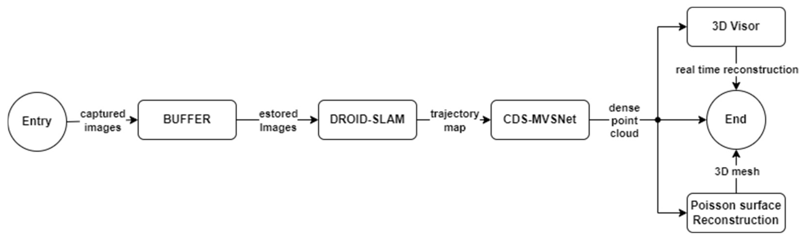
Figure 9 presents a flowchart illustrating the process of capturing and processing images obtained by a drone equipped with a calibrated camera. These images are temporarily stored in a buffer and subsequently processed using the DROID-SLAM model. Through this model, a trajectory map is generated, which serves as an input to the CDS-MVSNet module. This module provides the input information to the 3D viewer implemented with the Open3D library, allowing for the visualization of the real-time 3D reconstruction. Additionally, the system offers the option to export the dense point cloud as a PLY format object or generate and export a 3D mesh using the Poisson Surface Reconstruction algorithm.
3.5.4. Web Application and Complete System
To facilitate interaction between the user and the system, a web application was implemented using the Flask framework. This application allows the user to control the drone, view its video stream, and visualize the real-time reconstruction. The interface was developed with reference to the course “Drone Programming with Python-Face Recognition & Tracking” [
61] by Jun Sakai. It also includes an integrated 3D viewer, using Open3D to display the reconstruction results and enable manipulation of the generated model.
Figure 10 represents the system design in a block diagram consisting of four main blocks. In the center is the “Web Application” block, which acts as the central core and communication point between the other subsystems. Surrounding this central block are the “Reconstruction Subsystem”, “Navigation Subsystem”, and “Vision Subsystem” blocks. Each of these blocks bidirectionally communicates exclusively with the “Web Application” block, establishing a relationship of interdependence among them.
The block diagram illustrates the modular structure of the system, emphasizing the importance of the web application as a coordination and control element. It also shows how the subsystems work together to perform the functions of vision, navigation, and reconstruction, while the web application facilitates user interaction and result visualization.
Figure 11a shows a screenshot of the web application interface as viewed from a smartphone.
As seen in
Figure 11a, the interface allows us to control the drone and view its video stream. Additionally, it enables the initiation of the 3D reconstruction.
Figure 12b illustrates the general interaction scheme with the system, showing the interaction between the user, the server, and the drone. The user utilizes a smartphone to control the drone and manage the 3D reconstruction through a web interface provided by the server. The smartphone connects to the router, which, in turn, communicates with the server hosting the 3D processing and reconstruction system. This server establishes a connection with the drone through the Wi-Fi access point generated by the drone itself. The drone sends the real-time video stream to the server, where the processing and 3D reconstruction take place. In this way, the user can control the drone, initiate, or stop the 3D reconstruction, and view the video stream emitted by the drone.
To facilitate the compilation, installation, and configuration of the prototype presented in this study, a Docker image, containing the complete system and ready to use, is generated, allowing other researchers to more easily replicate the obtained results. The reference to this image is available in the official repository of the system’s source code. It is important to note that, to replicate the results, interested researchers must use a drone compatible with the TELLO SDK 2.0. Additionally, the proper calibration of the drone’s camera before proceeding with the generation of a 3D reconstruction is essential to ensure acceptable results.
It should be mentioned that Docker containers are primarily designed to run command-line-based applications and background services. Therefore, to visualize the 3D reconstruction, it was necessary to install and configure an X server within the container, which allows the application inside the container to display its graphical interface without depending on the host system’s X server. The image is also configured to access and control the system via VNC (port 5900) or noVNC (port 6080). Additionally, the web interface is accessible through port 5001.
4. Results
It is necessary to evaluate whether the specific set objectives have been satisfactorily achieved, so that the general objective of the work is validated (see
Section 1. Introduction). In this way, if the specific objectives of the work have been successfully achieved, it can be stated that the general objective has been fulfilled. The validation methods used for the evaluation of the specific objectives are listed below:
Validation of specific objective 1: Determine the requirements for the automatic reconstruction of 3D point clouds and meshes using images. To validate this objective, a comparison will be made between the identified technical specifications and the existing solutions and approaches in the field of 3D reconstruction using images. The characteristics of a high-quality point cloud and 3D mesh will be identified, and proof-of-concept tests will be conducted to determine the feasibility and effectiveness of the selected techniques and algorithms. The results of these tests will be evaluated using the corresponding metrics for the identified characteristics: accuracy, density, completeness, and texture.
Validation of specific objective 2: Design and develop the vision subsystem. To validate the design and development of the vision subsystem, field and laboratory tests will be conducted, including image capture and processing under different environmental and lighting conditions. Additionally, the quality of the obtained images will be evaluated by comparing them with reference images and measuring metrics such as sharpness, contrast, and distortion.
Validation of specific objective 3: Design and develop the navigation subsystem. The validation of the navigation subsystem will be carried out through flight tests in different environments and conditions. The latency, stability, and responsiveness of the navigation system will be evaluated, as well as its ability to maintain a predetermined trajectory and adapt to changes in the environment.
Validation of specific objective 4: Design and develop the subsystem for exporting 3D meshes based on the captured images obtained by the navigation system and powered by the vision system. The validation of the 3D reconstruction and mesh export subsystem will be carried out by comparing the generated 3D models with the reference models obtained using conventional techniques. Additionally, the efficiency of the export process will be evaluated in terms of processing time and the required computational resources.
4.1. Density, Accuracy, Completeness and Texture
To determine the requirements for the automatic reconstruction of 3D point clouds and meshes using images, we started by identifying the characteristics that are typical of a dense point cloud and a high-quality 3D mesh. These characteristics are:
Density: Refers to the number of points per unit area. A higher density implies higher resolution and detail of the represented surface. Density depends on the distance and angle of image capture, as well as the software and parameters used to generate the point cloud [
62].
Accuracy: Refers to the degree of correspondence between the points and the real surface. A higher accuracy implies less distortion or error in the representation. Accuracy depends on the quality and calibration of the camera or sensor, as well as the software and algorithms used to align and process the images [
63].
Completeness: Refers to the degree of coverage of the represented surface. Higher completeness implies less presence of gaps or areas without information. Completeness depends on the number and distribution of captured images, as well as the software and methods used to fill or interpolate the gaps [
64,
65].
Texture: Refers to the visual appearance of the represented surface. A higher texture implies greater fidelity in the color and brightness of the surface. Texture depends on the lighting and environmental conditions during image capture, as well as the software and processes used to generate and apply the texture to the 3D mesh [
63].
After conducting an exhaustive analysis of numerous algorithms, models, and approaches available in state-of-the-art methods regarding 3D reconstruction, the DROID-SLAM (see
Section 1.5.2) and CDS-MVSNet (see
Section 1.5.1) models were identified as preexisting solutions that, when combined, and by leveraging their synergies, can offer high levels of density, accuracy, completeness, and texture.
To evaluate the effectiveness of integrating these systems based on the mentioned metrics, a comparison was conducted between the results obtained using the proposed system and a reference textured mesh generated using Meshroom software (see
Section 1.3).
Figure 12a shows the object used for this test. It is a small replica of the Eiffel Tower measuring 16 cm × 16 cm × 40 cm. This Eiffel Tower scale model was used for testing due to the limitations of the aircraft used in the project. The DJI Tello Robomaster TT is for indoor use and very vulnerable to wind; therefore, it has very little capacity for outdoor flight.
Figure 12b illustrates the results obtained through the proposed system, while
Figure 13a shows the results obtained using Meshroom software. As can be seen, the accuracy of both reconstructions is of a high quality. However, the reconstruction performed using Meshroom more closely resembles reality, indicating a higher accuracy. Regarding the density of the models, 1,626,207 points were recorded in the point cloud generated by the proposed system, and 2,125,395 points were recorded in the point cloud generated by Meshroom, demonstrating that the density obtained using Meshroom is higher. In terms of completeness, both models exhibit similar characteristics as both cases fully close the surface of the represented object. However, it is important to note that it was necessary to repeat the experiment multiple times with new shots, changing the configuration and applying masks to highlight the object because the resulting representation with Meshroom did not correctly reconstruct the top part of the tower (see
Figure 13b). This demonstrates that conventional algorithms (computationally expensive) can sometimes be less effective. Finally, the texture of both models is true to reality, preserving the color and brightness of the objects, although it can be observed that the texture of the representation obtained using conventional methods is more detailed. On the other hand, it is observed that the representations obtained using the proposed system lose texture in their transition from a dense point cloud to polygonal mesh.
Table 2 shows the comparison of these results. It can be concluded that, although the combination of DROID-SLAM and CDS-MVSNet offers promising results in terms of density, accuracy, completeness, and texture, the comparative analysis reveals that Meshroom software exhibits higher accuracy and density in 3D reconstruction. However, it should be noted that the completeness and texture of both models are similar and correspond to reality. These results suggest that, although the proposed integration of DROID-SLAM and CDS-MVSNet is valid and effective, there is still room for improvement to achieve optimal levels of accuracy and density compared to solutions that employ conventional algorithms.
4.2. 3D Mesh Exportation
Next, we present the results corresponding to the fourth specific objective of the research. This study aims to compare the complete process of generating and exporting a 3D mesh using the 3D reconstruction and mesh export subsystem (see
Figure 14a). The 3D mesh was obtained via the reference software, Meshroom (see
Figure 14b).
In this comparison, the variables to be measured were the processing time required for the 3D reconstruction and mesh export and the minimum hardware resources needed to carry out the experiment. For this, a circular flight of one minute and three seconds was executed at a speed of 30 frames per second (FPS) using a RoboMaster TT drone around a small figure of the Virgin of Medjugorje with dimensions of 35 cm × 20 cm × 68 cm, while real-time reconstruction was performed using the proposed system. Subsequently, a 3D reconstruction was performed using the frames extracted from the video using the equipment described in
Table 1 of
Section 3.1.
Table 3 shows a comparison between the processing method using Meshroom and the proposed system in terms of processing time and hardware resources required. In terms of processing time, Meshroom took 136 min and 12 s to complete the 3D reconstruction, while the proposed system finished the process in just 1 min and 13 s. It is important to mention that the proposed system requires a few additional seconds for preheating and buffer filling before starting the reconstruction process. Despite this, the processing time of the proposed system is significantly shorter compared to that of the Meshroom software, which represents an improvement in terms of efficiency.
Regarding hardware resources, both methods require 8 GB of RAM. However, Meshroom requires an NVIDIA CUDA-enabled GPU with a capacity greater than or equal to 2.0 and 8 GB of RAM [
66], while the proposed system demands an NVIDIA CUDA-enabled GPU with a capacity greater than or equal to 3.0 and 16 GB of RAM. Although the proposed system requires higher hardware resources, these are compensated for by the notable reduction in processing time compared to Meshroom.
5. Conclusions
A navigation and 3D reconstruction system based on advanced computer vision algorithms and a drone equipped with a monocular camera was proposed and developed. The main objective of this work was to create a system capable of capturing and processing visual information of objects and environments, generating accurate and efficient 3D models in terms of processing time (in real-time).
Some examples of 3D captures taken outdoors are shown in
Figure A1,
Figure A2,
Figure A3 and
Figure A4 in
Appendix A. The results seem to be quite conditioned to the (very low) resolution and the capabilities of the DJI Tello Robomaster TT camera, as can be seen in the frames in
Figure A1a,
Figure A2a and
Figure A3a. Moreover, they improve in good lighting conditions, as in the case of
Figure A2. On the other hand, they become worse in windy conditions, as can be seen in
Figure A3. In
Figure A4, a depiction of a motorcycle is presented. Furthermore, the illustration portrays the pilot of the aircraft executing an enveloping flight maneuver around the motorcycle.
The 3D reconstruction and mesh export subsystems were compared with existing reference applications and software in the market (Meshroom software). It has been verified that the proposed system offers a significant improvement in terms of efficiency by reducing the processing time compared to the Meshroom software. Despite requiring more hardware resources and obtaining slightly less dense and precise models, the proposed system compensates for these differences with a significant reduction in the time required to generate the 3D reconstruction, along with a higher likelihood of achieving completeness on the first attempt.
Based on the obtained results, it can be affirmed that the research hypothesis is valid, and the proposed system is demonstrated to be a viable and efficient solution compared to the reference alternatives. The effectiveness of the system supports its applicability in real-world scenarios (such as infrastructure inspection and maintenance, archaeology, cartography, and 3D modeling of indoor and outdoor spaces), thereby considering its implementation in future research and developments in the field of robotics and computer vision.
Author Contributions
Conceptualization, J.S.-S. and S.B.R.; methodology, J.S.-S. and J.C.B.; software, J.C.B.; validation J.S.-S., J.C.B. and S.B.R.; formal analysis, J.S.-S. and J.C.B.; investigation, J.S.-S., J.C.B. and S.B.R.; resources, J.S.-S. and S.B.R.; data curation, J.C.B.; writing—original draft preparation, J.C.B., J.S.-S. and S.B.R.; writing—review and editing, J.S.-S. and S.B.R.; visualization, J.C.B.; supervision, J.S.-S.; project administration, J.S.-S.; funding acquisition, J.S.-S. All authors have read and agreed to the published version of the manuscript.
Funding
This research and the APC was funded by Universidad Francisco de Vitoria, grant numbers UFV2022-45 “Automatic creation of 3D meshes of objects, buildings, and scenery using drones” and UFV2023-27 “Automatic creation of closed and complete 3D meshes using drones”.
Data Availability Statement
Acknowledgments
The authors would like to thank the Universidad Francisco de Vitoria and the Universidad Europea de Madrid for their support.
Conflicts of Interest
The authors declare no conflict of interest.
Appendix A
This appendix contains four examples of outdoor reconstruction, three different building sizes and lighting and wind conditions, and the reconstruction of a motorbike.
Figure A1.
Three-dimensional mesh reconstruction of truck scale captured under very low light conditions. (a) Frame from the video captured by the drone. (b) Three-dimensional model with texture. (c) Three-dimensional mesh with triangles.
Figure A1.
Three-dimensional mesh reconstruction of truck scale captured under very low light conditions. (a) Frame from the video captured by the drone. (b) Three-dimensional model with texture. (c) Three-dimensional mesh with triangles.
Figure A2.
Three-dimensional mesh reconstruction of farmhouse captured under good light conditions. (a) Frame from the video captured by the drone. (b) Three-dimensional model with texture. (c) Three-dimensional mesh with triangles.
Figure A2.
Three-dimensional mesh reconstruction of farmhouse captured under good light conditions. (a) Frame from the video captured by the drone. (b) Three-dimensional model with texture. (c) Three-dimensional mesh with triangles.
Figure A3.
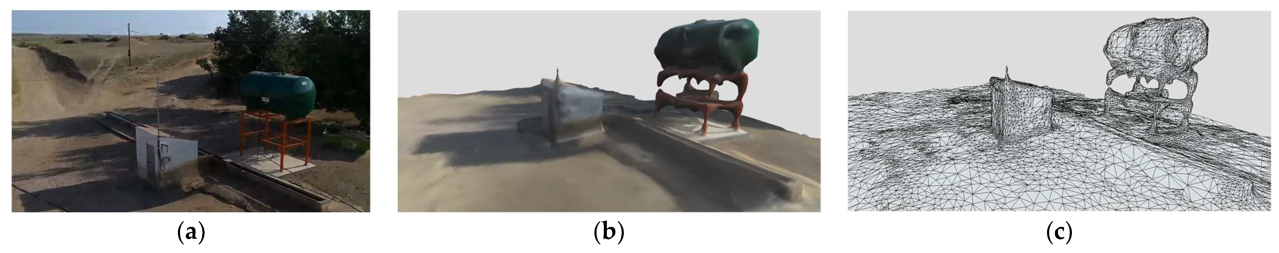
Three-dimensional mesh reconstruction shed, water tank, and watering trough for livestock captured under very bad (wind) flight conditions. It can be observed that the supporting structure of the water tank is not accurately reconstructed. (a) Frame from the video captured by the drone. (b) Three-dimensional model with texture. (c) Three-dimensional mesh with triangles.
Figure A3.
Three-dimensional mesh reconstruction shed, water tank, and watering trough for livestock captured under very bad (wind) flight conditions. It can be observed that the supporting structure of the water tank is not accurately reconstructed. (a) Frame from the video captured by the drone. (b) Three-dimensional model with texture. (c) Three-dimensional mesh with triangles.
Figure A4.
Three-dimensional mesh reconstruction of motorcycle. (a) Image of the pilot and the aircraft from the video captured by the drone executing an enveloping flight maneuver around the motorcycle. (b) Three-dimensional model with texture. (c) Three-dimensional mesh with triangles.
Figure A4.
Three-dimensional mesh reconstruction of motorcycle. (a) Image of the pilot and the aircraft from the video captured by the drone executing an enveloping flight maneuver around the motorcycle. (b) Three-dimensional model with texture. (c) Three-dimensional mesh with triangles.
References
- Alamouri, A.; Lampert, A.; Gerke, M. Impact of Drone Regulations on Drone Use in Geospatial Applications and Research: Focus on Visual Range Conditions, Geofencing and Privacy Considerations. PFG 2023. [Google Scholar] [CrossRef]
- Specht, M.; Widźgowski, S.; Stateczny, A.; Specht, C.; Lewicka, O. Comparative Analysis of Un-manned Aerial Vehicles Used in Photogrammetric Surveys. Int. J. Mar. Navig. Saf. Sea Transp. 2023, 17, 2. [Google Scholar] [CrossRef]
- Rogers, J. The Second Drone Age: Defining war in the 2020s. Def. Secur. Anal. 2023, 39, 256–259. [Google Scholar] [CrossRef]
- Ahmed, F.; Mohanta, J.C.; Keshari, A.; Yadav, P.S. Recent Advances in Unmanned Aerial Vehicles: A Review. Arab. J. Sci. Eng. 2022, 47, 7963–7984. [Google Scholar] [CrossRef]
- Liang, H.; Lee, S.C.; Bae, W.; Kim, J.; Seo, S. Towards UAVs in Construction: Advancements, Chal-lenges, and Future Directions for Monitoring and Inspection. Drones 2023, 7, 202. [Google Scholar] [CrossRef]
- Floreano, D.; Wood, R. Science, technology and the future of small autonomous drones. Nature 2015, 521, 460–466. [Google Scholar] [CrossRef] [PubMed]
- Bappy, A.M.; Asfak-Ur-Rafi, M.D.; Islam, M.S.; Sajjad, A.; Imran, K.N. Design and Development of Unmanned Aerial Vehicle (Drone) for CIVIL applications. Doctoral Dissertation, BRAC University, Dhaka, Bangladesh, 2015. [Google Scholar]
- Granshaw, S.I. RPV, UAV, UAS, RPAS … or just drone? Photogramm. Rec. 2018, 33, 160–170. [Google Scholar] [CrossRef]
- Camuffo, E.; Mari, D.; Milani, S. Recent Advancements in Learning Algorithms for Point Clouds: An Updated Overview. Sensors 2022, 22, 1357. [Google Scholar] [CrossRef]
- A survey on deep learning advances on different 3D data representations. Eman Ahmed, Alexandre Saint, Abd El Rahman Shabayek, Kseniya Cherenkova, Rig Das, Gleb Gusev, Djamila Aouada, and Bjorn Ottersten. arXiv 2018, arXiv:1808.01462.
- Štroner, M.; Urban, R.; Seidl, J.; Reindl, T.; Brouček, J. Photogrammetry Using UAV-Mounted GNSS RTK: Georeferencing Strategies without GCPs. Remote Sens. 2021, 13, 1336. [Google Scholar] [CrossRef]
- Deliry, S.I.; Avdan, U. Accuracy of Unmanned Aerial Systems Photogrammetry and Structure from Motion in Surveying and Mapping: A Review. J. Indian. Soc. Remote Sens. 2021, 49, 1997–2017. [Google Scholar] [CrossRef]
- Zhang, L.; Liu, Y.; Sun, Y.; Lan, C.; Ai, H.; Fan, Z. A review of developments in the theory and technology of three-dimensional reconstruction in digital aerial photogrammetry. Acta Geod.-Ca Et Cartogr. Sin. 2022, 51, 1437–1457. [Google Scholar] [CrossRef]
- Manyinsa, D. The Best Photogrammetry Software (Free and Paid). MUO. 2022. Available online: https://www.makeuseof.com/best-photogrammetry-software-free-paid/ (accessed on 1 November 2022).
- Kesack, R. Processing in Progress: A Benchmark Analysis of Photogrammetry Applications for Digital Architectural Documentation. Technol. Archit. + Des. 2022, 6, 118–122. [Google Scholar] [CrossRef]
- Jiménez-Jiménez, S.I.; Ojeda-Bustamante, W.; Marcial-Pablo, M.d.J.; Enciso, J. Digital Terrain Models Gener-ated with Low-Cost UAV Photogrammetry: Methodology and Accuracy. ISPRS Int. J. Geo-Inf. 2021, 10, 285. [Google Scholar] [CrossRef]
- Fraser, B.T.; Bunyon, C.L.; Reny, S.; Lopez, I.S.; Congalton, R.G. Analysis of Unmanned Aerial System (UAS) Sensor Data for Natural Resource Applications: A Review. Geographies 2022, 2, 303–340. [Google Scholar] [CrossRef]
- Wu, B. Photogrammetry for 3D Mapping in Urban Areas. In Urban Informatics; Shi, W., Goodchild, M.F., Batty, M., Kwan, M.-P., Zhang, A., Eds.; Springer: Singapore, 2021; pp. 401–413. [Google Scholar] [CrossRef]
- Furukawa, Y.; Hernández, C. Multi-View Stereo: A Tutorial. Found. Trends® Comput. Graph. Vis. 2015, 9, 1–148. [Google Scholar] [CrossRef] [Green Version]
- Wang, X.; Wang, C.; Liu, B.; Zhou, X.; Zhang, L.; Zheng, J.; Bai, X. Multi-view stereo in the Deep Learning Era: A comprehensive review. Displays 2021, 70, 102102. [Google Scholar] [CrossRef]
- es.mathworks.com. (n.d.). SLAM (localización y Mapeo Simultáneos)—MATLAB y SIMULINK. Available online: https://es.mathworks.com/discovery/slam.html (accessed on 30 October 2022).
- Gupta, A.; Fernando, X. Simultaneous Localization and Mapping (SLAM) and Data Fusion in Unmanned Aerial Vehicles: Recent Advances and Challenges. Drones 2022, 6, 85. [Google Scholar] [CrossRef]
- Taheri, H.; Xia, Z.C. SLAM; definition and evolution. Eng. Appl. Artif. Intell. 2020, 97, 104032. [Google Scholar] [CrossRef]
- Liu, S.; Guo, P.; Feng, L.; Yang, A. Accurate and Robust Monocular SLAM with Omnidirectional Cameras. Sensors 2019, 19, 4494. [Google Scholar] [CrossRef] [PubMed] [Green Version]
- Ullah, I.; Su, X.; Zhang, X.; Choi, D. Simultaneous Localization and Mapping Based on Kal-man Filter and Extended Kalman Filter. Wirel. Commun. Mob. Comput. 2020, 2020, 2138643. [Google Scholar] [CrossRef]
- Luhmann, T.; Fraser, C.; Maas, H.G. Sensor modelling and camera calibration for close-range photogrammetry. ISPRS J. Photogramm. Remote Sens. 2016, 115, 37–46. [Google Scholar] [CrossRef]
- Sonugur, G. A Review of quadrotor UAV: Control and SLAM methodologies ranging from conven-tional to innovative approaches. Robot. Auton. Syst. 2022, 161, 104342. [Google Scholar] [CrossRef]
- Zhi, Z.; Xiang, Z.; Zheng, M.; Lianyi, M. Design and implementation of camera calibration system based on OpenCV. In Proceedings of the 2011 International Conference on Electric Information and Control Engineering, Wuhan, China, 15–17 April 2011; pp. 3110–3113. [Google Scholar] [CrossRef]
- Enesi, I.; Kuqi, A. Analyzing parameters in 3D reconstruction photogrammetry in Meshroom, a case study. In Proceedings of the 2022 11th Mediterranean Conference on Embedded Computing (MECO), Budva, Montenegro, 7–11 June 2022; pp. 1–8. [Google Scholar] [CrossRef]
- alicevision.org. (n.d.). AliceVision|Photogrammetric Computer Vision Framework. Available online: https://alicevision.org/#meshroom (accessed on 20 September 2022).
- Anon. The Step-by-Step Meshroom Tutorial for Beginners. 2020. Available online: https://www.gamedesigning.org/learn/meshroom-tutorial/ (accessed on 14 November 2022).
- Masson, J.E.N.; Petry, M.R. Comparison of Algorithms for 3D Reconstruction. In Proceedings of the 2019 IEEE International Conference on Autonomous Robot Systems and Competitions (ICARSC), Porto, Portugal, 24–26 April 2019; pp. 1–6. [Google Scholar] [CrossRef]
- Cerasoni, J.N.; do Nascimento Rodrigues, F.; Tang, Y.; Hallett, E.Y. Do-It-Yourself digital archaeology: Introduction and practical applications of photography and photogrammetry for the 2D and 3D representation of small objects and artefacts. PLoS ONE 2022, 17, e0267168. [Google Scholar] [CrossRef] [PubMed]
- Mostafa, Y.M.; Al-Berry, M.N.; Shedeed, H.A.; Tolba, M.F. Data Driven 3D Reconstruction from 2D Images: A Review. In Proceedings of the 8th International Conference on Advanced Intelligent Systems and Informatics 2022. AISI 2022. Lecture Notes on Data Engineering and Communications Technologies, Cairo, Egypt, 20–22 November 2022; Hassanien, A.E., Snášel, V., Tang, M., Sung, T.W., Chang, K.C., Eds.; Springer: Cham, Switzerland, 2023; Volume 152. [Google Scholar] [CrossRef]
- OpenCV. About. OpenCV. 2018. Available online: https://opencv.org/about/ (accessed on 15 November 2022).
- Bradski, G. The openCV library. Dr. Dobb’s J. Softw. Tools Prof. Program. 2000, 25, 120–123. [Google Scholar]
- Zelinsky, A. Learning OpenCV---Computer Vision with the OpenCV Library (Bradski, G.R. et al.; 2008) [On the Shelf]. IEEE Robot. Autom. Mag. 2009, 16, 100. [Google Scholar] [CrossRef]
- Agrawal, R. (n.d.). Open CV: Applications & Functions|Analytics Steps. [Online]. Available online: https://www.analyticssteps.com/blogs/open-cv-applications-functions (accessed on 23 October 2022).
- Blubaugh, D.A.; Harbour, S.D.; Sears, B.; Findler, M.J. OpenCV and Perception. In Intelligent Autonomous Drones with Cognitive Deep Learning; Apress: Berkeley, CA, USA, 2022. [Google Scholar] [CrossRef]
- Ajala, S.; Jalajamony, H.M.; Nair, M.; Marimuthu, P.; Fernandez, R.E. Comparing machine learning and deep learning regression frameworks for accurate prediction of dielectrophoretic force. Sci. Rep. 2022, 12, 1197. [Google Scholar] [CrossRef]
- Roynard, M.; Carlinet, E.; Géraud, T. A Modern C++ Point of View of Programming in Image Processing. In Proceedings of the 21st ACM SIGPLAN International Conference on Generative Programming: Concepts and Experiences (GPCE 2022), Auckland, New Zealand, 6–7 December 2022; Association for Computing Machinery: New York, NY, USA, 2022; pp. 164–171. [Google Scholar] [CrossRef]
- Moreira, G.; Magalhães, S.A.; Pinho, T.; dos Santos, F.N.; Cunha, M. Benchmark of Deep Learning and a Proposed HSV Colour Space Models for the Detection and Classification of Greenhouse Tomato. Agronomy 2022, 12, 356. [Google Scholar] [CrossRef]
- www.open3d.org. (n.d.). Open3D: A Modern Library for 3D Data Processing—Open3D 0.10.0 Documentation. Available online: http://www.open3d.org/docs/release/ (accessed on 14 October 2022).
- Zhou, Q.-Y.; Park, J.; Koltun, V. Open3D: A Modern Library for 3D Data Processing. arXiv 2018, arXiv:1801.09847 [cs]. Available online: https://arxiv.org/abs/1801.09847 (accessed on 14 October 2022).
- Jelavic, E.; Nubert, J.; Hutter, M. Open3d slam: Point cloud based mapping and localization for education. In Proceedings of the Robotic Perception and Mapping: Emerging Techniques, ICRA 2022 Workshop, Philadelphia, PA, USA, 23–27 May 2022; ETH Zurich, Robotic Systems Lab: Zürich, Switzerland, 2022; p. 24. [Google Scholar]
- Arshad, B.; Barthelemy, J.; Perez, P. Autonomous Lidar-Based Monitoring of Coastal Lagoon Entrances. Remote Sens. 2021, 13, 1320. [Google Scholar] [CrossRef]
- Raimundo, J.; Lopez-Cuervo Medina, S.; Aguirre de Mata, J.; Prieto, J.F. Multisensor Data Fusion by Means of Voxelization: Application to a Construction Element of Historic Heritage. Remote Sens. 2022, 14, 4172. [Google Scholar] [CrossRef]
- Ferdani, D.; Fanini, B.; Piccioli, M.C.; Carboni, F.; Vigliarolo, P. 3D Reconstruction and Validation of Historical Background for Immersive VR Applications and Games: The Case Study of the Forum of Augustus in Rome. J. Cult. Herit. 2020, 43, 129–143. [Google Scholar] [CrossRef]
- Xu, T.; An, D.; Jia, Y.; Yue, Y. A Review: Point Cloud-Based 3D Human Joints Estimation. Sensors 2021, 21, 1684. [Google Scholar] [CrossRef] [PubMed]
- GitHub (n.d.). Compilation Error on Ubuntu 22 · Issue #6003 · isl-org/Open3D. Available online: https://github.com/isl-org/Open3D/issues/6003 (accessed on 29 October 2022).
- GitHub. (n.d.). Compilation Failing with CUDA Enabled · Issue #5112 · isl-org/Open3D. Available online: https://github.com/isl-org/Open3D/issues/5112 (accessed on 29 October 2022).
- Giang, K.T.; Song, S.; Jo, S. Curvature-Guided Dynamic Scale Networks for Multi-View Stereo. arXiv 2022, arXiv:2112.05999 [cs]. Available online: https://arxiv.org/abs/2112.05999v3 (accessed on 16 October 2022).
- Teed, Z.; Deng, J. Droid-slam: Deep visual slam for monocular, stereo, and rgb-d cameras. Adv. Neural Inf. Process. Syst. 2021, 34, 16558–16569. [Google Scholar]
- Jin, Q.; Liu, Y.; Man, Y.; Li, F. Visual SLAM with RGB-D Cameras. In Proceedings of the 2019 Chinese Control Conference (CCC), Guangzhou, China, 27–30 July 2019; pp. 4072–4077. [Google Scholar] [CrossRef]
- Ahmad, F.; Shin, C.; Chai, E.; Sundaresan, K.; Govindan, R. ARES: Accurate, Autonomous, Near Real-time 3D Reconstruction Using Drones. arXiv 2021, arXiv:2104.08634 [cs, eess]. Available online: https://arxiv.org/abs/2104.08634 (accessed on 5 October 2022).
- Zhang, D.; Xu, F.; Pun, C.-M.; Yang, Y.; Lan, R.; Wang, L.; Li, Y.; Gao, H. Virtual Reality Aided High-Quality 3D Reconstruction by Remote Drones. ACM Trans. Internet Technol. 2021, 22, 1–20. [Google Scholar] [CrossRef]
- Liénard, J.; Vogs, A.; Gatziolis, D.; Strigul, N. Embedded, real-time UAV control for improved, image-based 3D scene reconstruction. Measurement 2016, 81, 264–269. [Google Scholar] [CrossRef]
- Terrazas, A.J.; Ramírez, A.C.; Zannatha, J.M.I. Reconstrucción 3D Monocular de objetos con cámara montada sobre un dron. Pädi Boletín Científico De Cienc. Básicas E Ing. Del ICBI 2022, 10, 128–135. [Google Scholar] [CrossRef]
- Tomar, S. Converting video formats with FFmpeg. Linux J. 2006, 2006, 10. [Google Scholar]
- Lei, X.; Jiang, X.; Wang, C. Design and Implementation of a Real-Time Video Stream Analysis System Based on FFMPEG. In Proceedings of the 2013 Fourth World Congress on Software Engineering, Hong Kong, China, 3–4 December 2013; pp. 212–216. [Google Scholar] [CrossRef]
- Sarath, R.N.S.; Varghese, J.T.; Pandya, F. Unmanned Aerial Vehicle for Human Tracking using Face Recognition System. In Proceedings of the 2019 Advances in Science and Engineering Technology International Conferences (ASET), Dubai, United Arab Emirates, 26 March–10 April 2019; pp. 1–5. [Google Scholar] [CrossRef]
- Farjas Abadía, M.; Moreno, E.; García Lázaro, F.J. La realidad virtual y el análisis científico: De la nube de puntos al documento analítico. Virtual Archaeol. Rev. 2011, 2, 139–144. [Google Scholar] [CrossRef] [Green Version]
- RobertButterworthMS (n.d.). Utilizar Agisoft Metashape Para Crear Modelos 3D Para Dynamics 365 Guides y Power Apps—Dynamics 365 Mixed Reality. Available online: https://learn.microsoft.com/es-es/dynamics365/mixed-reality/guides/3d-content-guidelines/agisoft-metashape (accessed on 10 May 2023).
- García-Gómez, I.; de Gorostiza, M.F.; Moraza, A.M. Láser escáner y nubes de puntos. Un horizonte aplicado al análisis arqueológico de edificios. Arqueol. De La Arquit. 2011, 8, 25–44. [Google Scholar] [CrossRef]
- Tyagi, D.; Mishra, V.; Verma, H. Elevation Data Acquisition Accuracy Assessment for ESRI Drone2Map, Agisoft Metashape, and Pix4Dmapper UAV Photogrammetry Software. In Proceedings of the UASG 2021: Wings 4 Sustainability: Unmanned Aerial System in Geomatics, Roorkee, India, 6–7 April 2023; Volume 304, p. 121. [Google Scholar]
- meshroom-manual.readthedocs.io. (n.d.). Requirements—Meshroom 19.02.003 Documentation. Available online: https://meshroom-manual.readthedocs.io/en/bibtex1/install/requirements/requirements.html (accessed on 6 November 2022).
| Disclaimer/Publisher’s Note: The statements, opinions and data contained in all publications are solely those of the individual author(s) and contributor(s) and not of MDPI and/or the editor(s). MDPI and/or the editor(s) disclaim responsibility for any injury to people or property resulting from any ideas, methods, instructions or products referred to in the content. |
© 2023 by the authors. Licensee MDPI, Basel, Switzerland. This article is an open access article distributed under the terms and conditions of the Creative Commons Attribution (CC BY) license (https://creativecommons.org/licenses/by/4.0/).


