
Design and Demonstration of a Tandem Dual-Rotor Aerial–Aquatic Vehicle
by
 and
and
Sihuan Wu
1,
Maosen Shao
1,
Sifan Wu
1,
Zhilin He
1,
Hui Wang
1,
Jinxiu Zhang
1,2,* and
Yue You
3,* 1
School of Aeronautics and Astronautics, Sun Yat-sen University, Shenzhen 518107, China
2
Southern Marine Science and Engineering Guangdong Laboratory, Guangzhou, 519000, China
3
Naval Research Institute, Beijing 100094, China
*
Authors to whom correspondence should be addressed.
Drones 2024, 8(3), 100; https://doi.org/10.3390/drones8030100
Submission received: 25 January 2024
/
Revised: 3 March 2024
/
Accepted: 7 March 2024
/
Published: 15 March 2024
Abstract
:Aerial–aquatic vehicles (AAVs) hold great promise for marine applications, offering adaptability to diverse environments by seamlessly transitioning between underwater and aerial operations. Nevertheless, the design of AAVs poses inherent challenges, owing to the distinct characteristics of different fluid media. This article introduces a novel solution in the form of a tandem dual-rotor aerial–aquatic vehicle, strategically engineered to overcome these challenges. The proposed vehicle boasts a slender and streamlined body, enhancing its underwater mobility while utilizing a tandem rotor for aerial maneuvers. Outdoor scene tests were conducted to assess the tandem dual-rotor AAV’s diverse capabilities, including flying, hovering, and executing repeated cross-media locomotion. Notably, its versatility was further demonstrated through swift surface swimming on water. In addition to aerial evaluations, an underwater experiment was undertaken to evaluate the AAV’s ability to traverse narrow underwater passages. This capability was successfully validated through the creation of a narrow underwater gap. The comprehensive exploration of the tandem dual-rotor AAV’s potential is presented in this article, encompassing its foundational principles, overall design, simulation analysis, and avionics system design. The preliminary research and design outlined herein offer a proof of concept for the tandem dual-rotor AAV, establishing a robust foundation for AAVs seeking optimal performance in both water and air environments. This contribution serves as a valuable reference solution for the advancement of AAV technology.
1. Introduction
At present, unmanned systems such as drones, unmanned ships, and underwater vehicles have been widely used in various scenarios including marine emergency rescue, marine wind power detection, and underwater pipeline inspection [1,2,3]. As the demand for cross-domain operations in ocean development increases, using a single system to meet multiple mission requirements can lead to increased complexity, reduced operational reliability, and higher operating costs [4]. Aerial–aquatic vehicles (AAVs) with both aerial flight and underwater locomotion capabilities have emerged as a research focus due to their superior cross-domain advantages in marine applications [5]. However, to meet the requirements of practical application scenarios, further improvements are needed in terms of the aircraft’s structure, performance, and adaptability in different air and water mediums. Therefore, the development of AAVs with reliable structures and better adaptability to water and air environments is of significant importance for improving operating efficiency and reducing costs in the marine industry, especially in large-area, cross-domain marine environments.
Due to the contrasting properties of water and air, which are two different fluid media, it poses a challenge to design cross-media AAVs that are compatible in terms of structure and power for both environments. Currently, numerous scholars have put forward various types of AAVs, primarily utilizing fixed-wing- and multi-rotor-configuration aircraft; these AAVs enable amphibious movement by utilizing underwater maneuverability. These aircrafts are capable of executing amphibious cross-domain movement by utilizing their underwater maneuverability. Warren Weisler et al. [6,7] proposed an innovative EagleRay aircraft that utilizes floodable compartments in both the fuselage and wing to achieve nearly neutral buoyancy in water. Furthermore, it effectively reduces the weight of the fuselage structure and achieves cross-domain locomotion. Friedrich M et al. [8] proposed a variable-structure AAV; by incorporating a wing folding mechanism into the design of the fixed wing, the AAV can fold its wings before entering the water, resulting in increased speed during water entry and reduced drag force during underwater operations. In the domain of research on multi-rotor AAVs, Alzu’bi H et al. [9] introduced the concept of the Loon Copter. This AAV utilizes a four-rotor structure and employs propellers that can function in both water and air. The Loon Copter is capable of achieving movement underwater by manipulating the overall tilt of the fuselage. In a subsequent study, Liu et al. [10] implemented a rotor-tilting mechanism on a four-rotor AAV. Similarly, Bai [11] developed a rotor-arm-folding mechanism. Both of these successfully enabled cross-domain locomotion. To enhance the underwater movement capability of aerial–aquatic vehicles, Yuanbo Bi [12], Chen Q [13], and Horn[14] have made advancements by integrating quad rotors with underwater propellers. This integration has led to improved performance and propulsion efficiency in different fluid media. Although existing aerial–aquatic vehicles can currently achieve cross-domain locomotion in the air, on the water surface, and underwater, most of them are still in the early stages of development. These vehicles primarily focus on enhancing the basic diving functions of mature aerial drones, while neglecting the performance of underwater locomotion, resulting in inadequate underwater maneuverability and underwater adaptability.
Considering that the tandem power system layout has better fluid characteristics, we were inspired by the characteristics of an autonomous underwater vehicle (AUV) [15,16,17]. Its slender configuration offers low underwater drag force and flexibility, making it well suited for the underwater environment. Additionally, the tandem dual-rotor configuration, designed to meet the needs of various applications like fixed-point hovering and rapid maneuvering of aerial–aquatic vehicles, offers advantages such as reduced horizontal width compared to that of a quad rotor drone of the same size. Moreover, it boasts outstanding aerodynamic efficiency, requiring less power for hovering, a small space size, and a wide range of allowable center of gravity movement [18,19,20]. These advantages have received significant attention in the field. In this research, we have combined the characteristics of underwater autonomous underwater vehicles (AUVs) and tandem dual-rotor unmanned aerial vehicles (UAVs) to design a novel tandem dual-rotor aerial–aquatic vehicle. The purpose of this design is to enhance the air flight efficiency of the aerial–aquatic vehicle, enable vertical take-off and landing, and achieve fixed-point hovering. Additionally, the streamlined structure of the vehicle significantly reduces underwater locomotion drag force. As depicted in Figure 1, the aerial–aquatic vehicle is capable of vertical take-off and landing from various platforms such as the shore, deck, and water surface. Moreover, it can maintain its underwater attitude and cross through narrow underwater areas.
To investigate the feasibility of the proposed tandem dual-rotor aerial–aquatic vehicle for cross-domain movement, this research establishes a dynamic model of the vehicle and conducts simulation research to explore its performance in both air and underwater environments, particularly focusing on attitude stability control. Furthermore, a prototype of the aerial–aquatic vehicle is constructed and subjected to numerous practical outdoor tests. These tests demonstrate the vehicle’s ability to achieve flight, submersion, and cross-media movement between air and water. Additionally, the vehicle successfully crosses narrow underwater areas, hovers in the air, and performs low-altitude flights over the water surface. The feasibility of the proposed scheme is thus effectively verified.
The main contributions of this study are as follows:
- (1)
- This study presents a novel approach to designing an aerial–aquatic vehicle with a tandem rotor configuration. The slender body design of the AAV effectively minimizes the impact of water, improving its adaptability in both water and air environments.
- (2)
- It employs a composite power system and possesses the capability to sustain underwater hovering and significant pitch angles. This setup enables swift attitude adjustments upon water entry, theoretically and practically resolving issues associated with capsizing during water entry and exit.
- (3)
- Utilizing the tail vector propulsion mode, the AAV demonstrates fast movement and precise steering with a small turning radius both underwater and on the water surface. This significantly enhances its underwater flexibility.
The rest of this paper is organized as follows. In Section 2, this chapter conducts a theoretical analysis of the AAV and establishes a mathematical model of the prototype. Section 3 introduces the prototype layout and avionics system. In Section 4, the prototype undergoes experimental verification to confirm the AVV’s flight capabilities, underwater locomotion, and cross-media transition process. Section 5 is the conclusion of this paper.
2. Overview of Aerial–Aquatic Vehicles
We are inspired by the characteristics of autonomous underwater vehicles (AUVs), and considering the pros and cons of current aerial–aquatic vehicles, we aim to achieve a substantial integration of underwater submarine and aerial flight capabilities by combining the features of dual-rotor drones. This design enables vertical flight, hovering, water surface drift, underwater glide, and a seamless transition between water and air. Consequently, it allows us to effectively fulfill mission requirements in diverse underwater and air environments.
The proposed tandem dual-rotor aerial–aquatic vehicle demonstrates its ability to operate in multiple domains. In order to test the viability of this concept, a conceptual prototype model was developed. The dynamic model of the tandem dual-rotor AAV was established, which includes both the aerial dual rotor and underwater movement. Additionally, simulation and analysis were carried out to confirm the feasibility of the design for the tandem dual-rotor aerial–aquatic vehicle.
2.1. Overall Design of Tandem Dual-Rotor AAV
In this section, we provide a detailed description of the design and layout of the tandem dual-rotor aerial–aquatic vehicle. Our design took into account various factors such as component size and quality to ensure that the prototype is capable of both flight and underwater movement. To achieve this, we drew inspiration from AUVs; these AUVs have slender bodies and streamlined heads, enabling them to minimize underwater drag force and sustain long-term missions. Additionally, in the rotor structure design, we have the option to use a helicopter configuration to change the pitch or employ the tilting motor method. However, for simplicity of structure and ease of maintenance, we opted for the tilting motors to realize the dual-rotor design.
The design of the tandem twin-rotor AAV is illustrated in Figure 2a,b. This aerial–aquatic vehicle features a tandem structure with two flight motors (motor1 and motor1) mounted on the frame through the servo tilting mechanism. Two brushless motors are installed along the longitudinal symmetry plane, positioned at the front and rear of the fuselage. The tandem dual-rotor AAV is equipped with buoyancy materials to achieve static buoyancy balance underwater. Under static conditions, when power is absent, the configured buoyancy materials ensure close equilibrium between buoyancy and gravity, with buoyancy slightly exceeding gravity, thereby enabling automatic floating in uncontrolled situations. Additionally, two vertical thrusters are positioned at the front and rear of the fuselage to provide forward and reverse thrust. Two vertical thrusters are mounted at the front and rear of the fuselage, capable of producing both positive and negative thrust. This arrangement enables underwater pitching maneuvers through differential speed control and facilitates buoyancy adjustment by controlling simultaneous forward or reverse propeller rotation. Moreover, a depth sensor is incorporated to determine the drone’s depth through feedback control to maintain constant depth motion. The dimensions of the entire aerial–aquatic vehicle are presented in Figure 2c,d. It utilizes a 22-inch folding propeller for flight power (diameter = 0.558 m). The propeller wheelbase measures 0.64 m, while the underwater thruster wheelbase measures 0.466 m. The overall body length is 0.815 m, and the total height is 0.17 m. Further detailed parameters can be found in the figure.
2.2. Dynamic Modeling
2.2.1. Coordinate System Definition
The coordinate system of a tandem dual-rotor aerial–aquatic vehicle (AAV) is defined as follows. We establish two coordinate systems: the body coordinate system, , and the ground coordinate system, . The origin of the body coordinate system is situated at the center of mass of the tandem dual-rotor AAV. The axis denotes the longitudinal axis of the AAV, with the direction towards the nose considered the positive direction. The axis is perpendicular to the longitudinal symmetry plane of the AAV, where the left side, when viewed from the tail to the nose, is considered the positive direction. The orientation of the axis follows the right-hand rule. The AAV is depicted in Figure 3, with M1 and M2 representing the brushless motors responsible for providing lift during flight, and A1 to A5 representing the underwater thrusters. The thruster is capable of oscillating from left to right. Throughout this oscillation, the angle of swing of the thruster in relation to the axis of the AAV body is denoted as .
2.2.2. Dynamic Model of the Tandem Dual-Rotor Aerial–Aquatic Vehicle
The tandem dual-rotor aerial–aquatic vehicle achieves six degrees of freedom using two brushless motors and two servos during flight. Pitching is achieved by adjusting the rotational speeds of the two rotors, rolling is achieved by tilting the rotors in the same direction using the servos, and yaw is achieved by tilting the rotors in different directions. As shown in Figure 4, represents the pulling force of the front rotor, represents the thrust of the rear rotor, represents the head rotor tilt angle, and represents the tail rotor tilt angle.
Pitch angle : The pitch angle is defined as the angle between the axis of the aircraft system and the plane of the ground plane, with the direction of the AAV head up being positive.
Yaw angle : The yaw angle is defined as the angle between the projection of the aircraft system, , on the ground plane, , and the axis, with a positive value when the projection is on the right side of the axis.
Roll angle : The roll angle is defined as the angle between the vertical plane where the AAV system, , and axis are located, with a positive value when the AAV rolls to the right.
The tandem dual-rotor AAV is equipped with vertically mounted thrusters, and , positioned at the front and rear of the fuselage, respectively. These thrusters have the capability to rotate both forward and backward, generating thrust in both upward and downward directions. By synchronizing the rotation of propellers and in the same direction simultaneously, the AAV can achieve thrust in a single direction, facilitating its ascent and descent. During the ascent or descent process, variations in the thrust of thrusters and enable pitching motion in the water. To control the underwater rolling attitude, lateral thrusters and are mounted on the left and right sides of the aircraft body. functions as the tail thruster, providing forward thrust underwater. The yaw movement of the AAV is achieved by controlling the left and right swing of the thruster using a steering gear.
Relative to the body-fixed frame, is the vector of velocity and angular velocity. Relative to the ground coordinate system, , represents the vector of position and orientation. The kinematic equation of AAV can be written as follows [21]:
where is the transformation matrix between the body-fixed frame and the inertial frame [22]:
In the formula, , , and represent , , and , respectively.
Several assumptions are considered to simplify the dynamics of the vehicle.
Assumption 1: The water’s surface and the plane remain flat during the media transition of the vehicle.
Assumption 2: The vehicle’s transition velocity is relatively low so that no cavity forms.
Assumption 3: The hydrodynamics of the appendages with complex geometry are neglected, except for the main body.
These assumptions are mainly for simplifying the hydrodynamics during the transition period. Assumption 1 and 2 indicate that the vehicle moves slowly and stably when getting in/out of the water surface. The error caused by assumption 3 poses requirements for the robustness of the controller. Then, the dynamic equation of AAV is as follows [23]:
where represents the inertia matrix including the additional mass of hydrodynamic, is the Coriolis matrix, is the hydrodynamic damping matrix, represents the vector of static force/moment from gravity and buoyancy, is the force/moment generated by thrusters of the AAV, and represents the total interference considering external disturbances, system uncertainty, and measurement errors. Specifically, the following equations shows the details of the dynamic model:
to are represented by the following matrix:
where represents the mass, , , and represent the moment of inertia, is the gravitational constant, denotes the buoyancy, and is used to unify the aerial and underwater dynamics.
According to the layout of the thrusters in Figure 4 and Figure 5, the control force, , and moment, , generated by actuators can be obtained:
where represents the transformation matrix of the thrusters, and represents the thrust of each thruster. Then, and are the position vector and orientation vector of each thruster relative to the body-fixed frame.
2.3. Simulation and Analysis of Control
A control block diagram of the tandem dual-rotor AAV system is depicted in Figure 6. The desired positions, , are obtained from ground remote control commands, while the desired attitude angles, , are also taken into consideration. The control commands are generated by the serial PID control law, which includes two parts: the outer loop and the inner loop. The position controller calculates the expected pull force, , based on the expected position, while the attitude controller calculates the expected torque, , based on the expected attitude. After allocating the actuators, the thrust command of the motor and the angle command of the servo can be generated.
The position loop comprises position and angle, and PD control commands through proportional gain and differential gain.
refers to the position and angle error, refers to the expected position and angle, and refers to the actual position and angle. The PD gain of the position loop is represented by and .
The inner loop speed comprises position speed and angular speed, which in turn generate PID control commands, , using proportional gain, integral gain, and differential gain.
In the given context, represents the speed error, represents the desired speed, and represents the actual speed. , , and denote the PID gain of the speed inner loop, which can be generated by the position loop command.
The PID control algorithm is used to achieve underwater attitude and depth control for the amphibious AAV. The ground remote control command is used to provide the desired position and depth.
The AAV is under-actuated underwater, because of the rear vector thruster of the vehicle. We introduce the virtual control variable, so the thrust and tilting angle of the rear vector thruster can be calculated. The virtual control variable method [24] is used here to rewrite Equation (21) as follows:
where is the desired control force and moment output from the controller, and is the virtual control variable. Since and are not expected to be involved in the control of lift and pitch, some terms are additionally removed. The Moore–Penrose pseudo-inverse is used to obtain the control allocation matrix:
In order to validate the efficacy of the PID controller in the tandem twin-rotor AAV, we established a control simulation model based on the dynamics model of the twin rotor. In the simulation, the AAV ascends from the origin to a height of 2 m under the control of the PID controller. The simulation results, depicted in Figure 7 below, illustrate that the AAV achieves hover stability rapidly. At the 6 s mark, we introduced a disturbance lasting 1 s to simulate gust interference. Despite the interference, the drone’s attitude and position fluctuated, but it returned to a stable state within 4.5 s. This simulation analysis confirms the effectiveness of the PID controller in controlling the tandem twin-rotor AAV.
The underwater control of the tandem dual-rotor AAV is a crucial consideration. Therefore, we established a mathematical model of this AAV and introduced a PID controller to achieve attitude stability and trajectory tracking control. To validate the effectiveness of our approach, we conducted simulations. Specifically, we designed an ‘S’-shaped path for trajectory tracking simulation, covering a distance of approximately 50 m. The AAV maintained a constant speed of 1 m/s throughout the trajectory, as depicted in Figure 8a. The position errors in three directions during trajectory tracking are illustrated in Figure 8b. It is evident that in the implementation of PID control, there is some error in trajectory tracking. According to our analysis, due to the underactuated characteristics of the vehicle, only five states can be independently controlled. The lateral tracking error is adjusted by PID as an additional yaw input, which is similar to the motion control of quadcopter drones. However, under water, the fluid resistance limits the tracking accuracy of this method. In subsequent research, the lateral control accuracy can be improved by setting guidance laws and so on.
3. Prototype Vehicle Design and Implementation
In this section, a practical prototype will be introduced based on the proposed design model. The tandem dual-rotor aerial–aquatic vehicle uses carbon fiber material as the fuselage structure, and each system is distributed on the carbon fiber structure according to the design. The belly of the fuselage is equipped with two sealed compartments: one is the power compartment and the other is the electronics compartment. The avionics as a whole will also be introduced here.
3.1. Configuration Overview
To enhance prototype fabrication convenience and minimize structural weight, we opted for carbon fiber material for the support structure of the tandem dual-rotor AAV, while employing 3D printing for prototype production. Figure 9a illustrates a prototype of the tandem dual-rotor AAV as demonstrated. For ease of AAV debugging and buoyancy adjustment, we omitted the installation of a buoyancy material shell. Instead, independent block buoyancy materials are utilized. The overall balance of the AAV in the water is achieved by distributing buoyancy materials on the front, rear, and sides.
Whether operating in the air or underwater, the distribution of mass significantly impacts the AAV’s balance. Particularly in water, any imbalance in front and rear mass can lead to increased energy consumption. Therefore, we strive to maintain symmetry in the distribution of front and rear mass by adjusting the relative positions of the battery compartment and the sealed electronic cabin. Additionally, heavy components are positioned at the bottom of the AAV to ensure that the center of gravity remains below the center of buoyancy. The installation arrangement of each component can be observed in the provided image. The overall physical mass of the prototype is 4 kg. The distribution of mass for each component of the tandem dual-rotor AAV is depicted in Figure 9b.
3.2. Avionics
For the proposed tandem dual-rotor AAV, we aimed to validate the feasibility of the design. To expedite the design process and minimize costs, we predominantly selected electronic devices based on existing, mature products. A comprehensive evaluation of the AAV’s power system, electronic system, power supply system, and structural system was conducted. Additionally, 3D modeling software was utilized for modeling and mass assessment purposes to ensure the design’s rationality. Lastly, a suitable open-source controller was chosen to facilitate the secondary development of our tandem dual-rotor AAV. The specific systems pertaining to the tandem dual-rotor AAV are outlined in detail below.
The tandem dual-rotor AAV is equipped with two sets of microcontrollers for locomotion in different media, as shown in Figure 10. The flight control unit, which uses PIX Hawk4 as the control unit, is equipped with a GPS module to provide positioning information during flight. It is connected to the ground station information through the receiver. The inertial measurement unit (IMU) of the tandem dual-rotor AAV is integrated into the flight control unit. The flight control unit outputs two PWM signals to drive the electronic speed controller (ESC) and control the speed of the two brushless motors. In addition, the flight control unit generates two PWM signals to control the rotation of the servo, thereby enabling the entire motor tilt motion.
The underwater control unit is designed based on STM32 and includes an inertial measurement unit (IMU) integrated into the control module. The control module outputs five PWM signals to control the underwater thrusters individually. Additionally, a PWM signal is utilized to govern the tilting motion of the rear thrusters. The depth sensor is connected to the control unit via the I2C interface and has an external data storage unit for recording underwater depth data and attitude data. The entire power supply system of the tandem dual-rotor AAV utilizes a 6S Li-PO battery (25.2 V) with a capacity of 5300 mAh. The power electronic equipment is installed in the same electronically sealed cabin to ensure efficient heat dissipation.
The ground control station utilizes a remote control equipped with the Lora communication module. To facilitate the low-cost verification and testing of the prototype, as to well as address communication challenges at low water depths, we opted for the 433 MHz Lora communication module. This module boasts excellent penetration and transmission capabilities, enabling underwater communication at depths exceeding 2 m and within a range of approximately 20 m. This fulfills the requisite for transmitting control command signals during experimental tests. The remote control is designed to be able to switch between the two channels, thus being able to communicate with two receivers separately.
4. Experimental Results
In order to evaluate the performance of the tandem dual-rotor AAV, we conducted outdoor hovering flight tests and water entry and water exit experiments. Additionally, we conducted an experiment to assess the underwater flexibility of the tandem dual-rotor AAV, including an ‘S’-shaped turning test, a 0.3 m narrow gap crossing test, and an underwater crossing test using a 0.5 m diameter ring. This section presents the experimental results obtained for our proposed and designed tandem twin-rotor AAV.
4.1. Hovering Flight
Energy consumption is crucial during the operations of a tandem twin-rotor AAV. We employ static thrust tests to enhance our comprehension of the efficacy of individual power systems and to facilitate initial assessments of flight energy efficiency. For the static tensile test, a small UAV tensile test bench device was utilized. In this test setup, the motor was securely affixed to the test bench to evaluate a single flight power system. The axial orientation of the motor shaft was maintained parallel to the ground to reduce the “ground effect” caused by the propeller.
The static thrust test results are depicted in Figure 11a, illustrating the total thrust and energy consumption of the dual rotor under different PWM duty cycles. The figure indicates that in the absence of any obstruction, the maximum thrust provided is approximately 95 N (approximately 9.7 kg), while the weight of the AAV is 4 kg. Ideally, achieving equilibrium between the AAV’s thrust and gravity only necessitates a duty cycle of 40%, with an ideal hovering power of 546 W. However, as depicted in Figure 11c, during actual flight, the two non-overlapping rotors experience partial occlusion of the propeller area due to the body, resulting in reduced propeller efficiency. We conducted an indoor hover flight at a height of approximately 2 m, with experimental results shown in Figure 11b. The maximum duty cycle of the two motors reached approximately 50%, yielding a corresponding thrust of about 58.8 N (approximately 6 kg). We think the possible reason is that part of the rotor was blocked, resulting in lower efficiency. Additionally, it is evident that during indoor hovering flight, the uneven mass distribution at the front and rear of the tandem twin-rotor AAV results in differing rotation speeds of the two motors.
To assess the hovering capability of the tandem dual-rotor AAV in aerial conditions, we conducted a hovering flight test adjacent to the lake. The tandem dual-rotor AAV can be seen hovering outdoors in Figure 12, displaying the height and attitude change data of the AAV, while hovering at approximately 19 m. The attitude data indicate that the pitch angle remains relatively stable, with minimal fluctuations. However, the roll attitude shows slight shaking, with an amplitude of around 4 degrees. The AAV demonstrates a flight duration of 10 min, powered by a 5200 mAH battery. The completion of the tandem dual-rotor AAV hovering flight challenge confirms the effectiveness of the longitudinal configuration design and showcases the outdoor hover flight capability of the AAV.
4.2. Water Entry and Water Exit
We conducted a water entry and exit experiment for a tandem twin-rotor AAV in a one-meter-deep outdoor swimming pool. The entire process included flight, water entry, underwater diving, and resurfacing. Experimental data and images are depicted in Figure 13. During the aerial flight phase, the AAV descended vertically from a height of approximately 3 m relative to the ground. As observed in Figure 13b, the AAV exhibited stable flight attitude during the landing phase, with the roll angle fluctuating between −5 and 10 degrees, and a maximum pitch angle of about 11 degrees. Additionally, the entry of the AAV into the water was relatively smooth, with no significant attitude changes. This stability is attributed to the activation of the underwater thrusters upon water entry, ensuring post-entry attitude stability.
Notably, significant changes in pitch and roll angles were observed during submersion. This may have resulted from differential fluid damping effects experienced at the head and tail during descent, with dive speed influencing posture stability. Upon reaching a depth of approximately 0.6 m, the AAV effectively maintained depth, exhibiting a relatively stable attitude underwater. However, a deviation was noted between underwater attitude data and post-stabilization air attitude values, attributed to differing initial angle values of the tilting mechanism and the fuselage between flight and underwater equilibrium states.
Upon exiting the water, a substantial pitch angle fluctuation of up to 20 degrees was observed. This pronounced change in attitude was likely due to surface effects encountered when leaving the water body. The water entry and exit process of the AAV is depicted in Figure 13c. Through the comprehensive testing of the entire water entry and exit process, we successfully demonstrated the tandem twin-rotor AAV’s capability to complete the mission process underwater.
We recorded the multi-modal movement capabilities of the tandem dual-rotor AAV in outdoor scenes. As shown in Figure 14, we selected a small lake to conduct the entire flight-diving process test of the tandem dual-rotor AAV. The figure shows the flight trajectory and timing diagram of the tandem dual-rotor AAV. It includes vertical takeoff, surface hovering, vertical diving, surface swimming, and exit from the water. The tandem dual-rotor AAV took off from a rock on the edge of the lake and recorded the entire process through a waterproof camera mounted on the tandem dual-rotor AAV. When taking off, the underwater power system is turned off. When the tandem dual-rotor AAV enters the water, the underwater power system is automatically turned on when the depth sensor detects continuous 100 ms depth data. After entering the water, the signal channel is switched through the remote control lever to change the control mode of the ground station remote control. During the process of getting out of the water, the flight control of the tandem dual-rotor AAV is realized by switching modes to achieve remote control command control after getting out of the water.
4.3. Move Underwater and Cross the Gap
The tandem dual-rotor AAV operates differently underwater compared to most UAVs. The UAVs with a “+”-shaped tail rudder must have a certain underwater speed to achieve pitch and yaw movements. Instead, flexible turns are achieved through side thrusters and tail vectors of this tandem dual-rotor AAV thrusters. Although the addition of two side thrusters increases the overall mass, this method allows for underwater hovering and small-radius turns at low speeds. Additionally, the side thrusters ensure that the tandem dual-rotor AAV can maintain a stable position when entering the water in any attitude.
However, when the designed AAV turns using the tail thruster, a certain amount of thrust is required to execute the turning maneuver of the AAV in the water. During the turning process, centrifugal force can induce the fuselage to roll over, underscoring the importance of roll attitude control. The faster the steering speed, the higher the likelihood of rollover, necessitating increased roll control force. To verify the turning capabilities of the tandem dual-rotor AAV, experiments were conducted on a lake. Controlled remotely to perform extreme turns, as depicted in Figure 15a, two “S” turns were executed from the starting point to the endpoint, with the turning radius of the second turn measured at 0.5 m. As depicted in Figure 15b, changes in the attitude of the tandem dual-rotor AAV and the tilting angle of the tail thruster during the turning process were recorded. The tilting angle of the tail thruster ranged between −36 and 36 degrees. Since lateral forces are present during turning, these forces are counterbalanced by lateral roll thrusters. It can be observed that during the turning process, the attitude is not entirely stable, with the angle of the roll direction varying between −7 degrees and 5 degrees.
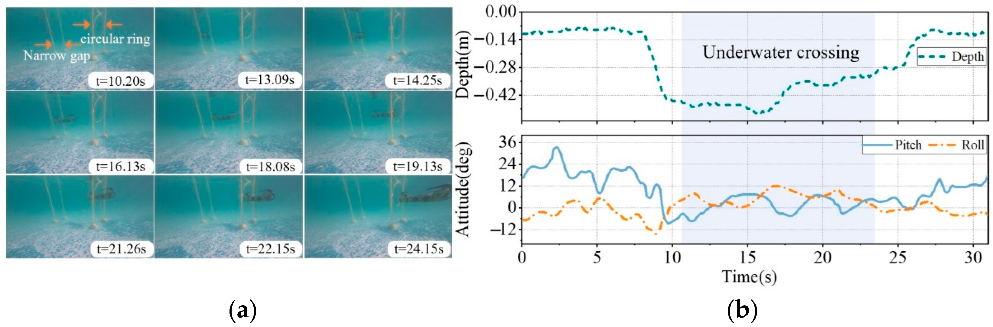
To assess the maneuverability of the tandem dual-rotor AAV underwater, we examined its capacity to navigate through narrow spaces. This was achieved by creating underwater obstacles, including narrow gaps and circular barriers. As seen in Figure 16a, two consecutive obstacles were positioned adjacent to each other at a distance of less than 2 m. The gap between the two rods was 0.3 m, and the diameter of the ring was 0.5 m; by using remote control to control underwater yaw attitude, the crossing of underwater obstacles can be realized.
The depth data and attitude change data of the AAV during the crossing process are depicted in Figure 16b. The experiment demonstrated that the pitch and roll angles of the AAV attitude vary within a range of 10 degrees while maintaining stable depth during underwater traversal. This success indicates that the AAV is capable of performing tasks in narrow spaces, which is a notable feature of the series layout of aerial aquatic vehicles.
5. Conclusions
This paper proposes a tandem dual-rotor AAV that enables cross-domain locomotion. Unlike most aerial–aquatic vehicles, it combines the low drag force advantages of underwater vehicles with the capability of cross-domain flight through a tandem dual-rotor design. The tandem dual-rotor AAV offers three key advantages. Firstly, the use of a composite power mode and a slender tandem layout reduces underwater drag force, increases underwater speeds, and enhances flight efficiency through the dual-rotor configuration. Secondly, the inclusion of roll thrusters ensures stability in the rolling direction, enabling underwater hovering and preventing subversion upon entry into the water. Lastly, the tail vector propulsion enhances flexibility and expands the potential for the tandem dual-rotor AAV to carry out missions in narrow waters.
This paper conducts theoretical analyses and prototype tests to validate the feasibility of the proposed tandem dual-rotor AAV scheme. Initially, aerial and underwater dynamics models for the tandem dual-rotor AAVs are formulated. Subsequently, building upon the conceptual design, the AAV’s structure is meticulously detailed, and the hardware configuration of the AAV system is delineated. To assess the effectiveness of flight and underwater control, traditional PID controllers are employed for simulation verification, confirming their efficacy in both modes of the AAV. Lastly, a prototype is constructed, and experiments including hovering flight, water entry tests, water surface maneuvering tests, and underwater traversal tests are conducted in diverse environments. A series of successful experiments validate the feasibility of the tandem dual-rotor AAV scheme.
However, there is still much room for improvement in this study. In future research, the structure will be further optimized, and the control algorithm of the tandem dual-rotor AAV will be explored in greater detail to achieve stability against wind drag force and underwater attitude. Moreover, underwater obstacle avoidance and navigation will be given further consideration to achieve the autonomous navigation of the tandem dual-rotor AAV once it enters the water.
Author Contributions
Conceptualization, S.W. (Sihuan Wu); methodology, S.W. (Sihuan Wu); software, M.S.; validation, S.W. (Sifan Wu); formal analysis, S.W. (Sihuan Wu) and Z.H.; investigation, S.W. (Sihuan Wu) and Z.H.; resources, Y.Y.; data curation, H.W.; writing—original draft preparation, S.W. (Sihuan Wu); writing—review and editing, S.W. (Sihuan Wu) and M.S.; visualization, M.S.; supervision, J.Z. and Y.Y.; project administration, J.Z.; funding acquisition, J.Z. All authors have read and agreed to the published version of the manuscript.
Funding
This research was funded by Southern Marine Science and Engineering Guangdong Laboratory grant number SML2023SP229.
Data Availability Statement
The datasets generated or analyzed during the current study are available from the corresponding author upon reasonable request.
Conflicts of Interest
The authors declare no conflict of interest.
References
- Sahoo, A.; Dwivedy, S.K.; Robi, P.S. Advancements in the field of autonomous underwater vehicle. Ocean Eng. 2019, 181, 145–160. [Google Scholar] [CrossRef]
- Wu, Y.; Duan, Y.; Wei, Y.; An, D.; Liu, J. Application of intelligent and unmanned equipment in aquaculture: A review. Comput. Electron. Agric. 2022, 199, 107201. [Google Scholar] [CrossRef]
- Rumson, A.G. The application of fully unmanned robotic systems for inspection of subsea pipelines. Ocean Eng. 2021, 235, 109214. [Google Scholar] [CrossRef]
- Zeng, Z.; Lyu, C.X.; Bi, Y.B.; Jin, Y.F.; Lu, D.; Lian, L. Review of hybrid aerial underwater vehicle: Cross-domain mobility and transitions control. Ocean Eng. 2022, 248, 110840. [Google Scholar] [CrossRef]
- Yao, G.C.; Li, Y.Z.; Zhang, H.Y.; Jiang, Y.T.; Wang, T.M.; Sun, F.C.; Yang, X.B. Review of hybrid aquatic-aerial vehicle (HAAV): Classifications, current status, applications, challenges and technology perspectives. Prog. Aerosp. Sci. 2023, 139, 100902. [Google Scholar] [CrossRef]
- Weisler, W.; Stewart, W.; Anderson, M.B.; Peters, K.; Gopalarathnam, A.; Bryant, M. Testing and characterization of a fixed wing cross-domain unmanned vehicle operating in aerial and underwater environments. IEEE J. Ocean. Eng. 2017, 43, 969–982. [Google Scholar] [CrossRef]
- Stewart, W.; Weisler, W.; Anderson, M.; Bryant, M.; Peters, K. Dynamic modeling of passively draining structures for aerial–aquatic unmanned vehicles. IEEE J. Ocean. Eng. 2019, 45, 840–850. [Google Scholar] [CrossRef]
- Rockenbauer, F.M.; Jeger, S.L.; Beltran, L.; Berger, M.; Harms, M.; Kaufmann, N.; Rauch, M.; Reinders, M.; Reinders, M.; Lawrance, N.; et al. Dipper: A Dynamically Transitioning Aerial-Aquatic Unmanned Vehicle. Robot. Sci. Syst. 2021, 48, 12–16. [Google Scholar]
- Alzu’bi, H.; Mansour, I.; Rawashdeh, O. Loon copter: Implementation of a hybrid unmanned aquatic–aerial quadcopter with active buoyancy control. J. Field Robot. 2018, 35, 764–778. [Google Scholar] [CrossRef]
- Liu, X.C.; Dou, M.H.; Huang, D.Y.; Wang, B.; Cui, J.Q.; Ren, Q.Y.; Dou, L.H.; Gao, Z.; Chen, J.; Chen, B.M. TJ-FlyingFish: Design and implementation of an aerial-aquatic quadrotor with tiltable propulsion units. In Proceedings of the IEEE International Conference on Robotics and Automation (ICRA), London, UK, 29 May–2 June 2023; pp. 7324–7330. [Google Scholar]
- Bai, Y.L.; Jin, Y.F.; Liu, C.H.; Zeng, Z.; Lian, L. Nezha-F: Design and Analysis of a Foldable and Self-Deployable HAUV. IEEE Robot. Autom. Lett. 2023, 8, 2309–2316. [Google Scholar] [CrossRef]
- Bi, Y.B.; Jin, Y.F.; Lyu, C.X.; Zeng, Z.; Lian, L. Nezha-Mini: Design and Locomotion of a Miniature Low-Cost Hybrid Aerial Underwater Vehicle. IEEE Robot. Autom. Lett. 2022, 7, 6669–6676. [Google Scholar] [CrossRef]
- Chen, Q.; Zhu, D.; Liu, Z. Attitude control of aerial and underwater vehicles using single-input FUZZY P+ ID controller. Appl. Ocean Res. 2021, 107, 102460. [Google Scholar] [CrossRef]
- Horn, A.C.; Pinheiro, P.M.; Grando, R.B.; da Silva, C.B.; Neto, A.A.; Drews, P.L. A novel concept for hybrid unmanned aerial underwater vehicles focused on aquatic performance. In Proceedings of the 2020 Latin American Robotics Symposium (LARS), 2020 Brazilian Symposium on Robotics (SBR) and 2020 Workshop on Robotics in Education (WRE), Natal, Brazil, 9–13 November 2020; pp. 1–6. [Google Scholar]
- Wang, X.; Shi, Y.; Pan, G.; Chen, X.; Zhao, H. Numerical research on the high-speed water entry trajectories of AUVs with asymmetric nose shapes. Ocean Eng. 2021, 234, 109274. [Google Scholar] [CrossRef]
- Mitra, A.; Panda, J.P.; Warrior, H.V. Experimental and numerical investigation of the hydrodynamic characteristics of autonomous underwater vehicles over sea-beds with complex topography. Ocean Eng. 2020, 198, 106978. [Google Scholar] [CrossRef]
- Luo, W.Z.; Jiang, D.P.; Wu, T.C.; Liu, M.Y.; Li, Y.L. Numerical simulation of the hydrodynamic characteristics of unmanned underwater vehicles near ice surface. Ocean Eng. 2022, 253, 111304. [Google Scholar] [CrossRef]
- Qin, Y.M.; Xu, W.; Lee, A.; Zhang, F. Gemini: A compact yet efficient bi-copter uav for indoor applications. IEEE Robot. Autom. Lett. 2020, 5, 3213–3220. [Google Scholar] [CrossRef]
- Chen, M.T.; Shen, J.W.; Hubner, J.P. Investigation of Fountain Effect in Dual-Rotor/Wing Interaction at Low Reynolds Number. In Proceedings of the AIAA AVIATION 2022 Forum, Chicago, IL, USA, 27 June–1 July 2022; p. 3816. [Google Scholar]
- Chen, J.; Zhu, Q.; Wang, K.; Zhu, Z.; Shen, S. Aerodynamic characteristics analysis of twin-rotor in tandem helicopter. Adv. Aeronaut. Sci. Eng. 2020, 11, 167–176. [Google Scholar]
- Guerrero, J.; Torres, J.; Creuze, V.; Chemori, A.; Campos, E. Saturation based nonlinear PID control for underwater vehicles: Design, stability analysis and experiments. Mechatronics 2019, 61, 96–105. [Google Scholar] [CrossRef]
- Zhang, Q.; Liu, Z.; Zhao, J.; Zhang, S. Modeling and attitude control of bi-copter. In Proceedings of the 2016 IEEE International Conference on Aircraft Utility Systems (AUS), Beijing, China, 10–12 October 2016; pp. 172–176. [Google Scholar]
- Liang, J.; Liang, J.; Huang, W.; Zhou, F.; Lin, G.; Su, Z. Robust nonlinear path-tracking control of vector-propelled AUVs in complex sea conditions. Ocean Eng. 2023, 274, 113923. [Google Scholar] [CrossRef]
- Ryll, M.; Bülthoff, H.H.; Giordano, P.R. Modeling and control of a quadrotor UAV with tilting propellers. In Proceedings of the 2012 IEEE International Conference on Robotics and Automation, St. Paul, MN, USA, 14–18 May 2012; pp. 4606–4613. [Google Scholar]
Figure 1.
Schematic diagram of tandem dual-rotor aerial–aquatic vehicle process and application scenario.
Figure 1.
Schematic diagram of tandem dual-rotor aerial–aquatic vehicle process and application scenario.
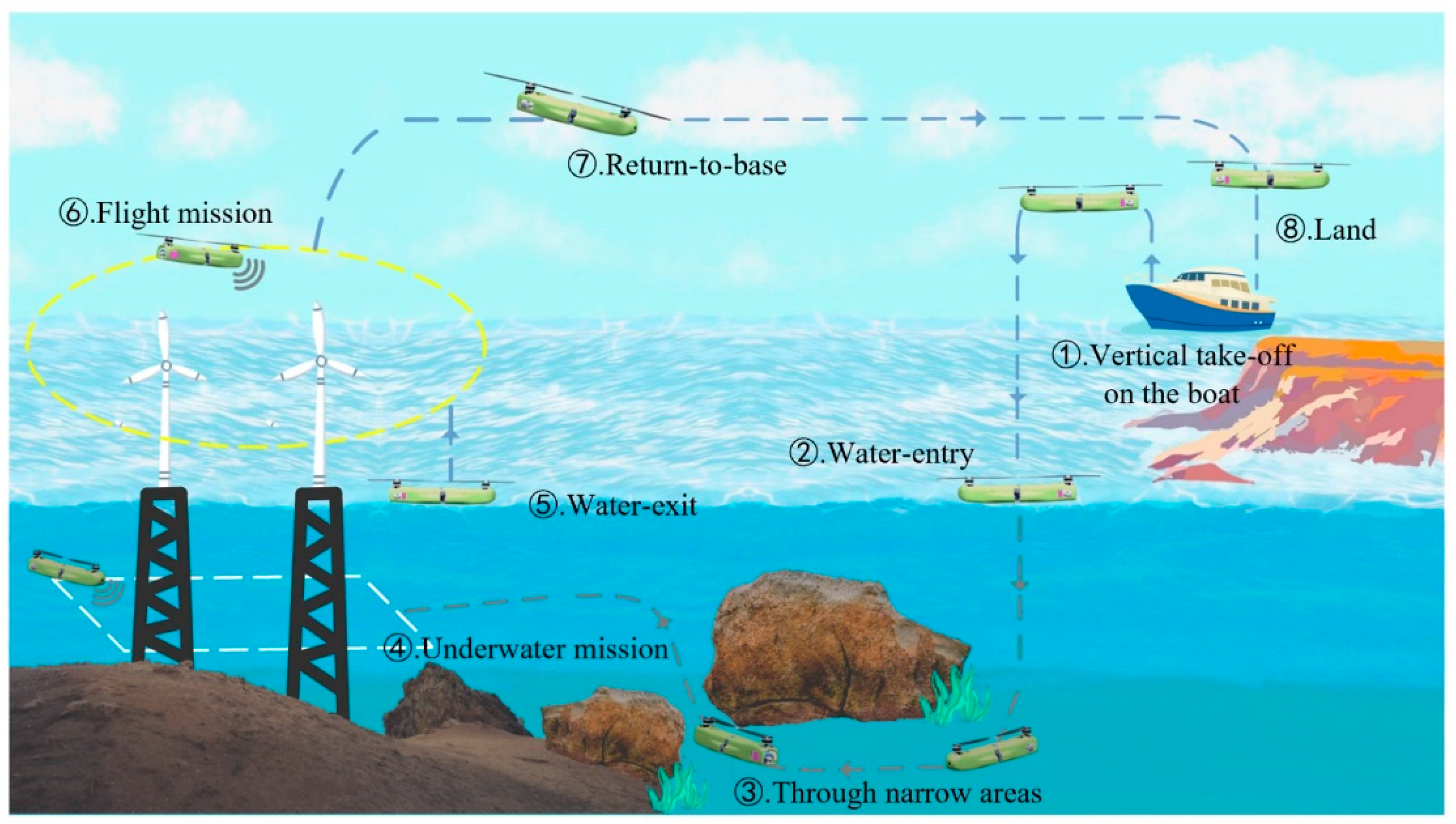
Figure 2.
A tandem twin-rotor AAV design layout display and size annotation. (a) Overall 3D structure and external device location display. (b) Schematic diagram of internal structure and equipment installation. (c) Top view and size display. (d) Rear view and size display.
Figure 2.
A tandem twin-rotor AAV design layout display and size annotation. (a) Overall 3D structure and external device location display. (b) Schematic diagram of internal structure and equipment installation. (c) Top view and size display. (d) Rear view and size display.
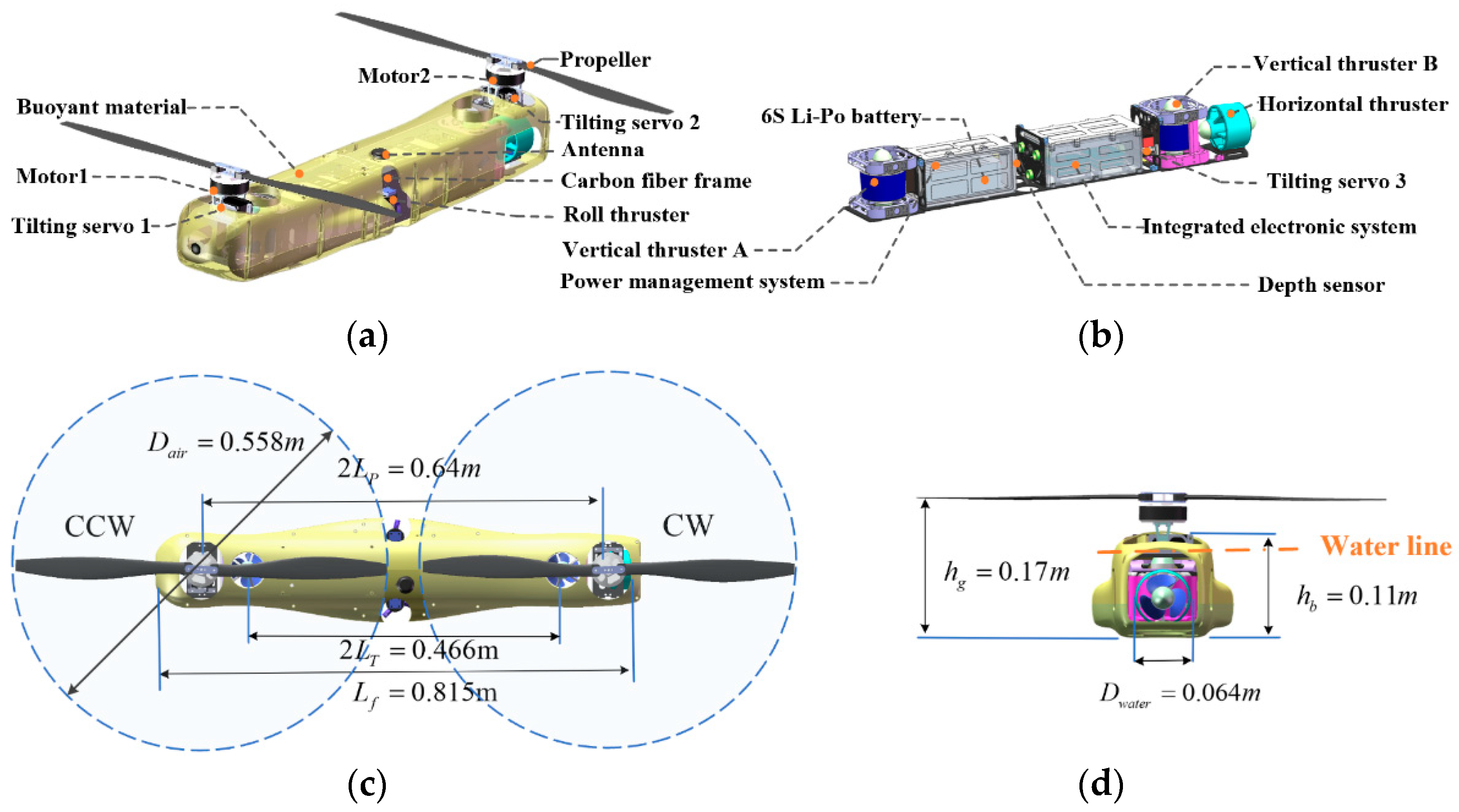
Figure 3.
Model of the tandem twin-rotor AAV with the marks on the body coordinate systems and inertial coordinate system.
Figure 3.
Model of the tandem twin-rotor AAV with the marks on the body coordinate systems and inertial coordinate system.
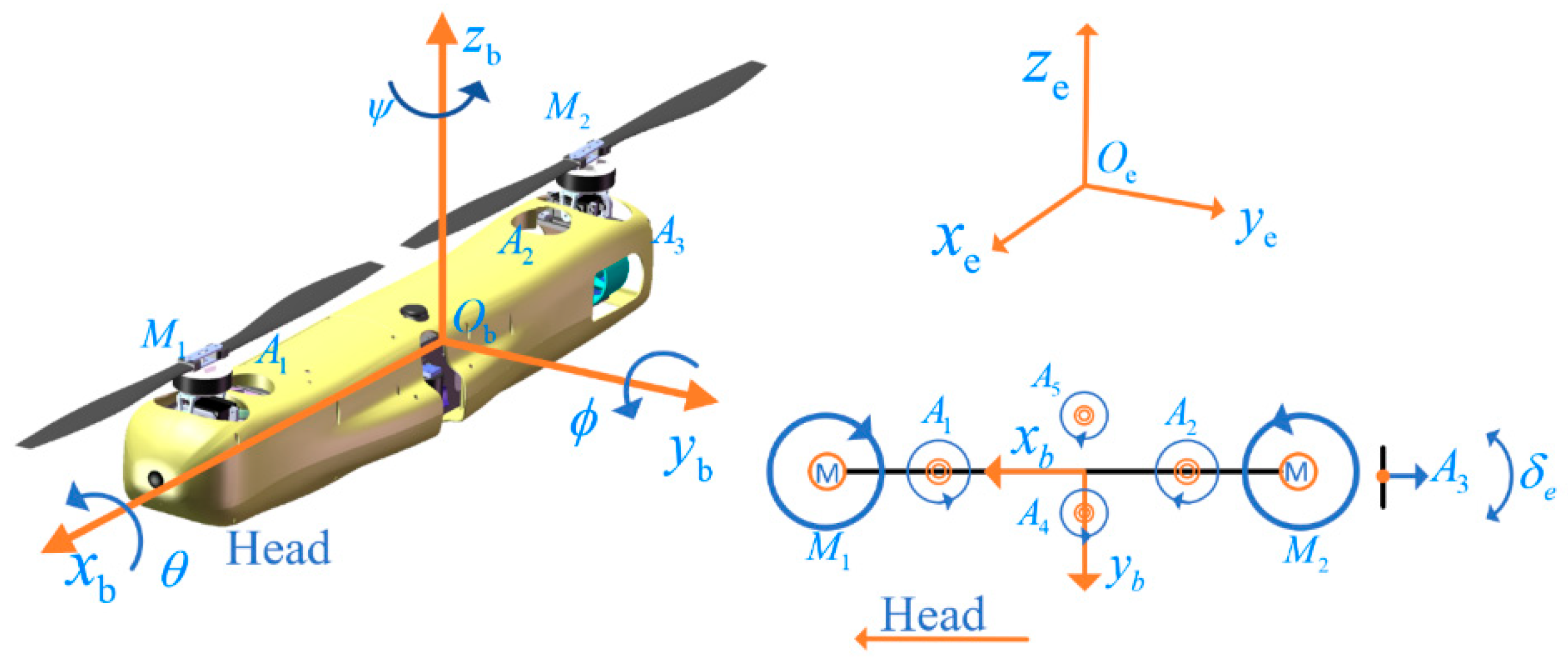
Figure 4.
Principles of tandem dual-rotor AAV motion control. (a) Principle of roll motion. (b) Principle of yaw motion. (c) Principle of pitch motion.
Figure 4.
Principles of tandem dual-rotor AAV motion control. (a) Principle of roll motion. (b) Principle of yaw motion. (c) Principle of pitch motion.
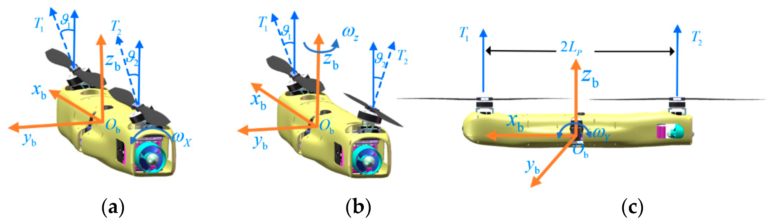
Figure 5.
Principles of underwater motion control.
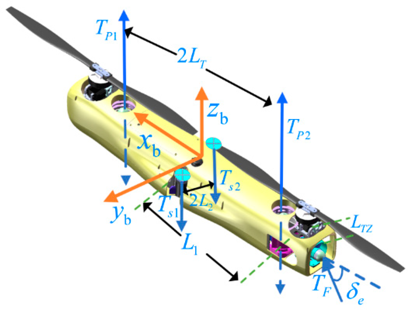
Figure 6.
Control block diagram of the tandem twin-rotor AAV.
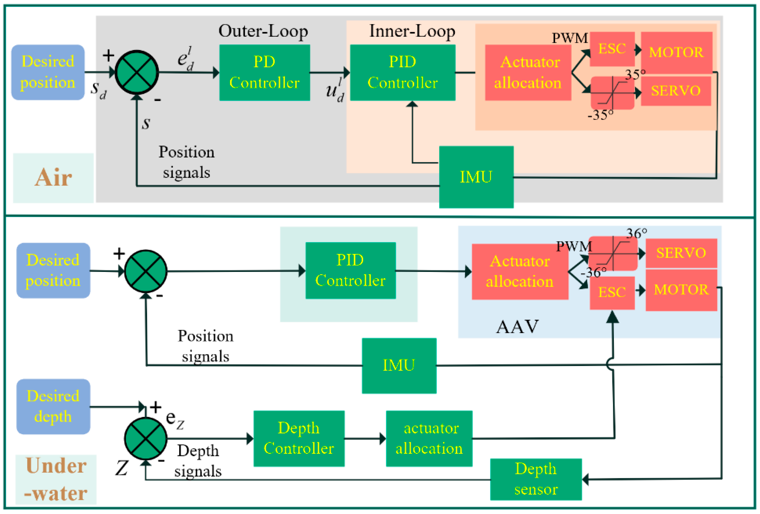
Figure 7.
PID control simulation of AAV flight and hover process of the AAV.

Figure 8.
Control simulation result of the tandem twin-rotor AAV. (a) PID control simulation of AAV three-dimensional trajectory tracking (b) trajectory tracking error.
Figure 8.
Control simulation result of the tandem twin-rotor AAV. (a) PID control simulation of AAV three-dimensional trajectory tracking (b) trajectory tracking error.

Figure 9.
Prototype and mass distribution of the tandem twin-rotor AAV. (a) No buoyancy material housing prototype; the shell of the design was replaced by a block buoyant material, and two states of propeller folding and unfolding are shown. (b) Mass distribution and mass proportion.
Figure 9.
Prototype and mass distribution of the tandem twin-rotor AAV. (a) No buoyancy material housing prototype; the shell of the design was replaced by a block buoyant material, and two states of propeller folding and unfolding are shown. (b) Mass distribution and mass proportion.
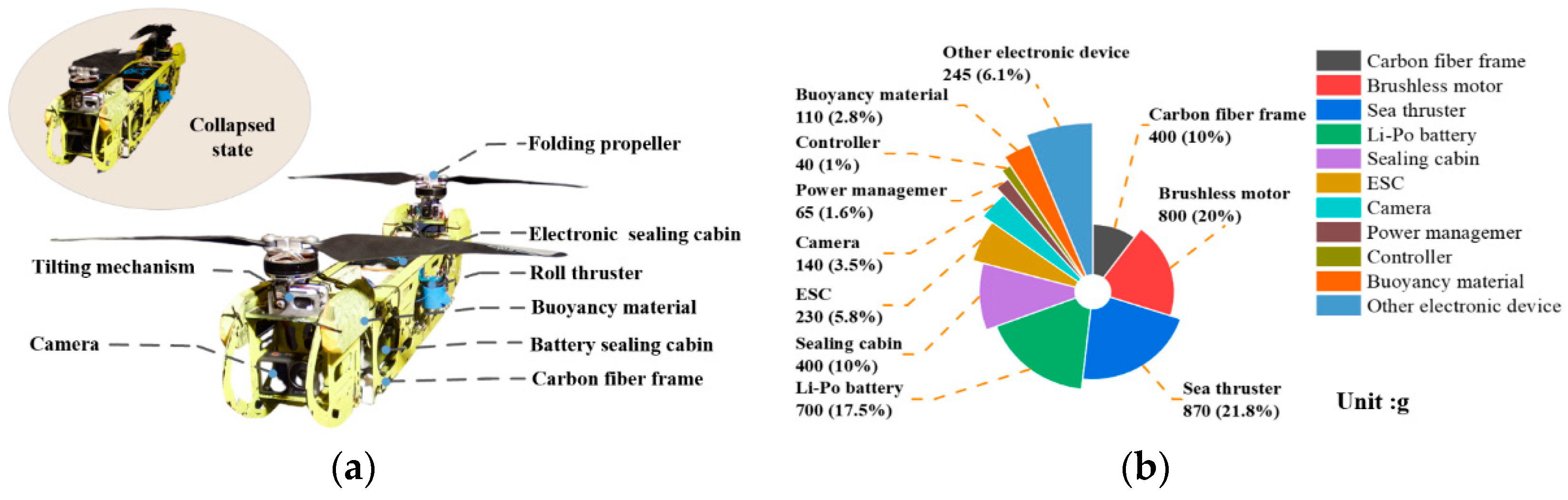
Figure 10.
Composition of integrated electronic system of the tandem twin-rotor AAV.

Figure 11.
(a) Static thrust and power consumption of the propulsion system at different PWM inputs. (b) Actual PWM output of the two motors during surface takeoff and air flight. (c) Schematic diagram of the effective area of two non-overlapping twin rotors.
Figure 11.
(a) Static thrust and power consumption of the propulsion system at different PWM inputs. (b) Actual PWM output of the two motors during surface takeoff and air flight. (c) Schematic diagram of the effective area of two non-overlapping twin rotors.
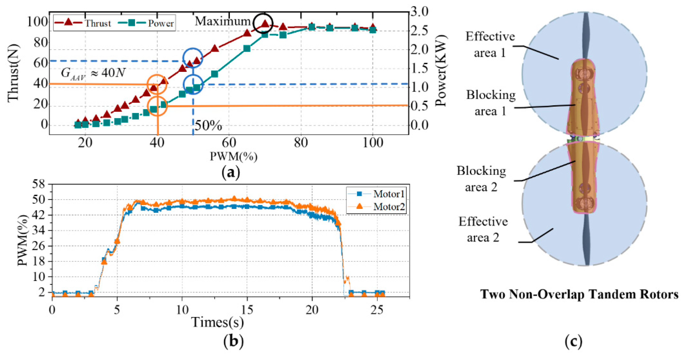
Figure 12.
Outdoor hover test of the tandem twin-rotor AAV. (a) Hover flight test over water. (b) Latitude, longitude, and altitude data graph, and hover attitude data graph, roll, pitch and yaw.
Figure 12.
Outdoor hover test of the tandem twin-rotor AAV. (a) Hover flight test over water. (b) Latitude, longitude, and altitude data graph, and hover attitude data graph, roll, pitch and yaw.
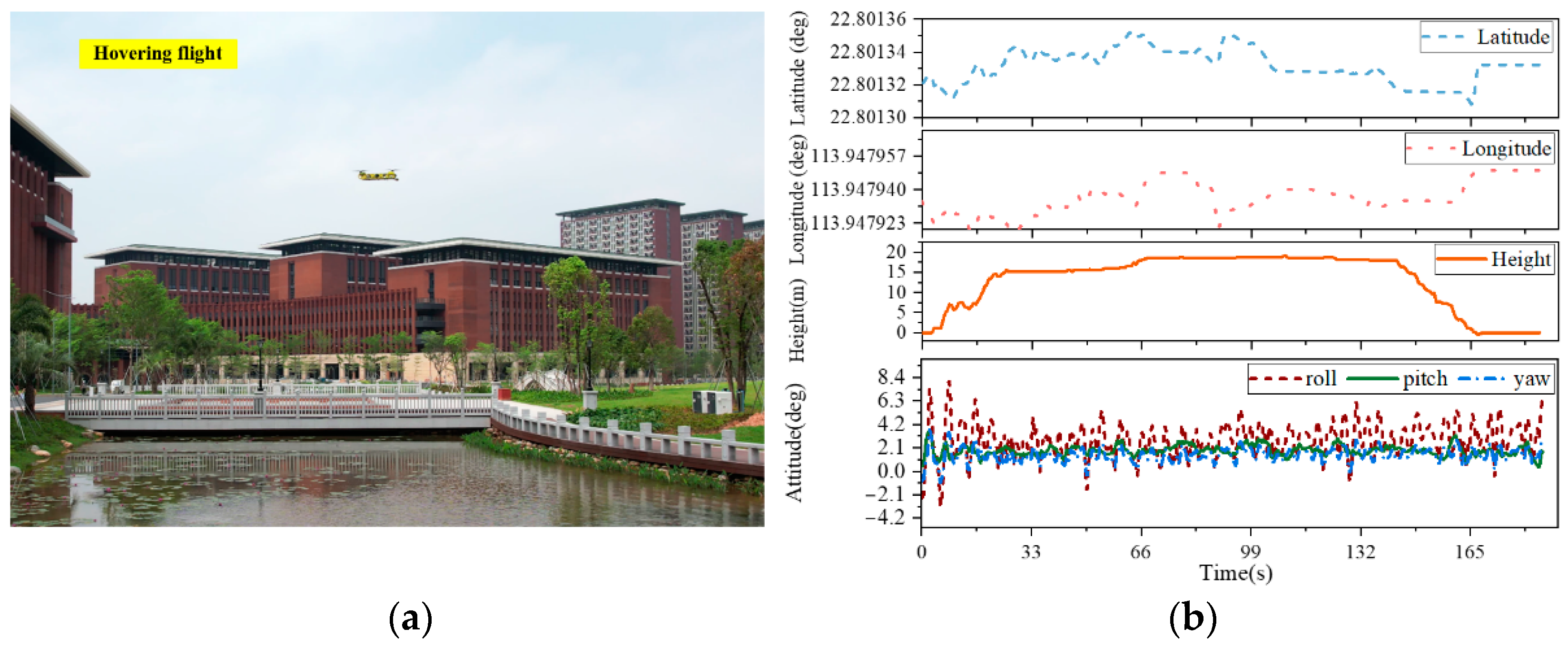
Figure 13.
Full-mission experiment. (a) The process of water entry. (b) Depth and attitude data diagram of the water entry and water exit process; blue represents the process underwater. (c) The process of water exit.
Figure 13.
Full-mission experiment. (a) The process of water entry. (b) Depth and attitude data diagram of the water entry and water exit process; blue represents the process underwater. (c) The process of water exit.
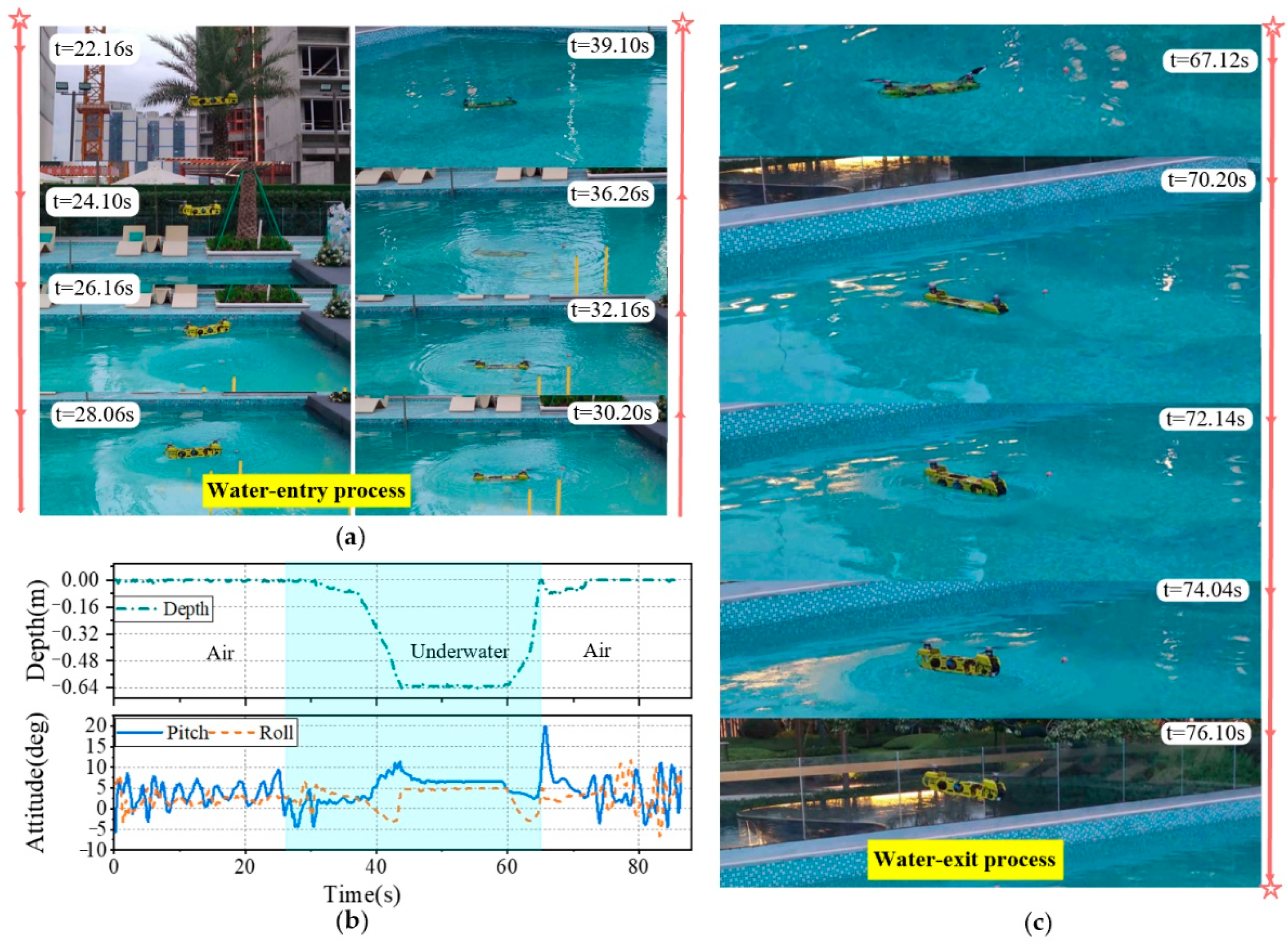
Figure 14.
Outdoor test of the tandem twin-rotor AAV. (Ⅰ) Take off from rocks on the ground. (Ⅱ) Flight and flight perspective. (Ⅲ) Water entry and underwater perspective. (Ⅳ) Water exit and underwater perspective. (Ⅴ) Return back.
Figure 14.
Outdoor test of the tandem twin-rotor AAV. (Ⅰ) Take off from rocks on the ground. (Ⅱ) Flight and flight perspective. (Ⅲ) Water entry and underwater perspective. (Ⅳ) Water exit and underwater perspective. (Ⅴ) Return back.

Figure 15.
(a) The process of an “S”-shaped path swimming on the water surface. (b) Data diagram of the tandem twin-rotor AAV attitude and tail thruster tilting angle.
Figure 15.
(a) The process of an “S”-shaped path swimming on the water surface. (b) Data diagram of the tandem twin-rotor AAV attitude and tail thruster tilting angle.
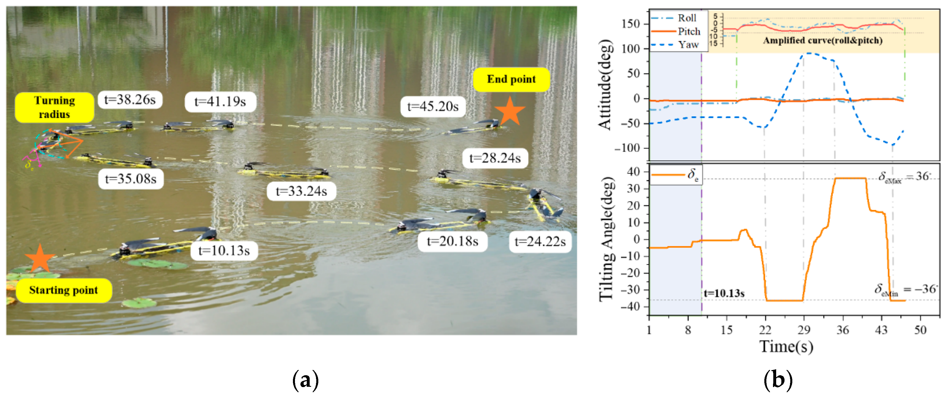
Figure 16.
The process of moving underwater and crossing the gap. (a) The process of through the narrow gap and circular ring. (b) A data diagram of AAV depth information during underwater motion, and a data diagram of attitude when crossing the narrow gap.
Figure 16.
The process of moving underwater and crossing the gap. (a) The process of through the narrow gap and circular ring. (b) A data diagram of AAV depth information during underwater motion, and a data diagram of attitude when crossing the narrow gap.
Disclaimer/Publisher’s Note: The statements, opinions and data contained in all publications are solely those of the individual author(s) and contributor(s) and not of MDPI and/or the editor(s). MDPI and/or the editor(s) disclaim responsibility for any injury to people or property resulting from any ideas, methods, instructions or products referred to in the content. |
© 2024 by the authors. Licensee MDPI, Basel, Switzerland. This article is an open access article distributed under the terms and conditions of the Creative Commons Attribution (CC BY) license (https://creativecommons.org/licenses/by/4.0/).
Share and Cite
MDPI and ACS Style
Wu, S.; Shao, M.; Wu, S.; He, Z.; Wang, H.; Zhang, J.; You, Y. Design and Demonstration of a Tandem Dual-Rotor Aerial–Aquatic Vehicle. Drones 2024, 8, 100. https://doi.org/10.3390/drones8030100
AMA Style
Wu S, Shao M, Wu S, He Z, Wang H, Zhang J, You Y. Design and Demonstration of a Tandem Dual-Rotor Aerial–Aquatic Vehicle. Drones. 2024; 8(3):100. https://doi.org/10.3390/drones8030100
Chicago/Turabian StyleWu, Sihuan, Maosen Shao, Sifan Wu, Zhilin He, Hui Wang, Jinxiu Zhang, and Yue You. 2024. "Design and Demonstration of a Tandem Dual-Rotor Aerial–Aquatic Vehicle" Drones 8, no. 3: 100. https://doi.org/10.3390/drones8030100