

The Mamba: A Suspended Manipulator to Sample Plants in Cliff Environments

Createk Design Lab, Interdisciplinary Institute for Technological Innovation, University of Sherbrooke, Sherbrooke, QC J1K 0A5, Canada
*
Author to whom correspondence should be addressed.
Drones 2024, 8(4), 139; https://doi.org/10.3390/drones8040139
Submission received: 25 January 2024
/
Revised: 7 March 2024
/
Accepted: 27 March 2024
/
Published: 3 April 2024
(This article belongs to the Special Issue Drones in the Wild)
Abstract
:Conservation efforts in cliff habitats pose unique challenges due to their inaccessibility, limiting the study and protection of rare endemic species. This project introduces a novel approach utilizing aerial manipulation through a suspended manipulator attached with a cable under a drone to address these challenges. Unlike existing solutions, the Mamba provides a horizontal reach up to 8 m to approach cliffs while keeping the drone at a safe distance. The system includes a model-based control system relying solely on an inertial measurement unit (IMU), reducing sensor requirements and computing power to minimize overall system mass. This article presents novel contributions such as a double pendulum dynamic modeling approach and the development and evaluation of a precise control system for sampling operations. Indoor and outdoor tests demonstrate the effectiveness of the suspended aerial manipulator in real-world environments allowing the collection of 55 samples from 28 different species. This research signifies a significant step toward enhancing the efficiency and safety of conservation efforts in challenging cliff habitats.
1. Introduction
Cliff habitats remain extremely difficult to access by conservation scientists. These unique habitats are home to flora and fauna that have been little studied over the years due to the difficulty of accessing them safely. Still, many conservation efforts are being made in these habitats since it is an environment that is minimally disturbed by invasive species and home to many rare endemic species. Many invasive species have a detrimental effect on the flora of Kaua’i in the Hawaiian archipelago where 97% of endemic species are now considered endangered, critically endangered, or extinct. On the island of Kaua’i for example, many organizations such as the National Tropical Botanical Garden (NTBG), the Plant Extinction Prevention Program (PEPP), and the State’s Division of Forestry and Wildlife of Hawai’i have been studying this habitat for some time using drone imagery, abseiling, climbing, etc. Despite their recent successes in the rediscovery of supposedly extinct plant species [1] and the discovery of new plant populations [2,3], the difficulties encountered by scientists to physically reach these plants is a barrier to conservation work. Indeed, the ultimate objective would be to perform a complete conservation cycle including the localization of the species of interest, the collection of propagating material (cuttings, flowers, seeds), the cultivation in specialized nurseries, and the reintroduction in their natural habitat. At the moment, the collection and propagation steps still represent major challenges on most cliff environments with the methods and the tools at their disposal.
Drones are widely used for imaging applications in various fields such as infrastructure inspection [4,5], forestry [6,7], and agriculture [8,9], and thanks to technological advances in recent years, aerial manipulation represents a new field of research that is rapidly emerging. As such, drones are now used to perform tasks in contact with their environment. This emerging field of research brings many new possibilities for work carried out at height or in areas that are considered dangerous to humans. Some projects have succeeded in demonstrating the usefulness of aerial manipulation for the installation of sensors [10,11,12], as well as the inspection of bridges [13,14,15], metal pipes [16,17], or high-voltage power lines [18]. For all these tasks, the aerial manipulator must be able to apply and maintain forces on a surface. Some projects have proposed solutions where a serial robotic arm with several degrees of freedom (DOF) is fixed rigidly on a drone [19,20]. This makes it possible to have great dexterity which opens the way to many manipulation applications. However, such solutions bring several constraints in the design of an aerial manipulator. Serial robotic arms are usually not designed to be lightweight since they are optimized toward precision, and usually comes with stiffness criteria and multiple oversized actuators to be able to produce sufficient torque to move the entire arm. Other projects have sought to reduce this added mass by using parallel manipulators installed under the drone [21] or by using less complex serial robotic arms with 1-DOF [12,16]. However, some drawbacks are still present with these configurations. As with any manipulator rigidly attached to a drone, each movement or contact of the manipulator causes a resulting torque on the drone which can destabilize it and diminish the precision during the manipulation task. Some projects have developed control systems taking this interaction into account to ensure the stability of the drone [12]. However, aerial manipulators using robotic arms rigidly attached to drones also generally have a limited range to keep the system center of mass within the footprint of the actuators. Aerial manipulator design must also limit the manipulator’s range to limit the total inertia of the system which greatly helps to preserve a certain level of dexterity for the whole aerial system. This limited range might increase the risk of a collision in natural environments such as cliffs which have various shapes in addition to being covered with plants and trees.
Drones are widely used for imaging applications in various fields such as infrastructure inspection [4,5], forestry [6,7], and agriculture [8,9], and thanks to technological advances in recent years, aerial manipulation represents a new field of research that is rapidly emerging. As such, drones are now used to perform tasks in contact with their environment. This emerging field of research brings many new possibilities for work carried out at height or in areas that are considered dangerous to humans. Some projects have succeeded in demonstrating the usefulness of aerial manipulation for the installation of sensors [10,11,12], as well as the inspection of bridges [13,14,15], metal pipes [16,17], or high-voltage power lines [18]. For all these tasks, the aerial manipulator must be able to apply and maintain forces on a surface. Some projects have proposed solutions where a serial robotic arm with several degrees of freedom (DOF) is fixed rigidly on a drone [19,20]. This makes it possible to have great dexterity which opens the way to many manipulation applications. However, such solutions bring several constraints in the design of an aerial manipulator. Serial robotic arms are usually not designed to be lightweight since they are optimized toward precision, and usually comes with stiffness criteria and multiple oversized actuators to be able to produce sufficient torque to move the entire arm. Other projects have sought to reduce this added mass by using parallel manipulators installed under the drone [21] or by using less complex serial robotic arms with 1-DOF [12,16]. However, some drawbacks are still present with these configurations. As with any manipulator rigidly attached to a drone, each movement or contact of the manipulator causes a resulting torque on the drone which can destabilize it and diminish the precision during the manipulation task. Some projects have developed control systems taking this interaction into account to ensure the stability of the drone [12]. However, aerial manipulators using robotic arms rigidly attached to drones also generally have a limited range to keep the system center of mass within the footprint of the actuators. Aerial manipulator design must also limit the manipulator’s range to limit the total inertia of the system which greatly helps to preserve a certain level of dexterity for the whole aerial system. This limited range might increase the risk of a collision in natural environments such as cliffs which have various shapes in addition to being covered with plants and trees.
On the other hand, aerial systems developed to sample treetop branches generally rely on passive manipulators suspended under the drone [22,23]. These manipulators located between 3 to 5 m below the drone at the end of a rod offer the advantage of keeping the drone away from the top of the tree during the sampling operation. This concept reduces the risk of collisions which could lead to a crash. Although these manipulators can collect branches from the tops of trees, they are not designed to perform tasks requiring high precision as any drone movement induces an uncontrolled pendulum oscillation on the suspended manipulator. Recently, another axis of research in aerial manipulation concerns manipulators suspended by cable and equipped with actuators [24,25]. This configuration brings many advantages. As the system hangs under a drone, it keeps the drone away from any obstacle. It also offers a great number of possibilities for the placement and orientation of the actuators since the suspended manipulator does not have to generate thrusts to fight gravity. Decoupling the system in this way offers more possibilities in the design of the manipulator. However, most of the suspended manipulator behaves as a double pendulum which brings many challenges to the design of a control system. Double pendulums exhibit chaotic behavior, have multiple oscillation modes, and their dynamics are more complex than a simple pendulum.
Ref. [25] relies on such a suspended manipulator equipped with four propellers, a winch to control vertical movements, and a 1-DOF manipulator to perform pick and place operations. This concept is composed of two cables to suspend the manipulator and allows a passive stabilization of the yaw rotational movement. This also prevents the double pendulum dynamics on the pitch axis that brings a second mode of oscillation. Using classical control theory with proportional-derivative controllers (PD), the control system relied on the data coming from the accelerometer that were filtered and integrated to obtain the linear velocities of the platform. Ref. [26] improved the system by using a Linear Quadratic Controller (LQR) based on a single pendulum model which was relying on a multi-sensor approach (i.e., accelerometer, computer vision). With both control systems, one axis still showed the behavior of a double pendulum as the two wires design only prevented a second oscillation mode in the pitch axis, but not in the roll orientation which greatly affects the capacity of the platform to stabilize itself efficiently. Ref. [24] is another example of this suspended manipulator concept. This aerial manipulator is equipped with a winch for each of the three suspension cables, 6 inclined brushless direct current (BLDC) motors with propellers and a 7-joints robotics arm. The system presented is over-actuated and has an overall mass of 45 kg. This system offers precision to perform a wide range of tasks when suspended under a crane or a fixed anchor. Ref. [27] has developed a model for this platform to dampen the oscillation of the platform while dealing with a perturbation. To approach this problem, the system is modeled as a double pendulum and a low pass filter is used to differentiate the two modes of the system. An optimal linear LQR controller is then used to control both oscillation modes. The system can stabilize in 6 s at its equilibrium point. Using a low pass filter may be problematic in a case where the system has two frequencies close to each other. Also, the delay induced by the filter might affect the control system if great precision or a high bandwidth is required.
Although these two concepts of suspended manipulators are fulfilling aerial manipulation needs they were designed for, they have some drawbacks for cliff sampling application as they were designed to operate at their equilibrium point, and their transient response is not as fast and precise as needed to perform plant sampling. This article proposes new contributions to the design of suspended manipulators such as a reliable model of the system for dynamic simulation and tuning, and a model-based control system solely relying on an inertial measurement unit (IMU) which enables manipulation tasks requiring high precision and high bandwidth. The approach taken in this project is to keep the drone away from any obstacle by designing a suspended manipulator that has an extended horizontal reach to approach the cliff while keeping the drone away from it as presented in our previous article [28] that covers the mechanical design of the suspended manipulator. It is essential to position the system with high precision to collect plant samples on cliffs. To obtain such a precision, it appeared essential to be able to stabilize the system’s second mode of oscillation. Furthermore, given the environment and the topography in which the sampling operations must take place, the system cannot rely on external signals to ensure its positioning (i.e., GNSS) [29]. Finally, the system must use a limited number of sensors and computing power to minimize the total mass of the system which must be suspended under a drone. Following these requirements, a suspended manipulator comprising a model-based control system was developed and tested in a real-world environment.
This article is divided as follows: Section 2 presents the system design based on the sampling operation requirements, the modeling of the system, and the design and evaluation of the control system for the suspended manipulator to perform operations requiring precision. Indoor and outdoor tests of the suspended aerial manipulator are presented and analyzed in depth in Section 3. Finally, the results are discussed in Section 4.
2. Material and Methods
2.1. System Design
Past research projects have already demonstrated the advantages of using a suspended manipulator to keep a vertical clearance between a drone and any obstacles while minimizing the transmission of destabilizing moment to the drone during the manipulation operation [22,23,24,25]. However, the suspended manipulator workspace of these systems is limited and located directly under the lifting system. Usually, the lifting system moves the suspended manipulator as the latter uses its actuators to stabilize itself at its equilibrium point directly under the lifting system. The objective of the concept described here is to bring the whole system in close vicinity of the cliff, and then, to move only the suspended manipulator to perform a sampling operation on the targeted plant as shown in Figure 1. The main advantage of this strategy is that the drone maintains a horizontal and vertical safety distance with surrounding obstacles, while the platform can move with great precision to accomplish the sampling task. This design choice also aims to minimize the impact on the flight performance of the lifting drone, similarly to the suspended manipulator concepts presented earlier [28]. The length of the rope determines the reach of the suspended manipulator during the sampling operation. However, the added range with longer rope comes at the expense of a loss in positioning accuracy. The design of such a suspended manipulator must meet two main requirements to ensure the success of the sampling operation. The system must be able to move independently from the drone and to position its end effector with enough precision to collect plant material. This section gives an overview of the Mamba design. The suspended manipulator design was based on the initial version of the system which is presented in [28], this section presents changes that have been made to the system since the previous version.
To ensure positioning precision the suspended manipulator must have the ability to control a minimum of 3-DOF using 3 forces or torques independently from the drone: (1) a bidirectional longitudinal force (2) a bidirectional lateral force, and (3) a bidirectional yaw torque. Since the platform does not have to counter gravity, this leaves greater flexibility in the positioning of the actuators. The concept shown in Figure 1 enhances the platform performances by allowing thrusters in the horizontal plane of the suspended manipulator and perpendicularly oriented. These actuators should produce bidirectional thrust, while also having sufficient bandwidth to react quickly to external perturbations while controlling the different modes of the system. By having the thrusters in pairs located on each side of the center of mass (CoM), forces and torques can be produced more efficiently on the CoM. This configuration also keeps a distance between the front thruster and the end-effector to avoid any damage to the targeted plants. In this design the actuators located at the rear end of the platform produce the longitudinal forces, while the others are responsible for creating both the lateral force, and the yaw moment.
Different propulsion configurations were considered for the suspended manipulator to produce bi-directional thrust in [30]. The antagonist actuator configuration consists of two motors positioned to produce thrust in opposite directions. At all times, the motors are at least idling with one of the motors speeding to produce thrust. This strategy makes it possible to avoid the dead zone associated with the reversal of BLDC motors and the time required to produce large swings in angular momentum with limited torque. The antagonist configuration provides a major advantage in terms of bandwidth when compared to a single sensorless BLDC motor reversing its thrust as it does not deal with the actuator dead-zone at zero velocity. The chosen antagonist configuration has a force bandwidth of 5.4 Hz. Figure 2 shows the position of all the components installed on the suspended manipulator.
The Mamba is powered by a 6S LiPo battery (22.2 V) with a capacity of (2250 mAh) giving it 30 min of autonomy. BLDC motors (2310 Badass, Kv = 900) with 17.8 cm propellers (10.2 cm fixed-pitch) were selected for the actuators acting along the x-axis. BLDC motors (2305 Badass, Kv = 1050) with 12.7 cm propellers (11.4 cm fixed-pitch) were selected for the actuators acting in the y-direction. The electronic system of the suspended platform is built around a CUAV X7 Pro flight controller that uses a customized version of the Ardupilot firmware [31], and allows a seamless integration of the control system and the motor mixer to account for the antagonist actuator configuration. As the system is teleoperated, a Herelink digital transmission system is used to transmit the full HD feed coming from the on-board camera. A custom sampling mechanism and its cutting controller were designed as presented in [28], and installed at one end of the longitudinal tube. Figure 3 provides an overview of all the components installed on the Mamba.
2.2. Model
Previous work used different approaches to model suspended manipulators by simplifying the system to a simple pendulum model [25] or by accounting for the two oscillation modes of the system using a low pass filter to estimate the states of the system [27]. Here we present a different approach based on a dynamic model designed to simulate the behavior of the sampling platform as a double pendulum with the objective to use it for a model-based control system. This section introduces the needed model to accurately predict the behavior of this suspended manipulator as it moves outside of its equilibrium point to perform a sampling operation.
Some assumptions were considered while elaborating the model. The anchor position, which is located at the junction of the drone and the cable, is considered fixed in space as the drone will be hovering during the sampling operation. The cables are considered rigid frames with no mass as their mass is negligible when compared to the suspended manipulator. We also considered the actuators and gravity as the only external forces on the system. Since the sampling phase of the operation is performed quasi-statically, aerodynamic drag force is neglected. The products of inertia are considered as zero because the suspended manipulator’s principal axes mostly coincide with the coordinate axes. Also, the suspended manipulator is considered as a rigid body.
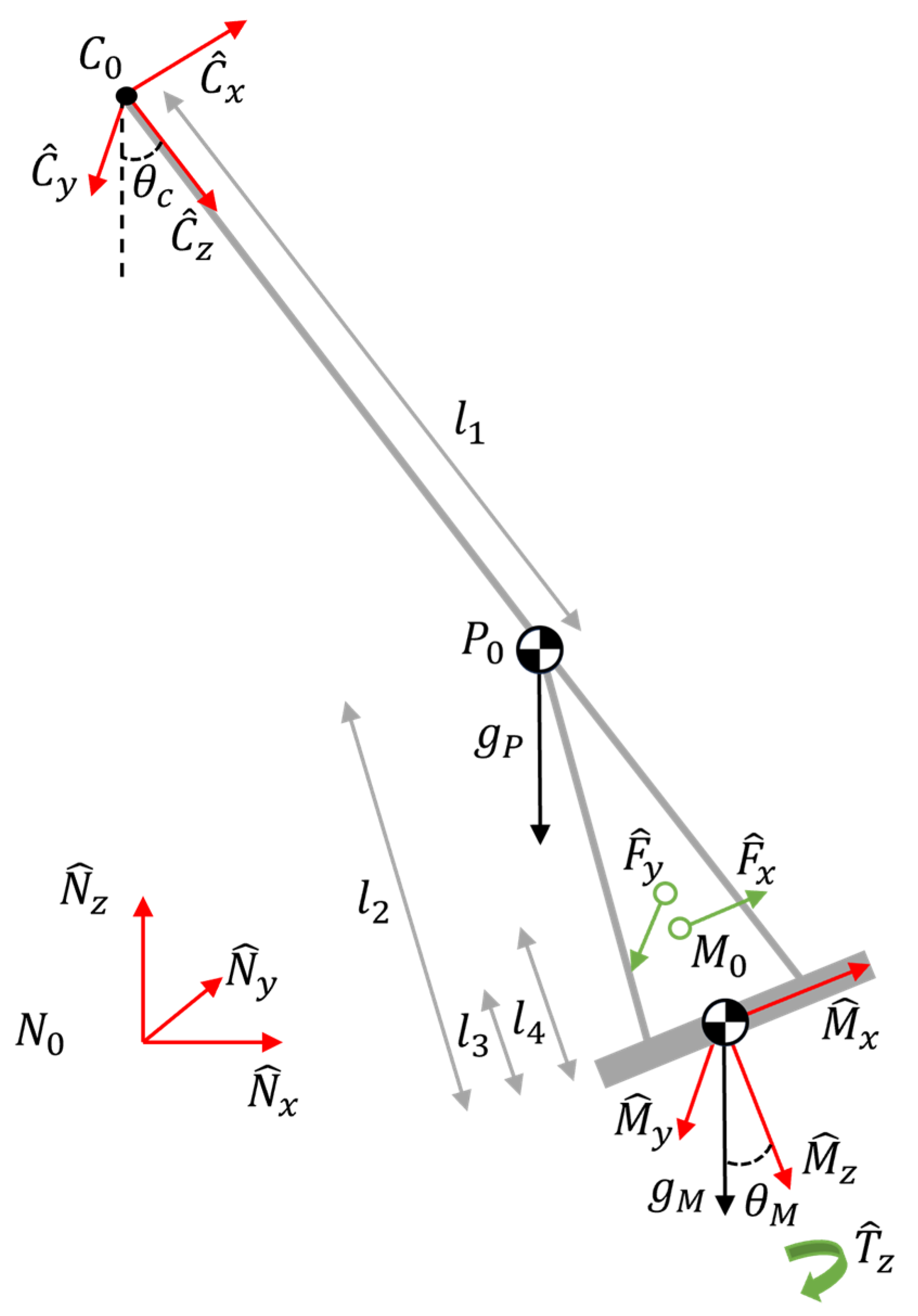
The model of the system, shown in Figure 4, can be placed in a Newtonian frame N, and it is composed of a rigid frame C representing the cable with its origin C0 located at the anchor point on the lifting system, and a rigid body M representing the manipulator with its origin located on the suspended manipulator CoM. To achieve a good representation of the physical system and the carabiner used to attach the suspended manipulator to the cable, a mass at the pivot point is considered, and is represented by a particle located at P0. The point P0 is located at a distance L1 from C0, while the CoM of body M is located at a L2 distance from P0. Using these frames and bodies, the suspended manipulator can be modeled as a spherical double pendulum with a first pendulum composed of the cable between the drone and the particle P, and a second pendulum that includes the particle P and the rigid body M. Both pendulum’s motion can be described using ZYX Euler’s angles with the yaw orientation of the two pendulums being considered with a single variable. Therefore, the states of the system include 5 orientations (θ1C, θ1M, θ2C, θ2M, θ3m) and their derivatives, where θXC represents the orientation of frame C, θXM represents the orientation of the M frame, with θ1X, θ2X and θ3X representing respectively the roll, pitch, and yaw axes.
To take the fact that the actuators are not necessarily located on the Mx-My plane into account, the total forces Fx and Fy from the actuators are applied parallel to the Mx and My axis with an offset of respectively l3 and l4 from the CoM along the Mz axis. The model also includes a moment Tz that is applied around the axis Mz. To model the bidirectional antagonist actuators, a first-order transfer function was used [30]. To identify this transfer function, the antagonist thrusters were installed on a 6-axis load cell (ATI Mini245 SI-290-10) while a chirp was commanded.
A classic Newton-Euler approach was used to derive the analytical model of the system. Thus,
where i represents body M, and particle P0. The equations were generated using MotionGenesis [32] and solved in Matlab for each of the roll, pitch, and yaw axes. The model was completed by specifying the values of the physical parameters into the equations obtained (i.e., L1, L2, L3, L4, mP, mM, and I). L1, L2, L3, L4, the punctual mass (mP), and the mass of the suspended platform (mM) were measured directly. To complete the physical model, the moment of inertia along the roll and pitch axes were measured by matching the frequency of the second oscillation mode in between the model and the one measured experimentally by the onboard IMU. This method is easy to implement and allows quick adjustment to the model when the actual system is modified. The moment of inertia on the yaw axis was determined using bifilar pendulum. Table 1 summarizes the measured parameters of the system used during the validation of the model in an indoor flight room. Note that a short L1 was selected for indoor tests but should be adjusted as a longer length (i.e., 13 m) is used in the field to provide more reach.
The model has been validated in an indoor environment with a VICON motion capture system. For this validation, the motion capture system recorded the orientation of the Mamba at a frequency of 100 Hz which was compared to the simulated outputs. As the yaw model for the suspended platform is much simpler than the other axes, only the roll, and pitch axis are illustrated and discussed below. Also, the yaw is kept constant during sampling operations. The objective of this validation is mainly to confirm the presence and strength of the second oscillation mode on the roll and pitch axes. To do so, doublet inputs were sent to the actuators controlling the roll and pitch orientation. The response of the system in simulation and in the indoor flight room is shown in Figure 5.
For each of the axes (i.e., roll and pitch), we observe the second oscillation mode of the system caused by the double pendulum configuration. It is important to note that the second oscillation mode has a greater impact on the roll axis mainly because of the lower inertia of the system around this axis. The simulation model has approximately the same response as the real system during the first 10 s following the signal sent to the actuators. However, after this period, we notice that the absence of damping in the model leads the model response to diverge from the real system response. Although a more complete model might need to consider the damping, the focus is put on achieving a desired closed-loop performance, and the system will not move as freely during its operation. As a result, the inclusion of damping terms in the physical model was not deemed necessary.
2.3. Control System
The Mamba has been designed to collect samples from plants with centimeter level precision. In the literature, no control systems have been developed to ensure such a precise positioning of a suspended aerial manipulator out of its equilibrium point. This section presents a model-based control system specifically adapted for high-precision and high-bandwidth positioning. The model developed in the previous section will enable the optimal controller in conjunction with a Kalman filter to dampen second mode oscillations while being able to quickly position the platform within its workspace. Figure 6 presents the control system and state estimator that will be described throughout this section.
As stated earlier, our control system should not rely on GNSS signals due to the desire to operate the suspended manipulator in proximity to cliffs or even narrow valleys that block a good part of the sky. It was decided to rely only on an onboard IMU to ensure the robustness and the lightness of the solution that will be suspended under a drone. To that end, the flight controller of the suspended platform uses a tactical grade IMU (i.e., ADIS16470). As an IMU alone cannot provide all the states of the suspended manipulator model, a state estimator was deemed necessary.
A linear model is needed, as both the chosen state estimator architecture (i.e., Kalman filter), and the optimal controller (i.e., LQR) will rely on a linear model of the system. Linearizing the system to its natural equilibrium point (i.e, minimum potential energy) yields a state space model, where the system inputs (u) are the actuators on the Mamba as described in the model and θ1X, θ2X and θ3X represent respectively the roll, pitch, and yaw axes state variables. The correction phase of the Kalman filter relies on a gyroscope (p, q, r) for the Euler’s angle derivative and a DCM-based AHRS output [33] for the roll and pitch orientation. We get the following state space model representation:
Thus, linearizing the system yields a decoupled model where:
From Equations (3)–(15), Kalman filter design techniques were used to design the state estimator. The derivatives of the state variable representing the orientation of the platform M (i.e., ) are not directly its angular velocities as the 3D model is based on Euler angles [34]. The IMU data needs to be treated before they are used within the Kalman Filter using this transformation:
The state estimator also uses as input the forces and moment produced by the actuators for its prediction phase. The actuator’s transfer function is applied to the commands output from the control system and used as input to the Kalman filter to consider the dynamics of the actuators.
The control system will seek to limit system oscillations while ensuring a high positioning accuracy during the sampling phase. The Kalman filter makes it possible to estimate the 10 states of the system according to the model. By using these estimates, a LQR relying on states feedback was used. This optimal control system uses the same state space models as the Kalman filter. The LQR tuning matrices can be chosen using the system performance requirements. As we seek to obtain the most precise positioning possible, a much greater weighting is applied to the orientations of the suspended manipulator with respect to its angular velocities to limit the damping of the control system. Considering that the control systems for the roll and pitch axes will try to keep the system out of its equilibrium point, and that a LQR will necessarily have a steady state error, a gravity compensation feedforward has been integrated.
Figure 7 shows the performance of the system in simulation to consecutive step inputs to test the system over its entire workspace using the parameters from Table 1. For this simulation, yaw orientation is ignored as the system has more authority on this axis, it is mostly decoupled from the other axes, and most of all the yaw orientation is kept constant during the sampling phase as the user controls the Mamba mostly through roll and pitch commands. Based on these results, the architecture comprising the Kalman Filter and the LQR derived from the 3D model yields great results both in the transient and steady-state portion of the simulation. Indeed, the control architecture allows control of all the oscillation modes of the system by relying on a double pendulum model while ensuring rapid and precise positioning. The control system exhibits a rise time (i.e., 10–90%) of less than a second on both axes, with a minimal overshoot (i.e., less than 10%) while strongly minimizing the second mode of oscillation of the system. The simulation also shows that the second oscillation mode is again more present on the roll axis due to the suspended platform’s lower inertia around this axis. Figure 7 also suggests that the system has a steady-state error that varies within the workspace. As the Mamba will be teleoperated with a human in the loop, this small steady-state error is less of a concern. These tests also made it possible to demonstrate that the controller maintains its performances and stability within its entire workspace.
3. Results
3.1. Indoor Experiments
This section presents the functional tests performed in an indoor flight room with the manipulator suspended to a fixed anchor on a ceiling. The objective of the indoor experiments is to validate the mechanical design of the suspended manipulator and its proper functioning in a flight situation. The tests will also aim to validate the performance of the state estimator and the control system and compare the results to the simulation model used to tune the control architecture. For these experiments, the manipulator uses the same parameters as in Table 1. The total length of rope used is limited by the height of the flight room ceiling in this case. During the tests, the states estimated by the Kalman filter are recorded at a frequency of 50 Hz on the flight controller, and a VICON motion capture system is used to provide a ground truth measurement of the suspended manipulator orientation at a frequency of 100 Hz.
The first indoor tests seek to validate the control along the different axes used during the sampling operation independently (i.e., roll, and pitch) and compare their behavior to the simulated model as presented in the previous section. To do this, several step inputs were sent to each axis to evaluate its transient and steady state response over the workspace of the system. Figure 8 shows the results for each of the axes and its comparison with the simulation model. These results at different operating angles further validate the model and its control system presented in Section 4 as the comparison between the non-linear model, the state estimator, and the VICON data shows a near perfect fit.
Figure 9 shows the positioning accuracy of the Mamba during a sequence that aims to reproduce the movement of the system during the sampling phase. The purpose of this test is to demonstrate that the simultaneous movements on the roll and pitch axes have little effect on the performance of the system despite the decoupling of these axes introduced by the linearization of the model. Even when both orientations are controlled simultaneously, the system maintains a similar accuracy to the tests carried out separately on each of the axes.
The obtained results provide validation for the initial assumptions and simplifications used for the design of our physical model. The fit between the model simulation output and the experimental data from the indoor flight room not only supports the validity of the chosen simplifications but also suggests that the key dynamics of the system are accurately captured within the linearized model.
3.2. Outdoor Experiments
This project introduces a suspended manipulator designed for sampling from plants on cliffs, addressing multiple challenges in complex outdoor environments. Unlike controlled indoor settings, this operational landscape involves environmental variability such as wind, temperature fluctuations, unique terrain (cliffs), and diverse vegetation. Navigating these challenges requires the manipulator to adapt to unpredictable conditions, validating its resilience in real-world scenarios. Another important assumption to validate during the outdoor experiments is that the platform will keep its precise positioning under a carrier drone as opposed to a fixed anchor. Additionally, the manipulator’s interaction with uncontrolled elements like plants was evaluated, ensuring its precise positioning during the sampling operations. This section presents on-the-field sampling campaigns to assess the manipulator’s performance and robustness. Two sampling campaigns were carried out on the cliffs of Kaua’i, Hawai’i, focusing on small plants and bushes. Another campaign in Reunion Island targeted a more diverse range of plants, bushes, and trees. For these sampling campaigns the Mamba was hung under a DJI M300 drone [35] using a 13 m rope (i.e., l1) for an added range on overhanging cliffs. This commercial drone has a max takeoff weight of 9 kg and has an autonomy of 25 min when the Mamba is hung to it. A video summarizing the outdoor experiments held in Reunion Island and showing the Mamba during the sampling operation is available at the following link: https://youtu.be/bSNJpNa_JzM (accessed on 3 March 2024).
Over the sampling campaigns, a procedure was developed to ensure the effectiveness of the deployed solution with the local expert. Prior to each sampling operation, a takeoff location was designated by the specialist from the local conservation program. This location was chosen to have a visual line of sight with the target, but also according to its accessibility. The takeoff position was located up to 1.4 km away from the targeted plant at certain locations due to the lack of close access point. Once on site, a reconnaissance flight was performed to validate the location of the targeted species while allowing the aerial manipulator operator to better understand the particularities of each sampling site. Due to the low GNSS coverage in most sampling sites (e.g., cliffs, canyons), the DJI M300 was manually flown to the sampling location, and its visual obstacle avoidance system was used to ensure a safe distance from any obstacle while in flight. While approaching the targeted species, the objective was to position the targeted plant within the suspended manipulator workspace. Once the targeted plant was within its workspace, the operator would control the Mamba for the sampling operation. Based on the directions given by the botanist, his objective was to collect a specific part of the plant that could help its propagation in a plant nursery. Once the sample was collected, it was taken back to the takeoff location and handed to a local conservation scientist.
4. Discussion
A total of 55 samples were collected in the wild from different plant species on 57 attempted flights. Most of the species sampled were critically endangered while some of them were not known or considered extinct in the wild. The tool made it possible to collect all the species that had been identified at the start of the project. Rain was a limitation during the outdoor experiments for the actual system, as neither the drone nor the Mamba were designed to operate in raining conditions. As rain is a limitation for most drone operations with the degraded visibility. The impact of rain was mitigated by carefully selecting flight days. Two main conclusions arose during the sampling campaigns: the great variety of plant morphology was the main challenge faced and dealing with the wind proved to be a challenge with the plants motion, but the control system was able to maintain a great positioning for the Mamba.
The great diversity of plant morphology proved to be the main challenge when sampling in the wild. The collection time varied from 1 min to more than 7 min and was mainly determined by the morphology of the plant. The diverse characteristics of the stems, leaves, and reproductive organs across plant species present a major challenge for achieving uniform precision in sampling using a single sampling tool. Although our sampling tool proved to be versatile, and capable of adapting to the diverse features of various plant species, it was less efficient on smaller plants where the collection needed a specific approach to avoid any damage to the targeted plant. Of all the field tests, only two flights did not lead to the collection of the targeted plants. For these two flights, the targeted plants were smaller, and its stems were too close to the cliff face for the sampling mechanism. Figure 10 shows a glimpse of the variety in the morphology of plants sampled in the different field trips. In all cases, the collection mainly targeted fruits and seeds to facilitate the reproduction of endangered plant species in local nurseries. In some cases, the single stem carrying the seed pods of a plant measured less than 15 cm (i.e., Kadua st-johnii), which made the sampling operation difficult as the sampling mechanism was too bulky to approach the sample. On the other side, the main advantage of sampling shrubs or trees lies more in the multiple sampling options than in the larger sample size. Hibiscadelphus distans is a shrub endemic to Hawai’i that has seed pods of the order of a few centimeters, but the shrub itself can contain a large quantity of these seed pods. This allows the operator to choose its sampling targets according to their position, orientation, and accessibility, greatly facilitating the sampling operation.
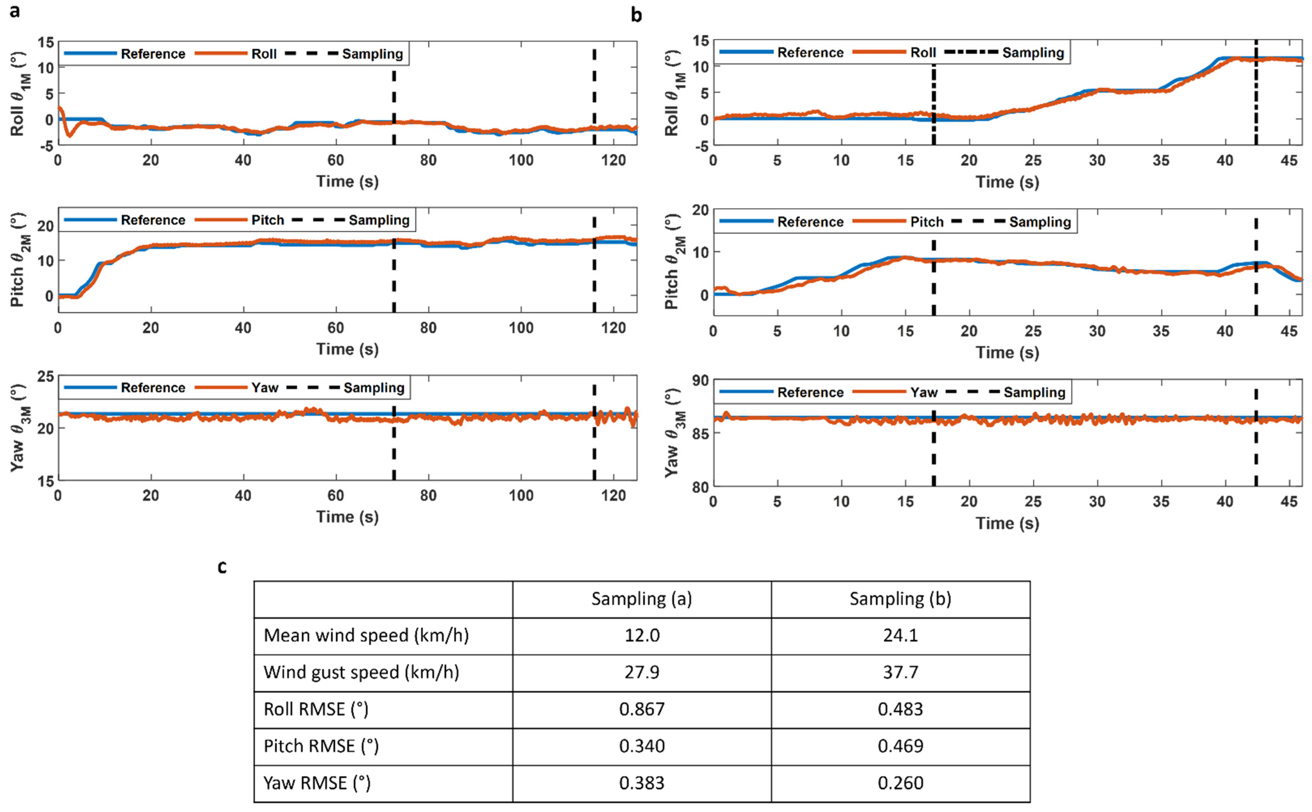
Sampled plants were in various environments like canyons, ravines, and sea cliffs all presenting vertical surfaces to sample from. In all environments, the wind represented one of the main challenges with average winds ranging from 3.4 to 31.6 km/h with gusts reaching more than 40 km/h on six distinct flights. Some of the tests were conducted in winds near the limit prescribed by DJI for the M300, which is 12 m/s (43.2 km/h), which appears to be the limitation of the current system. Despite the ability of the suspended manipulator and its carrier drone to maintain precise positioning under high wind conditions, the motion of the plants proved to be the challenge. However, it’s noteworthy that while this dynamic interaction added a level of complication, it remained manageable for the operator. The influence of wind on collection time was found to be relatively minor when compared to the diversity in plant morphology, showcasing the robustness of the suspended manipulator system in overcoming environmental challenges during plant sampling in windy conditions. Figure 11 shows the performance of the suspended manipulator control system in a real-world scenario during two sampling operations in Reunion Island. The flight out and back from the sampling area which may take up to 10 min is not shown in these graphs to put an emphasis on the sampling operation itself. Both flights show two sampling attempts during the collection of the targeted plant. The states estimated by the Kalman filter are noisier than during indoor tests, and this is explained by the external disturbances applied to the system, such as wind, the movement of the carrier drone and contact forces during the sampling phase of the flight. These two examples help to better understand the limited influence of wind on the flight performance of the Mamba. Despite much higher wind speeds during flight (b), the platform shows similar performance in maintaining its orientation as shown by the root mean square error of each flight in (c). Overall, the suspended platform demonstrates its ability to sustain high wind speed on sampling operations showcasing the ability of the tool to operate in real-world conditions.
Although the results in Figure 11 show the stability of the Mamba in presence of strong winds, it is also interesting to observe the robustness of the control system during field tests and tests carried out in the indoor flight room. Figure 12 compares the commands sent to the actuators during a static portion of the Mamba’s flight both for laboratory testing and an outdoor flight with winds of 11.1 km/h with gusts up to 21.1 km/h. For Figure 12c, the static component of the command to the actuators has been filtered out. Only the variations in the commands sent to the actuators for the roll and pitch axes are shown. We note that the variations in the commands sent to the actuators during a static portion of the laboratory tests are much smaller in amplitude compared to the external tests. The standard deviation is much greater during the outdoor sampling operation: 3.4 times greater for the roll axis, and 1.9 times greater on the pitch axis. This tends to demonstrate the effectiveness of the control system in the presence of external disturbances during sampling operations as the Mamba keeps its precise positioning.
5. Conclusions
Scientists working on biodiversity conservation in cliffs habitat use techniques at their disposal to collect parts of endangered plant species. The current techniques (e.g., abseiling, climbing) pose significant risks to their safety, not to mention that many habitats remain completely inaccessible. To overcome this problem, this study presents a suspended manipulator under a drone to collect plant samples on cliffs. This study makes new contributions to the field of aerial manipulators suspended under a lifting system by presenting an accurate dynamic model of the system as well as a model-based control system relying solely on an IMU for operation in GNSS-denied environments providing high positioning accuracy and bandwidth for a suspended manipulator. Indoor tests have demonstrated the high accuracy of the developed system while maintaining high stability and low orientation error over all the controlled degrees of freedom. Real-world testing of the system took place on the island of Kaua’i in the Hawaiian archipelago and in Reunion Island where the prototype was able to collect from many endemic and rare plants on three distinct field trips in winds higher than 40 km/h, while maintaining a precision error of less than 1 degree on all orientations during sampling operations.
The technology developed in this project has also demonstrated that it can have an immediate impact on the field of conservation. Over the course of those sampling campaigns, the Mamba allowed the collection of 55 samples from 28 species from which 19 are considered critically endangered and 3 were considered extinct in the wild. For example, the samples collected from a specimen of Plantago princeps enabled the NTBG to propagate this species in their nursery. Knowing that there are only 50 individuals of this species left, these encouraging results clearly show the usefulness of this suspended manipulator technology for conservation.
Future work includes training conservation scientists on the use of the Mamba to facilitate its use on a larger scale, and the development of new sampling mechanisms more suitable for collecting specific plant’s part in hard-to-reach environments. By retaining the same mechanical design for the main platform, the integration of new sampling mechanisms will be facilitated and will greatly help with the sampling of a more diverse plant morphology.
Author Contributions
H.L.V., G.C. and A.L.D. wrote the manuscript text. H.L.V., G.C. and A.L.D. prepared Figure 1, Figure 2, Figure 3, Figure 4, Figure 5, Figure 6, Figure 7, Figure 8, Figure 9, Figure 10, Figure 11 and Figure 12. H.L.V., G.C., D.R. and A.L.D. contributed to the research and edited the manuscript. All authors have read and agreed to the published version of the manuscript.
Funding
This study was funded by National Geographic (Grant # NGS-55048T-19, NGS-95753T-22), Investissement Quebec (Grant # SQRI51213), Vanier Canada Graduate Scholarships (Grant # 433895), CRSNG (Grant # 546877), the Mohamed bin Zayed Species Conservation Fund (Grant # 192521645), and Mitacs (Grant # IT18507, # IT18343).
Data Availability Statement
No datasets were generated or analyzed during the current study.
Acknowledgments
We acknowledge the strong commitment to plant conservation by staff at the National Tropical Botanical Garden, the Plant Extinction Prevention Program, the State of Hawai’i—Division of Forestry and Wildlife, and the Conservatoire Botanique National Mascarin. The collection of plant material complied with relevant institutional, national, and international guidelines and legislation, and the IUCN Policy Statement on Research Involving Species at Risk of Extinction and Convention on the Trade in Endangered Species of Wild Fauna and Flora. The plants were collected in close coordination with the State of Hawai’I staff under the Threatened and Endangered Species Permit (# I2499) and Forest Reserve Special Use Permit (#Kpi-2021-247). Voucher specimens of the plants collected have been deposited in a publicly available herbarium of the National Tropical Botanical Garden—PTBG (collector numbers: AMW 705, AMW 706, AMW 709, BN 006, BN 007, BN 011). Living material is growing at NTBG nursery (accession numbers: 20210566-2020572). David H. Lorence undertook the taxonomic review of these plant specimens.
Conflicts of Interest
H.L.V., G.C. and A.L.D. are affiliated with Outreach Robotics, which commercializes the DeLeaves tree sampling tool. D.R. declares no potential conflicts of interest.
References
- Nyberg, B. Eyes in the sky: Drones proving their value in plant conservation. BGjournal 2019, 16, 25–27. [Google Scholar]
- Wagner, W.L.; Weller, S.G.; Sakai, A.K. Description of a Rare New Cliff-Dwelling Species from Kaua’i, Schiedea attenuata (Caryophyllaceae). Novon 1994, 4, 187–190. [Google Scholar] [CrossRef]
- Lorence, D.H.; Wagner, W.L. Another New, Nearly Extinct Species of Hibiscadelphus (Malvaceae) from the Hawaiian Islands. Novon 1995, 5, 183–187. [Google Scholar] [CrossRef]
- Jordan, S.; Moore, J.; Hovet, S.; Box, J.; Perry, J.; Kirsche, K.; Lewis, D.; Tse, Z.T.H. State-of-the-art technologies for UAV inspections. IET Radar Sonar Navig. 2018, 12, 151–164. [Google Scholar] [CrossRef]
- Mandirola, M.; Casarotti, C.; Peloso, S.; Lanese, I.; Brunesi, E.; Senaldi, I. Use of UAS for damage inspection and assessment of bridge infrastructures. Int. J. Disaster Risk Reduct. 2022, 72, 102824. [Google Scholar] [CrossRef]
- Ecke, S.; Dempewolf, J.; Frey, J.; Schwaller, A.; Endres, E.; Klemmt, H.-J.; Tiede, D.; Seifert, T. UAV-Based Forest Health Monitoring: A Systematic Review. Remote Sens. 2022, 14, 3205. [Google Scholar] [CrossRef]
- Diez, Y.; Kentsch, S.; Fukuda, M.; Caceres, M.L.L.; Moritake, K.; Cabezas, M. Deep Learning in Forestry Using UAV-Acquired RGB Data: A Practical Review. Remote Sens. 2021, 13, 2837. [Google Scholar] [CrossRef]
- Messina, G.; Modica, G. Applications of UAV Thermal Imagery in Precision Agriculture: State of the Art and Future Research Outlook. Remote Sens. 2020, 12, 1491. [Google Scholar] [CrossRef]
- Tsouros, D.C.; Bibi, S.; Sarigiannidis, P.G. A Review on UAV-Based Applications for Precision Agriculture. Information 2019, 10, 349. [Google Scholar] [CrossRef]
- Ivanovic, A.; Markovic, L.; Car, M.; Duvnjak, I.; Orsag, M. Towards Autonomous Bridge Inspection: Sensor Mounting Using Aerial Manipulators. Appl. Sci. 2021, 11, 8279. [Google Scholar] [CrossRef]
- McArthur, D.R.; An, Z.; Cappelleri, D.J. Pose-Estimate-Based Target Tracking for Human-Guided Remote Sensor Mounting with a UAV. In Proceedings of the IEEE International Conference on Robotics and Automation (ICRA), Paris, France, 31 May–31 August 2020; pp. 10636–10642. [Google Scholar]
- Hamaza, S.; Georgilas, I.; Heredia, G.; Ollero, A.; Richardson, T. Design, modeling, and control of an aerial manipulator for placement and retrieval of sensors in the environment. J. Field Robot. 2020, 37, 1224–1245. [Google Scholar] [CrossRef]
- Ikeda, T.; Yasui, S.; Fujihara, M.; Ohara, K.; Ashizawa, S.; Ichikawa, A.; Okino, A.; Oomichi, T.; Fukuda, T. Wall contact by octo-rotor UAV with one DoF manipulator for bridge inspection. In Proceedings of the IEEE/RSJ International Conference on Intelligent Robots and Systems (IROS), Vancouver, BC, Canada, 24–28 September 2017; pp. 5122–5127. [Google Scholar]
- Ichikawa, A.; Abe, Y.; Ikeda, T.; Ohara, K.; Kishikawa, J.; Ashizawa, S.; Oomichi, T.; Okino, A.; Fukuda, T. UAV with manipulator for bridge inspection—Hammering system for mounting to UAV. In Proceedings of the IEEE/SICE International Symposium on System Integration (SII), Taipei, Taiwan, 11–14 December 2017; pp. 775–780. [Google Scholar]
- Jimenez-Cano, A.E.; Heredia, G.; Ollero, A. Aerial manipulator with a compliant arm for bridge inspection. In Proceedings of the International Conference on Unmanned Aircraft Systems (ICUAS), Miami, FL, USA, 13–16 June 2017; pp. 1217–1222. [Google Scholar]
- Ollero, A.; Cortes, J.; Santamaria-Navarro, A.; Trujillo Soto, M.A.; Balachandran, R.; Andrade-Cetto, J.; Rodriguez, A.; Heredia, G.; Franchi, A.; Antonelli, G.; et al. The AEROARMS Project: Aerial Robots with Advanced Manipulation Capabilities for Inspection and Maintenance. IEEE Robot. Automat. Mag. 2018, 25, 12–23. [Google Scholar] [CrossRef]
- Udell, C.; Kamel, M. An open drone payload interface for industrial NDT collaboration. In Proceedings of the NDE 4.0, Predictive Maintenance, and Communication and Energy Systems in a Globally Networked World, Long Beach, CA, USA, 6 March–11 April 2022; SPIE: Bellingham, WA, USA, 2022; Volume PC12049. [Google Scholar]
- Rodriguez-Castaño, A.; Nekoo, S.R.; Romero, H.; Salmoral, R.; Acosta, J.Á.; Ollero, A. Installation of Clip-Type Bird Flight Diverters on High-Voltage Power Lines with Aerial Manipulation Robot: Prototype and Testbed Experimentation. Appl. Sci. 2021, 11, 7427. [Google Scholar] [CrossRef]
- Kutia, J.R. Aerial Manipulation for Canopy Sampling. Ph.D. Thesis, University of Auckland, Auckland, New Zealand, 2019. [Google Scholar]
- Kim, S.; Seo, H.; Choi, S.; Kim, H.J. Vision-Guided Aerial Manipulation Using a Multirotor with a Robotic Arm. IEEE/ASME Trans. Mechatron. 2016, 21, 1912–1923. [Google Scholar] [CrossRef]
- Stephens, B.; Orr, L.; Kocer, B.B.; Nguyen, H.-N.; Kovac, M. An Aerial Parallel Manipulator with Shared Compliance. IEEE Robot. Autom. Lett. 2022, 7, 11902–11909. [Google Scholar] [CrossRef]
- Käslin, F.; Baur, T.; Meier, P.; Koller, P.; Buchmann, N.; D’Odorico, P.; Eugster, W. Novel Twig Sampling Method by Unmanned Aerial Vehicle (UAV). Front. For. Glob. Chang. 2018, 1, 2. [Google Scholar] [CrossRef]
- Charron, G.; Robichaud Courteau, T.; La Vigne, H.; Hill, A.; Justice, D.; Bélanger, N.; Lussier Desbiens, A.; Lussier Desbiens, A. The DeLeaves: A UAV device for efficient tree canopy sampling. J. Unmanned Veh. Syst. 2020, 8, 245–264. [Google Scholar] [CrossRef]
- Sarkisov, Y.S.; Kim, M.J.; Bicego, D.; Tsetserukou, D.; Ott, C.; Franchi, A.; Kondak, K. Development of SAM: Cable-Suspended Aerial Manipulator. arXiv 2019, arXiv:1903.02426. [Google Scholar]
- Miyazaki, R.; Jiang, R.; Paul, H.; Huang, Y.; Shimonomura, K. Long-Reach Aerial Manipulation Employing Wire-Suspended Hand with Swing-Suppression Device. IEEE Robot. Autom. Lett. 2019, 4, 3045–3052. [Google Scholar] [CrossRef]
- Miyazaki, R.; Paul, H.; Kominami, T.; Shimonomura, K. Wire-Suspended Device Control Based on Wireless Communication with Multirotor for Long Reach-Aerial Manipulation. IEEE Access 2020, 8, 172096–172104. [Google Scholar] [CrossRef]
- Sarkisov, Y.S.; Kim, M.J.; Coelho, A.; Tsetserukou, D.; Ott, C.; Kondak, K. Optimal Oscillation Damping Control of cable-Suspended Aerial Manipulator with a Single IMU Sensor. arXiv 2020, arXiv:2003.00472. [Google Scholar]
- La Vigne, H.; Charron, G.; Rachiele-Tremblay, J.; Rancourt, D.; Nyberg, B.; Lussier Desbiens, A. Collecting critically endangered cliff plants using a drone-based sampling manipulator. Sci. Rep. 2022, 12, 14827. [Google Scholar] [CrossRef] [PubMed]
- La Vigne, H.; Charron, G.; Tremblay, J.R.; Nyberg, B.; Desbiens, A.L. Preliminary design of an aerial cliff sampling system. In Proceedings of the 2021 Aerial Robotic Systems Physically Interacting with the Environment (AIRPHARO), Biograd na Moru, Croatia, 4–5 October 2021; pp. 1–4. [Google Scholar]
- Rachiele-Tremblay, J.; Vigne, H.L.; Charron, G.; Rancourt, D.; Lussier-Desbiens, A. Experimental Performance Comparison of Bidirectional Actuator Configurations for Suspended Aerial Platforms. IEEE Robot. Autom. Lett. 2022, 7, 11601–11608. [Google Scholar] [CrossRef]
- ArduPilot. Available online: https://ardupilot.org (accessed on 10 January 2024).
- Mitiguy, P. Advanced Dynamics and Motion Simulation; Prodigy Press: Sunnyvale, CA, USA, 2014. [Google Scholar]
- Premerlani, W.; Bizard, P. Direction Cosine Matrix IMU: Theory. Diy Drone USA 2009, 1. Available online: https://www.researchgate.net/publication/265755808 (accessed on 13 December 2023).
- Groves, P. Principles of GNSS, Inertial, and Multisensor Integrated Navigation Systems, 2nd ed.; Artech: Norwood, MA, USA, 2013. [Google Scholar]
- Matrice 300 RTK—Built Tough. Works Smart. Available online: https://enterprise.dji.com/matrice-300 (accessed on 10 December 2023).
Figure 1.
A schematic view of the Mamba suspended under a drone.

Figure 2.
(a) Side view of the Mamba showing the components and the suspending cables. (b) Top view of the Mamba showing the thrusts generated by the actuators. (c) Close-up of the sampling tool and 2-DOF wrist specifically designed to sample plants.
Figure 2.
(a) Side view of the Mamba showing the components and the suspending cables. (b) Top view of the Mamba showing the thrusts generated by the actuators. (c) Close-up of the sampling tool and 2-DOF wrist specifically designed to sample plants.

Figure 3.
Diagrams of the component used on the Mamba.

Figure 4.
Physical model of the suspended manipulator.

Figure 5.
System response to doublet inputs in both the roll and pitch orientation.

Figure 6.
The Mamba control system and state estimator diagram.

Figure 7.
(a) Consecutive step inputs applied to the model in simulation to validate the performance of the control system on the roll and pitch orientation. (b) Close up of the first step input for the roll and pitch orientation of the Mamba.
Figure 7.
(a) Consecutive step inputs applied to the model in simulation to validate the performance of the control system on the roll and pitch orientation. (b) Close up of the first step input for the roll and pitch orientation of the Mamba.

Figure 8.
(a) Comparison of the model simulation, the motion capture system, and the flight controller data for consecutive step inputs applied separately on the roll and pitch axes. (b) Detailed comparison of the first step input on the roll and pitch axes.
Figure 8.
(a) Comparison of the model simulation, the motion capture system, and the flight controller data for consecutive step inputs applied separately on the roll and pitch axes. (b) Detailed comparison of the first step input on the roll and pitch axes.

Figure 9.
(a) Comparison of the model simulation, the motion capture system, and the flight controller data for consecutive step inputs applied simultaneously on the roll and pitch axes to simulate a sampling operation. (b) Detailed comparison of the simultaneous first step inputs on the roll and pitch axes.

Figure 10.
(a) Mamba collecting a sample from a Kadua st-johnii plant in Hawai’i with stems that are less than 15 cm. (b) Collection of a Wilkesia hobdyi flower in Hawai’i. This shrub has branches up to 60 cm long. (c) Mamba collecting a sample from a Foetidia mauritiana tree in Reunion Island. A tree that can reach a height of 20 m. (d) Collection of Terminalia bentzoe fruits in Reunion Island. A tree that can reach a height of 30 m. All the images on the right side depict samples collected using the Mamba.

Figure 11.
(a) Orientation of the Mamba during a sampling operation with a mean wind speed of 12.0 km/h and wind gusts reaching 24.1 km/h. (b) Orientation of the Mamba during a sampling operation with a mean wind speed of 27.9 km/h and wind gusts reaching 37.7 km/h. (c) Comparison of the root mean square error for each axis during the sampling operation for (a), and (b) flight.

Figure 12.
(a) Orientation of the Mamba during a sampling operation with a mean wind speed of 11.1 km/h and wind gusts reaching 21.1 km/h. (b) Orientation of the Mamba during an indoor step test. (c) Comparison of the actuator thrust command for the roll and pitch axes during a static portion of the sampling operation (a), and the step test (b) for 8 s with the static component of the command filtered out.


Table 1.
Model parameters for the indoor flight room validations.
| Parameters | Value |
|---|---|
| L1 | 4.1 m |
| L2 | 1.65 m |
| L3 | 0.04 m |
| L4 | 0.02 m |
| Ixx | 0.12 kg m2 |
| Iyy | 0.65 kg m2 |
| Izz | 0.61 kg m2 |
| mP | 3.02 kg |
| mM | 0.03 kg |
Disclaimer/Publisher’s Note: The statements, opinions and data contained in all publications are solely those of the individual author(s) and contributor(s) and not of MDPI and/or the editor(s). MDPI and/or the editor(s) disclaim responsibility for any injury to people or property resulting from any ideas, methods, instructions or products referred to in the content. |
© 2024 by the authors. Licensee MDPI, Basel, Switzerland. This article is an open access article distributed under the terms and conditions of the Creative Commons Attribution (CC BY) license (https://creativecommons.org/licenses/by/4.0/).
Share and Cite
MDPI and ACS Style
La Vigne, H.; Charron, G.; Rancourt, D.; Lussier Desbiens, A. The Mamba: A Suspended Manipulator to Sample Plants in Cliff Environments. Drones 2024, 8, 139. https://doi.org/10.3390/drones8040139
AMA Style
La Vigne H, Charron G, Rancourt D, Lussier Desbiens A. The Mamba: A Suspended Manipulator to Sample Plants in Cliff Environments. Drones. 2024; 8(4):139. https://doi.org/10.3390/drones8040139
Chicago/Turabian StyleLa Vigne, Hughes, Guillaume Charron, David Rancourt, and Alexis Lussier Desbiens. 2024. "The Mamba: A Suspended Manipulator to Sample Plants in Cliff Environments" Drones 8, no. 4: 139. https://doi.org/10.3390/drones8040139