

Surrogate Optimal Fractional Control for Constrained Operational Service of UAV Systems
by
 , , , and
Mohammed Moness
1,*,
Muhammad Bakr Abdelghany
1,2,
Khloud Mostafa Mohammed
1,
Moataz Mohamed
3 and
Ahmed M. Moustafa
1 1
Computers and Systems Engineering Department, Faculty of Engineering, Minia University, Minia 61519, Egypt
2
Advanced Power and Energy Center, EECS Department, Khalifa University of Science and Technology, Abu Dhabi 127788, United Arab Emirates
3
McMaster Institute for Transportation and Logistics, McMaster University, 1280 Main Street West, Hamilton, ON L8S 4K1, Canada
*
Author to whom correspondence should be addressed.
Drones 2024, 8(4), 141; https://doi.org/10.3390/drones8040141
Submission received: 20 February 2024
/
Revised: 21 March 2024
/
Accepted: 1 April 2024
/
Published: 3 April 2024
Abstract
:In the expeditiously evolving discipline of autonomous aerial robotics, the efficiency and precision of drone control deliveries have become predominant. Different control strategies for UAV systems have been thoroughly investigated, yet PID controllers still receive significant consideration at various levels in the control loop. Although fractional-order PID controllers (FOPID) have greater flexibility than integer-order PID (IOPID) controllers, they are approached with caution and hesitance. This is due to the fact that FOPID controllers are more computationally intensive to tune, as well as being more challenging to implement accurately in real time. In this paper, we address this problem by developing and implementing a surrogate-based analysis and optimization (SBAO) of a relatively high-order approximation of FOPID controllers. The proposed approach was verified through two case studies; a simulation quadrotor benchmark model for waypoint navigation, and a real-time twin-rotor copter system. The obtained results validated and favored the SBAO approach over other classical heuristic methods for IOPID and FOPID.
1. Motivation and Introduction
Urban emissions rates are soaring, and the transportation sector has formed a substantial 40% of the global greenhouse gas output over the last 20 years [1]. As such, recent years have seen a remarkable surge in the adoption of alternative energy sources within the transportation domain, a trend that is expected to endure [2]. Coupled with the advancement of e-commerce and the demand for same-day delivery, unmanned aerial vehicles (UAVs) are considered a major player in urban logistics. UAVs seamlessly integrate electric mobility with autonomy, offering near-carbon-free, speedy, and economic solutions. UAVs signify a revolutionary paradigm shift in transportation, issuing a resounding call to surpass traditional modes. While electric vehicles progressively carve out their niche, UAVs propel us into boundless skies, epitomizing the fusion of sustainability and precision engineering. In this dynamic landscape, the multi-rotor system, distinguished by its intricate architecture, has garnered significant attention due to its multifaceted real-time applications, playing a pivotal role in advancing real-time control within transportation systems [3].
The system’s complex dynamics present both challenges and opportunities, making it an ideal platform for refining cutting-edge control methodologies. As industries increasingly demand real-time control solutions, a comprehensive understanding of UAV dynamics and their applicability is pivotal in advancing control theory and practical implementation, particularly in the transportation domain [4]. Furthermore, multiple-rotor systems exhibit enhanced stability and autonomous operation. This autonomy significantly reduces the need for direct human-operator control. Furthermore, these systems serve as exceptional platforms for research and commercial ventures, boasting remarkable technological capabilities.
In contrast to conventional UAVs, aerial robot manipulators such as quadrotors and twin rotors present distinct kinematic architectures. For instance, a quadrotor employs a unique configuration with two rods and four actuators, achieving torque equilibrium by coordinating two rotors to rotate clockwise and the remaining two to rotate counterclockwise [5]. Similarly, a twin-rotor design operates on a comparable principle. In this setup, a substantially interconnected propeller, controlled by the main rotor, assumes the responsibility for stabilizing the platform’s vertical orientation, effectively counteracting angular deviations along the vertical axis. Simultaneously, a smaller propeller, maneuvered by the tail rotor, enables precise adjustments along the horizontal axis [6,7]. The dynamic interplay of these configurations, whether quadrotor or twin-rotor, is regulated by intricate adjustments in pitch and yaw angles. It is important to highlight that the main value of these configurations lies in their comprehensive evaluation of complex control algorithms, leveraging their inherent cross-coupling dynamics and nonlinear structural characteristics.
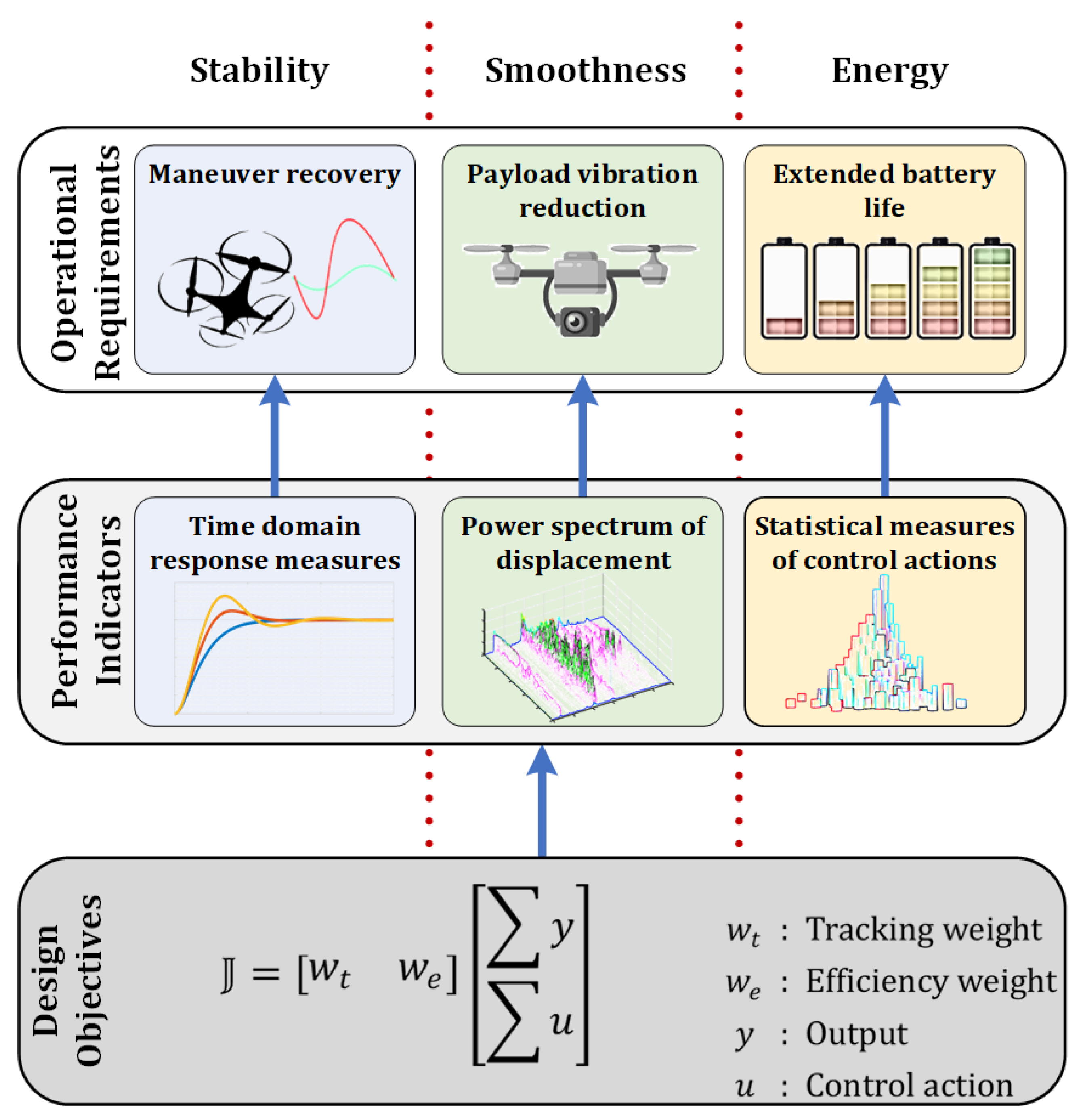
Novel methods are being developed to meet the diverse demands of multi-objective flight control systems for flexible aircraft. Several research groups have studied and performed original research in drone guidance, navigation, and control [8]. However, deployment of UAVs has encountered a variety of constraints within different service levels, as characterized by the matrix map in Figure 1. The core achievement of a UAV mission begins with executing operational commands, while meeting technical constraints. A typical scenario that illustrates this argument is to follow a predetermined trajectory with stable, smooth, and energy-efficient performance constraints. Accordingly, this work considers an integrated approach that combines a flexible control structure, a design criterion, and a global optimization method. The control structure applied here is an FOPID controller that achieves a sophisticated and flexible response function shape through five parameters.This control structure with the corresponding design criterion produces a non-convex and computationally intensive optimization problem that requires global and efficient techniques to solve. This work investigates the applicability of surrogate-based optimization as a potential solver. The optimal design criteria include a set of operational requirements related to stability, smoothness, and energy that can be assessed through different performance indicators, as shown in Figure 2.
1.1. Key Contributions
This paper extends the current research on PID control of UAV systems by focusing on FOPID controllers of multivariable cross-coupled dynamics. It also targets the efficiency of the design process for FOPID controllers through surrogate models. The contributions are summarized in the following points:
- This work investigates and evaluates the applicability and the inherent flexibility of FOC for UAV systems. The obtained findings should support the seamless integration of surrogate FOC design within UAV controllers for transport applications.
- A FOPID is more time-consuming and computationally intensive than integer-order PID. Therefore, this work studies and analyzes surrogate modeling and optimization for such an expensive function.
- The investigated surrogate-based FOPID was verified in a simulation with a benchmark waypoint navigation quadrotor model. In addition, it was verified for a real-time twin-rotor copter system, to investigate its real-time performance.
1.2. Outline
The remainder of the paper is structured as follows: Section 2 reviews the current research in the modeling and control of UAVs with the corresponding relevant optimization techniques. Fractional-order controllers are discussed and derived in Section 3. Section 4 describes and develops the mathematical models for the UAV benchmarks. The surrogate optimization is explained and investigated in Section 5. The results showing the effectiveness of the proposed controller are presented in Section 6. Section 7 concludes the paper.
2. Literature Review
2.1. Modeling and Control of UAVs
In pursuit of achieving robust tracking performance within nonlinear simulations involving aggressive maneuvers under dynamic and uncertain conditions, a common control approach is the utilization of proportional-integral-derivative (PID) control. This method is the most widely adopted controller across a spectrum of application domains, primarily due to its inherent simplicity of structure and ease of implementation [9,10]. With respect to PID control for a quadrotor system, as reported in [11,12,13], a control strategy has been developed for a quadrotor system based on a PD algorithm, to achieve stability and precise control over the position of quadrotors, even in the presence of disturbances. Furthermore, in [14], the PD controller method was integrated to ensure the stability of the Newton–Euler angles and the altitude of the quadcopter system. The authors in [15] designed a PD controller for a micro-UAV to control the rotational angles and maintain the attitude stability of the quadrotor system on a flying platform. Moreover, the authors in [16] extensively explained a dynamic model of a quadrotor and implemented a PD control algorithm to regulate the orientation and track the trajectory of the quadrotor. A sophisticated approach based on a self-tuning fuzzy PID controller paired with an extended Kalman filter was developed for the precise posture control of a quadcopter in [17]. Moreover, the authors in [18] integrated a fuzzy neural network PID control to determine the aerodynamic environment of the blade. Regarding PID for twin-rotor systems, for example, the authors in [19] developed an optimal auto-tuned PID controller for a twin-rotor MIMO system through a RAO-1 optimization algorithm. In [20], a PID controller based on PSO of a twin-rotor was used to stabilize the proposed system. A nonlinear PID controller using a chaotic gravitational search algorithm for a twin-rotor system was proposed in [21]. However, the strategies mentioned above only focused on PID controllers for UAV systems considering either raw PID or combined with neural networks or fuzzy logic rules. They did not take into account the inherent complexity of the tuning process or the flexibility of wider versions of PID utilizing fractional-order phenomena.
Fractional-order control (FOC) constitutes a specialized branch within mathematics, primarily concerned with analyzing systems characterized by derivatives or integrals of non-integer orders [22,23]. This domain considers integer-order models as a distinct subspace. The classical fractional-order derivatives are recognized for their inherent memory-dependent attributes. The integration of these features with an additional tunable parameter introduced in the novel fractional-order framework has garnered considerable attention from the research community [24]. This has resulted in the widespread utilization of fractional-order models across a spectrum of engineering disciplines [25]. However, the application of fractional-order models to control system scenarios encounters a challenge. The theoretical properties of infinite memory and bandwidth associated with these models are infeasible to achieve in practice. Consequently, recent studies have revealed that FOC has the ability to improve the dynamic performance of UAVs. For instance, the authors in [26] developed a data-driven FOC for UAVs, to enable precise trajectory tracking despite external disturbances and uncertainties. In order to mitigate disturbance, a FOC-extended state observer of a Tri-copter UAV was developed in [27]. Furthermore, an adaptive FOC-sliding mode formation control of a multiple quadrotor UAV-based distributed estimator was developed in [28]. The authors in [29] proposed a robust formation tracking problem for a heterogeneous multi-robot system with FOC, consisting of UAVs and unmanned surface vehicles (USVs), to handle multiple disturbances. In [30], a refined fault-tolerant tracking control of fixed-wing UAVs based on FOC paired with an interval type-2 fuzzy neural network under event-triggered communication was developed to decrease communication overloads. The authors in [31] proposed a robust discrete-time FOC for UAV systems using the backstepping control technique to guarantee the stability of the closed-loop system. In further examples, the authors in [32] designed an event-triggered FOC with sliding mode control quadrotor UAVs to ensure the altitude and position tracking of the desired dynamics. However, literature regarding the application of FOCs with surrogate-based analysis and optimization (SBAO) for UAVs is quite scarce.
2.2. Optimization Techniques
Heuristics and meta-heuristics techniques have also been proposed in the literature. In particular, the genetic algorithm, the particle swarm optimization, the duelist algorithm, the simulated annealing, the ant colony optimization, and the Manta-ray foraging optimizer are examples of meta-heuristic algorithms [5]. Furthermore, the acquisition of analytical solutions for problems involving fractional orders is not universally feasible, due to the intricate nature of the associated mathematical expressions. Consequently, there has been a noticeable increase in the inclination toward applying meta-heuristic optimization techniques within the realm of fractional calculus literature. The tuning of control parameters has many economic advantages, which have been investigated in the literature. From a chronological perspective, one of the earliest contributions to this field pertained to applying the differential evolution algorithm to design an FO-PID characterized by a specific response [33]. In [34], the incorporation of a FOPID system for coordinating multiple UAVs, facilitated by particle swarm optimization (PSO), was coordinated to yield an optimal methodology for global path planning through meticulous validation conducted via virtual simulations. Moreover, the surrogate-based analysis and optimization (SBAO) approach has been a successful optimizer for the design of computationally complex models, such as those found in aerospace systems, which involve a variety of disciplines, including aerodynamics, structures, and propulsion. For example, the authors in [35] evaluated SBAO for robot swarm simulations. Furthermore, in [36], an optimization of the UAV inspection approach for infrastructure based on the SBAO framework was developed. The authors in [37] introduced an SBAO based on gene expression programming, leading to an enhanced optimal design with reduced computational expenditure. In [38], the authors presented an SBAO based on the Kriging technique to optimize the delta and canard wing design for a tube-fan hybrid UAV. Despite being proposed in the literature for enhancing UAV stability and tracking, the optimization of controllers with contemporary methods remains a challenge for achieving improved responses in the presence of disturbances and uncertainty.
The PID parameter tuning problem is considered an NP-hard problem requiring heuristic and global optimization techniques [9]. The PID optimization usually involves running a simulation and computing a performance index that reflects the optimality of the designed controller regarding target requirements. In such cases, heuristic optimization algorithms such as GA and swarm intelligence may not be a very efficient choice, as they can be computationally intensive due to considerable evaluation of the expensive objective function [39]. Therefore, surrogate optimization is envisioned as a promising method for the optimization and exploration of system design [40]. Generally speaking, surrogate modeling is a set of mathematical techniques that are applied to build a model of black-box-engineered systems for which obtaining a measured output is very costly. In particular, surrogate optimization searches for a global optimal point through a compendious approximation of a computationally intensive objective function. The constructed surrogate models should have well-formed characteristics such as polynomial functions, radial basis functions (RBF), Kriging models, and support vector regressions [41]. Surrogate optimization has received significant research consideration for various applications, such as desalination microgrids [42], multi-generation energy system [43], resource allocation and network routing [44], electromagnetic [45], infrastructure of electric bus charging [46], and distribution network delivery time [47]. A fractional PID controller is challenging compared to a classical PID controller. Moreover, to our knowledge, FOPID control paired with entire UAVs with SBAO under FOC has not yet been analyzed.
Based on the literature discussed above, two main findings become apparent. On one hand, a continuous line of research exists to augment the stability of UAVs. Conversely, the application of FOC has exhibited improved dynamic responses within UAVs. Nevertheless, as per our current understanding, no studies have explored the impact of FOC on stability, nor its potential to enhance stability through a novel approach called SBAO. This void in knowledge propelled authors to incorporate principles from fractional calculus, leveraging surrogate-based analysis and optimization techniques, to expand the stable operating range of UAV systems. Accordingly, a variety of control algorithms and architectures have been developed and investigated for quadrotor UAV systems [48,49]. Nevertheless, PID still has considerable significance for the stabilization and control of inner loops of the UAV systems. PID comprises an optimal combination of simplicity, ease of implementation, and acceptable performance. Therefore, this paper investigated the tuning and behavior of a FOPID controller for operational tasks of subclass multi-rotor UAVs.
3. Fractional-Order Controllers
Fractional-order (FO) calculus constitutes a distinct mathematical discipline primarily concerned with examining and analyzing system models that feature derivatives or integrals characterized by non-integer orders. This field encompasses models with integer orders, forming a particular subset. Distinguished by their distinctive property of memory-dependent operation, classical FO derivatives have garnered substantial attention from the research community. Coupled with the additional tunability conferred by the emergent FO parameter, this characteristic has catalyzed the widespread adoption of FO models across various engineering domains. Their ability to capture intricate system dynamics has been recognized, contributing to the refinement of modeling precision and facilitating the comprehensive analysis of complex engineering systems. Nonetheless, achieving infinite memory and infinite bandwidth properties remains unfeasible in control system applications [50]. In addition, the increased complexity of the tuning process and approximation methods affects implementation accuracy. Moreover, FOPID parameters are non-intuitive to interpret compared to IOPID. This makes the fine manual tuning of the controllers harder and more difficult to understand. The three primary definitions frequently employed for FO derivative are Grünwald–Letnikov, Riemann–Liouville, and Caputo [51].
3.1. Realization of Fractional-Order Controllers
The mathematical definitions of the FO derivative do not have considerable significance from a practical point of view. Consequently, the pursuit involves finding a suitable approximation that mirrors certain attributes of the FO operator. FO integrator approximations serve as a pragmatic foundation for investigating real-world FO control implementations. They also facilitate the utilization of established and widely accepted techniques for assessing system stability. A significant number of these approximations take the form of band-limited integer-order transfer functions, emulating the magnitude and phase responses of within the specified frequency range. Instances of these approximations involve recognized methodologies, such as the Matsuda approach [52], the Trigeassou approach [53], and the Oustaloup technique [54] which is applied in this paper. This method transforms complex FO operators into integer-order systems, while retaining essential FO behavior for a certain frequency band. It facilitates practical engineering applications by enabling the use of established integer-order control techniques for analyzing and designing fractional-order systems. The Oustaloup approximation is defined for a fractional order operator as an integer-order transfer function with order in a frequency range of as [55]
where can be expressed as
The Oustaloup approximation is realized for digital control realization by applying a convenient emulation technique. An alternative realization method is to apply direct discrete conversion methods [56]. The embedded implementation of FO controllers would require more extensive design considerations to account for the related computational resources of the corresponding hardware and software [57].Therefore, the wide deployment of FO models and controllers motivates efficient microcontroller implementation for fractional calculus algorithms with a suitable set of optimization architecture-dependent techniques [58]. Generally speaking, FO controllers provide improved control performance, with a higher computational cost [59]. Some hardware-in-the-loop experiments for small UAV systems have shown that FO controllers exhibit similar CPU utilization as integer-order controllers, with a significantly higher usage of memory [60].
In order to address these computational and real-time implementation challenges, the challenges associated with FOPID controllers are addressed through a two-stage process that focuses on both computational and real-time implementation issues:
- Offline computational effort: The optimization objective function is computationally intensive. This problem is targeted through surrogate-based optimization, to obtain a surrogate model of the objective function for more efficient evaluations.
- Real-time implementation of the FOPID controller: The controller is approximated with the Oustaloup technique for suitable orders and frequency bands. Then, the obtained integer-order controller transfer function is discretized and emulated for digital control implementation. The approximation order can be selected as a trade-off between accuracy and real-time performance. The resulting integer order can be further reduced using a balanced reduction method. However, the available hardware was able to handle the calculated integer-order approximation without reduction.
Simultaneously, these approaches constitute a comprehensive response to the inherent challenges of FOPID controllers, facilitating their more efficient and practical application in control systems.
3.2. Fractional-Order PID Controller
FOPID controllers hold significant importance in the field of control engineering, due to their capacity to extend control capabilities to systems characterized by non-integer-order dynamics. These controllers offer distinct advantages compared to conventional PID controllers. Primarily, they excel in enhancing control performance, adapting to complex and dynamic systems, and allowing precise fine-tuning for specialized applications, particularly in scenarios involving fractional-order systems. Fractional-order control theory was introduced by Oustaloup [61]. The most well-established type of FO controller is the FOPID, which was developed by Podlubny [62] and that has the well-known form of [63]:
where , , and are the PID gains, and are the fractional operator coefficients. The integer-order PID is a special case of the general form in Equation (3), where . Figure 3 plots the different frequency responses for a set of PID with unity gains and different fractional coefficients. It is paramount to emphasize that the primary advantages of FOPID controllers over traditional PID controllers include the mitigation of oscillations, the reduction in overshoot, and the enhancement in control over dynamic and intricate system behaviors [64]. Nonetheless, it is imperative to acknowledge that their utilization also entails specific challenges, including the complexity of tuning due to the introduction of fractional orders and the inherent intricacy of their practical implementation [65]. Consequently, FOPID controllers represent a valuable instrument in control engineering, yet their effective deployment necessitates a profound understanding of the underlying system dynamics and meticulous attention being given to the intricacies of tuning and implementation. Although heuristic optimization algorithms could provide a straightforward solution for designing FO controllers [59], they might be very time-consuming, with a computational burden that is proportional to the complexity of the simulation time and integer-order approximation accuracy. Therefore, this paper considers surrogate modeling and optimization for such an expensive objective function in the context of UAV systems.
4. Mathematical Models for UAV Case Studies
Two aerial systems were considered to investigate the surrogate FOPID control. A simulation quadrotor benchmark model was employed to comparatively analyze the surrogate FOPID control against other recognized optimal controllers. In addition, a physical twin-rotor copter system was utilized to evaluate the real-time feasibility and performance of the surrogate FOPID through 2-DoF orientation control. In this section, the mathematical models for both aerial systems are outlined.
4.1. Quadrotor Benchmark Model
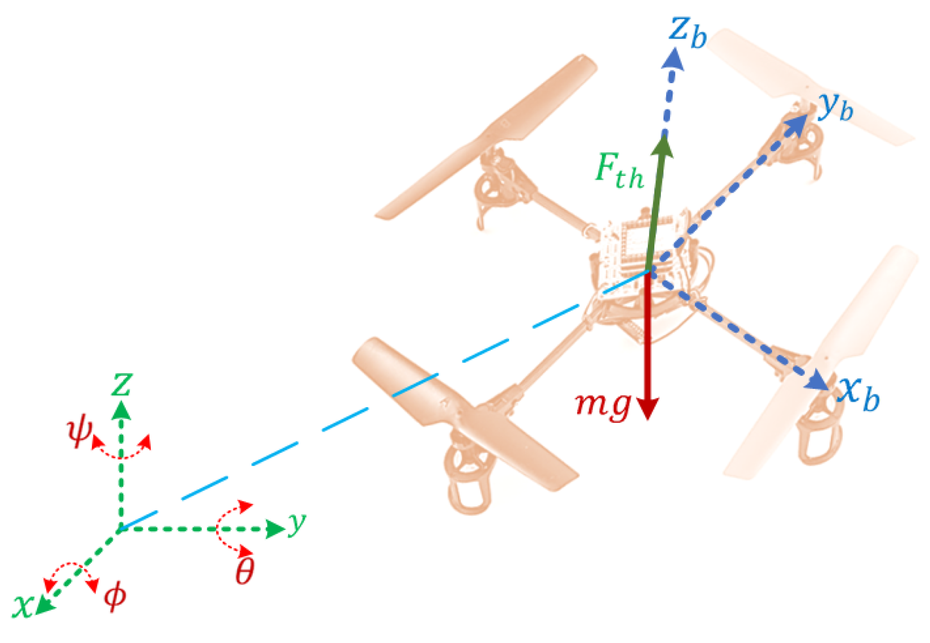
A guidance abstract model for a 1 kg quadrotor UAV was utilized to investigate the tuning of the FOPID using surrogate optimization. The model was a scaled version of the quadrotor described in detail in [5]. The kinematic model was acquired from the model developed in [66] and was implemented in the MATLAB UAV toolbox [67], incorporating a linear dynamical model controlled by orientation and thrust hold autopilot. The notations and conventions for quadrotor modeling, available in [5,66], are given in this subsection. The quadrotor used two frames: the earth frame and the body frame . These two frames are depicted in Figure 4. The orientation was defined as Euler angles for the yaw, pitch, and roll, respectively.
The earth and body frames were interrelated using a rotation matrix that was defined as follows:
where and denote and , respectively. The translational acceleration of the quadrotor point mass is defined as:
where m is the quadrotor mass, g is the gravitational acceleration constant, and is the total thrust force generated by the four rotors. The thrust subsystem in the navigation model used a first-order differential equation:
where is the thrust force command reference and is the thrust proportional constant. The angular acceleration is governed by
where p, q, and r are the body angular rates, , , and denote , and , respectively. The body angular rates are controlled through low-level inner feedback loops with PD controllers for the pitch and roll rotational motion and P controller for the yaw motion, as follows:
The quadrotor model parameters are presented in Table 1.
4.2. FOPID Waypoint Navigation Controller for the Quadrotor Benchmark
The navigation control loop was built around the control autopilot feedback loops for orientation motion and thrust control. The quadrotor earth position coordinates x, y, z were controlled by three decoupled FOPID controllers for each channel. The control signal vector is shown in Figure 5 and is defined as
where , and are the controller gains; and , , and are the control actions for pitch angle, roll angle, and thrust command, respectively. The is the position error and are the FOPID for coordinate x. The corresponding parameters are similarly defined for position coordinates y and z. As the position channels were assumed to be linearly decoupled, each FOPID controller could be tuned separately.
4.3. Twin-Rotor Copter System Model
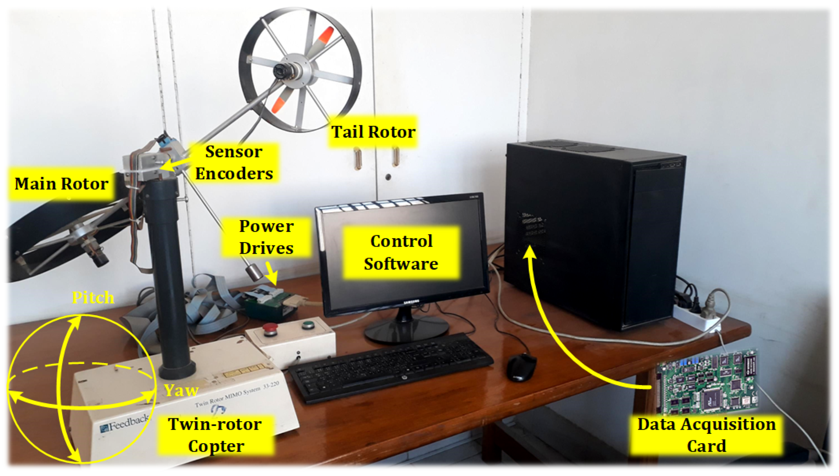
The twin-rotor copter system was an experimental benchmark device that is employed to evaluate multivariable control algorithms. The system was a twin-rotor powered beam with a counterbalance that could perform pitching and yawing maneuvers in 2-DoF motion [68]. It was controlled through a real-time computer system that was interfaced with a data acquisition card. Despite the considerable simplification, the twin-rotor copter had a significant resemblance to the real one with respect to nonlinearities and the high cross-coupling between pitch and yaw motions [7]. Figure 6 shows a block diagram of the twin-rotor copter system. Different modeling strategies were investigated for the twin-rotor copter system as in [6,69]. This paper adopted the linear model extracted in [70] for black box system identification with a sampling time of 0.1 s.
where m and t denote the main and tail inputs, respectively. is the pitch angle, while is the yaw angle.
4.4. Twin-Rotor Copter Real-Time Control Configuration
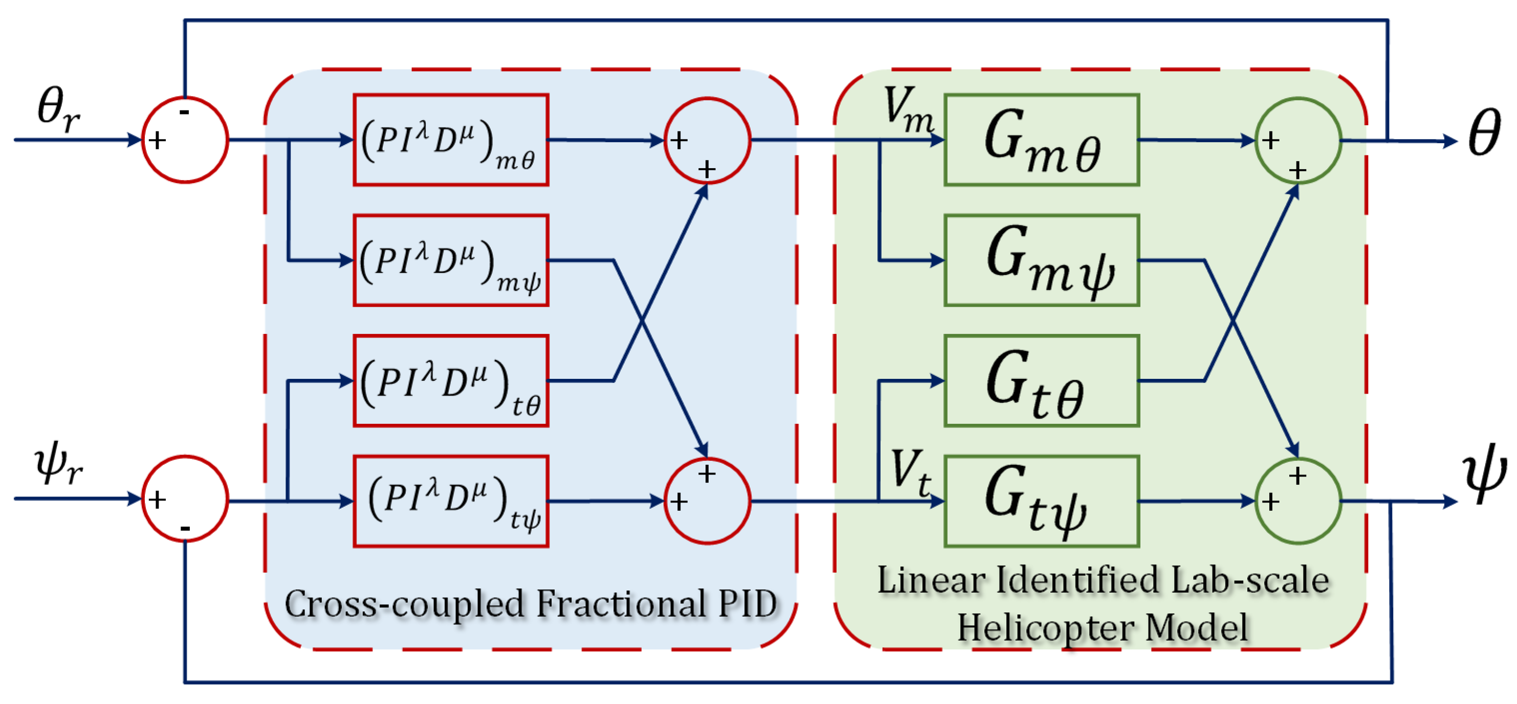
The twin-rotor copter system was controlled using four cross-coupled FOPID controllers, as depicted in Figure 7. The straight channels were decoupled and tuned first for the two forward FOPID controllers, in order to track the reference command signals. Then, the cross FOPID controllers were tuned to eliminate the cross-coupling effect. The controller matrix is stated as
where and are the main and the tail command voltages, respectively. The controller defined in (11) was converted with Oustaloup approximation and then discretized with a sampling time of s. The approximation was applied for an empirical range of frequencies rad/s that reflected the frequency range for the dynamics of the twin-rotor copter.
4.5. Problem Formulation of the FOPID Controller Parameter Optimization
The FOPID controller tuning problem involved minimizing a performance index. The performance index was a weighted sum of an integral squared error of the output variable and squared control action to ensure efficiency and limit controller aggressiveness. The performance index is defined as
where is the simulation time, is the controlled variable error, is the control action, is the maximum control actions, , and are relative weights to represent the design choice between the required performance and efficiency. The FOPID controller tuning can be formulated as
where is the FOPID controller parameters tuple as decision variables. The controller tuning optimization problem involved running a simulation to compute the performance index. This problem mostly generated a non-convex objective function, making the optimization problem NP-hard [9]. Therefore, a global or a heuristic optimization algorithm was obligatory for such a problem. The optimization criteria targeted the following objectives:
- The trajectory tracking: This requirement was incorporated into the objective function as an integral squared error.
- Energy utilization was inserted as a squared normalized control action to penalize large actions.
To give priority to energy efficiency, an equally weighted ratio was utilized.
4.6. Stability Analysis of the FOPID Controller
A linear model of the quadrotor pitch angle command for x displacement was extracted as
where the parameters in the above-mentioned formal can be defined as , , and , respectively. Consequently, the closed-loop transfer function for the x channel is computed as
According to the algorithm of stabilization of fractional-order systems developed in [71], the stability region is characterized by three root boundary curves:
- Real root boundary (RRB) represents the case where the real root crosses the imaginary axis at the origin. For the closed-loop system defined in (15), the RRB is .
- Infinite root boundary (IRB) defines the crossing of the real root of the imaginary axis at infinity.
- Complex root boundary (CRB) is characterized by the crossing of the real parts of a complex pair over the imaginary axis. The CRB curves were obtained using the following system of equations:
The parametric frequency polynomials in the CRB curve system of the equations are defined as follows:
The CRB curves are solved simultaneously for a given value of as
A set of samples for the stability regions in – plane for selected values of and are plotted in Figure 8. These curves can be augmented in the optimization formulation in Equation (13) as additional constraints. However, this would complicate the optimization problem. Hence, Equations (19a) and (19b) were assigned as post-check conditions to ensure stability. A more practical condition was to use the Oustaloup integer-order approximation for the FOPID and obtain the closed-loop representation to perform a linear integer-order stability test.
5. Surrogate Optimization
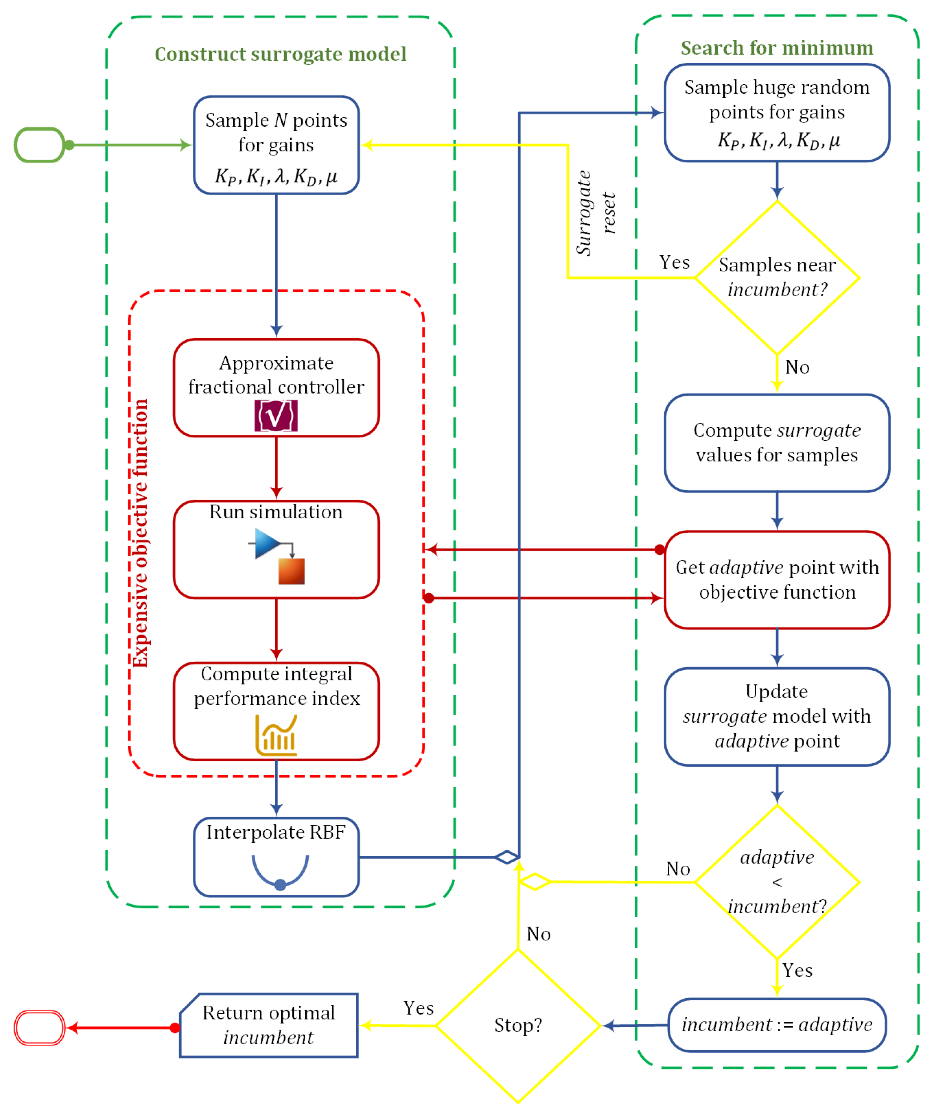
Surrogate optimization is an algorithm that seeks to find the global optimum of an objective function by evaluating an appropriate surrogate model. The surrogate model should have better mathematical characteristics and lower computational requirements than the original objective function. In this work, an RBF function was applied as a surrogate model for the performance index objective function. Figure 9 shows a general description of the surrogate optimization algorithm. As depicted in Figure 9, the algorithm occasionally switched between surrogate modeling and searching for the optimal value. In the following subsections, each of the two modes is explained in more detail.
5.1. Surrogate Modeling
The algorithm initially computes a set of sample points where N is the minimum number for constructing the surrogate model. Each point is a vector containing the fractional PID controller parameters that are subject to bound constraints. These sample points are uniformly randomly sampled around the best obtained objective function since the last surrogate reset, which is called the incumbent point. Then, the performance index values are computed at the initial points exhibiting a computationally intensive objective function, because it runs an approximation of the fractional PID as an integer-order filter with a system model simulation. Consequently, a surrogate model is formulated by interpolating a cubic RBF of the form
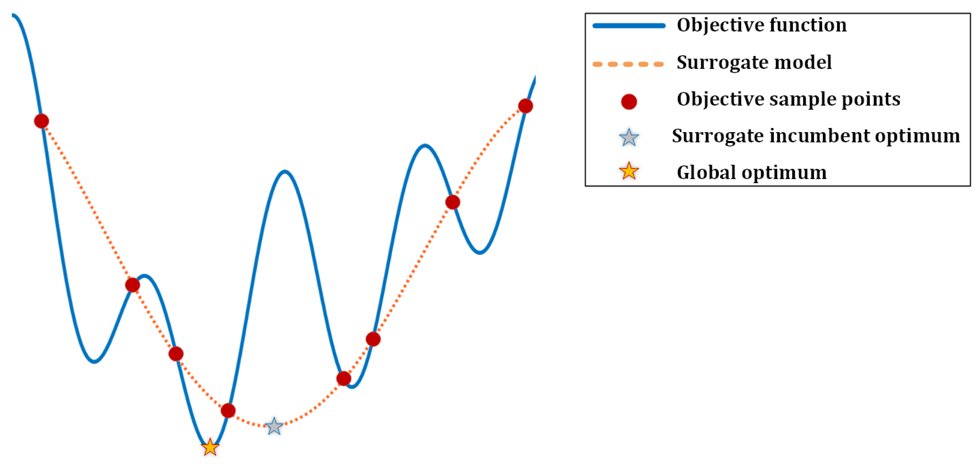
where , , and are the unknown parameters of the surrogate model that can be obtained by solving a linear system of equations [72]. RBF can have different structure choices such as linear, thin plate spline, multi-quadratic, and Gaussian [73]. However, the cubic RBF has been proven to have the optimal integral bumpiness measure [72]. The concept of the surrogate model is illustrated in Figure 10. The blue line represents the complex objective function, and the red circles denote random sample evaluations of the complex objective functions. The red dots are used to fit a surrogate model that is faster to evaluate. The surrogate modeling phase has a low overhead cost in time, as the interpolation is just a linear equation solver and upgrading the interpolation with a new point is computationally insignificant.
5.2. Optimization of the Surrogate Model
The algorithm attempts to optimize a proxy objective function known as the merit function. The merit function is a metric stochastic response surface method that generates a score to select the next potential point for computing the expensive objective function [39]. The merit function is defined as a weighted convex combination of a response surface criterion and a distance criterion, as follows:
where is a weighting factor. The response surface criterion is defined as
Similarly, the distance criterion is defined as
where is the minimum value in the set of distances between x and the computed expensive points.
The optimization mode assumes a trust region with a predefined area around which it searches for the surrogate minimum by randomly sampling a huge number of points. The merit function gives an optimal surrogate value representing a compromise between the surrogate optimality and the exploration of new areas. If all the generated sample points lie within a specific threshold distance from the incumbent, the algorithm resets and switches back to the surrogate modeling mode.
6. Results and Discussion
In this section, the potential of surrogate optimization for tuning fractional controllers was investigated through simulation and real-time experiments. The methodology applied here relied on evaluating the surrogate optimization for decoupled FPIDs for a waypoint navigational controller of a benchmark quadrotor model. Then, surrogate optimization was employed for tuning cross-coupled FPIDs for a real-time twin-rotor copter system. For the controllers in this section, surrogate optimization was carried out on a desktop computer with an Intel Core i5 10th generation GHz CPU and GB RAM. The surrogate optimization was configured with 50 points as the minimum surrogate points and a minimum distance of . The stopping condition was selected as a maximum of 1000 objective function evaluations.
6.1. Quadrotor Optimization Results
The surrogate optimization was applied to minimize the performance index in Equation (12) as an objective function for step signal input commands. To further evaluate the capabilities of the surrogate-tuned FPIDs, comparisons with GA-tuned PID and FOPID were conducted and analyzed. The three sets of controllers GA-PID, GA-FOPID, and surrogate FOPID were run for ten trials to investigate the repeatability and convergence characteristics of the obtained solutions.
Table 2 presents the statistical characteristics of the ten trial runs for the GA and surrogate optimization PID and FOPID controllers. Based on the minimum and mean values or the three axes of the position vectors, the surrogate FOPID achieved a performance index very close to optimal compared to the other two GA-tuned controllers. In addition, it exhibited a stable convergence behavior with a relatively low standard deviation to mean ratio. The surrogate tuning of FOPID required a comparatively efficient computation time. It should be noted that the code profiling of the algorithm runs may produce inaccurate timing estimations as it is hard to guarantee the same run-time conditions and resources within a regular operating system. However, theoretically, under the same assumption, the FOPID surrogate was the fastest to reach the optimal performance index considering the number of simulations and objective function evaluations. The obtained PID and FOPID gains are listed in Table 3.
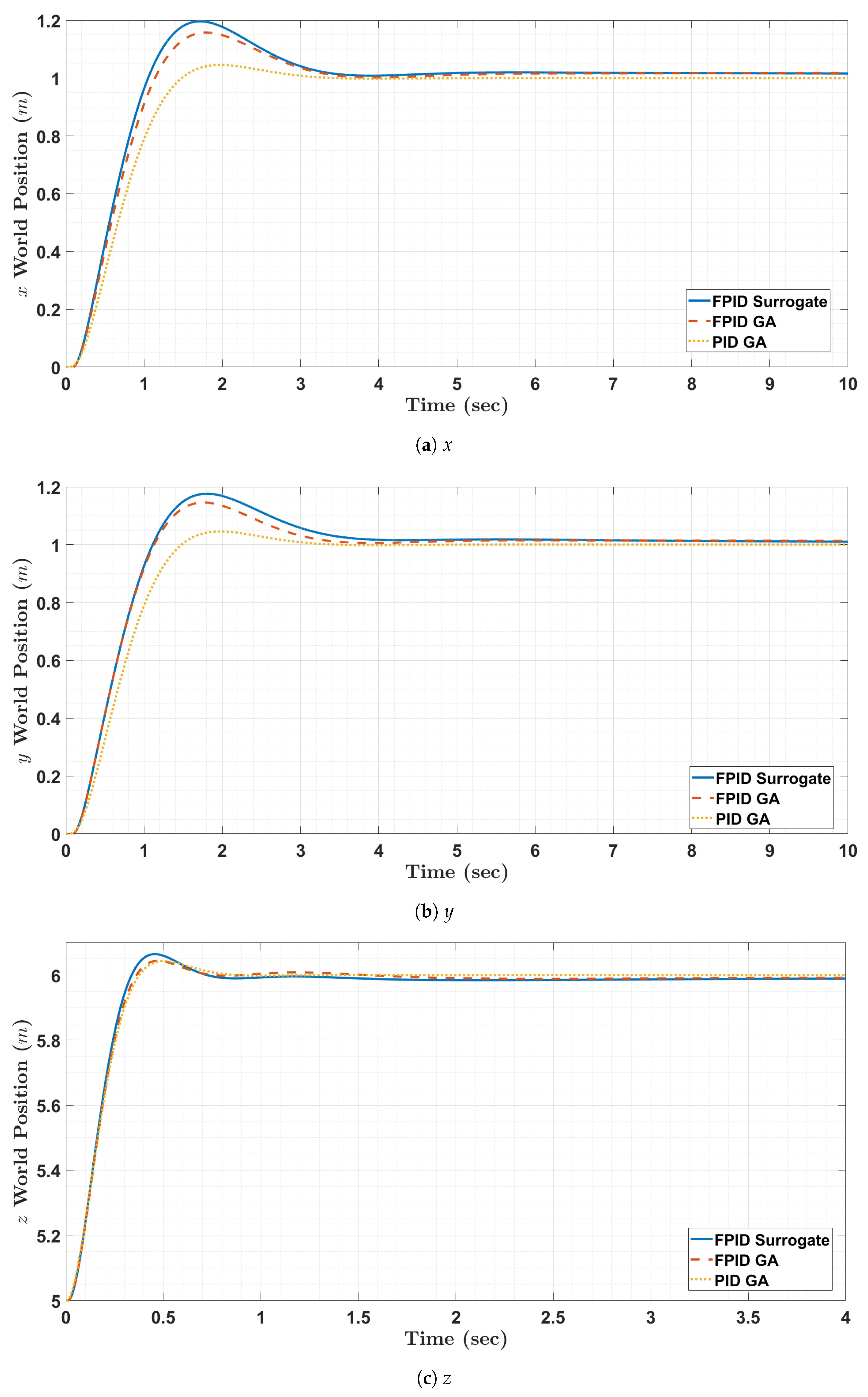
6.2. Simulation of Quadrotor Controllers
The three optimal controllers from each set of trials were simulated and compared with a decoupled step response for each element in the world position vector. The quadrotor position step responses are plotted in Figure 11. The step responses exhibited an insignificant increase in overshoot for FOPID controllers, with mostly typical steady-state characteristics for the three controllers. The step response time-domain characteristics are computed in Table 4. The numeric results of the step responses showed that the surrogate FOPID was slightly smoother, with a faster rise time and a higher overshoot than the PID and FOPID controllers tuned with GA. The PID controller had the best steady-state characteristics, with a steady-state error close to zero. This steady-state behavior was expected, as the PID had a pure integrator that eliminated the steady-state error.
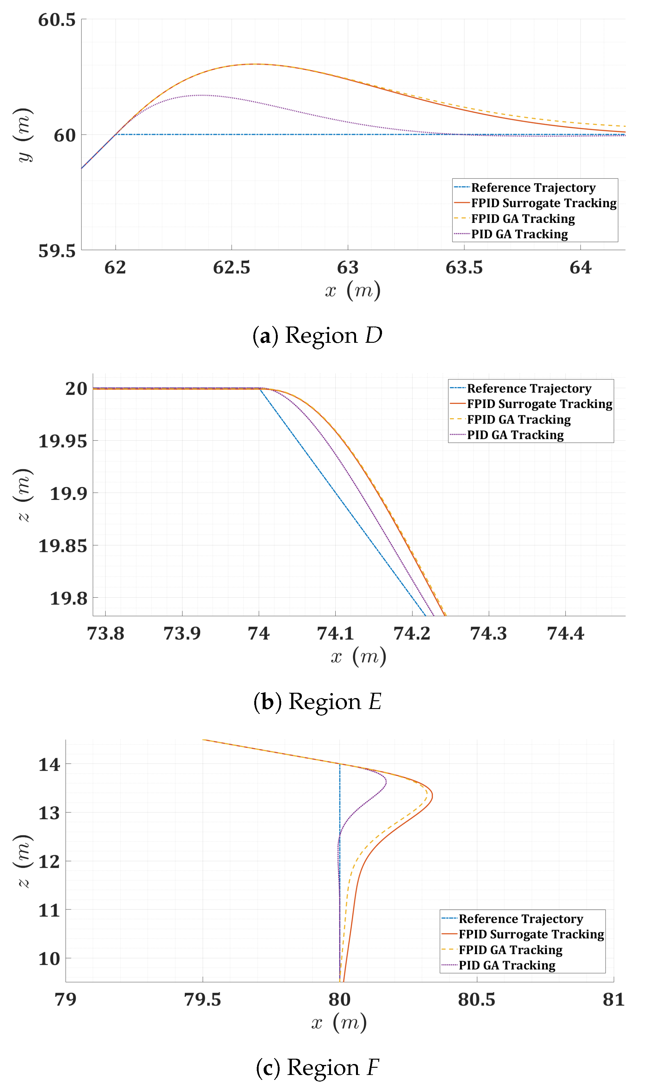
For further validation and investigation of the three controllers, a mission scenario was simulated and analyzed. The mission contained a predefined trajectory that fit a set of planned waypoints. The trajectory was simulated and is plotted in Figure 12. By having a wider focus on the regions of interests A to F in Figure 13 and Figure 14, it is obvious that the FOPID controllers achieved smoother transitions than the PID controller. This behavior can be explained with the histograms of control actions in Figure 15. The PID controller applied a wider range of control actions with more aggressive commands, while the FOPID controller’s actions were tightened, allowing for smoother and more stable transitions. From another point of view, the power spectral densities for the acceleration vector components are plotted in Figure 16. The FOPID controllers exhibited lower amplitudes for the frequency components than the PID controller. This also indicates a more stable behavior in the quadrotor mission for the FOPID control.
6.3. Twin-Rotor Copter Optimization Results
For the twin-rotor copter, surrogate optimization was applied to minimize the performance index in Equation (12) for step signal input commands for the four cross-coupled FOPID controllers shown in Figure 7. First, each straight FOPID controller was tuned in a decoupled configuration. Then, the cross-FOPID controllers or decouplers were tuned to eliminate the cross-coupling effects. The statistical measures of the twin-rotor copter are computed in Table 5, while the optimal FOPID controller gains are presented in Table 6. The obtained optimal gains are visualized in Figure 17. The convergence plots of the surrogate iterations are shown in Figure 18. The convergence plots imply that the surrogate tuning of the controllers reached optimal solutions very quickly, within a few surrogate resets. As shown in the figure, it was not always necessary to consume the maximum allowed number of function evaluations to reach the optimal value.
6.4. Real-Time Validation
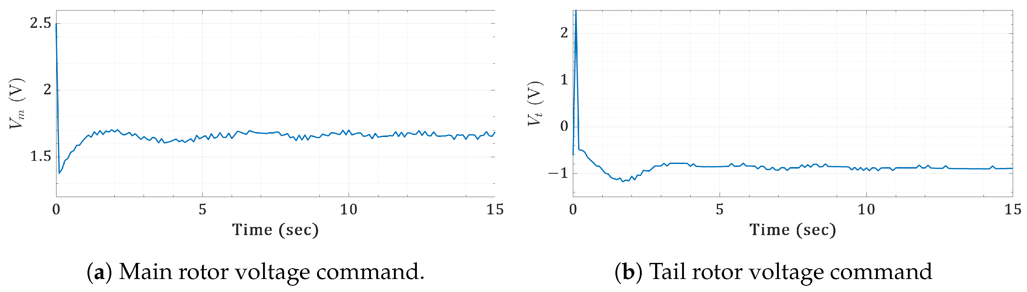
The cross-coupled FOPID controller was approximated and emulated in a discrete equivalent with a sampling time of 0.1 s, to be evaluated through various real-time test cases in a noisy environment. Figure 19 shows the step responses for the orientation angles of the twin-rotor copter, with the corresponding control action shown in Figure 20. Figure 21 and Figure 22 show a real-time sinusoidal response test case with the corresponding rotor voltage control action. Similarly, Figure 23 and Figure 24 depict a sawtooth real-time test case. By investigating the real-time scenarios, the surrogate-tuned cross-coupled FOPID controller exhibited powerful tracking capabilities with efficient control actions.
7. Conclusions and Future Prospects
In pursuit of designing optimal controllers for drone systems, this paper introduced and investigated the application of surrogate-based optimization for FOPID controller tuning for UAV systems. UAV systems have different applications, with variant scales that are subject to tight constraints at the operational level. For example, a battery-powered drone may require certain maneuvers at minimum energy consumption to achieve the mission within one charge cycle. In another scenario, copter systems are required to perform certain scanning and monitoring missions with the most stable performance indices that exhibit a very low vibration profile. Therefore, optimal control design is mandatory to meet the requirements and constraints of UAV systems at the operational level.
Accordingly, the conducted work targeted the fine-tuning of the approximated compensators for FOPID, to achieve more stable and smoother trajectories of UAV systems in conjunction with maintaining energy efficiency. While fractional-order controllers have mathematically intricate structures, the potential of SBAO was investigated for the corresponding computationally intensive optimization problem. FOPID controllers offer more dynamic flexibility than IOPID. This is distinguished by the fractional-order powers that increase the degree of freedom and stretch the frequency response of the resulting integer-order compensators. This flexibility empowers these controllers to handle a diverse range of dynamic scenarios in UAV systems. Meanwhile, this advantage is demonstrated by the inherent challenges in tuning FOPID controllers.
Subsequently, this paper proved that surrogate-based optimization can provide a significantly accelerated tuning adopting a cubic RBF function as an approximation for the objective function. The surrogate-based outcome was noted to be approximately faster than GA, as one of the most widely used global optimization algorithms. This enhancement was achieved while maintaining profoundly close optimal results for both techniques. The SBAO approach identified an optimal FOPID configuration characterized by a substantially high order and adaptability to a wide range of the emulated frequencies. This showed that SBAO has the capability of exploiting the complexity boundaries for UAV sophisticated control systems. The SBOA of FOPID was investigated and assessed using two UAV systems: a simulated quadrotor, and a real-time twin-rotor copter. The simulation of the quadrotor mission demonstrated that the FOPID controllers exhibited smoother and more stable trajectory tracking than the IOPID controllers. The statistical histograms of the controllers’ action showed more tightened activity with FOPID than with IOPID. Meanwhile, the spectral analysis of the acceleration vector components indicated a increased frequency power with the IOPID controller. Furthermore, the twin-rotor copter real-time experiments revealed the applicability of the complex FOPID approximation within the required sample time. The twin-rotor copter followed variant patterns of reference trajectories with acceptable time-domain performance characteristics in a noisy environment. As this work was targeting energy efficiency and smooth tracking measures, the objective optimization function imposed equal weights for tracking error and normalized control actions. However, other objectives could be achieved, such as precise control by imposing a higher weight for tracking error.
Given these concluding points regarding the behavior of FOPID under SBAO, future work may consider two pivotal directions. The first is to investigate different variant configurations of surrogate-based optimization. For example, altering the surrogate model rather than cubic RBF might affect the optimality of the obtained solution. In addition, the sampling function can influence the efficiency of the solution. The other direction is to target more efficient digital FOPID controllers. Instead of the emulation of continuous integer-order approximations applied in this research, future work could focus on implementing more-efficient digital approaches. This would involve developing controllers that incorporate the advantages of FOPID, as well as having optimal digital implementations. From a global point of view, surrogate optimization can serve not only at the low-level tuning of controllers at the operational level but can also provide optimal decisions at the tactical and strategic levels for a more energy-efficient and flexible handling of UAV missions.
Author Contributions
Conceptualization, A.M.M. and M.B.A.; methodology, A.M.M., M.B.A. and K.M.M.; software, A.M.M., M.B.A. and K.M.M.; validation, A.M.M. and M.B.A.; investigation, M.M. (Mohammed Moness) and M.M. (Moataz Mohamed); resources, M.M. (Mohammed Moness) and M.M. (Moataz Mohamed); writing—original draft preparation, K.M.M.; writing—review and editing, A.M.M., M.B.A. and M.M. (Moataz Mohamed); supervision, M.M. (Mohammed Moness) and M.M. (Moataz Mohamed). All authors have read and agreed to the published version of the manuscript.
Funding
The authors would like to acknowledge support from the Natural Sciences and Engineering Research Council of Canada (NSERC) Grant No: RGPIN-2018-05994.
Data Availability Statement
The data are available upon request from the corresponding author.
Conflicts of Interest
The authors declare no conflicts of interest.
References
- Moustafa, A.M.; Abdelghany, M.B.; Younis, A.S.A.; Moness, M.; Al-Durra, A.; Guerrero, J.M. Software-defined control of an emulated hydrogen energy storage for energy internet ecosystems. Int. J. Hydrogen Energy 2024, 50, 893–909. [Google Scholar] [CrossRef]
- IEA. Implementing Clean Energy Transitions Focus on Road Transport in Emerging Economies; Technical Report; International Energy Agency: Paris, France, 2023. [Google Scholar]
- Kellermann, R.; Biehle, T.; Fischer, L. Drones for parcel and passenger transportation: A literature review. Transp. Res. Interdiscip. Perspect. 2020, 4, 100088. [Google Scholar] [CrossRef]
- Shavarani, S.M.; Nejad, M.G.; Rismanchian, F.; Izbirak, G. Application of hierarchical facility location problem for optimization of a drone delivery system: A case study of Amazon prime air in the city of San Francisco. Int. J. Adv. Manuf. Technol. 2018, 95, 3141–3153. [Google Scholar] [CrossRef]
- Abdelghany, M.B.; Moustafa, A.M.; Moness, M. Benchmarking Tracking Autopilots for Quadrotor Aerial Robotic System Using Heuristic Nonlinear Controllers. Drones 2022, 6, 379. [Google Scholar] [CrossRef]
- Moness, M.; Mostafa, A.M. An algorithm for parameter estimation of twin-rotor multi-input multi-output system using trust region optimization methods. Proc. Inst. Mech. Eng. Part I J. Syst. Control Eng. 2013, 227, 435–450. [Google Scholar] [CrossRef]
- Moness, M.; Moustafa, A.M. Tuning a digital multivariable controller for a lab-scale helicopter system via simulated annealing and evolutionary algorithms. Trans. Inst. Meas. Control 2015, 37, 1254–1273. [Google Scholar] [CrossRef]
- ElSayed, M.; Foda, A.; Mohamed, M. The impact of civil airspace policies on the viability of adopting autonomous unmanned aerial vehicles in last-mile applications. Transp. Policy 2024, 145, 37–54. [Google Scholar] [CrossRef]
- Somefun, O.A.; Akingbade, K.; Dahunsi, F. The dilemma of PID tuning. Annu. Rev. Control 2021, 52, 65–74. [Google Scholar] [CrossRef]
- Joseph, S.B.; Dada, E.G.; Abidemi, A.; Oyewola, D.O.; Khammas, B.M. Metaheuristic algorithms for PID controller parameters tuning: Review, approaches and open problems. Heliyon 2022, 8, e09399. [Google Scholar] [CrossRef] [PubMed]
- Bouabdallah, S. Design and Control of Quadrotors with Application to Autonomous Flying. Ph.D. Thesis, Swiss Federal Institute of Technology Lausanne, Lausanne, Switzerland, 2007. [Google Scholar]
- Ozbek, N.S.; Onkol, M.; Efe, M.O. Feedback control strategies for quadrotor-type aerial robots: A survey. Trans. Inst. Meas. Control 2016, 38, 529–554. [Google Scholar] [CrossRef]
- Lopez-Sanchez, I.; Moreno-Valenzuela, J. PID control of quadrotor UAVs: A survey. Annu. Rev. Control 2023, 56, 100900. [Google Scholar] [CrossRef]
- Pounds, P.E.I. Design, Construction and Control of a Large Quadrotor Micro Air Vehicle. Ph.D. Thesis, Australian National University, Canberra, Australia, 2007. [Google Scholar]
- Goel, R.; Shah, S.M.; Gupta, N.K.; Ananthkrishnan, N. Modeling, simulation and flight testing of an autonomous quadrotor. In Proceedings of the ICEAE, Bangalore, India, 18–22 May 2009; pp. 1–7. [Google Scholar]
- Li, J.; Li, Y. Dynamic analysis and PID control for a quadrotor. In Proceedings of the 2011 IEEE International Conference on Mechatronics and Automation, Beijing, China, 7–10 August 2011; pp. 573–578. [Google Scholar]
- Gautam, D.; Ha, C. Control of a Quadrotor Using a Smart Self-Tuning Fuzzy PID Controller. Int. J. Adv. Robot. Syst. 2013, 10, 380. [Google Scholar] [CrossRef]
- Yang, R.; Gao, Y.; Wang, H.; Ni, X. Fuzzy Neural Network PID Control Used in Individual Blade Control. Aerospace 2023, 10, 623. [Google Scholar] [CrossRef]
- Sengupta, S.; Dey, C. Optimal Auto-Tuned PID Controller for Twin Rotor MIMO System. In Advanced Engineering Optimization through Intelligent Techniques; Venkata Rao, R., Taler, J., Eds.; Springer: Singapore, 2023; pp. 591–601. [Google Scholar]
- Marie, M.J.; AL-Suhail, G.A.; Latif, W.A. PSO-based optimal PID controller for twin rotor MIMO system. Int. J. Comput. Technol. 2015, 14, 5719–5730. [Google Scholar] [CrossRef]
- Sivadasan, J.; Shiney, J.R.J. Performance evaluation of a non linear PID controller using chaotic gravitational search algorithm for a twin rotor system. Adv. Control Appl. 2023, 5, e162. [Google Scholar] [CrossRef]
- Su, H.; Ye, Y.; Chen, X.; He, H. Necessary and Sufficient Conditions for Consensus in Fractional-Order Multiagent Systems via Sampled Data Over Directed Graph. IEEE Trans. Syst. Man Cybern. Syst. 2021, 51, 2501–2511. [Google Scholar] [CrossRef]
- Zhang, Y.; Wu, H.; Cao, J. Group Consensus in Finite Time for Fractional Multiagent Systems With Discontinuous Inherent Dynamics Subject to Hölder Growth. IEEE Trans. Cybern. 2022, 52, 4161–4172. [Google Scholar] [CrossRef] [PubMed]
- Machado, J.T.; Kiryakova, V.; Mainardi, F. Recent history of fractional calculus. Commun. Nonlinear Sci. Numer. Simul. 2011, 16, 1140–1153. [Google Scholar] [CrossRef]
- Pham, V.T.; Vaidyanathan, S.; Volos, C.K.; Azar, A.T.; Hoang, T.M.; Van Yem, V. A Three-Dimensional No-Equilibrium Chaotic System: Analysis, Synchronization and Its Fractional Order Form. In Fractional Order Control and Synchronization of Chaotic Systems; Azar, A.T., Vaidyanathan, S., Ouannas, A., Eds.; Springer International Publishing: Cham, Switzerland, 2017; pp. 449–470. [Google Scholar]
- Alsaade, F.W.; Jahanshahi, H.; Yao, Q.; Al-zahrani, M.S.; Alzahrani, A.S. On the Development of a Data-Driven-Based Fractional-Order Controller for Unmanned Aerial Vehicles. Fractal Fract. 2023, 7, 236. [Google Scholar] [CrossRef]
- Hasan, A.F.; Humaidi, A.J.; Al-Obaidi, A.S.M.; Azar, A.T.; Ibraheem, I.K.; Al-Dujaili, A.Q.; Al-Mhdawi, A.K.; Abdulmajeed, F.A. Fractional Order Extended State Observer Enhances the Performance of Controlled Tri-copter UAV Based on Active Disturbance Rejection Control. In Mobile Robot: Motion Control and Path Planning; Azar, A.T., Kasim Ibraheem, I., Jaleel Humaidi, A., Eds.; Springer International Publishing: Cham, Switzerland, 2023; pp. 439–487. [Google Scholar]
- Wang, H.; Li, N.; Luo, Q. Adaptive fractional-order nonsingular fast terminal sliding mode formation control of multiple quadrotor UAVs-based distributed estimator. Asian J. Control 2023, 25, 3671–3686. [Google Scholar] [CrossRef]
- Liu, Z.; Huang, D.; Li, S.; Zhang, W.; Lu, H. Adaptive Robust Control of the UAV-USV Heterogeneous System with Unknown Fractional-Order Dynamics under Multiple Disturbances. In Proceedings of the 2023 42nd Chinese Control Conference (CCC), Tianjin, China, 24–26 July 2023; pp. 5872–5877. [Google Scholar] [CrossRef]
- Yu, Z.; Yang, Z.; Sun, P.; Zhang, Y.; Jiang, B.; Su, C.Y. Refined fault tolerant tracking control of fixed-wing UAVs via fractional calculus and interval type-2 fuzzy neural network under event-triggered communication. Inf. Sci. 2023, 644, 119276. [Google Scholar] [CrossRef]
- Shao, S.; Chen, M. Robust discrete-time fractional-order control for an unmanned aerial vehicle based on disturbance observer. Int. J. Robust Nonlinear Control 2022, 32, 4665–4682. [Google Scholar] [CrossRef]
- Pouzesh, M.; Mobayen, S. Event-triggered fractional-order sliding mode control technique for stabilization of disturbed quadrotor unmanned aerial vehicles. Aerosp. Sci. Technol. 2022, 121, 107337. [Google Scholar] [CrossRef]
- Dong, R. Differential Evolution Versus Particle Swarm Optimization for PIλDμ Controller Design. In Proceedings of the 2009 Fifth International Conference on Natural Computation, Tianjian, China, 14–16 August 2009; Volume 3, pp. 236–240. [Google Scholar]
- Cajo, R.; Thi, T.M.; Copot, C.; Plaza, D.; Keyser, R.D.; Ionescu, C. Multiple UAVs Formation for Emergency Equipment and Medicines Delivery Based on Optimal Fractional Order Controllers. In Proceedings of the 2019 IEEE International Conference on Systems, Man and Cybernetics (SMC), Bari, Italy, 6–9 October 2019; pp. 318–323. [Google Scholar] [CrossRef]
- Stolfi, D.H.; Danoy, G. Evaluating Surrogate Models for Robot Swarm Simulations. In Optimization and Learning; Dorronsoro, B., Chicano, F., Danoy, G., Talbi, E.G., Eds.; Springer: Cham, Switzerland, 2023; pp. 224–235. [Google Scholar]
- Wu, Z.; Zeng, J.; Hu, Z.; Todd, M.D. Optimization of unmanned aerial vehicle inspection strategy for infrastructure based on model-enabled diagnostics and prognostics. Mech. Syst. Signal Process. 2023, 204, 110841. [Google Scholar] [CrossRef]
- Tang, Q.; Li, Y.; Deng, Z.; Chen, D.; Guo, R.; Huang, H. Optimal shape design of an autonomous underwater vehicle based on multi-objective particle swarm optimization. Nat. Comput. 2020, 19, 733–742. [Google Scholar] [CrossRef]
- Yue, H.; Medromi, H.; Ding, H.; Bassir, D. A novel hybrid drone for multi-propose aerial transportation and its conceptual optimization based on surrogate approach. J. Phys. Conf. Ser. 2021, 1972, 012103. [Google Scholar] [CrossRef]
- Regis, R.G.; Shoemaker, C.A. A Stochastic Radial Basis Function Method for the Global Optimization of Expensive Functions. INFORMS J. Comput. 2007, 19, 497–509. [Google Scholar] [CrossRef]
- Palar, P.S.; Liem, R.P.; Zuhal, L.R.; Shimoyama, K. On the use of surrogate models in engineering design optimization and exploration. In Proceedings of the Genetic and Evolutionary Computation Conference Companion, Prague, Czech Republic, 13–17 July 2019; pp. 1592–1602. [Google Scholar] [CrossRef]
- Forrester, A.I.J.; Sóbester, A.; Keane, A.J. Constructing a Surrogate. In Engineering Design via Surrogate Modelling; Wiley Online Books; Wiley: Hoboken, NJ, USA, 2008; pp. 33–76. [Google Scholar] [CrossRef]
- Rosales-Asensio, E.; Rosales, A.E.; Colmenar-Santos, A. Surrogate optimization of coupled energy sources in a desalination microgrid based on solar PV and wind energy. Desalination 2021, 500, 114882. [Google Scholar] [CrossRef]
- Bahlawan, H.; Morini, M.; Pinelli, M.; Spina, P.R.; Venturini, M. Simultaneous optimization of the design and operation of multi-generation energy systems based on life cycle energy and economic assessment. Energy Convers. Manag. 2021, 249, 114883. [Google Scholar] [CrossRef]
- Farhadi, F.; Golestani, S.J.; Teneketzis, D. A Surrogate Optimization-Based Mechanism for Resource Allocation and Routing in Networks With Strategic Agents. IEEE Trans. Autom. Control 2019, 64, 464–479. [Google Scholar] [CrossRef]
- Li, Y.; Xiao, S.; Rotaru, M.; Sykulski, J.K. A Dual Kriging Approach with Improved Points Selection Algorithm for Memory Efficient Surrogate Optimization in Electromagnetics. IEEE Trans. Magn. 2016, 52, 1–4. [Google Scholar] [CrossRef]
- Liu, X.; Qu, X.; Ma, X. Optimizing electric bus charging infrastructure considering power matching and seasonality. Transp. Res. Part D Transp. Environ. 2021, 100, 103057. [Google Scholar] [CrossRef]
- Ziółkowski, J.; Lęgas, A.; Szymczyk, E.; Małachowski, J.; Oszczypała, M.; Szkutnik-Rogoż, J. Optimization of the Delivery Time within the Distribution Network, Taking into Account Fuel Consumption and the Level of Carbon Dioxide Emissions into the Atmosphere. Energies 2022, 15, 5198. [Google Scholar] [CrossRef]
- Idrissi, M.; Salami, M.; Annaz, F. A Review of Quadrotor Unmanned Aerial Vehicles: Applications, Architectural Design and Control Algorithms. J. Intell. Robot. Syst. 2022, 104, 22. [Google Scholar] [CrossRef]
- Shaaban, M.; Merzban, M.H.; Khalaf, A.A.M.; Hamed, H.F. Comparison of Various Control Techniques Applied to a Quadcopter. J. Adv. Eng. Trends 2023, 42, 233–244. [Google Scholar] [CrossRef]
- Sabatier, J. Fractional Order Models Are Doubly Infinite Dimensional Models and thus of Infinite Memory: Consequences on Initialization and Some Solutions. Symmetry 2021, 13, 1099. [Google Scholar] [CrossRef]
- Monje, C.A.; Chen, Y.; Vinagre, B.M.; Xue, D.; Feliu-Batlle, V. Fractional-Order Systems and Controls: Fundamentals and Applications; Springer Science & Business Media: London, UK, 2010. [Google Scholar]
- Matsuda, K.; Fujii, H. H(infinity) optimized wave-absorbing control—Analytical and experimental results. J. Guid. Control Dyn. 1993, 16, 1146–1153. [Google Scholar] [CrossRef]
- Maamri, N.; Trigeassou, J.C. A Plea for the Integration of Fractional Differential Systems: The Initial Value Problem. Fractal Fract. 2022, 6, 550. [Google Scholar] [CrossRef]
- Oustaloup, A.; Levron, F.; Mathieu, B.; Nanot, F.M. Frequency-band complex noninteger differentiator: Characterization and synthesis. IEEE Trans. Circuits Syst. I Fundam. Theory Appl. 2000, 47, 25–39. [Google Scholar] [CrossRef]
- Tepljakov, A. Fractional-Order Modeling and Control of Dynamic Systems; Springer: Cham, Switzerland, 2017. [Google Scholar]
- Gude, J.J.; García Bringas, P. A Novel Control Hardware Architecture for Implementation of Fractional-Order Identification and Control Algorithms Applied to a Temperature Prototype. Mathematics 2022, 11, 143. [Google Scholar] [CrossRef]
- Tepljakov, A.; Petlenkov, E.; Belikov, J. Embedded system implementation of digital fractional filter approximations for control applications. In Proceedings of the 2014 21st International Conference Mixed Design of Integrated Circuits and Systems (MIXDES), Lublin, Poland, 19–21 June 2014; pp. 441–445. [Google Scholar] [CrossRef]
- Matusiak, M.; Bakala, M.; Wojciechowski, R. Optimal Digital Implementation of Fractional-Order Models in a Microcontroller. Entropy 2020, 22, 366. [Google Scholar] [CrossRef] [PubMed]
- Tepljakov, A.; Alagoz, B.B.; Yeroglu, C.; Gonzalez, E.; HosseinNia, S.H.; Petlenkov, E. FOPID Controllers and Their Industrial Applications: A Survey of Recent Results. IFAC-PapersOnLine 2018, 51, 25–30. [Google Scholar] [CrossRef]
- Coopmans, C.; Podhradsky, M.; Hoffer, N.V. An open-source real-time UAS flight control prototyping and testing platform with fractional-order horizontal controller example. In Proceedings of the 2016 International Conference on Unmanned Aircraft Systems (ICUAS), Arlington, VA, USA, 7–10 June 2016; pp. 949–956. [Google Scholar] [CrossRef]
- Oustaloup, A.; Mathieu, B.; Lanusse, P. The CRONE Control of Resonant Plants: Application to a Flexible Transmission. Eur. J. Control 1995, 1, 113–121. [Google Scholar] [CrossRef]
- Podlubny, I. Fractional-order systems and PIλDμ controllers. IEEE Trans. Autom. Control 1999, 44, 208–214. [Google Scholar] [CrossRef]
- Chevalier, A.; Francis, C.; Copot, C.; Ionescu, C.M.; De Keyser, R. Fractional-order PID design: Towards transition from state-of-art to state-of-use. ISA Trans. 2019, 84, 178–186. [Google Scholar] [CrossRef] [PubMed]
- Shah, P.; Agashe, S. Review of fractional PID controller. Mechatronics 2016, 38, 29–41. [Google Scholar] [CrossRef]
- Dastjerdi, A.A.; Saikumar, N.; HosseinNia, S.H. Tuning guidelines for fractional order PID controllers: Rules of thumb. Mechatronics 2018, 56, 26–36. [Google Scholar] [CrossRef]
- Mellinger, D.; Michael, N.; Kumar, V. Trajectory generation and control for precise aggressive maneuvers with quadrotors. Int. J. Robot. Res. 2012, 31, 664–674. [Google Scholar] [CrossRef]
- The MathWorks, Inc. UAV Toolbox; The MathWorks, Inc.: Natick, MA, USA, 2023. [Google Scholar]
- Feedback Instruments Ltd. Twin Rotor MIMO System Control Experiments; Report 33-949S; Feedback Instruments Ltd.: Crowborough, UK, 2006. [Google Scholar]
- Moness, M.; Diaa-Eldeen, T. Experimental nonlinear identification of a lab-scale helicopter system using MLP neural network. In Proceedings of the 2017 13th International Computer Engineering Conference (ICENCO), Cairo, Egypt, 27–28 December 2017; pp. 166–171. [Google Scholar] [CrossRef]
- Moness, M.; Diaa-Eldeen, T. Experimental black-box dynamic modelling of a Flexible Manoeuvring System. In Proceedings of the 2017 12th International Conference on Computer Engineering and Systems (ICCES), Cairo, Egypt, 19–20 December 2017; pp. 259–265. [Google Scholar] [CrossRef]
- Hamamci, S.E. Stabilization using fractional-order PI and PID controllers. Nonlinear Dyn. 2008, 51, 329–343. [Google Scholar] [CrossRef]
- Powell, M.J.D. The theory of radial basis function approximation in 1990. Adv. Numer. Anal. 1992, 2, 105–210. [Google Scholar]
- Gutmann, H.M. A Radial Basis Function Method for Global Optimization. J. Glob. Optim. 2001, 19, 201–227. [Google Scholar] [CrossRef]
Figure 1.
Challenge complexity of intersecting decision levels and constraints of UAV operation.

Figure 2.
Design optimization criterion with its reflection in a set of operational requirements.

Figure 3.
Frequency responses for a sample of FOPID with unity gains.

Figure 4.
The quadrotor model frames.

Figure 5.
The quadrotor waypoint navigation FOPID control structure.

Figure 6.
The twin-rotor copter physical setup.

Figure 7.
The twin-rotor copter cross-coupled FOPID control.

Figure 8.
Stability boundaries in the – plane for arbitrarily selected values of .

Figure 9.
Flowchart of the surrogate optimization algorithm.

Figure 10.
Conceptual plot of the surrogate optimization algorithm.

Figure 11.
Position step responses for the quadrotor.

Figure 12.
Simulation of the mission scenario for the quadrotor.

Figure 13.
Zoomed 2D planar view for the quadrotor mission trajectory at transitional regions (A, B, and C).
Figure 13.
Zoomed 2D planar view for the quadrotor mission trajectory at transitional regions (A, B, and C).

Figure 14.
Zoomed 2D planar view for the quadrotor mission trajectory at transitional regions (D, E, and F).
Figure 14.
Zoomed 2D planar view for the quadrotor mission trajectory at transitional regions (D, E, and F).

Figure 15.
Histogram of control actions for the quadrotor.


Figure 16.
Acceleration power spectral density for the quadrotor mission.


Figure 17.
Visualization of the optimal FOPID controllers for the twin-rotor copter.

Figure 18.
Convergence of surrogate optimization for the FOPID controllers of the twin-rotor copter.
Figure 18.
Convergence of surrogate optimization for the FOPID controllers of the twin-rotor copter.


Figure 19.
Real-time orientation step responses for the twin-rotor copter.

Figure 20.
Real-timecontrol actions of the step commands for the twin-rotor copter.

Figure 21.
Real-time orientation sinusoidal responses for the twin-rotor copter.

Figure 22.
Real-time control actions of the sinusoidal commands for the twin-rotor copter.

Figure 23.
Real-time orientation sawtooth responses for the twin-rotor copter.

Figure 24.
Real-time control actions of the sawtooth commands for the twin-rotor copter.


Table 1.
The quadrotor model parameters [67].
Table 1.
The quadrotor model parameters [67].
| Parameter | Value |
|---|---|
| (s−2) | 3402.97 |
| (s−1) | 116.67 |
| (s−2) | 3402.97 |
| (s−1) | 116.67 |
| (s−1) | 1950 |
| (s−1) | 3900 |
| m (kg) | 0.1 |
Table 2.
Statistical measures of the quadrotor controller optimization.
| Axis | Controller | Objective Function | Computation Time (min) | ||||||
|---|---|---|---|---|---|---|---|---|---|
| Min. Value | Mean | Median | Standard Deviation | Average Simulations Count | Mean | Median | Standard Deviation | ||
| x | PID-GA | 664.2483 | 665.0124 | 664.3411 | 1.1576 | 2450 | 14.0791 | 14.0254 | 1.4368 |
| FOPID-GA | 672.5661 | 679.6325 | 678.4195 | 6.8963 | 2517 | 26.3810 | 26.3464 | 3.1829 | |
| FOPID-Surrogate | 672.0003 | 683.4908 | 680.4865 | 8.3657 | 1000 | 11.1183 | 10.9377 | 0.5672 | |
| y | PID-GA | 664.2483 | 665.0124 | 664.3411 | 1.1576 | 2450 | 7.0880 | 7.0214 | 0.9581 |
| FOPID-GA | 673.3710 | 680.4129 | 676.7823 | 8.0841 | 2497 | 21.9964 | 20.4116 | 4.2519 | |
| FOPID-Surrogate | 677.0695 | 682.9058 | 681.5786 | 5.5742 | 1000 | 10.4262 | 10.0240 | 0.7907 | |
| z | PID-GA | 274.7040 | 274.7089 | 274.7041 | 0.0125 | 2450 | 9.5922 | 9.3179 | 1.4732 |
| FOPID-GA | 286.9981 | 289.5838 | 288.8558 | 3.1095 | 2450 | 25.4097 | 23.9121 | 5.1696 | |
| FOPID-Surrogate | 287.9273 | 289.4379 | 289.1571 | 1.2448 | 1000 | 19.3086 | 19.3221 | 1.0178 | |
Table 3.
PID and FOPID gains for the quadrotor controllers.
| Axis | Controller | |||||
|---|---|---|---|---|---|---|
| x | PID-GA | 0.4598 | 0 | 1 | 0.3061 | 1 |
| FOPID-GA | 0.0696 | 0.0089 | 0.9053 | 0.2196 | 0.7202 | |
| FOPID-Surrogate | 0 | 0.0205 | 0.6440 | 0.2480 | 0.6292 | |
| y | PID-GA | 0.4598 | 0 | 1 | 0.3061 | 1 |
| FOPID-GA | 0.0574 | 0.0244 | 0.5658 | 0.2389 | 0.7197 | |
| FOPID-Surrogate | 0.0376 | 0.0544 | 0.4275 | 0.2375 | 0.7272 | |
| z | PID-GA | 8.6983 | 5.8476 | 1 | 1.3159 | 1 |
| FOPID-GA | 0.7844 | 7.6204 | 0.8063 | 2.1821 | 0.6411 | |
| FOPID-Surrogate | 0.6607 | 7.9986 | 0.7507 | 2.2529 | 0.6387 |
Table 4.
Time-domain characteristics for quadrotor step responses.
| Axis | Controller | Rise Time (s) | Overshoot | Settling Time (s) | Settling Error |
|---|---|---|---|---|---|
| x | PID-GA | 0.9164 | 4.5587 | 2.6726 | 1.5332 |
| FOPID-GA | 0.7591 | 13.7547 | 2.9700 | 0.0177 | |
| FOPID-Surrogate | 0.6958 | 17.7479 | 3.0561 | 0.0161 | |
| y | PID-GA | 0.9164 | 4.5587 | 2.6726 | 1.5332 |
| FOPID-GA | 0.7444 | 13.0912 | 2.9666 | 0.0131 | |
| FOPID-Surrogate | 0.7329 | 16.4277 | 3.4230 | 0.0101 | |
| z | PID-GA | 0.2402 | 4.3196 | 0.6700 | 3.1186 |
| FOPID-GA | 0.2283 | 4.3987 | 0.6157 | 0.0042 | |
| FOPID-Surrogate | 0.2163 | 6.4502 | 0.6352 | 0.0059 |
Table 5.
Statistical measures of the twin-rotor copter controller optimization.
| Controller | Objective Function | Computation Time (min) | |||
|---|---|---|---|---|---|
| Minimum Value | Mean | Standard Deviation | Mean | Standard Deviation | |
| 184.8821 | 207.2058 | 26.6892 | 9.8651 | 0.2540 | |
| 4.9927 | 5.4286 | 0.3315 | 14.2360 | 0.6657 | |
| 0.6314 | 0.7114 | 0.0508 | 15.1317 | 0.3795 | |
| 21.2900 | 23.3846 | 1.5300 | 10.2655 | 1.1018 | |
Table 6.
FOPID gains for the twin-rotor copter controller.
| Controller | |||||
|---|---|---|---|---|---|
Disclaimer/Publisher’s Note: The statements, opinions and data contained in all publications are solely those of the individual author(s) and contributor(s) and not of MDPI and/or the editor(s). MDPI and/or the editor(s) disclaim responsibility for any injury to people or property resulting from any ideas, methods, instructions or products referred to in the content. |
© 2024 by the authors. Licensee MDPI, Basel, Switzerland. This article is an open access article distributed under the terms and conditions of the Creative Commons Attribution (CC BY) license (https://creativecommons.org/licenses/by/4.0/).
Share and Cite
MDPI and ACS Style
Moness, M.; Abdelghany, M.B.; Mohammed, K.M.; Mohamed, M.; Moustafa, A.M. Surrogate Optimal Fractional Control for Constrained Operational Service of UAV Systems. Drones 2024, 8, 141. https://doi.org/10.3390/drones8040141
AMA Style
Moness M, Abdelghany MB, Mohammed KM, Mohamed M, Moustafa AM. Surrogate Optimal Fractional Control for Constrained Operational Service of UAV Systems. Drones. 2024; 8(4):141. https://doi.org/10.3390/drones8040141
Chicago/Turabian StyleMoness, Mohammed, Muhammad Bakr Abdelghany, Khloud Mostafa Mohammed, Moataz Mohamed, and Ahmed M. Moustafa. 2024. "Surrogate Optimal Fractional Control for Constrained Operational Service of UAV Systems" Drones 8, no. 4: 141. https://doi.org/10.3390/drones8040141